P.
Reading edition
PACKFONG, is the Chinese name of the alloy called white copper, or German silver.
PACO, or PACOS, is the Peruvian name of an earthy-looking ore, which consists of brown oxide of iron, with imperceptible particles of native silver disseminated through it.
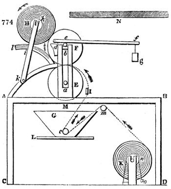
PADDING MACHINE (Machine à plaquer, Fr.; Klatsch, or Grundirmaschine, Germ.); in calico-printing, is the apparatus for imbuing a piece of cotton cloth uniformly with any mordant. In fig. 774. A B C D represents in section a cast-iron frame, supporting two opposite standards above M, in whose vertical slot the gudgeons a b, of two copper or bronze cylinders E F, run; the gudgeons of E turn upon fixed brasses or plummer blocks; but the superior cylinder F rests upon the surface of the under one, and may be pressed down upon it with greater or less force by means of the weighted lever d e f g, whose centre of motion is at d, and which bears down upon the axle of F. K is the roller upon which the pieces of cotton cloth intended to be padded are wound; several of them, being stitched endwise together. They receive tension from the action of a weighted belt o, n, which passes round a pulley n upon the end of the roller K. The trough G, which contains the colouring matter or mordant, rests beneath the cylinder upon the table L, or other convenient support. About two inches above the bottom of the trough, there is a copper dip-roller C, under which the cloth passes, after going round the guide roller m. Upon escaping from the trough, it is drawn over the half-round stretcher-bar at I, grooved obliquely right and left, as shown at N, whereby it acquires a diverging extension from the middle, and enters with a smooth surface between the two cylinders E F. These are lapped round 6 or 7 times with cotton cloth, to soften and equalize their pressure. The piece of goods glides obliquely upwards, in contact with one third of the cylinder F, and is finally wound about the uppermost roller H. The gudgeon of H revolves in the end of the radius h, k, which is jointed at k, and movable by a mortise at i along the quadrantal arc towards l, as the roller K becomes enlarged by the convolutions of the web. The under cylinder E receives motion by a pulley or rigger upon its opposite end, from a band connected with the driving-shaft of the printshop. To ensure perfect equability in the application of the mordant, the goods are in some works passed twice through the trough; the pressure being increased the second time by sliding the weight g to the end of the lever d f.
A view of a padding machine in connexion with the driving mechanism is given under Hot Flue; see also Starching Machine.
PAINT. See Rouge.
PAINTS, GRINDING OF. There are many pigments, such as common orpiment, or king’s yellow, and verdigris, which are strong poisons; others which are very deleterious, and occasion dreadful maladies, such as white lead, red lead, chrome yellow, and vermillion; none of which can be safely ground by hand with the slab and muller, but should always be triturated in a mill. The emanations of white lead cause, first, that dangerous disease the colica pictonum, afterwards paralysis, or premature decrepitude and lingering death.
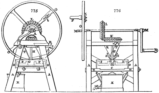
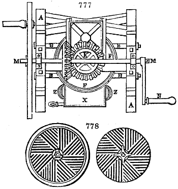
Figs. 775, 776, 777, 778. exhibit the construction of a good colour-mill in three views; fig. 775. being an elevation shown upon the side of the handle, or where the power is applied to the shaft; fig. 776. a second elevation, taken upon the side of the line c, d, of the plan or bird’s-eye view, fig. 777.
The frame-work A A of the mill is made of wood or cast iron, strongly mortised or bolted together; and strengthened by the two cross iron bars B, B. Fig. 778. is a plan of the millstones. The lying or nether millstone C, fig. 776, is of cast iron, and is channelled on its upper face like corn millstones. It is fixed upon the two iron bars B, B; but may be preferably supported upon the 3 points of adjustable screws, passing up through bearing-bars. The millstone C is surrounded by a large iron hoop D, for preventing the pasty-consistenced colour from running over the edge. It can escape only by the sluice hole E, fig. 776., formed in the hoop; and is then received in the tub X placed beneath.
The upper or moving millstone F, is also made of cast iron. The dotted lines indicate its shape. In the centre it has an aperture with ledges G, G; there is also a ledge upon its outer circumference, sufficiently high to confine the colour which may occasionally accumulate upon its surface. An upright iron shaft H passes into the turning stone, and gives motion to it. A horizontal iron bevel wheel K, figs. 776, 777., furnished with 27 wooden teeth, is fixed upon the upper end of the upright shaft H. A similar bevel wheel L, having the same number of teeth, is placed vertically upon the horizontal iron axis M, M, and works into the wheel K. This horizontal axis M, M bears, at one of its ends, a handle or winch N, by which the workman may turn the millstone F; and on the other end of the same axis, the fly-wheel O is made fast, which serves to regulate the movements of the machine. Upon one of the spokes of the fly-wheel there is fixed, in like manner, a handle P, which may serve upon occasion for turning the mill. This handle may be attached at any convenient distance from the centre, by means of the slot and screw-nut J.
The colour to be ground is put into the hopper R, below which the bucket S is suspended, for supplying the colour uniformly through the orifice in the millstone G. A cord or chain T, by means of which the bucket S is suspended at a proper height for pouring out the requisite quantity of colour between the stones, pulls the bucket obliquely, and makes its beak rest against the square upright shaft H. By this means the bucket is continually agitated in such a way as to discharge more or less colour, according to its degree of inclination. The copper cistern X, receives the colour successively as it is ground; and, when full, it may be carried away by the two handles Z, Z; it may be emptied by the stopcock Y, without removing the tub.
PAINTS, VITRIFIABLE. See Porcelain, Pottery, and Stained Glass.
PALLADIUM; a rare metal, possessed of valuable properties; was discovered in 1803, by Dr. Wollaston, in native platinum. It constitutes about 1 per cent. of the Columbian ore, and from 1⁄4 to 1 per cent. of the Uralian ore of this metal; occurring nearly pure in loose grains, of a steel-gray colour, passing into silver white, and of a specific gravity of from 11·8 to 12·14; also as an alloy with gold in Brazil, and combined with selenium in the Harz near Tilkerode. Into the nitro-muriatic solution of native platinum, if a solution of cyanide of mercury be poured, the pale yellow cyanide of palladium will be thrown down, which being ignited affords the metal. This is the ingenious process of Dr. Wollaston. The palladium present in the Brazilian gold ore may be readily separated as follows: melt the ore along with 2 or 3 parts of silver, granulate the alloy, and digest it with heat in nitric acid of specific gravity 1·3. The solution containing the silver and palladium, for the gold does not dissolve, being treated with common salt or muriatic acid, will part with all its silver in the form of a chloride. The supernatant liquor being concentrated and neutralized with ammonia, will yield a rose-coloured salt in long silky crystals, the ammonia-muriate of palladium, which being washed in ice-cold water, and ignited, will afford 40 per cent. of metal.
The metal obtained by this process is purer than that by the former; and if it be fused in a crucible along with borax, by the heat of a powerful air-furnace or forge, a button of malleable and ductile palladium will be produced. When a slip of it is heated to redness, it takes a bronze-blue shade of greater or less intensity, as the slip is cooled more or less slowly; but if it be suddenly chilled, as by plunging it into water, it resumes instantly its white lustre. This curious phenomenon depending upon oxidizement and de-oxidizement, in different circumstances, serves at once to distinguish palladium from platinum.
Pure palladium resembles platinum, but has more of a silver hue; when planished by the hammer into a cup, such as that of M. Bréant, in the museum of the Mint at Paris, it is a splendid steel-white metal, not liable, like silver, to tarnish in the air. Another cup made by M. Bréant, weighing 2 lbs. (1 kilogramme), was purchased by Charles X., and is now in the garde-meuble of the French crown. The specific gravity of this metal, when laminated, is stated by Dr. Wollaston at 11·8, and by Vauquelin at 12·1. It melts at from 150° to 160° Wedgewood; and does not oxidize at a white heat. When a drop of tincture of iodine, is let fall upon the surface of this metal, and dissipated over a lamp flame, a black spot remains, which does not happen with platinum. A slip of palladium has been used with advantage to inlay the limbs of astronomical instruments, where the fine graduated lines are cut, because it is bright, and not liable to alteration, like silver.
There are a protoxide and peroxide of palladium. The proto-chloride consists of 60 of metal and 40 of chlorine; the cyanide, of 67 of metal, and 33 of cyanogen.
PALM OIL (Huile de palme, Fr.; Palmöl, Germ.); is obtained, in Guinea and Guyana, by expressing, as also by boiling, the fruit of the avoira elais. It has an orange colour, a smell of violets, a bland taste, is lighter than water, melts at 84° Fahr., becomes rancid and pale by exposure to air, dissolves in boiling alcohol, and consists of 69 parts of oleine, and 31 of stearine, in 100. It is employed chiefly for making yellow soap. It may be bleached by the action of either chlorine or oxygen gas, as also by that of light and heat.
Palm oil, quantity of,
Imported. Retained for consumption. Exported.
Year. Cwts. Cwts. Cwts.
1835. 260,151 242,733 30,915
1836. 277,017 234,357 34,379
1837. 223,329 214,000
Duty, 1s. 3d. per cwt.
PAPER CUTTING. Mr. T. B. Crompton, of Farnworth, Lancashire, who obtained a patent in May, 1821, for proposing to conduct the newly formed web of paper in the Fourdrinier machine over heated cylinders, for the purpose of drying it expeditiously, in imitation of the mode so long practised in drying calicoes, obtained, along with Enoch Miller, another, in May, 1828, for cutting the endless web of paper lengthwise, by revolving circular blades, fixed upon a roller, parallel to a cylinder, round which the paper is lapped, and progressively unwound.
A patent had been obtained two months before, for certain improvements in cutting paper, by Mr. Edward Cowper, consisting of a machine, with a reel on which the web of paper of very considerable length has been previously wound, in the act of being made in a Fourdrinier’s machine; this web of paper being of sufficient width to produce two, three, or more sheets, when cut.
The several operative parts of the machine are mounted upon standards, or frame-work, of any convenient form or dimensions, and consist: of travelling endless tapes to conduct the paper over and under a series of guide rollers; of circular rotatory cutters for the purpose of separating the web of paper into strips equal to the widths of the intended sheets; and of a saw-edged knife, which is made to slide horizontally for the purpose of separating the strips into such portions or lengths as shall bring them to the dimensions of a sheet of paper.
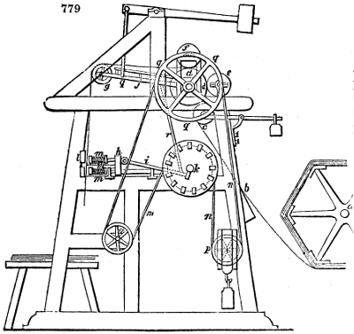
The end of the web of paper from the reel a, fig. 779. is first conducted up an inclined plane b by hand; it is then taken hold of by endless tapes extended upon rollers, as in Mr. Cowper’s Printing Machine, which see. These endless tapes carry the web of paper to the roller c, which is pressed against the roller d by weighted levers, acting upon the plummer blocks that its axle is mounted in. The second roller d may be either of wood or metal, having several grooves formed round its periphery for the purpose of receiving the edges of the circular cutters e, (see Card-cutting) mounted upon an axle turning upon bearings in the standards or frame.
In order to allow the web of paper to proceed smoothly between the two rollers c, d, a narrow rib of leather is placed round the edges of one or both of these rollers, for the purpose of leaving a free space between them, through which the paper may pass without wrinkling.
From the first roller c, the endless tapes conduct the paper over the second d, and then under a pressing roller f, in which progress the edges of the circular knives e, revolving in the grooves of the second roller d, cut the web of paper longitudinally into strips of such widths as may be required, according to the number of the circular cutters and distances between them.
The strips of paper proceed onward from between the knife roller d and pressing roller f, conducted by tapes, until they reach a fourth roller g, when they are allowed to descend, and to pass through the apparatus designed to cut them transversely; that is, into sheet lengths.
The apparatus for cutting the strips into sheets is a sliding knife, placed horizontally upon a frame at h, which frame, with the knife e, is moved to and fro by a jointed rod i, connected to a crank on the axle of the pulley k. A flat board or plate l is fixed to the standard frame in an upright position, across the entire width of the machine; and this board or plate has a groove or opening cut along it opposite to the edge of the knife. The paper descending from the fourth roller g passes against the face of this board, and as the carriage with the knife advances, two small blocks, mounted upon rods with springs m m, come against the paper, and hold it tight to the board or plate l, while the edge of the knife is protruded forward into the groove of that board or plate, and its sharp saw-shaped teeth passing through the paper, cut one row of sheets from the descending strips; which, on the withdrawing of the blocks, falls down, and is collected on the heap below.
The power for actuating this machine is applied to the reverse end of the axle, on which the pulley k is fixed, and a band n, n, n, n, passing from this pulley over tension wheels o, drives the wheel q fixed to the axle of the knife roller d; hence this roller receives the rotatory motion which causes it to conduct forward the web of paper, but the other rollers c and f, are impelled solely by the friction of contact.
The rotation of the crank on the axle of k, through the intervention of the crank-rod i, moves the carriage h, with the knife, to and fro at certain periods, and when the spring blocks m come against the grooved plate l, they slide their guide rods into them, while the knife advances to sever the sheets of paper. But as sheets of different dimensions are occasionally required, the lengths of the slips delivered between each return of the knife are to be regulated by enlarging or diminishing the diameter of the pulley k, which will of course retard or facilitate the rotation of the three conducting rollers, c, d, f, and cause a greater or less length of the paper to descend between each movement of the knife carriage.
The groove of this pulley k, which is susceptible of enlargement, is constructed of wedge-formed blocks passed through its sides, and meeting each other in opposite directions, so that on drawing out the wedges a short distance, the diameter of the pulley becomes diminished; or by pushing the wedges further in, the diameter is increased; and a tension wheel p being suspended in a weighted frame, keeps the band always tight.
As it is necessary that the paper should not continue descending while it is held by the blocks m, m to be cut, and yet that it should be led on progressively over the knife roller d, the fourth roller g, which hangs in a lever j, is made to rise at that time, so as to take up the length of paper delivered, and to descend again when the paper is withdrawn. This is effected by a rod r, connected to the crank on the shaft of the aforesaid roller k, and also to the under part of the lever j, which lever hanging loosely upon the axle of the knife roller d, as its fulcrum, vibrates with the under roller g, so as to effect the object in the way described.
The patentee states that several individual parts of this machine are not new, and that some of them are to be found included in the specifications of other persons, such as the circular cutters e, which are employed by Mr. Dickinson (Card-cutting), and the horizontal cutter h, by Mr. Hansard; he therefore claims only the general arrangement of the parts in the form of a machine for the purpose of cutting paper, as the subject of his invention.
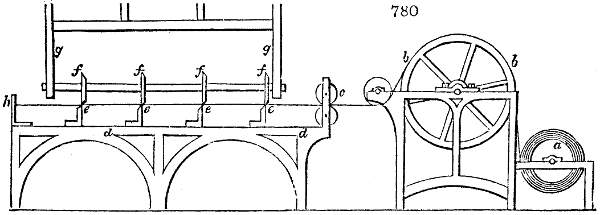
The machine for cutting paper contrived by John Dickinson, Esq. of Nash Mill, was patented in January, 1829. The paper is wound upon a cylindrical roller a, fig. 780., mounted upon an axle, supported in an iron frame or standard. From this roller the paper in its breadth is extended over a conducting drum b, also mounted upon an axle turning in the frame or standard, and after passing under a small guide roller, it proceeds through a pair of drawing or feeding rollers c, which carry it into the cutting machine.
Upon a table d, d, firmly fixed to the floor of the building, there is a series of chisel-edged knives e, e, e, placed at such distances apart as the dimensions of the cut sheets of paper are intended to be. These knives are made fast to the table, and against them a series of circular cutters f, f, f, mounted in a swinging frame g, g, are intended to act. The length of paper being brought along the table over the edges of the knives, up to a stop h, the cutters are then swung forwards, and by passing over the paper against the stationary knives, the length of paper becomes cut into three separate sheets.
The frame g, g, which carries the circular cutters f, f, f, hangs upon a very elevated axle, in order that its pendulous swing may move the cutters as nearly in a horizontal line as possible; and it is made to vibrate to and fro by an eccentric, or crank, fixed upon a horizontal rotatory shaft extending over the drum b, considerably above it, which may be driven by any convenient machinery.
The workmen draw the paper from between the rollers c, and bring it up to the stop h, in the intervals between the passing to and fro of the swing-cutters.
The following very ingenious apparatus for cutting the paper web transversely into any desired lengths, was made the subject of a patent by Mr. E. N. Fourdrinier, in June, 1831, and has since been performing its duty well in many establishments.
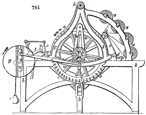
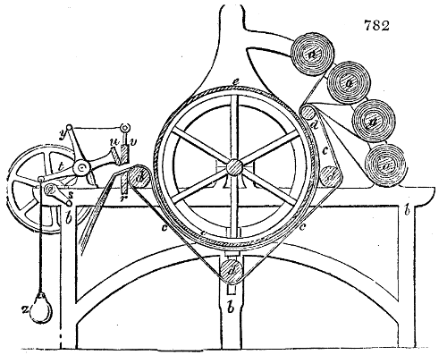
Fig. 781. is an elevation, taken upon one side of the machine; and fig. 782. is a longitudinal section. a, a, a, a, are four reels, each covered with one continuous sheet of paper; which reels are supported upon bearings in the frame-work b, b, b. c, c, c, is an endless web of felt-cloth passed over the rollers d, d, d, d, which is kept in close contact with the under side of the drum e, e, seen best in fig. 782.
The several parallel layers of paper to be cut, being passed between the drum e, and the endless felt c, will be drawn off their respective reels, and fed into the machine, whenever the driving-band is slid from the loose to the fast pulley upon the end of the main shaft f. But since the progressive advance of the paper-webs must be arrested during the time of making the cross cut through it, the following apparatus becomes necessary. A disc g, which carries the pin or stud of a crank i, is made fast to the end of the driving shaft f. This pin is set in an adjustable sliding piece, which may be confined by a screw within the bevelled graduated groove, upon the face of the disc g, at variable distances from the axis, whereby the eccentricity of the stud i, and of course the throw of the crank, may be considerably varied. The crank stud i is connected by its rod j, to the swinging curvilinear rack k, which takes into the toothed wheel l, that turns freely upon the axle of the feed drum e, e. From that wheel the arms m, m, rise, and bear one or more palls n, which work in the teeth of the great ratchet wheel o, o, mounted upon the shaft of the drum e.
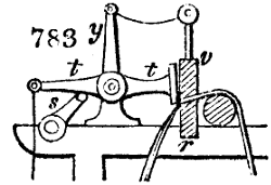
The crank-plate g being driven round in the direction of its arrow, will communicate a see-saw movement to the toothed arc k, next to the toothed wheel l in gearing with it, and an oscillatory motion to the arms m, m, as also to their surmounting pall n. In its swing to the left hand, the catch of the pall will slide over the slope of the teeth of the ratchet wheel o; but in its return to the right hand, it will lay hold of these teeth, and pull them, with their attached drum, round a part of a revolution. The layers of paper in close contact with the under half of the drum will be thus drawn forward at intervals, from the reels, by the friction between its surface and the endless felt, and in lengths corresponding to the arc of vibration of the pall. The knife for cutting these lengths transversely is brought into action at the time when the swing arc is making its inactive stroke, viz., when it is sliding to the left over the slopes of the ratchet teeth o. The extent of this vibration varies according to the distance of the crank stud i, from the centre f, of the plate g, because that distance regulates the extent of the oscillations of the curvilinear rack, and that of the rotation of the drum e, by which the paper is fed forwards to the knife apparatus. The proper length of its several layers being by the above described mechanism carried forward over the bed r of the cutting knife or shears r, v, whose under blade r is fixed, the wiper s, in its revolution with the shaft f, lifts the tail of the lever t, consequently depresses the transverse movable blade v (as shown in fig. 783.), and slides the slanting blades across each other obliquely, like a pair of scissors, so as to cause a clean cut across the plies of paper. But just before the shears begin to operate, the transverse board u descends to press the paper with its edge, and hold it fast upon the bed r. During the action of the upper blade v, against the under r, the fall board u, is suspended by a cord passing across pullies from the arm y of the bell-crank lever t, t. Whenever the lifter cam s, has passed away from the tail of the bell-crank t, the weight z, hung upon it, will cause the blade v, and the pinching board u, to be moved up out of the way of the next length of paper, which is regularly brought forward by the rotation of the drum e, as above described. The upper blade of the shears is not set parallel to the shaft of the drum, but obliquely to it, and is, moreover, somewhat curved, so as to close its edge progressively upon that of the fixed blade. The blade v may also be set between two guide pieces, and have the necessary motion given to it by levers.
PAPER-HANGINGS, called more properly by the French, papiers peints. The art of making paper-hangings, papier de tenture, has been copied from the Chinese, among whom it has been practised from time immemorial. The English first imported and began to imitate the Chinese paper-hangings; but being exposed till very lately to a high excise duty upon the manufacture, they have not carried it to that extent and pitch of refinement which the French genius has been enabled to do, unchecked by taxation. The first method of making this paper was stencilling; by laying upon it, in an extended state, a piece of pasteboard having spaces cut out of various figured devices, and applying different water colours with the brush. Another piece of pasteboard with other patterns cut out was next applied, when the former figures were dry, and new designs were thus imparted. By a series of such operations, a tolerable pattern was executed, but with no little labour and expense. The processes of the calico printer were next resorted to, in which engraved blocks of the pear or sycamore were employed to impress the coloured designs.
Paper-hangings may be distinguished into two classes; 1. those which are really painted, and which are designed in France under the title of papiers peints, with brilliant flowers and figures; and 2. those in which the designs are formed by foreign matters applied to the paper, under the name of papier tontisse, or flock paper.
The operations common to paper-hangings, of both kinds, may be stated as follows:—
1. The paper should be well sized.
2. The edges should be evenly cut by an apparatus like the bookbinder’s press.
3. The ends of each of the 24 sheets which form a piece, should be nicely pasted together; or a Fourdrinier web of paper should be taken.
4. Laying the grounds, is done with earthy colours or coloured lakes thickened with size, and applied with brushes.
An expert workman, with one or two children, can lay the grounds of 300 pieces in a day. The pieces are now suspended upon poles near the ceiling, in order to be dried. They are then rolled up and carried to the apartment where they are polished, by being laid upon a smooth table, with the painted side undermost, and rubbed with the polisher. Pieces intended to be satined, are grounded with fine Paris plaster, instead of Spanish white; and are not smoothed with a brass polisher, but with a hard brush attached to the lower end of the swing polishing rod. After spreading the piece upon the table with the grounded side undermost, the paper-stainer dusts the upper surface with finely powdered chalk of Briançon, commonly called talc, and rubs it strongly with the brush. In this way the satiny lustre is produced.
THE PRINTING OPERATIONS.
Blocks about two inches thick, formed of three separate boards glued together, of which two are made of poplar, and one (that which is engraved) of pear-tree or sycamore, are used for printing paper-hangings, as for calicoes. The grain of the upper layer of wood should be laid across that of the layer below. As many blocks are required as there are colours and shades of colour. To make the figure of a rose, for example, three several reds must be applied in succession, the one deeper than the other, a white for the clear spaces, two and sometimes three greens for the leaves, and two wood colours for the stems; altogether from 9 to 12 for a rose. Each block carries small pin points fixed at its corners to guide the workman in the insertion of the figure exactly in its place. An expert hand places these guide pins so that their marks are covered and concealed by the impression of the next block; and the finished piece shows merely those belonging to the first and last blocks.
In printing, the workman employs the same swimming-tub apparatus which has been described under block printing (see Calico-printing), takes off the colour upon his blocks, and impresses them on the paper extended upon a table in the very same way. The tub in which the drum or frame covered with calf-skin is inverted, contains simply water thickened with parings of paper from the bookbinder, instead of the pasty mixture employed by the calico-printers. In impressing the colour by the block upon the paper, he employs a lever of the second kind, to increase the power of his arm, making it act upon the block through the intervention of a piece of wood, shaped like the bridge of a violin. This tool is called tasseau by the French. A child is constantly occupied in spreading colour with a brush upon the calf-skin head of the drum or sieve, and in sliding off the paper upon a wooden trestle or horse, in proportion as it is finished. When the piece has received one set of coloured impressions, the workman, assisted by his little aid called a tireur (drawer), hooks it upon the drying-poles under the ceiling. A sufficient number of pieces should be provided to keep the printer occupied during the whole at least of one day, so that they will be dried and ready to receive another set of coloured impressions by the following morning.
All the colours are applied in the same manner, every shade being formed by means of the blocks, which determine all the beauty and regularity of the design. A pattern drawer of taste may produce a very beautiful effect. The history of Psyche and Cupid, by M. Dufour, has been considered a masterpiece in this art, rivalling the productions of the pencil in the gradation, softness, and brilliancy of the tints.
When the piece is completely printed, the workman looks it all over, and if there be any defects, he corrects them by the brush or pencil, applying first the correction of one colour, and afterwards of the rest.
A final satining, after the colours are dried, is communicated by the friction of a finely polished brass roller, attached by its end gudgeons to the lower extremity of a long swing-frame; and acting along the cylindrical surface of a smooth table, upon which the paper is spread.
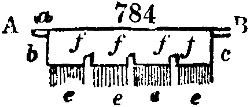
The fondu or rainbow style of paper-hangings, which I have referred to this place in the article Calico-printing, is produced by means of an assortment of oblong narrow tin pans, fixed in a frame, close side to side, each being about one inch wide, two inches deep, and eight inches long; the colours of the prismatic spectrum, red, orange, yellow, green, &c., are put, in a liquid state, successively in these pans; so that when the oblong brush A, B, with guide ledges a, b, c, is dipped into them across the whole of the parallel row at once, it comes out impressed with the different colours at successive points e, e, e, e, of its length, and is then drawn by the paper-stainer over the face of the woollen drumhead, or sieve of the swimming tub, upon which it leaves a corresponding series of stripes in colours, graduating into one another like those of the prismatic spectrum. By applying his block to the tear, the workman takes up the colour in rainbow hues, and transfers these to the paper. f, f, f, f show the separate brushes in tin sheaths, set in one frame.
At M. Zuber’s magnificent establishment in the antient château of Rixheim, near Mulhouse, where the most beautiful French papiers peints are produced, and where I was informed that no less than 3000 blocks are required for one pattern, I saw a two-colour calico machine employed with great advantage, both as to taste and expedition. Steam-charged cylinders were used to dry the paper immediately after it was printed, as the colours, not being so rapidly absorbed as they are by calico, would be very apt to spread.
The operations employed for common paper-hangings, are also used for making flock paper, only a stronger size is necessary for the ground. The flocks are obtained from the woollen cloth manufacturers, being cut off by their shearing machines, called lewises by the English workmen, and are preferred in a white state by the French paper-hanging makers, who scour them well, and dye them of the proper colours themselves. When they are thoroughly stove-dried, they are put into a conical fluted mill, like that for making snuff, and are properly ground. The powder thus obtained is afterwards sifted by a bolting-machine, like that of a flour mill, whereby flocks of different degrees of fineness are produced. These are applied to the paper after it has undergone all the usual printing operations. Upon the workman’s left hand, and in a line with his printing table, a large chest is placed for receiving the flock powders: it is seven or eight feet long, two feet wide at the bottom, three feet and a half at top, and from 15 to 18 inches deep. It has a hinged lid. Its bottom is made of tense calf-skin. This chest is called the drum; it rests upon four strong feet, so as to stand from 24 to 28 inches above the floor.
The block which serves to apply the adhesive basis of the velvet-powders, bears in relief only the pattern corresponding to that basis, which is formed with linseed oil, rendered drying by being boiled with litharge, and afterwards ground up with white lead. The French workmen call this mordant the encaustic. It is put upon the cloth which covers the inverted swimming tub, in the same way as the common colours are, and is spread with a brush by the tireur (corruptly styled tearer by some English writers). The workman daubs the blocks upon the mordant, spreads the pigment even with a kind of brush, and then applies it by impression to the paper. Whenever a sufficient surface of the paper has been thus covered, the child draws it along into the great chest, sprinkling the flock powder over it with his hands; and when a length of 7 feet is printed, he covers it up within the drum, and beats upon the calf-skin bottom with a couple of rods to raise a cloud of flock inside, and to make it cover the prepared portion of the paper uniformly. He now lifts the lid of the chest, inverts the paper, and beats its back lightly, in order to detach all the loose particles of the woolly powder.
By the operation just described, the velvet-down being applied every where of the same colour, would not be agreeable to the eye, if shades could not be introduced to relieve the pattern. To give the effect of drapery, for example, the appearance of folds must be introduced. For this purpose, when the piece is perfectly dry, the workman stretches it upon his table, and by the guidance of the pins in his blocks, he applies to the flock surface a colour in distemper, of a deep tint, suited to the intended shades, so that he dyes the wool in its place. Light shades are produced by applying some of his lighter water-colours.
Gold leaf is applied upon the above mordant, when nearly dry; which then forms a proper gold size; and the same method of application is resorted to, as for the ordinary gilding of wood. When the size has become perfectly hard, the superfluous gold leaf is brushed off with a dossil of cotton wool or fine linen.
The colours used by the paper-hangers are the following:—
1. Whites. These are either white-lead, good whitening, or a mixture of the two.
2. Yellows. These are frequently vegetable extracts; as those of weld, or of Avignon or Persian berries, and are made by boiling the substances with water. Chrome yellow is also frequently used, as well as the terra di Sienna and yellow ochre.
3. Reds are almost exclusively decoctions of Brazil wood.
4. Blues are either prussian blue, or blue verditer.
5. Greens, are Scheele’s green, a combination of arsenious acid, and oxide of copper; the green of Schweinfurth, or green verditer; as also a mixture of blues and yellows.
6. Violets are produced by a mixture of blue and red in various proportions, or they may be obtained directly by mixing a decoction of logwood with alum.
7. Browns, blacks, and grays. Umber furnishes the brown tints. Blacks are either common ivory or Frankfort black; and grays are formed by mixtures of prussian blue and Spanish white.
All the colours are rendered adhesive and consistent, by being worked up with gelatinous size or a weak solution of glue, liquefied in a kettle. Many of the colours are previously thickened, however, with starch. Sometimes coloured lakes are employed. See Lakes.
PAPER, MANUFACTURE OF. (Papeterie, Fr.; Papiermacherkunst, Germ.) This most useful substance, which has procured for the moderns an incalculable advantage over the antients, in the means of diffusing and perpetuating knowledge, seems to have been first invented in China, about the commencement of the Christian era, and was thence brought to Mecca, along with the article itself, about the beginning of the 8th century; whence the Arabs carried it, in their rapid career of conquest and colonization, to the coasts of Barbary, and into Spain, about the end of the 9th or beginning of the 10th century.
By other accounts, this art originated in Greece, where it was first made from cotton fibres, in the course of the tenth century, and continued there in common use during the next three hundred years. It was not till the beginning of the 14th century that paper was made from linen in Europe, by the establishment of a paper-mill in 1390, at Nuremberg in Germany. The first English paper-mill was erected at Dartford by a German jeweller in the service of Queen Elizabeth, about the year 1588. But the business was not very successful; in consequence of which, for a long period afterwards, indeed till within the last 70 years, this country derived its supplies of fine writing papers from France and Holland. Nothing places in a more striking light the vast improvement which has taken place in all the mechanical arts of England since the era of Arkwright, than the condition of our paper-machine factories now, compared with those on the Continent. Almost every good automatic paper mechanism at present mounted in France, Germany, Belgium, Italy, Russia, Sweden, and the United States, has either been made in Great Britain, and exported to these countries, or has been constructed in them closely upon the English models.
Till within the last 30 years, the linen and hempen rags from which paper was made, were reduced to the pasty state of comminution requisite for this manufacture by mashing them with water, and setting the mixture to ferment for many days in close vessels, whereby they underwent in reality a species of putrefaction. It is easy to see that the organic structure of the fibres would be thus unnecessarily altered, nay, frequently destroyed. The next method employed, was to beat the rags into a pulp by stamping rods, shod with iron, working in strong oak mortars, and moved by water-wheel machinery. So rude and ineffective was the apparatus, that forty pairs of stamps were required to operate a night and a day, in preparing one hundred weight of rags. The pulp or paste was then diffused through water, and made into paper by methods similar to those still practised in the small hand-mills.
About the middle of the last century, the cylinder or engine mode, as it is called, of comminuting rags into paper pulp, was invented in Holland; which was soon afterwards adopted in France, and at a later period in England.
The first step in the paper manufacture, is the sorting of the rags into four or five qualities. They are imported into this country chiefly from Germany, and the ports of the Mediterranean. At the mill they are sorted again more carefully, and cut into shreds by women. For this purpose a table frame is covered at top with wire cloth, containing about nine meshes to the square inch. To this frame a long steel blade is attached in a slanting position, against whose sharp edge the rags are cut into squares or fillets, after having their dust thoroughly shaken out through the wire cloth. Each piece of rag is thrown into a certain compartment of a box, according to its fineness; seven or eight sorts being distinguished. An active woman can cut and sort nearly one cwt. in a day.
The sorted rags are next dusted in a revolving cylinder surrounded with wire cloth, about six feet long, and four feet in diameter, having spokes about 20 inches long, attached at right angles to its axis. These prevent the rags from being carried round with the case, and beat them during its rotation; so that in half an hour, being pretty clean, they are taken out by the side door of the cylinder, and transferred to the engine, to be first washed, and next reduced into a pulp. For fine paper, they should be previously boiled for some time in a caustic lye, to cleanse and separate their filaments.
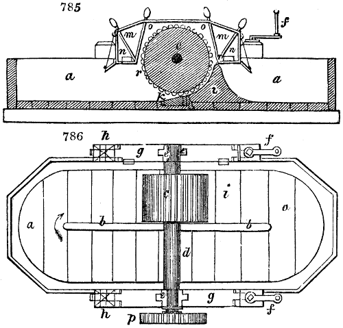
The construction of the stuff-engine is represented in figs. 785, 786. Fig. 785. is the longitudinal section, and fig. 786. the plan of the engine. The large vat is an oblong cistern rounded at the angles. It is divided by the partition b, b, and the whole inside is lined with lead. The cylinder c, is made fast to the spindle d, which extends across the engine, and is put in motion by the pinion p, fixed to its extremity. The cylinder is made of wood, and furnished with a number of blades or cutters, secured to its circumference, parallel to the axis, and projecting about an inch above its surface. Immediately beneath the cylinder a block of wood k is placed. This is mounted with cutters like those of the cylinder, which in their revolution pass very near to the teeth of the block, but must not touch it. The distance between these fixed and moving blades is capable of adjustment by elevating or depressing the bearings upon which the necks e, e, of the shaft are supported. These bearings rest upon two levers g, g, which have tenons at their ends, fitted into upright mortises, made in short beams h, h, bolted to the sides of the engine. The one end of the levers g, g, is movable, while the other end is adapted to rise and fall upon bolts in the beams h, h, as centres. The front lever, or that nearest to the cylinder c, is capable of being elevated or depressed, by turning the handle of a screw (not seen in this view), which acts in a nut fixed to the tenon of g, and comes up through the top of the beam h, upon which the head of the screw takes its bearing. Two brasses are let into the middle of the levers g, g, and form the bearings for the shaft of the engine to turn upon. The above-mentioned vertical screw is used to raise or lower the cylinder, and cause it to cut coarser or finer, by enlarging or diminishing the space between the fixed cutters in the block and those in the cylinder.
To the left hand of i, fig. 785., is a circular breasting made of boards, and covered with sheet lead; it is curved to fit the cylinder very truly, and leaves but very little space between the teeth and breasting; at its bottom, the block k is fixed. The engine is supplied with water from a pump, by a pipe, which delivers it into a small cistern, near to and communicating with the engine. A stopcock cuts off or regulates the supply of water at pleasure, and a grating covered with hair-cloth is fixed across that small cistern, to intercept any filth that may be floating in the water; in other cases a flannel bag is tied round the nose of the stopcock, to act as a filter.
The rags being put into the engine filled with water, are drawn by the rapid rotation of the cylinder between the two sets of cutters, whereby they are torn into the finest filaments, and by the impulsion of the cylinder they are floated over the top of the breasting upon the inclined plane. In a short time more rags and water are raised into that part of the engine vat. The tendency in the liquid to maintain an equilibrium, puts the whole contents of the cistern in slow motion down the inclined plane, to the left hand of i, and round the partition b, b, (see the arrow), whereby the rags come to the cylinder again in the space of about 20 minutes; so that they are repeatedly drawn out and separated in all directions till they are reduced to the appearance of a pulp.
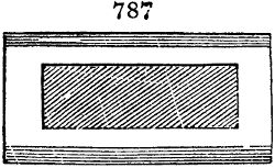
This circulation is particularly useful, by turning over the rags in the engine, causing them to be presented to the cutter at different angles every time; otherwise, as the blades always act in one direction, the comminution would not be so complete. The cutting is performed as follows: The teeth of the block are set somewhat obliquely to the axes of the cylinder, as shown by fig. 787.; but the teeth of the cylinder c itself are set parallel to its axis; therefore the cutting edges meet at a small angle, and come in contact, first at the one end, and then towards the other, by successive degrees, so that any rags coming between them, are torn as if between the blades of a pair of forceps. Sometimes the blades k in the block are bent to an angle in the middle, instead of being straight and inclined to the cylinder. These are called elbow plates; their two ends being inclined in opposite directions to the axis of the cylinder. In either case, the edges of the plates of the block cannot be straight lines, but must be curved, to adapt themselves to the curve which a line traced on the cylinder will necessarily have. The plates or blades are united by screwing them together, and fitting them into a cavity cut into the wooden block k. Their edges are bevelled away upon one side only.
The block is fixed in its place by being made dovetailed, and truly fitted into the bottom of the cistern, so that the water will not leak through its junction. The end of it comes through the woodwork of the chest, and projects to a small distance on its outside, being kept in its place by a wedge. By withdrawing this wedge, the block becomes loose, and can be removed in order to sharpen the cutters, as occasion may be. This is done at a grindstone, after detaching the plates from each other.
The cutters of the cylinder, are fixed into grooves, cut in the wood of the cylinder, at equal distances asunder, round its periphery, in a direction parallel to its axis. The number of these grooves is twenty, in the machine here represented. For the washer, each groove has two cutters put into it; then a fillet of wood is driven fast in between them, to hold them firm; and the fillets are secured by spikes driven into the solid wood of the cylinder. The beater is made in the same manner, except that each groove contains three bars and two fillets.
In the operation of the cylinder, it is necessary that it should be enclosed in a case, or it would throw all the water and rags out of the engine, in consequence of its great velocity. This case is a wooden box m, m, fig. 785., enclosed on every side except the bottom; one side of it rests upon the edge of the vat, and the other upon the edge of the partition b, b, fig. 786. The diagonal lines m, r, represent the edges of wooden frames, which are covered with hair or wire cloth, and immediately behind these the box is furnished with a bottom and a ledge towards the cylinder, so as to form a complete trough. The square figures under n, n, in fig. 785., show the situation of two openings or spouts through the side of the case, which conduct to flat lead-pipes, one of which is seen near the upper g in fig. 786., placed by the side of the vat; the beam being cut away from them. These are waste pipes to discharge the foul water from the engine; because the cylinder, as it turns, throws a great quantity of water and rags up against the sieves; the water goes through them, and runs down to the trough under n, n, and thence into the ends of the flat leaden pipes, through which it is discharged. o, o, fig. 785., are grooves for two boards, which, when put down in their places, cover the hair sieves, and stop the water from going through them, should it be required in the engine. This is always the case in the beating engines, and therefore they are seldom provided with these waste pipes, or at most on one side only; the other side of the cover being curved to conform to the cylinder. Except this, the only difference between the washing engine and the beater, is that the teeth of the latter are finer, there being 60 instead of 40 blades in the periphery; and it revolves quicker than the washer, so that it will tear out and comminute those particles which pass through the teeth of the washer. In small mills, when the supply of water is limited, there is frequently but one engine, which may be used both for washing and beating, by adjusting the screw so as to let the cylinder down and make its teeth work finer. But the system in all considerable works, is to have two engines at least, or four if the supply of water be great. The power required for a 5 or 6 vat mill, is about 20 horses in a water-wheel or steam engine.
In the above figures only one engine is shown, namely, the finisher; there is another, quite similar, placed at its end, but on a level with its surface, which is called the washer, in which the rags are first worked coarsely with a stream of water, running through them to wash and open their fibres; after this washing they are called half-stuff, and are then let down into the bleaching engine, and next into the beating engine, above described.
By the arrangements of the mill gearing, the two cylinders of the washer and beater engines make from 120 to 150 revolutions per minute, when the water-wheel moves with due velocity. The beating engine is always made to move, however, much faster than the washing one, and nearly in the ratio of the above numbers.
The vibratory noise of a washing engine is very great; for when it revolves 120 times per minute, and has 40 teeth, each of which passes by 12 or 14 teeth in the block at every revolution, it will make nearly 60,000 cuts in a minute, each of them sufficiently loud to produce a most grating growling sound. As the beater revolves quicker, having perhaps 60 teeth, instead of 40, and 20 or 24 cutters in the block, it will make 180,000 cuts in a minute. This astonishing rapidity produces a coarse musical humming, which may be heard at a great distance from the mill. From this statement, we may easily understand how a modern engine is able to turn out a vastly greater quantity of paper pulp in a day than an old mortar machine.
The operation of grinding the rags requires nice management. When first put into the washing engine they should be worked gently, so as not to be cut, but only powerfully scrubbed, in order to enable the water to carry off the impurities. This effect is obtained by raising the cylinder upon its shaft, so that its teeth are separated considerably from those of the block. When the rags are comminuted too much in the washer, they would be apt to be carried off in part with the stream, and be lost; for at this time the water-cock is fully open. After washing in this way for 20 or 30 minutes, the bearings of the cylinder are lowered, so that its weight rests upon the cutters. Now the supply of water is reduced, and the rags begin to be torn, at first with considerable agitation of the mass, and stress upon the machinery. In about three or four hours, the engine comes to work very smoothly, because it has by this time reduced the rags to the state of half-stuff. They are then discharged into a large basket, through which the water drains away.
The bleaching is usually performed upon the half-stuff. At the celebrated manufactory of Messrs. Montgolfier, at Annonay, near Lyons, chlorine gas is employed for this purpose with the best effect upon the paper, since no lime or muriate of lime can be thus left in it; a circumstance which often happens to English paper, bleached in the washing engine by the introduction of chloride of lime among the rags, after they have been well washed for three or four hours by the rotation of the engine. The current of water is stopped whenever the chloride of lime is put in. From 1 to 2 pounds of that chemical compound are sufficient to bleach 1 cwt. of fine rags, but more roust be employed for the coarser and darker coloured. During the bleaching operation the two sliders o, o, fig. 785., are put down in the cover of the cylinder, to prevent the water getting away. The engine must be worked an hour longer with the chloride of lime, to promote its uniform operation upon the rags. The cylinder is usually raised a little during this period, as its only purpose is to agitate the mass, but not to triturate it. The water-cock is then opened, the boards m, m are removed, and the washing is continued for about an hour, to wash the salt away; a precaution which ought to be better attended to than it always is by paper manufacturers.
The half-stuff thus bleached, is now transferred to the beating engine, and worked into a fine pulp. This operation takes from 4 to 5 hours, a little water being admitted from time to time, but no current being allowed to pass through, as in the washing engine. The softest and fairest water should be selected for this purpose; and it should be administered in nicely regulated quantities, so as to produce a proper spissitude of stuff for making paper.
For printing paper, the sizing is given in the beating engine, towards the end of its operation. The size is formed of alum in fine powder, ground up with oil; of which mixture about a pint and a half are thrown into the engine at intervals, during the last half-hour’s beating. Sometimes a little indigo blue or smalt is also added, when a peculiar bloom colour is desired. The pulp is now run off into the stuff chest, where the different kinds are mixed; whence it is taken out as wanted. The chest is usually a rectangular vessel of stone or wood lined with lead, capable of containing 300 cubic feet at least, or 3 engines full of stuff. Many paper-makers prefer round chests, as they admit of rotatory agitators.
When the paper is made in single sheets, by hand labour, as in the older establishments, a small quantity of the stuff is transferred to the working-vat by means of a pipe, and there diluted properly with water. This vat is a vessel of stone or wood, about 5 feet square, and 4 deep, with sides somewhat slanting. Along the top of the vat a board is laid, with copper fillets fastened lengthwise upon it, to make the mould slide more easily along. This board is called the bridge. The maker stands on one side; and has to his left hand a smaller board, one end of which is made fast to the bridge, while the other rests on the side of the vat. In the bridge opposite to this, a nearly upright piece of wood, called the ass, is fastened. In the vat there is a copper, which communicates with a steam pipe to keep it hot; there is also an agitator, to maintain the stuff in a uniform consistence.
The moulds consist of frames of wood, neatly joined at the corners, with wooden bars running across, about an inch and a half apart. Across these, in the length of the moulds, the wires run, from fifteen to twenty per inch. A strong raised wire is laid along each of the cross bars, to which the other wires are fastened; this gives the laid paper its ribbed appearance.
The water-mark is made by sewing a raised piece of wire in the form of letters, or any figured device, upon the wires of the mould, which makes the paper thinner in these places. The frame-work of a wove mould is nearly the same; but instead of sewing on separate wires, the frame is covered with fine wire cloth, containing from 48 to 64 meshes per inch square. Upon both moulds a deckel, or movable raised edge-frame, is used; which must fit very neatly, otherwise the edges of the paper will be rough.
A pair of moulds being laid upon the bridge, the workman puts on the deckel, brings the mould into a vertical position, dips it about half way down into the stuff before him, then turning it into a horizontal position, covers the mould with the stuff and shakes it gently. This is a very delicate operation; for if the mould be not held perfectly level, one part of the sheet will be thicker than another. The sheet thus formed has, however, no coherence; so that by turning the mould, and dipping the wire cloth surface in the vat, it is again reduced to pulp if necessary. He now pushes the mould along the small board to the left, and removes the deckel. Here another workman called the coucher receives it, and places it at rest upon the ass, to drain off some of the water. Meanwhile the vat-man puts the deckel upon the other mould, and makes another sheet. The coucher stands to the left side of the vat, with his face towards the vat-man or maker, on his right is the press furnished with felt cloths, or porous flannels; a three-inch-thick plank lies before him on the ground. On this he lays a cushion of felts, and on this another felt; he then turns the paper wire mould, and presses it upon the felt, where the sheet remains. He now returns the mould by pushing it along the bridge. The maker has by this time another sheet ready for the coucher; which, like the preceding, is laid upon the ass, and then couched or inverted upon another felt, laid down for the purpose.
In this way, felts and paper are alternately stratified, till a heap of six or eight quires is formed, which is from 15 to 18 inches high. This mass is drawn into the press, and exposed to a force of 100 tons or upwards. After it is sufficiently compressed, the machine is relaxed, and the elasticity of the flannel makes the rammer descend (if a hydraulic press be used) with considerable rapidity. The felts are then drawn out on the other side by an operative called a layer, who places each felt in succession upon one board, and each sheet of paper upon another. The coucher takes immediate possession of the felts for his further operations.
Two men at a vat, and a boy as a layer or lifter, can make about 6 or 8 reams in 10 hours. In the evening the whole paper made during the day, is put into another press, and subjected to moderate compression, in order to get quit of the mark of the felt, and more of the water. Next day it is all separated, a process called parting, and being again pressed, is carried into the loft. Fine papers are often twice parted and pressed, in order to give them a proper surface.
The next operation is the drying, which is performed in the following way. Posts about 10 or 12 feet high are erected at the distance of ten feet from each other, and pierced with holes six inches apart; two spars with ropes stretched between them, at the distance of 5 inches from one another, called a treble or tribble, are placed about 5 feet high between these posts, supported by pins pushed into the holes in the posts. The workman takes up 4 or 8 sheets of paper, and puts them upon a piece of wood in the form of a T; passing this T between the ropes, he shifts the sheets upon them, and proceeds thus till all the ropes are full. He then raises the treble, and puts another in its place, which he fills and raises in like manner. Nine or ten trebles are placed in every set of posts. The sides of the drying-room have proper shutters, which can be opened to any angle at pleasure.
When the paper is dry, it is taken down, and laid neatly in heaps to be sized. Size is made of pieces of skin, cut off by the curriers before tanning, or sheep’s feet, or any other matter containing much gelatine. These substances are boiled in a copper to a jelly; to which, when strained, a small quantity of alum is added. The workman then takes about 4 quires of paper, spreads them out in the size properly diluted with water, taking care that they be equally moistened. This is rather a nice operation. The superfluous size is then pressed out, and the paper is parted into sheets. After being once more pressed, it is transferred to the drying-room, but must not be dried too quickly. Three days are required for this purpose. When the paper is thoroughly dry, it is carried to the finishing-house, and is again pressed pretty hard. It is then picked by women with small knives, in order to take out the knots, and separate the perfect from the imperfect sheets. It is again pressed, given to the finisher, to be counted into reams, and done up. These reams are compressed, tied up, and sent to the warehouse for sale. A good finisher can count 200 reams, or 96,000 sheets in a day.
Hot pressing is executed by placing a sheet of paper between two smoothed pasteboards, alternately, and between every 50 pasteboards a heated plate of iron, and subjecting the pile to the press. This communicates a fine smooth surface to writing-paper.
The grain of the paper is often disfigured by the felts, when they are too much used, or when the loose fibres do not cover the twisted thread. The two sides of the felt are differently raised, and that on which the fibres are longest is applied to the sheets which are laid down. As the felts have to resist the reiterated action of the press, their warp should be made stout, of long combed wool, and well twisted. The woof, however, should be of carded wool, and spun into a soft thread, so as to render the fabric spongy, and capable of imbibing much water.
This operose and delicate process of moulding the sheets of paper by hand, has for nearly thirty years past been performed, in many manufactories, by a machine which produces it in a continuous sheet of indefinite length which is afterwards cut into suitable sizes, by the Paper-cutting Machine.
In 1799, Louis Robert, then employed in the paper works of Essonne in France, contrived a machine to make paper of a great size, by a continuous motion, and obtained for it a patent for 15 years, with a sum of 8000 francs from the French government, as a reward for his ingenuity. The specification of this patent is published in the second volume of Brevets d’Invention expirés. M. Leger-Didot, then director of the said works, bought Robert’s machine and patent for 25,000 francs, to be paid by instalments. Having become proprietor of this machine, which, though imperfect, contained the germ of a valuable improvement in paper-making, M. Didot came over with it to England, where he entered into several contracts for constructing and working it.
Meanwhile M. L. Didot having failed to fulfil his obligations to Robert, the latter instituted a law-suit, and recovered possession of his patent by a decision dated 23d June, 1810. Didot then sent over to Paris the Repertory of Arts, for Sept. 1808, which contained the specification of the English patent, with instructions to a friend to secure the improved machines described in it, by a French patent. The patent was obtained, but became inoperative in consequence of M. L. Didot failing to return to France, as he had promised, so as to mount the patent machine within the two years required by the French patent law. It was not till 1815, that M. Calla, machine-maker at Paris, constructed the paper apparatus known in England by the name of Fourdrinier’s, and which, on the authority of the Dictionnaire Technologique, was very imperfect in comparison of an English-made machine imported about that time into France. La construction de ces machines, qui n’offre pourtant rien de difficile, est restée jusqu’à ce jour exclusivement dans les mains des Anglais, is the painful acknowledgment made in 1829, for his countrymen, by the author of the elaborate article Papeterie in that national work. If there be nothing difficult in the construction of these machines, the French mechanicians ought to be ashamed of forcing their countrymen to seek the sole supply of them in England; for the principal paper works in France, as those of MM. Canson, Montgolfier, Thomas Varenne, Firmin Didot, Delcambre, De Maupeon, &c., are mounted with English-made machines.
The following, for example, are a few of the paper-mills in France which are mounted with the self-acting machines of Messrs. Bryan Donkin & Co.:—
Messrs. Canson, at Annonay.
M. de la Place, at Jean d’Heures, Bar-le-duc.
Société anonyme, at Sainte Marie, under M. Delatouche.
Echarcon près Mennecy, (Seine et Oise).
Firmin Didot, Mesnil sur l’Estrée.
M. F. M. Montgolfier, à Annonay.
Muller, Bouchard, Ondin and Co’s., at Gueures, near Dieppe.
MM. Richard et Comp. à Plainfoing.
M. Callot-Bellisle; Vieuze et Chantoiseau.
M. Bechétaile, near St. Etienne, at Bourg Argental.
It deserves particularly to be remarked, to the honour of English mechanism, that the proprietors of the first five of the above works received gold medals at the last exposition of their papers at the Louvre, and all the rest received medals either of silver or bronze.[37]
The following is a true narrative of the rise and progress of the paper automaton.
M. Leger Didot, accompanied by Mr. John Gamble, an Englishman who had resided for several years in Paris, obtained permission from the French government, in 1800, to carry over the small working model of Robert’s continuous machine, with the view of getting the benefit of English capital and mechanical skill to bring it into an operative state upon the great scale. Fortunately for the vigorous development of this embryo project, which had proved an abortion in France, they addressed themselves on the one hand, to a mercantile firm equally opulent and public spirited, and on the other, to engineers distinguished for persevering energy and mechanical resource. A first patent was granted to Mr. Gamble on the 20th of April 1801, and a second, for certain improvements upon the former, on the 7th of June 1803. In January 1804, Mr. Gamble, for certain considerations, assigned these two patents to Messrs. Henry and Sealy Fourdrinier, the house above alluded to, who were at that period, and for several years afterwards, the most considerable stationers and paper-makers in Great Britain. By an act of parliament passed on the 4th of August 1807, Mr. Gamble’s privilege of 14 years from April 1801, was prolonged to 15 years after the date of the act, being an extension of about 7 years upon the original patent.
The proprietors showed good reasons, in the enormous expense of their experiments, and the national importance of the object, why the patent should have been extended 14 years from the latter date, and would have obtained justice from parliament in this respect, but for an unworthy artifice of Lord Lauderdale in the House of Lords. “He, and he only, was the person who took the objection,” and, by introducing a regulation in a standing order of the House of Lords, that none but the original inventor should have an extension, though Mr. H. Fourdrinier was the inventor substantially of the operative machine, he defeated the honourable intentions of his brother peers, whose committee said, “We will give seven years, and Mr. Fourdrinier may apply again, if it should turn out that the seven years that we propose to give to Mr. Fourdrinier should not give sufficient time to afford any chance of his receiving any remuneration for the expense that he has incurred in introducing this invention.” The bill passed in the House of Commons for 14 years, but it was limited by this ruse of Lord Lauderdale to 7, “who put the standing order upon the books (of the upper house) which prevented Messrs. Fourdrinier from having any benefit from the invention.”[38]
In February 1808, Mr. Gamble, after losing both his time and money savings during eight years of irksome diligence, assigned over to Messrs. Fourdrinier the whole right of his share in the patent to which he was entitled under the act of parliament.
Dartford in Kent, which had been long conspicuous as the seat of a good manufactory of paper and paper moulds, was selected by the proprietors of the patent as the fittest place for realizing their plans; and happily for them it possessed, in Mr. Hall’s engineering establishment, every tool requisite for constructing the novel automaton, and in his assistant Mr. Bryan Donkin, a young and zealous mechanist, who, combining precision of workmanship with fertility of invention, could turn his local advantages to the best account. To this gentleman, aided by the generous confidence of Messrs. Fourdrinier, the glory of rearing to a stately manhood the helpless bantling of M. L. Didot is entirely due. In 1803, after nearly three years of intense application, he produced a self-acting machine for making an endless web of paper, which was erected at St. Neot’s, under the superintendence of Mr. Gamble, and performed in such a manner as to surprise every beholder.
Since that important era Mr. Donkin has steadily devoted his whole mind and means to the progressive improvement of this admirable apparatus; and has, by the unfailing regularity, precision, promptitude, and productiveness of its work, earned for himself a place along with Watt, Wedgewood, and Arkwright, in the temple of mechanical fame.
“La France,” says a late official eulogist of her arts, and interpreter of her sentiments, “ne craint plus la rivalité des autres peuples pour la fabrication des divers genres de papiers et de cartons.”[39] After this boast, one would not expect to hear him immediately confess that in 1823 his country possessed only one manufactory of the papier continu, containing one of the Fourdrinier machines made at London by Mr. Donkin, for M. Canson, at Vidalon-les-Annonay; that in 1827 there were only 4 of these machines in France, and that in 1834 there were not many more than a dozen. He justly observes, that “this mode being more economical, more rapid, and more powerful, will become henceforth the only one which can be practised without loss. Then will disappear the antient system of hand-work, which likewise involved the inconveniences, we may say dangers, resulting from combinations among the operatives. The machine-made papers possess many advantages: they can receive, so to speak, unlimited dimensions; they preserve a perfectly uniform thickness throughout all their length; they may be fabricated in every season of the year; nor do they require to be sorted, trimmed, and hung up in the drying-house, operations which occasioned great waste, amounting to no less than one defective sheet out of every five. The continuous paper at one time retained the impression of the wire-wove web on its under side; a defect from which it has been freed by a pressure apparatus of Mr. Donkin, recently imported from England by M. Delatouche.”
It appears from documents presented to a committee of the House of Lords in 1807, that the Messrs. Fourdrinier had, by that time, withdrawn from their stationery business the large sum of 60,000l., to further the object of their patent; so many difficulties did they encounter in bringing the machinery to its then comparatively complete state, and so little encouragement or support did they receive from the paper manufacturers throughout the kingdom.
The patentees laid a statement before the public in 1806, containing the following comparative estimate of the expense attending seven vats, and that attending a machine employed upon paper sized in the engine, performing the same quantity of work as seven vats, at the rate of 12 hours daily.
A MACHINE.
Day. Week. Month. Year.
s. d. £ s. d. £ s. d. £ s. d.
2 Journeymen 3 6 2 2 0 8 8 0 109 4 0
2 Ditto 2 6 1 10 0 6 0 0 78 0 0
2 Finishers 3 6 2 2 0 8 8 0 109 4 0
2 Dry workers 3 6 2 2 0 8 8 0 109 4 0
Parters (none)
Fire (none)
Felting 24 0 0
Washing, ditto 5 0 0
Wire 200 0 0
1 Man, to keep in repair the mill and machine 100 0 0
Total 9 7 16 0 31 4 0 734 12 0
£ s. d.
Expense of 7 vats per annum (see next page), is 2,604 12 0
A machine doing 7 vats’ work, is, per annum 734 12 0
Balance saved by the machine per annum £1,870 0 0
N. B.—There are other advantages, to the amount of full 400l. per annum, of which manufacturers are well aware, although not taken into this calculation.
SEVEN VATS.
Day. Week. Month. Year.
s. d. £ s. d. £ s. d. £ s. d.
7 Vatmen, at 3 3 6 16 6 27 6 0 354 18 0
7 Couchers 3 1 6 9 6 25 18 0 336 14 0
7 Layers 3 1 6 9 6 25 18 0 336 14 0
3 Finishers 4 0 3 12 0 14 8 0 187 4 0
6 Dry-workers 3 1 5 11 0 22 4 0 288 12 0
3 Men to go to press, &c. 2 6 2 5 0 9 0 0 117 0 0
7 Parters (women) 1 4 2 16 0 11 4 0 145 12 0
Fire 7 0 0 28 0 0 364 0 0
Felting 140 0 0
Washing ditto, oil, soap, fire, &c. 1 11 6 6 6 0 81 18 0
Moulds 140 0 0
1 Man, and expenses of repairing, in keeping in order 7 vats, vat-presses, &c. 112 0 0
Total 41 persons. 42 11 0 170 4 0 2,604 0 0
In the same statement, it was shown that the expense of making paper by hand is 16s. per cwt., whereas by their machine it is only 3s. 9d.; so that upon 432,000 cwts. the quantity annually made in Great Britain and Ireland (as founded upon the fact that one vat can make 480 cwts. of paper, and that there were 900 vats in the kingdom), the annual saving by the machine would be 264,600l., or 345,600l. - 81,000l.
In a second statement laid before the public in 1807, the patentees observe that their recently improved machine, from its greater simplicity, may be erected at a considerably reduced expense. “Mr. Donkin, the engineer, will engage to furnish machines of the dimensions specified below, with all the present improvements, at the prices specified below.
Inches. If driven by straps. £
3 or 4 vats 30 between the deckles 715
6 ditto 40 ditto ditto 845
8 ditto 44 ditto ditto 940
12 ditto 54 ditto ditto 995
If driven by wheels.
3 or 4 vats 30 between the deckles 750
6 ditto 40 ditto ditto 880
8 ditto 44 ditto ditto 980
12 ditto 54 ditto ditto 1,040
“Instead of 5 men, formerly employed upon 1 machine, 3 are now (in 1813) fully sufficient, without requiring that degree of attention and skill which were formerly indispensable.
“In 1806 the machine was capable of doing the work of 6 vats in twelve hours; it is, however, now capable of doing double that quantity, at one-fourth of the expense. For by the various improvements enumerated above, the consumption of wire is reduced nearly one-half, and lasts above double the time; the quantity of paper produced is doubled; and, taking into consideration the work which is now performed by the men over and above their immediate attendance upon the machine, it may be fairly stated, that the number of men is reduced to one-half; consequently the expense of wire and labour is reduced to one-fourth of what it was.
“The other advantages incidental to the nature of the process of making paper by this machine, may be classed in the following order:—
“1st. That the paper is much superior in strength, firmness, and appearance, to any which can be made by hand of the same material.
“2d. It requires less drying, less pressing and parting, and consequently comes sooner to market; for it receives a much harder pressure from the machine than can possibly be given by any vat press, and is therefore not only drier, but, on account of the closeness and firmness of texture, even the moisture which remains is far sooner evaporated, on exposure to the air, than it would be from the more spungy or bibulous paper made by hand.
“The superior pressure, and the circumstance of one side of the paper passing under the polished surface of one of the pressing rollers, contribute to that smoothness which in hand-made papers can only be obtained by repeated parting and pressing; consequently a great part of the time necessarily spent in these operations is saved, and the paper sooner finished and ready for market.
“3dly. The quantity of broken paper and retree is almost nothing compared with what is made at the vats.
“4th. The machine makes paper with cold water.
“5th. It is durable, and little subject to be out of repair. The machine at Two Waters, in Hertfordshire, for the last three years, has not cost 10l. a year in repairs.
“6th. As paper mills are almost universally wrought by streams, which vary considerably in their power from time to time, there will result from this circumstance a very important advantage in the adoption of the machine. The common paper mill being limited by its number of vats, no advantage can be taken of the frequent accessions of power which generally happen in the course of the year, but, on the contrary, as scarcely any mills are capable of preparing stuff for twelve vats, every accession of power to the mill, where a machine is employed, will increase its produce without any additional expense.
“7th. The manufacturer can suspend or resume his work at pleasure; and he is besides effectually relieved from the perplexing difficulties and loss consequent upon the perpetual combinations for the increase of wages.”
It is a lamentable fact, that the attention required to mature this valuable invention, and the large capital which it absorbed, led ultimately to the bankruptcy of this opulent and public-spirited company; after which disaster no patent dues were collected, though twelve suits in Chancery were instituted; these being mostly unsuccessful, on account of some paltry technical objections made to their well-specified patent, by that unscientific judge Lord Tenterden. The piratical tricks practised by many considerable paper-makers against the patentees are humiliating to human nature in a civilized and soi disant Christian community. Many of them have owned, since the bankruptcy of the house removed the fear of prosecution, that they owed them from 2000l. to 3000l. apiece.
Nothing can place the advantage of the Fourdrinier machine in a stronger point of view, than the fact of there being 280 of them now at work in the United Kingdom, making collectively 1600 miles of paper, of from 4 to 5 feet broad, every day; that they have lowered the price of paper 50 per cent., and that they have increased the revenue, directly and indirectly, by a sum of probably 400,000l. per annum. The tissue paper made by the machine is particularly useful for communicating engraved impressions to pottery ware; before the introduction of which there was but a miserable substitute. Messrs. R. and J. Clewes, of Cobridge potteries, in a letter to Messrs. Fourdrinier, state, “that had not an improvement taken place in the manufacture of paper, the new style of engraving would have been of no use, as the paper previously used was of too coarse a nature to draw from the fair engravings any thing like a clear or perfect impression; and the Staffordshire potteries, in our opinion, as well as the public at large, are deeply indebted to you for the astonishing improvement that has recently taken place, both as regards china and earthenware, more particularly the latter.” The following rates of prices justify the above statement:—
1814. 1822. 1833.
s. d. s. d. s. d.
Demy pottery tissue 12 0 9 6 7 0
Royal 16 3 12 0 8 9
“We have adopted a new mode of printing on china and earthenware, which, but for your improved system of making tissue paper, must have utterly failed; our patent machine requiring the paper in such lengths as were impossible to make on the old plan. On referring to our present stock, we find we have one sheet of your paper more than 1200 yards long. Signed, Machin and Potts; Burslem, February 25th, 1834.”
I have had the pleasure of visiting more than once the mechanical workshops of Messrs. Bryan Donkin and Co. in Bermondsey, and have never witnessed a more admirable assortment of exquisite and expensive tools, each adapted to perform its part with despatch and mathematical exactness, though I have seen probably the best machine factories of this country and the Continent. The man of science will appreciate this statement, and may perhaps be surprised to learn that the grand mural circle of 7 feet diameter, made by Troughton, for the Royal Observatory of Greenwich, was turned with final truth upon a noble lathe in the said establishment. It has supplied no fewer than 133 complete automatic paper machines, each of a value of from 1200l. to 2000l., to different manufactories, not only in the United Kingdom, but in all parts of the civilized world; as mentioned in the second paragraph of the present article. Each machine is capable of making, under the impulsion of any prime mover, all unmatched by a human eye, and unguided by a human hand, from 20 to 50 feet in length, by 5 feet broad, of most equable paper in one minute. Of paper of average thickness, it turns off 30 feet.
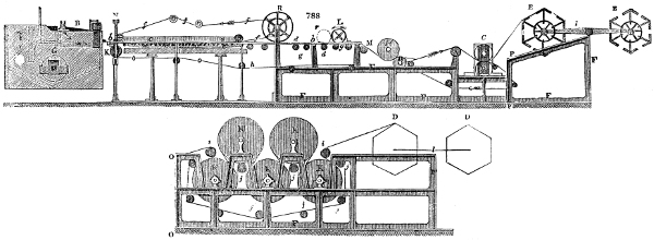
Fig. 788 enlarged (288 kB)
Fig. 788. is an upright longitudinal section, representing the machine in its most complete state, including the drying steam cylinders, and the compound channelled rollers of Mr. Wilks, subsequently to be described in detail. The figure in the upper line shows it all in train, when the paper is to be wound up wet upon the reels E, E, which being movable round the centre l of a swing-bar, are presented empty, time about, to receive the tender web. The figure in the under line contains the steam or drying cylinders; the points O, O, of whose frame, replace, at the points P, P, the wet-reel frame, F, F, P.
A is the vat, or receiver of pulp from the stuff-chest.
B is the knot strainer of Ibotson (p. 936.), to clear the pulp before passing on to the wire.
G is the hog, or agitator in the vat. The arrows show the course of the currents of the pulp in the vat.
I is the apron, or receiver of the water and pulp which escape through the endless wire, and which are returned by a scoop-wheel into the vat.
b is the copper lip of the vat, over which the pulp flows to the endless wire, on a leathern apron extending from this lip to about 9 inches over the wire, to support the pulp and prevent its escaping.
c, c are the bars which bear up the small tube rollers that support the wire.
d, d are ruler bars, to support the copper rollers over which the wire revolves.
K is the breast roller, round which the endless wire turns.
N is the point where the shaking motion is given to the machine.
M is the guide roller, having its pivots movable laterally to adjust the wire and keep it parallel.
L is the pulp roller, or “dandy,” to press out water, and to set the paper. r, is the place of the second, when it is used.
H is the first or wet press, or couching rollers; the wire leaves the paper here, which latter is couched upon the endless felt p; and the endless wire o returns, passing round the lower couch roller. By Mr. Donkin’s happy invention of placing these rollers obliquely, the water runs freely away, which it did not do when their axes were in a vertical line.
e, e are the deckles, which form the edges of the sheet of paper, and prevent the pulp passing away laterally. They regulate the width of the endless sheet.
f, f are the revolving deckle straps.
R is the deckle guide, or driving-pulley.
g, g are tube rollers, over which the wire passes, which do not partake of the shaking motion; and,
h, h are movable rollers for stretching the wire, or brass carriages for keeping the rollers g, g in a proper position.
C is the second press, or dry press, to expel the water in a cold state.
K, K, &c., in the view of the lower line, are the steam cylinders for drying the endless sheet.
i, i are rollers to convey the paper.
j, j are rollers to conduct the felt; which serves to support the paper, and prevent it wrinkling or becoming cockled.
D, D are the hexagonal expanding reels for the steam-dried paper web, one only being used at a time, and made to suit different sizes of sheets. l is their swing fulcrum.
F, F, F, F, is the frame of the machine.
The deckle straps are worthy of particular notice in this beautiful machine. They are composed of many layers of cotton tape, each one inch broad, and together one half-inch thick, cemented with caoutchouc, so as to be at once perfectly flexible and water-tight.
The upper end of each of the two carriages of the roller L is of a forked shape, and the pivots of the roller are made to turn in the cleft of the forked carriages in such a manner, that the roller may be prevented from having any lateral motion, while it possesses a free vibratory motion upwards and downwards; the whole weight of the roller L being borne by the endless web of woven wire.
The greatest difficulty formerly experienced in the paper manufacture upon the continuous system of Fourdrinier, was to remove the moisture from the pulp, and condense it with sufficient rapidity, so as to prevent its becoming what is called water-galled, and to permit the web to proceed directly to the drying cylinders. Hitherto no invention has answered so well in practice to remove this difficulty as the channelled and perforated pulp rollers or dandies of Mr. John Wilks, the ingenious partner of Mr. Donkin; for which a patent was obtained in 1830. Suppose one of these rollers (see L, in fig. 788., and M, M, in fig. 793.,) is required for a machine which is to make paper 54 inches wide, it must be about 60 inches long, so that its extremities (see figs. 789. and 790.) may extend over or beyond each edge of the sheet of paper upon which it is laid. Its diameter may be 7 inches. About 8 grooves, each 1-16th of an inch wide, are made in every inch of the tube; and they are cut to half the thickness of the copper, with a rectangularly shaped tool. A succession of ribs and grooves are thus formed throughout the whole length of the tube. A similar succession is then made across the former, but of 24 in the inch, and on the opposite surface of the metal, which by a peculiar mode of management had been prepared for that purpose. As the latter grooves are cut as deep as the former, those on the inside meet those on the outside, crossing each other at right angles, and thereby producing so many square holes; leaving a series of straight copper ribs on the interior surface of the said tube, traversed by another series of ribs coiled round them on the outside, forming a cylindrical sieve made of one piece of metal. The rough edges of all the ribs must be rounded off with a smooth file into a semicircular form. Figs. 789. and 790., A A, are portions of the ribbed copper tube. Fig. 789. shows the exterior, and fig. 790. the interior surface; b, b and b, b show the plain part at each of the ends, where it is made fast to the brass rings by rivets or screws; C, C are the rings with arms, and a centre piece in each, for fixing the iron pivot or shaft B; one such pivot is fixed by riveting it in each of the centre pieces of the rings, as shown at c, fig. 790.; so that both the said pieces shall be concentric with the rings, and have one common axis with each other, and with the roller. At a, a, a groove is turned in each of the pivots, for the purpose of suspending a weight by a hook, in order to increase the pressure upon the paper, whenever it may be found necessary.
Fig. 791. is an end view, showing the copper tube and its internal ribs A, A; the brass rings C, C; arm D, D, D; centre piece E, and pivot B. Fig. 792. is a section of the said ring, with the arms, &c.
The roller is shown at L, fig. 788., as lying upon the surface of the wire-web. The relative position of that perforated roller, and the little roller b, over which it lies, is such that the axis of L is a little to one side of the axis of b, and not in the same vertical plane, the latter being about an inch nearer the vat end. Hence, whenever the wire-web is set in progressive motion, it will cause the roller L to revolve upon its surface; and as the paper is progressively made, it will pass onwards with the web under the surface of the roller. Thus the pulpy layer of paper is condensed by compression under the ribbed roller; while it transmits its moisture through the perforations, it becomes sufficiently compact to endure the action of the wet press rollers H, H, and also acquires the appearance of parallel lines, as if made by hand in a laid mould.
Mr. Wilks occasionally employs a second perforated roller in the same paper machine, which is then placed at the dotted lines i, i, i.
The patentee has described in the same specification a most ingenious modification of the said roller, by which he can exhaust the air from a hollowed portion of its periphery, and cause the paper in its passage over the roller to undergo the sucking operation of the partial void, so as to be remarkably condensed; but he has not been called upon to apply this second invention, in consequence of the perfect success which he has experienced in the working of the first.
The following is a more detailed illustration of Mr. Wilks’ improved roller.
Fig. 793. represents two parts of his double-cased exhausting cylinder.
This consists of two copper tubes, one nicely lining the other; the inner being punched full of round holes, as at K, K, where that tube is shown uncovered: a portion of the inner surface of the same tube is shown at L, L. In this figure also, two portions of the outer tube are shown at M, M, and N, N; the former being an external, and the latter an internal view. Here we see that the external tube is the ribbed perforated one already described; the holes in the inner tube being made in rows to correspond with the grooves in the outer. The holes are so distributed that every hole in one row shall be opposite to the middle of the space left between two holes in the next row, as will appear from inspection of the figure. The diameter of each of the punched holes somewhat exceeds the width of each rib in the inside of the outer cylinder, and every inside groove of this tube coincides with a row of holes in the former, which construction permits the free transudation or percolation of the water out of the pulp. At each end of this double-case cylinder, a part is left at N, N, plain without, and grooved merely in the inside of the outer tube. The smooth surface allows the brass ends to be securely fixed; the outer edge of the brass ring fits tight into the inside of the end of the cylinders.
On the inside of each of these rings there are four pieces which project towards the centre or axis of the cylinder; two of which pieces are shown at a, a, fig. 793. in section. b, b, is a brass ring with four arms c, c, c, c, and a boss or centre piece d, d. The outer edge of the last-mentioned ring is also turned cylindrical, and of such a diameter as to fit the interior of the former ring o, o. The two rings are securely held together by four screws. e, e is the hollow iron axle or shaft upon which the cylinder revolves. Its outside is made truly cylindrical, so as to fit the circular holes in the bosses d, d, of the rings and arms at each end of the cylinder. Hence, if the hollow shaft be so fixed that it will not turn, the perforated cylinder is capable of having a rotatory motion given to it round that shaft. This motion is had recourse to, when the vacuum apparatus is employed. But otherwise the cylinder is made fast to the hollow axle by means of two screw clamps. To one end of the cylinder, as at p, a toothed wheel is attached, for communicating a rotatory motion to it, so that its surface motion shall be the same as that of the paper web; otherwise a rubbing motion might ensue, which would wear and injure both.