C. (continued 9)
Reading edition
The spindles i, (fig. 332. and 333.), rest, with their lower ends, in steps l, which are fixed in an immoveable beam or bar m. To protect it from dust and cotton filaments, this beam is furnished with a wooden cover n, in which there are small holes for the passage of the spindles right over the steps. In fig. 332., two of the eight covers n, which compose the whole range m, are removed to let the steps be seen. The cylindrical part of each spindle passes through a brass ring o; and all these 30 rings, whose centres must be vertically over the steps l, are made fast to the copping beam p. This beam is so called, because it is destined not merely to keep the spindles upright by the rings attached to it, but, at the same time, to raise and lower along the spindles the bobbins which rest on these rings; for which purpose the two racks, or toothed bars m2 m2, made fast to it, are designed, as will be presently explained. To effect the revolution of the spindles, there are attached to the main shaft c′ two whorls or pulleys e′ f′, each bearing four grooves of equal diameter. Each of these pulleys puts one half of the spindles in motion, by means of a cord, which, after going round the whorls k, turns four times about the pulleys of the shaft c′. Two guide pulleys h′, each four-grooved, and two others i′, with a single groove, which turn independently of the others, upon the above shaft, serve to give the whorl cords the proper direction, as well as to keep them tight. The spindles revolve 200 times or thereby in the minute; and therefore impart two turns or twists to every three inches of the roving.
The revolution of the bobbins is independent of that of the spindles, although it likewise proceeds from the shaft c′, and differs from it in being a continually retarded motion. The simplest method of effecting this motion, is by means of the wooden or tin plate cone k′′, which revolves equally with the shaft c′, and at the same time slides along it.
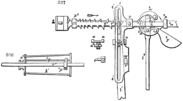
The manner in which this operates is shown in section in fig. 336. Here, we perceive the rod q2, which extends from the base towards the narrow end of the truncated cone, and p2 a forked bearer or carrier made fast to the shaft c′ by a screw, which compels the cone by means of that rod, to obey the movements of c′. In the large end of the cone there is an aperture, through which the bearer can be got at. The smaller end carries outside a projection o2, provided with a groove, which is embraced by the forked end of a rod q′, fig. 337., that serves to shove the cone along upon the shaft c′. Directly under the cone, there is an upright round pillar p′, upon which the holder o′ of the two guide pulleys l′ is adjustable. A bar r2 placed along-side of the holder, prevents its turning round, but allows it to slide along p′ by friction. The weight of the holder and the pulley is sufficient to distend the endless band n′, which runs from the cone k′, through under the pulley l′, and round the small drum m′ on the shaft s2. A pulley or whorl t2 with four grooves, is made fast by means of a tube to this shaft, and slides along it backwards and forwards, without ever ceasing to follow its revolutions. The shaft possesses for this purpose a long fork, and the interior of the tube a corresponding tongue or catch. There is besides upon the tube beneath the pulley, at u2, a groove that goes round it, in which the staple or forked end of an arm like v2, fig. 333., made fast to the copping beam p, catches. By the up and down movement of that beam, the pulley t2 takes along with it the arm that embraces the tube, which therefore rises and falls equally with the bobbins h′, and their pulleys or whorls q. This is requisite, since the bobbins are made to revolve by the pulleys t2, by means of 2 endless cords or bands.
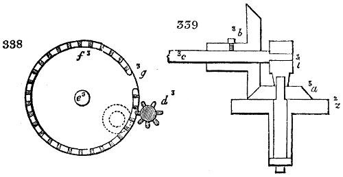
The most intricate part of the mechanism is the adjustment, by which the revolution of the bobbins is continually retarded, and their up and down, or copping motion, along the spindles, is also retarded in like proportion. The vertical pulley f′, (towards the left end of the shaft c′) has at its right side a somewhat larger disc or sheave g′, with a perfectly uniform, but not a very smooth surface. Upon this sheave, a smaller horizontal pulley x′ rubs, whose upper face is covered with leather to increase the friction. The under end of the shaft y2 of the pulley x′ turns in a step, which is so connected with the arm v′ of the large bent lever t′ v′, that it always stands horizontally, whatever direction the arms of that lever may assume. The shaft y2 is steadied at top by an annular holder or bush, which embraces the fast arm x2 with its forked end. Upon its opposite side, this arm carries a pulley y2, upon which a cord goes, that is made fast to the holder of the shaft y2, and loaded with the weight z′. The weight presses the pulley x′ against the surface of g′, in such wise as to effect the degree of friction necessary in order that the revolution of g′ may produce an uninterrupted revolution in x′. A pinion w′, whose length must be equal at least to the semi-diameter of the sheave g′, is placed upon the under end of the shaft y2. It has 22 teeth, and takes into a 62-toothed horizontal wheel z2. Upon the upper end of this wheel the conical pinion a3 is made fast, which may be changed for changing the speed, but usually has from 28 to 30 teeth. By this pinion the conical wheel b3 is turned, which has 30 teeth, and whose shaft is c3. This shaft carries upon its opposite end a six-leaved pinion, d3, which takes into the calender wheel f3, formed with cogs like a trundle, upon the long shaft e3. In fig. 338. the wheel f3 is exhibited with its pinion d3. Here we may remark that in the circumference of the wheel there is a vacant place, g3, void of teeth. When by the motion of the wheel, the pinion comes opposite to this opening, it turns round about the last tooth of the wheel, falls into the inside of the toothed circle marked by the dotted lines, and thus gives now an inverse movement to the wheel f3, while itself revolves always in the same direction. This reversed motion continues till the opening g3 comes once more opposite to the pinion, when this turns round about the last tooth of that side, and begins again to work in the exterior teeth. Thus, by the uniform motion of d3 and its dependent parts, the wheel f3, with its shaft e3, revolves alternately to the right hand and the left. That this result may ensue, the shaft c3 of the pinion must be able to slide endwise, without losing its hold of a3 and b3. This adjustment is effected by placing the end of the said shaft, nearest b3, in a box or holder i3, in which it can turn, and which forms a vertical tube to this box, as a downward prolongation which is fixed to the tail of the conical pinion a3. Fig. 339. shows this construction in section upon an enlarged scale. The second bearer of the shaft nearest d3, must possess likewise the means of lateral motion. When therefore the pinion d3 shifts through the opening of the wheel f3 outwards or inwards, its shaft c3, makes a corresponding small angular motion upon the pivot of a3, by means of the tube i3; a3 and b3 remain thereby completely in geer with one another.
The above-described alternate revolutions of the wheel f3 serve to produce the up and down motions of the bobbins. The shaft e3 has for this purpose two pinions n2 n2, which work in the rack teeth m2 m2 of the copping rail p, and thus alternately raise and sink it with the bobbins which rest upon it. The weight of the copping beam and all its dependent parts, is poised by two counterweights m4, whose cords run over the pulleys o4 o4 o4, fig. 332., and have their ends made fast to the frame, so as to make the upwards motion as easy as the downwards. The two upper pulleys out of the three of each weight, are fixed to the frame; the under one, round which the cord first runs, is attached to the copping beam, rising and falling along with it.
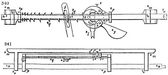
Figs. 340 and 341 enlarged (78 kB)
As long as the friction disc x′ remains at the same height, the pulley g′ derives its motion from the same circle of the said disc, and the up and down motion of the copping beam is also uniform. But when that disc ascends so as to describe with its edge a small circle upon the face of g′, its motion must become proportionally more slow. This is the method, or principle of retarding the copping motions of the bobbins. It has been shown, however, that the rotation of the bobbins should be also retarded in a progressive manner. This object is effected by means of the cone k′, which, as the band n′ progressively approaches towards its smaller diameter, drives the pulleys or whorls q of the bobbins with decreasing speed, though itself moves uniformly quick with the shaft c′. To effect this variation, the cone is shifted lengthwise along its shaft, while the band running upon it remains continually in the same vertical plane, and is kept distended by the weight of the pulley o′. The following mechanism serves to shift the cone, which may be best understood by the aid of the figures 340., 341., and 337. A long cast iron bar m3, which bears two horizontal projecting puppets, o3 o3, is made fast to the front upright face of the copping beam A. Through the above puppets a cylindrical rod n3 passes freely, which is left out in fig. 337., that the parts lying behind it may be better seen. Upon this rod there is a kind of fork, p3 p3, to which the alternating rack bars q3 are made fast. The teeth of these racks are at unequal distances from each other, and are so arranged, that each tooth of the under side corresponds to the space between two teeth in the upper side. Their number depends upon the number of coils of roving that may be required to fill a bobbin; and consists in the usual machines of from 20 to 22. The rod n3 may be shifted in the puppet o3, like the fork p3 of the rack-rod, upon the rod n3, and along the surface of m3, where two wings u3 u3 are placed, to keep the fork in a straight direction. Upon the bar m3, there are the pivots or fulcra of two stop catches w3 x3, of which the uppermost presses merely by its own weight, but the undermost by means of a counterweight y3, against the rack, and causes them thus to fall in between the teeth. In fig. 341., v3 shows the pivot of the catch or detent w3 by itself, the detent itself being omitted, to render the construction plainer. A pushing rod l3, upon which there is a pin above at s3, that passes behind the rack rod, between this and the bar m3, has for its object to remove at pleasure the one or the other of the two catches; the upper, when the upper end of the rod pushes against it; the under, by means of the above mentioned pin s3. Both the catches are never raised at once, but either the under or the upper holds the rack bar fast, by pressing against one of the teeth. The vertical motion up or down, which the rod l3 must take to effect the lifting of the catches, is given to it from the copping beam p; since upon it a horizontal arm v2, fig. 341., is fixed, that lays hold of that rod. Upon the pushing rod are two rings, h3 and k3, each made fast by a screw. When the copping beam is in the act of going up, the arm v3 at the end of this movement, pushes against the ring h3, raises up the rod l3, and thus removes the catch w3, fig. 337., from the teeth of the rod q3, before which it lies flat. At the descent of the copping rail, v2 meets the ring k3, when the motion in this direction is nearly completed, draws down the rod l3 a little, by means of the same, and thereby effects the removal of the catch x3, fig. 337., from the rod q3. Every time that one of the catches is lifted, the rack recovers its freedom to advance a little bit in the direction of the arrow; so far, namely, till the other catch lays hold upon the tooth that next meets it. The reason is thus manifest why the teeth of the upper and under sides of the bar q3 are not right opposite to each other, but in an alternate position.
From the rack-bar, the sliding of the cone k′, and the raising of the shaft y2, each by minute steps at a time, is produced as follows:—
A large rectangular lever t1, v1, whose centre of motion is at p4, has at the upper end of its long arm t1, a long slot through which a stud r3 upon the rack q3 goes (fig. 340., 341., 337.,) so that the lever must follow the motions of the rack bar. The end of the short arm of the lever bears, as already mentioned, the step of the shaft y2; hence the friction disc x1 will be raised in proportion as the rack bar advances, and will come nearer to the middle point of g1; consequently, its revolution and the shifting of the bobbins will become slower. Upon the cylindrical rod n3, the piece s1 s1 furnished with a long slot is made fast, by means of a tube z3, (fig. 337.) and a screw. A fork u u, which by means of the screw nut a4 is made fast in the slot, embraces the arm t1 of the bent lever; and a tube r1 rivetted to the surface of s1, is destined to take up the draw rod q1 of the cone k1, fig. 337. A weight f4, whose cord b4 is made fast to the cylindrical rod n3, endeavours to draw this rod continually in the direction of the arrow. In consequence of this arrangement, every time that the pushing bar l3 lifts up one of the catches, the cone k1, the lever t1 v1, and by it the rack bar q3, are set in motion. It is obvious, that the motion of the cone may be made greater or less, according as the fork u u is fixed further up or down in the slot of s1.
The number of the teeth upon the bar q3 is so ordered, that the bobbins are quite full when the last tooth has reached the catch and is released by it. The rack bar, being restrained by nothing, immediately slides onwards, in consequence of the traction of the weight f4 and brings the machine to repose by this very movement, for which purpose the following construction is employed. A rectangular lever which has its centre of motion in g4 is attached to the side face of the beam A, and has at the end of its horizontal arm a pulley d4, over which the cord b4 of the counterweight f4 is passed. The end of the perpendicular arm is forked and embraces the long and thin rod k4, to whose opposite end the fork l4 is made fast. Through this fork the band which puts the machine in motion passes down to the pulley a1. With the bent lever another rod c4 is connected at h4, which lies upon the puppet e3 with a slot at e4, and hereby keeps the lever g4 in its upright position notwithstanding the weight f4. In the moment when, as above stated, the rack bar q3 becomes free, the arm p3 of its fork pushes in its rapid advance against the under oblique side of e4, raises this rod, and thereby sets the lever g4 free, whose upright arm bends down by the traction of the weight, drives the rod k4 before it into the ring i4 fastened to it, and thus by means of the fork l4 shifts the band upon the loose pulley b1. But the machine may be brought to repose or put out of geer at any time merely by shifting the rod k4 with the hand.
The operation of the bobbin and fly frame may be fully understood from the preceding description. A few observations remain to be made upon the cone k1, the rack-bar q3, and the speed of the work.
When we know the diameter of the empty bobbins, and how many turns they should make in a given time in order to wind-on the sliver delivered by the fluted rollers and the spindles; when we consider the diameters of the spindle pullies q, and t2, as also the drum. m1, fig. 332., we may easily find the diameter which the cone must have for producing that number of turns. This is the diameter for the greatest periphery of the base. The diameter of the smaller is obtained in the same way, when the diameter of the bobbins before the last winding-on, as well as the number of turns necessary in a given time, are known.
A bobbin and fly frame of the construction just described delivers from each spindle in a day of twelve hours, from 6 to 8 lbs of roving of the fineness of 11⁄2 English counts. One person can superintend two frames, piece the broken slivers, and replace the full bobbins by empty ones. The loss of cotton wool in this machine consists in the portions carried off from the torn slivers, and must be returned to the lapping machine.
The fine bobbin and fly frame does not differ essentially from the preceding machine. The rovings from the coarse bobbin and fly frame are placed in their bobbins in a frame called the creel, behind and above the roller beam, two bobbins being allowed for one fluted portion of the rollers. These rovings are united into one, so as to increase the uniformity of the slivers.
The invention of the beautiful machine above described is due to Messrs. Cocker and Higgins of Manchester, and as lately improved by Henry Houldsworth, junr. Esq., it may be considered the most ingeniously combined apparatus in the whole range of productive industry.
In the fine roving frame the sliver is twisted in the contrary direction to that of the coarse roving frame. For this reason the position of the cone is reversed, so as to present in succession to the band or strap, diameters continually greater, in order that the rotation of the bobbins may be accelerated in proportion as their size is increased, because here the flyer and the bobbin turn in the same direction, and the winding-on is effected by the precession of the bobbin; but if the winding-on took place by its falling behind, as in the coarse bobbin and fly frame, that is, if the flyer turned less quickly than the bobbin, the rotatory speed of the bobbin would be uniformly retarded; in which case the cone would be disposed as in the coarse frame.
When by any means whatever an uniform length of thread is delivered by the rollers in a given time, the bobbin must wind it up as it is given out, and must therefore turn with a speed decreasing with the increase of its diameter by successive layers of thread. Hence proceeds the proposition, that the velocity of the bobbin must be in the inverse ratio of its diameter, as already explained.
With respect to the bobbin and fly frame, the twist is given to the sliver by means of a spindle or flyer which turns in the same direction with the bobbin, but quicker or slower than it, which establishes two predicaments. The first case is where the flyer turns faster than the bobbin. Here the winding-on goes in advance, as in the coarse roving frame, or as in throstle spinning, where the yarn is wound on merely in consequence of the friction of the lower disc or washer of the bobbin upon the copping rail, and of the drag of the yarn. The second case is where the flyer revolves more slowly than the bobbin. Here the winding goes on in arrear, and as the bobbin turns faster, it must receive a peculiar motion, which is uniformly retarded in the ratio of its increase of diameter. This is the case with the fine bobbin and fly frame. When the cone is placed as in fig. 332, the winding-on, in either the coarse or fine frame, results from the difference, whether greater or less, between the rotatory speed of the flyer and bobbin.
The motion of the bobbin and spindle is simultaneous, and takes place in the same direction, with a difference varying more or less with the varying diameters of the bobbins. To render the matter still clearer, suppose for a moment the spindle to be motionless, then the bobbin must revolve with such a speed, as to lap-on the roving as fast as the rollers deliver it. The sliver comes forward uniformly; but the bobbin, by its increase of diameter, must revolve with a speed progressively slower. Now, suppose the spindle set a-whirling, it is obvious that the bobbin must add to the movement requisite for winding-on the sliver, that of the spindle in the case of winding-on in arrear, or when it follows the flyers, and subtract its own motion from the twisting motion of the spindles, in the case of winding-on in advance, that is, when the bobbin precedes or turns faster than the flyers; for the diameter of the bobbin being 11⁄2 inch, 10 turns will take up 45 inches. Deducting these 10 turns from the 30 made by the spindle in the same time, there will remain for the effective movement of the bobbin only 20 turns; or when the diameter of the bobbin becomes 3 inches, 5 turns will take up the 45 inches, if the spindle be at rest; but if it makes 30 turns in the time, the effective velocity of the bobbin will be 25 turns, = 30 - 5. Hence in the fine bobbin and fly frame, the number of turns of the spindle, minus the number of turns made by the bobbin in equal times, is in the inverse ratio of the diameter of the bobbin. We thus perceive, that in the coarse frame the bobbin should move faster than the spindle, and that its speed should always diminish; whilst in the fine frame the bobbin should move slower than the spindle, but its speed should always increase. It is easy to conceive, therefore, why the cones are placed in reverse directions in the two machines. Not that this inversion is indispensably necessary; the cone of the fine roving frame might, in fact, be placed like that of the coarse roving frame; but as the torsion of the roving becomes now considerable, and as on that account the bobbin would need to move still faster, which would consume a greater quantity of the moving power, it has been deemed more economical to give its movement an opposite direction.
We mentioned that the twist of the sliver in the fine roving frame was the reverse of that in the coarse; this is a habit of the spinners, for which no good reason has been given.
The divisions of the rack-bar, and the successive diameters of the cone, must be nicely adjusted to each other. The first thing to determine is how much the rack should advance for every layer or range of roving applied to the bobbin, in order that the cone may occupy such a place that the strap which regulates the pulley barrel may be at the proper diameter, and thus fulfil every condition. The extent of this progressive movement of the rack depends upon the greater or less taper of the cone, and the increase which the diameter of the bobbin receives with every traverse, that is, every layer of roving laid on. But care should be taken not to taper the cone too rapidly, especially in the fine roving frame, because in its progress towards the smaller end, the strap would not slide with certainty and ease. We have already shown that the number of effective turns of the bobbin is inversely, as the diameter of the bobbin, or directly, as the successive diameters of the different points of the cone.
H. Houldsworth, jun. Esq. has introduced a capital improvement into the bobbin and fly frame, by his differential or equation-box mechanism, and by his spring fingers, which, by pressing the soft sliver upon the bobbin, cause at least a double quantity to be wound upon its barrel. With the description of his patent equation-box, I shall conclude the description of the bobbin and fly frame.
Fig. 342. represents a portion of a fly frame with Mr. Houldsworth’s invention. a a a are the front drawing rollers, turning upon bearings in the top of the machine, and worked by a train of toothed wheels, in the way that drawing rollers are usually actuated.
From the drawing rollers, the filaments of cotton or other material, b b, are brought down to, and passed through the arms of the flyers c c, mounted on the tops of the spindles d d, which spindles also carry the loose bobbins e e. In the ordinary mode of constructing such machines, the spindles are turned by cords or bands passing from a rotatory drum round their respective pulleys or whirls f, and the loose bobbins e, turn with them by the friction of their slight contact to the spindle, as before said; in the improved machine, however, the movements of the spindles and the bobbins are independent and distinct from each other, being actuated from different sources.
The main shaft of the engine g, turned by a band and rigger A as usual, communicates motion by a train of wheels h, through the shaft i, to the drawing rollers at the reverse end of the machine, and causes them to deliver the filaments to be twisted. Upon the main shaft g, is mounted a cylindrical hollow box or drum-pulley, whence one cord passes to drive the whirls and spindles f and d, and another to drive the bobbins e.
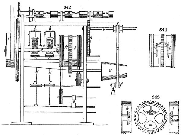
This cylindrical box pulley is made in two parts, k and l, and slipped upon the axle with a toothed wheel m, intervening between them. The box and wheel are shewn detached in fig. 343., and partly in section at fig. 344. That portion of the box with its pulley marked l, is fixed to the shaft g; but the other part of the box and its pulley k, and the toothed wheel m, slide loosely round upon the shaft g, and when brought in contact and confined by a fixed collar n, as in the machine shewn at fig. 342., they constitute two distinct pullies, one being intended to actuate the spindles, and the other the bobbins.
In the web of the wheel m, a small bevel pinion o, is mounted upon an axle standing at right angles to the shaft g, which pinion is intended to take into the two bevel pinions p and q, respectively fixed upon bosses, embracing the shaft in the interior of the boxes k and l. Now it being remembered that the pinion q, and its box l, are fixed to the shaft g, and turn with it, if the loose wheel m be independently turned upon the shaft, with a different velocity, its pinion o, taking into q, will be made to revolve upon its axle, and to drive the pinion p, and pulley box k, in the same direction as the wheel m; and this rotatory movement of the box k and wheel m, may be faster or slower than the shaft g, and box l, according to the velocity with which the wheel m is turned.
Having explained the construction of the box pullies k and l, which are the peculiar features of novelty claimed under this patent, their office and advantage will be seen by describing the general movements of the machine.
The main shaft g, being turned by the band and rigger A, as above said, the train of wheels h, connected with it, drives the shaft i, which at its reverse end has a pinion (not seen in the figure,) that actuates the whole series of drawing rollers a. Upon the shaft i there is a sliding pulley r, carrying a band s, which passes down to a tension pulley t, and is kept distended by a weight. This band s, in its descent, comes in contact with the surface of the cone u, and causes the cone to revolve by the friction of the band running against it. The pulley r is progressively slidden along the shaft i, by means of a rack and weight not shewn, but well understood as common in these kind of machines, and which movement of the pulley is for the purpose of progressively shifting the band s from the smaller to the larger diameter of the cone, in order that the speed of its rotation may gradually diminish as the bobbins fill by the winding-on of the yarns.
At the end of the axle of the cone u a small pinion v is fixed, which takes into the teeth of the loose wheel m, and, as the cone turns, drives the wheel m round upon the shaft g, with a speed dependent always upon the rapidity of the rotation of the cone. Now the box pulley l, being fixed to the main shaft g, turns with one uniform speed, and by cords passing from it over guides to the whorls f, drives all the spindles and flyers, which twist the yarns with one continued uniform velocity; but the box pulley k, being loose upon the shaft, and actuated by the bevel pinions within, as described, is made to revolve by the rotation of the wheel m, independent of the shaft, and with a different speed from the pulley box l; cords passing from this pulley box k, over guides to small pullies under the bobbins, communicate the motion, whatever it may be, of the pulley box k, to the bobbins, and cause them to turn, and to take up or wind the yarn with a speed derived from this source, independent of, and different from, the speed of the spindle and flyer which twist the yarn.
It will now be perceived, that these parts being all adjusted to accommodate the taking up movements to the twisting or spinning of any particular quality of yarn intended to be produced, any variations between the velocities of the spinning and taking up, which another quality of yarn may require, can easily be effected, by merely changing the pinion v, for one with a different number of teeth, which will cause the wheel m, and the pulley box k, to drive the bobbins faster or slower, as would be required in winding-on fine or coarse yarn, the speed of the twisting or spinning being the same.
The rovings or spongy cords, of greater or less tenuity, made on the bobbin and fly, or tube roving frame, are either spun immediately into firm cohesive yarn, or receive a further preparation process in the stretching frame, which is, in fact, merely a mule-jenny, without the second draught and second speed, and therefore need not be described at present, as it will be in its place afterwards.
The finishing machines of a cotton mill, which spin the cohesive yarn, are of two classes; 1. the water-twist or throstle, in which the twisting and winding are performed simultaneously upon progressive portions of the roving; and, 2. the mule, in which the thread is drawn out and stretched, with little twist, till a certain length of about 5 feet is extended, then the torsion is completed, and the finished thread is immediately wound upon the spindles into double conical coils called cops.
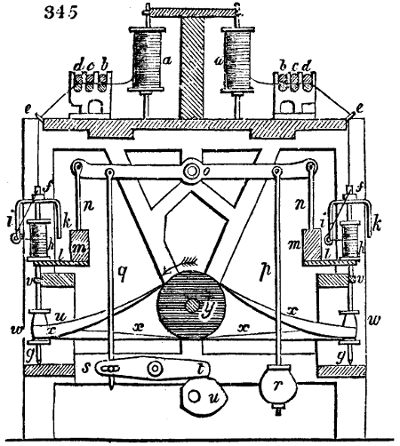
The water-twist frame, so called by its inventor, Sir R. Arkwright, because it was first driven by water, is now generally superseded by the throstle frame, in which the mechanical spinning fingers, so to speak, are essentially the same, but the mode of communicating the motion of the mill-geering to them is somewhat different. Fig. 345. exhibits a vertical section of the throstle. This machine is double, possessing upon each side of its frame, a row of spindles with all their subsidiary parts. The bobbins, filled with rovings from the bobbin and fly, or the tube frame, are set up in the creel a a, in two ranges, b, c, d, are the three usual pairs of drawing rollers, through which the yarn is attenuated to the proper degree of fineness, upon the principles already explained. At its escape from the front rollers, every thread runs through a guide eyelet e of wire, which gives it the vertical direction down towards the spindles f, g. The spindles which perform at once and uninterruptedly the twisting and winding-on of the thread delivered by the rollers, are usually made of steel, and tempered at their lower ends. They stand at g in steps, pass at v through a brass bush or collet which keeps them upright, and revolve with remarkable speed upon their axes. The bobbins h, destined to take up the yarn as it is spun, are stuck loosely upon the spindles, and rest independently of the rotation of the spindles upon the copping beam l, with a leather washer between. Upon the top of the spindles an iron-wire fork, called a fly or flyer, i, k, is made fast by a left-hand screw, and has one of its forks turned round at the end into a little ring. The branch of the flyer at f is tubular, to allow the thread to pass through, and to escape by a little hole at its side, in order to reach the eyelet at the end of that fork. From this eyelet i, it proceeds directly to the bobbin. By the twirling of the spindle, the twisting of the portion of thread between the front roller d, and the nozzle f, is effected. The winding-on takes place in the following way:—Since the bobbin has no other connection with the spindle than that of the thread, it would but for it remain entirely motionless, relatively to the spindle. But the bobbin is pulled after it by the thread, so that it must follow the rotation of the spindle and fly. When we consider that the thread is pinched by the front roller d, and is thereby kept fully upon the stretch, we perceive that the rotation of the bobbin must be the result. Suppose now the tension to be suspended for an instant, while the rollers d, deliver, for example, one inch of yarn. The inertia or weight of the bobbin, and its friction upon the copping beam l, by means of the leather washer, will, under this circumstance, cause the bobbin to hang back in a state of rest, till the said inch of yarn be wound on by the whirling of the fly i, and the former tension be restored. The delivery of the yarn by the drawing rollers, however, does not take place inch after inch, by starts, but at a certain continuous rate; whence results a continuous retardation or loitering, so to speak, of the bobbins behind the spindles, just to such an amount that the delivered yarn is wound up at the same time during the rotation.
This process in spinning is essentially the same as what occurs in the fine bobbin and fly frame, but is here simplified, as the retardation regulates itself according to the diameter of the bobbin by the drag of the thread. In the fly frame the employment of this tension is impossible, because the roving has too little cohesion to bear the strain; and hence it is necessary to give the bobbins that independent movement of rotation which so complicates this machine.
The up and down motion of the bobbins along the spindles, which is required for the equal distribution of the yarn, and must have the same range as the length of the bobbin barrels, is performed by the following mechanism. Every copping rail l, is made fast to a bar m, and this, which slides in a vertical groove or slot at the end of the frame, is connected by a rod n, with an equal-armed, moveable lever o. The rod p carries a weight r, suspended from this lever; another rod q, connects the great lever o with a smaller one s, t, upon which a heart-shaped disc or pulley u, works from below at t. By the rotation of the disc u, the arm t, being pressed constantly down upon it by the reaction, the weight r must alternately rise and fall; and thus the copping rail l must obviously move with the bobbins h up and down; the bobbins upon one side of the frame rising, as those upon the other sink. Strictly considered, this copping motion should become slower as the winding-on proceeds, as in the fly roving frame; but, on account of the smallness of the finished thread, this construction, which would render the machine complicated, is without inconvenience neglected, with the result merely that the coils of the yarn are successively more sparsely laid on, as the diameter of the bobbin increases.
The movement of the whole machine proceeds from the shaft of a horizontal drum, which drives the spindles by means of the endless bands x x. Each spindle is mounted with a small pulley or wharf w, at its lower part, and a particular band, which goes round that wharf or whorl, and the drum y. The bands are not drawn tense, but hang down in a somewhat slanting direction, being kept distended only by their own weight. Thus every spindle, when its thread breaks, can readily be stopt alone, by applying a slight pressure with the hand or knee, the band meanwhile gliding loosely round the whorl.
The velocities of rotation of the three drawing rollers are, according to this arrangement, in the proportion of 1 : 11⁄2 : 8; and as their diameters are the same, namely, one inch, the elongation of the yarn in spinning is eight-fold. If, for example, the roving was of the number 41⁄2, the yarn would become No. 36. The extension of the thread may be changed by changing the wheels of the drawing rollers. To perceive the power of this change, let us put, for example, in the place of the 18-toothed wheel of the back rollers, a wheel with 16 teeth; we shall find that the elongation will amount, in that case, only to 71⁄2 times, whence the number of the yarn would come out 32 = 71⁄2 × 41⁄2. The extension by the throstle is extremely various; it amounts, in some cases, to only 4 times; at others to 10, 12, or even 15.
The copping motion of the bobbins is produced in consequence of a bevel pinion working in a small bevel wheel upon an upright shaft; while this wheel gives a slow motion by means of a worm screw to the wheel of the heart-shaped pulley u, fig. 345.
The driving pulley makes about 600 turns in a minute; and as the diameter of the drum y, fig. 345., is six times the diameter of the spindle wharves w, it will give 3600 turns to the spindle in that time. If the pulley be driven faster, for example 700 times in a minute, it will increase the revolutions of the spindles to 4200. The degree of twist which will be thereby imparted to the yarn, depends, with like speed of spindles, upon the rate at which the soft yarn is delivered by the drawing rollers; for the quicker this delivery, the quicker is the winding-on, and the less twist goes into a given length of yarn. If, for example, the front rollers d, turn 24 times in a minute, giving out of course 72 inches of yarn in this time, upon which the 3600 revolutions of the spindle are expended, there will be 50 twists to every inch of yarn. By changing the wheel-work of fig. 345., or by sticking greater or smaller wharves upon the spindles, the proportion between their velocity and that of the drawing rollers, and thence the degree of twist can be modified at pleasure.
The number of spindles in a throstle frame 12 feet long, is about 60 on each side. The drawing rollers are coupled together as in the bobbin and fly frame, so that each row forms one continuous cylinder. There is a complete roller beam on each side; each of the rollers of the front row is pressed by its top rollers with a weight of ten or twelve pounds; but those of the middle and back rows bear weights of only one pound. In the throstles, there is a guide bar which traverses a small way horizontally to the left and right, in front of the roller beam, to lead the thread along different points of the rollers, and thus prevent the leather of the top ones from being grooved by its constant pressure in one line.
For the service of 240 spindles, in two double frames, one young woman, and an assistant piecer are sufficient. They mend the broken ends, and replace the empty bobbins in the creel with full ones, and the full bobbins of the throstle by empty ones. The average quantity of yarn turned off in a week of 69 hours is about 24 hanks per spindle of 30′s twist. Throstle yarn is of a firm wiry quality, adapted to the warps of fustians and other strong stuffs, as well as to the manufacture of stockings and sewing thread.
There are many modifications of the throstle system besides the one above described; the most celebrated of which are Danforth’s, called the American throstle, Montgomery’s, and Gore’s. I must refer for an account of them to my work entitled “The Cotton Manufacture of Great Britain,” where they are minutely described and illustrated with accurate figures.
Mule-spinning.—The general principles of the mule have been already stated. This machine is so named because it is the offspring, so to speak, of two older machines, the jenny and the water-frame. A mule is mounted with from 240 to 1000 spindles, and spins of course as many threads.
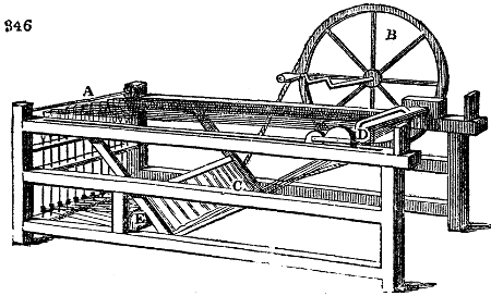
Fig. 346. represents the original jenny of Hargreaves, by which one person was enabled to spin from 16 to 40 threads at once. The soft cords of rovings wound in double conical cops upon skewers were placed in the inclined frame at C; the spindles for first twisting and then winding-on the spun yarn were set upright in steps and bushes at A, being furnished near their lower ends with whorls, and endless cords, which were driven by passing round the long-revolving drum of tin plate E. D is the clasp or clove, having a handle for lifting its upper jaw a little way, in order to allow a few inches of the soft roving to be introduced. The compound clove D being now pushed forward upon its friction wheels to A, was next gradually drawn backward, while the spindles were made to revolve with proper speed by the right hand of the operative turning the flywheel B. Whenever one stretch was thereby spun, the clove frame was slid home towards A; the spindles being simultaneously whirled slowly to take up the yarn, which was laid on in a conical cop by the due depression of the faller wire at A with the spinner’s left hand.
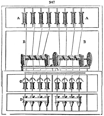
Fig. 347. is a diagram of Arkwright’s original water-frame spinning machine, called afterwards the water-twist frame. The rovings mounted upon bobbins in the creel A A, have their ends led through between the three sets of twin rollers below B B, thence down through the eyelet hooks upon the end of the flyers of the spindles C, and finally attached to their bobbins. The spindles being driven by the band D D upon their lower part, continuously twist and wind the finished yarn upon the bobbins; constituting the first unremitting automatic machine for spinning which the world ever saw.
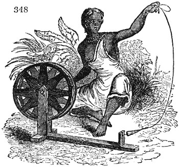
Contrast with the above admirable system, the primitive cotton wheel of India, as represented in the annexed figure 348. By the aid of mechanical fingers, one Englishman at his mule can turn off daily more yarn and of far finer quality than 200 of the most diligent spinsters of Hindostan.
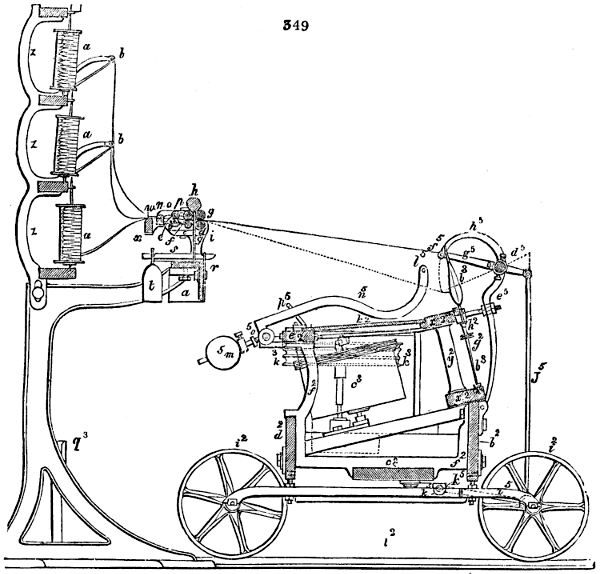
Fig. 349 enlarged (195 kB)
Fig. 349., is a transverse section of the mule, in which its principal parts are shown.
The machine consists of two main parts; a fixed one corresponding in some measure to the water-frame or throstle, and a moveable one corresponding to the jenny. The first contains in a suitable frame the drawing roller-beam and the chief moving machinery: the second, is called the carriage, in which the remainder of the moving mechanism and the spindles are mounted.
The frame of the fixed part consists of two upright sides, and two or more intermediate parallel bearings, upon which the horizontal roller beam a, the basis of the drawing rollers is supported, b, c, d, are the three ranges of fluted iron rollers; e, f, g, are the upper iron rollers covered with leather; h, the wooden wiper-rollers covered with flannel, which being occasionally rubbed with chalk, imparts some of it to the pressure rollers beneath, so as to prevent the cotton filaments adhering to them. The rollers are made throughout the whole length of the mule in portions containing six flutings, which are coupled together by squared ends fitted into square holes.
The skewers upon which the bobbins containing the rovings from the bobbin and fly or stretching frame, are set up, are seen at a1, a1, a1, arranged in three rows in the creel z. The soft threads unwound from these bobbins, in their way to the drawing rollers, pass first through eyelets in the ends of the wire arms b1, then through the rings or eyes of the guide bar w, and enter between the back pair of rollers. The number of these bobbins is equal to the number of spindles in the mule, and twice as great as the number of fluted portions of the rollers; for two threads are assigned to each portion.
The carriage consists of two cast-iron side pieces, and several cast-iron intermediate similar pieces, such as f2, which all together are made fast to the planks b2, c2, d2. The top is covered in with the plank k2. The carriage runs by means of its cast-iron grooved wheels, upon the cast-iron railway l2, which is fixed level on the floor.
The spindles stand upon the carriage in a frame, which consists of two slant rails x2, x2, connected by two slender rods y2, and which frame may be set more or less obliquely. The lower rail carries the brass steps for the points of the spindles b3; upon the upper rail brass slips are fixed pierced with holes through which the tops of the spindles play. The spindles are as usual made of steel, perfectly straight, turned truly round, and are all arranged in one plane. To each of them a small wooden or cast-iron whorl g2 is made fast. They are distributed into groups of 24, and the whorls are arranged at such different heights, that only two of them in each group are upon a level with each other. A small brass head h2, which every spindle has beneath the upper slant rail of the frame x2, prevents their sitting down into the step, during their rotation, or sliding off their cop of yarn.
c3 are drums, mounted in the carriage in a plane at right angles to the plane in which the spindles are placed. At top they have a double groove for a cord to run in, and the motion which they receive from the great fly wheel, or rim of the mule (not visible in this view) they impart to the spindles. Such a drum is assigned to every 24 spindles; and therefore a mule of 480 spindles contains 20 drums. In the middle of the carriage is seen the horizontal pulley k3, furnished with three grooves, which stands in a line with the drums c3.
The motion is given to the drums c3, upon the right hand half of the carriage by a single endless band or cord which proceeds from the middle groove of the pulley k3. The rotation of the spindles is produced by a slender cord, of which there are 12 upon each drum c3; because every such cord goes round the drum, and also every two wharves which stand at the same level upon the spindles. It is obvious that the drums, and consequently the spindles, must continue to revolve as long as the main rim of the mule is turned, whether the carriage be at rest or in motion upon its railway.
If we suppose the carriage to be run in to its standing point, or to be pushed home to the spot from which it starts in spinning, its back plank d2 will strike the post q3 upon the fixed frame, and the points of the spindles will be close in front of the roller beam. The rollers now begin to turn and to deliver threads, which receive immediately a portion of their twist from the spindles; the carriage retires from the roller beam with somewhat greater speed than the surface speed of the front rollers, whereby the threads receive a certain degree of stretching, which affects most their thicker and less twisted portions, and thereby contributes greatly to the levelness of the yarn. When the carriage has run out to the end of its course, or has completed a stretch, the fluted rollers suddenly cease to revolve (and sometimes even beforehand, when a second stretch is to be made), but the spindles continue to whirl till the fully extended threads have received the proper seconder after-twist. Then the carriage must be put up, or run back towards the rollers, and the threads must be wound upon the spindles.
This is the order of movements which belong to the mule. It has been shown how the rotation of the spindles is produced.
For winding-on the yarn the carriage has a peculiar apparatus, which we shall now describe. In front of it, through the whole extent to the right hand as well as the left, a slender iron rod, d5, runs horizontally along, in a line somewhat higher than the middle of the copping portion of the spindles, and is supported by several props, such as e5. Upon each end of the two rods, d5, there is an arm, g5; and betwixt these arms an iron wire, called the copping wire, f5, is stretched, parallel with the rod d5. For the support of this wire, there are several slender bent arms h5 extended from the rod d5 at several points betwixt the straight arms g5. The rod d5 has, besides a wooden handle at the place opposite to where the spinner stands, by which it can be readily grasped. This movement is applied at the left division of the machine, and it is communicated to the right by an apparatus which resembles a crane’s bill. The two arms, g5, in the middle of the machine, project over the rods d5, and are connected by hinges with two vertical rods j5, which hang together downwards in like manner with two arms i5, proceeding from a horizontal axis k5.
By means of that apparatus the yarn is wound upon the spindles in the following manner. As long as the stretching and twisting go on, the threads form an obtuse angle with the spindles, and thereby slide continually over their smooth rounded tips during their revolution, without the possibility of coiling upon them. When, however, the spinning process is completed, the spinner seizes the carriage with his left hand and pushes it back towards the roller beam, while with his right hand he turns round the handle of the rim or fly wheel, and consequently the spindles. At the same time, by means of the handle upon the rod d5, he moves the copping-wire, f5, so that it presses down all the threads at once, and places them in a direction nearly perpendicular to the spindles; as shown by the dotted line y5. That this movement of the copping wire, however, may take place without injury to the yarn, it is necessary to turn the rim beforehand a little in the opposite direction, so that the threads may get uncoiled from the upper part of the spindles, and become slack; an operation called in technical language, the backing off. The range upon which the threads should be wound, in order to form a conical cop upon the spindle, is hit by depressing the copping wire to various angles, nicely graduated by an experienced eye. This faller wire alone is not, however, sufficient for the purpose of winding-on a seemly cop, as there are always some loose threads which it cannot reach without breaking others.
Another wire called the counter-faller, l5, must be applied under the threads. It may be raised to an elevation limited by the angular piece p5; and is counterpoised by a very light weight m5, applied through the bent lever n5, which turns upon the fulcrum o5. This wire, which applies but a gentle pressure, gives tension to all the threads, and brings them regularly into the height and range of the faller f5. This wire must be raised once more, whenever the carriage approaches the roller beam. At this instant a new stretch commences; the rollers begin again to revolve, and the carriage resumes its former course. These motions are performed by the automatic machinery.
There is a little eccentric pulley mechanism for moving the guide beam to and fro with the soft yarns, as they enter between the back rollers. On the right hand end of the back roller shaft, a worm screw is formed which works into the oblique teeth of a pinion attached to the end of the guide beam, in which there is a series of holes for the passage of the threads, two threads being assigned to each fluted roller. In the flat disc of the pinion, an eccentric pin stands up which takes into the jointed lever upon the end of the guide beam, and as it revolves, pushes that beam alternately to the left and the right by a space equal to its eccentricity. This motion is exceedingly slow, since for each revolution of the back roller, the pinion advances only by one tooth out of the 33 which are cut in its circumference.
After counting the number of teeth in the different wheels and pinions of the mule, or measuring their relative diameters, it is easy to compute the extension and twist of the yarns; and when the last fineness is given to ascertain their marketable value. Let the ratio of speed between the three drawing rollers be 1 : 13⁄22 : 71⁄2; and the diameter of the back and middle roller three quarters of an inch: that of the front roller one inch; in which case the drawing is thereby increased 11⁄3 times, and 71⁄2 × 11⁄3 = 10. If the rovings in the creel bobbins have been No. 4. the yarn, after passing through the rollers, will be No. 40. By altering the change pinion (not visible in this view) the fineness may be changed within certain limits, by altering the relative speed of the rollers. For one revolution of the great rim or fly wheel of the mule, the front roller makes about 6-tenths of a turn, and delivers therefore 22·6 lines or 12ths of an inch of yarn, which, in consequence of the tenfold draught through the rollers, corresponds to 2·26 lines of roving fed in at the back rollers. The spindles or their whorls make about 66 revolutions for one turn of the rim. The pulleys or grooved wheels on which the carriage runs, perform 0·107 part of a turn while the rim makes one revolution, and move the carriage 24·1 lines upon its rails, the wheels being 6 inches in diameter.
The 22·6 lines of soft yarn delivered by the front rollers, will be stretched 11⁄2 lines by the carriage advancing 24·1 lines in the same time. Let the length of the railway, or of each stretch be 5 feet, the carriage will complete its course after 30 revolutions of the rim wheel, and the 5 feet length of yarn (of which 561⁄2 inches issue from the drawing rollers, and 31⁄2 inches proceed from the stretching) is, by the simultaneous whirling of the spindles, twisted 1980 times, being at the rate of 33 twists for every inch. The second twist, which the threads receive after the carriage has come to repose, is regulated according to the quality of the cotton wool, and the purpose for which the yarn is spun. For warp yarn of No. 40 or 50, for example, 6 or 8 turns of the rim wheel, that is, from 396 to 528 whirls of the spindles for the whole stretch, therefore from 7 to 9 twists per inch will be sufficient. The finished yarn thus receives from 40 to 42 twists per inch.
One spinner attends to two mules, which face each other, so that he needs merely turn round in the spot where he stands, to find himself in the proper position for the other mule. For this reason the rim wheel and handle, by which he operates, are not placed in the middle of the length of the machine, but about two fifths of the spindles are to the right hand and three fifths to the left; the rim wheel being towards his right hand. The carriage of the one mule is in the act of going out and spinning, while that of the other is finishing its twist, and being put up by the spinner.
The quantity of yarn manufactured by a mule in a given time, depends directly upon the number of the spindles, and upon the time taken to complete every stretch of the carriage. Many circumstances have an indirect influence upon that quantity, and particularly the degree of skill possessed by the spinner. The better the machine, the steadier and softer all its parts revolve, the better and more abundant is its production. When the toothed wheels do not work truly into their pinions, when the spindles shake in their bushes, or are not accurately made, many threads break, and the work is much injured and retarded. The better the staple of the cotton wool, and the more careful has been its preparation in the carding, drawing, and roving processes, the more easy and excellent the spinning will become: warmth, dryness, cold, and moisture have great influence on the ductility, so to speak, of cotton. A temperature of 65° F., with an atmosphere not too arid, is found most suitable to the operations of a spinning mill. The finer the yarn, the slower is the spinning. For numbers from 20 to 36, from 2 to 3 stretches of warp may be made in a minute, and nearly 3 stretches of weft; for numbers above 50 up to 100, about 2 stretches; and for numbers from 100 to 150, one stretch in the minute. Still finer yarns are spun more slowly, which is not wonderful, since in the fine spinning mills of England, the mules usually contain upwards of 500 spindles each, in order that one operative may manage a great number of them, and thereby earn such high wages as shall fully remunerate his assiduity and skill.
In spinning fine numbers, the second speed is given before the carriage is run out to the end of its railway; during which course of about six inches, it is made to move very slowly. This is called the second stretch, and is of use in making the yarn level by drawing down the thicker parts of it, which take on the twist less readily than the thinner, and therefore remain softer and more extensible. The stretch may therefore be divided into three stages. The carriage first moves steadily out for about 4 feet, while the drawing rollers and spindles are in full play; now the rollers stop, but the spindles go on whirling with accelerated speed, and the carriage advances slowly, about 6 inches more; then it also comes to rest, while the spindles continue to revolve for a little longer, to give the final degree of twist. The acceleration of the spindles in the second and third stages, which has no other object but to save time, is effected by a mechanism called the counter, which shifts the driving band, at the proper time, upon the loose pulley, and, moreover, a second band, which had, till now, lain upon its loose pulley, upon a small driving pulley of the rim-shaft. At length, both bands are shifted upon their loose pulleys, and the mule comes to a state of quiescence.
The SELF-ACTOR MULE, or the IRON MAN, as it has been called in Lancashire, is an invention to which the combinations among the operative spinners obliged the masters to have recourse. It now spins good yarn up to 40 s with great uniformity and promptitude, and requires only juvenile hands to conduct it, to piece the broken yarns, to replace the bobbins of rovings in the creel, and to remove the finished cops from the spindles.
The self-acting mules were first constructed, I believe, by Messrs. Eaton, formerly of Manchester, who mounted ten or twelve of them in that town, four at Wiln, in Derbyshire, and a few in France. From their great complexity and small productiveness, the whole were soon relinquished, except those at Wiln. M. de Jong obtained two patents for self-acting mules, and put twelve of them in operation in a mill at Warrington, of which he was part proprietor; but with an unsuccessful result. I saw the débris of one of M. de Jong’s self-actors in the factory of M. Nicolas Schlumberger, at Guebwiller, in Alsace, where the machine had been worked for three months, without advantage, under the care of the inventor, who is a native of that valley.
The first approximation to a successful accomplishment of the objects in view, was an invention of a self-acting mule, by Mr. Roberts, of Manchester; one of the principal points of which was the mode of governing the winding-on of the yarn into the form of a cop; the entire novelty and great ingenuity of which invention was universally admitted, and proved the main step to the final accomplishment of what had so long been a desideratum. For that invention a patent was obtained in 1825, and several headstocks upon the principle were made, which are still working successfully.
In 1830, Mr. Roberts obtained a patent for the invention of certain improvements; and by a combination of both his inventions, he produced a self-acting mule, which is generally admitted to have exceeded the most sanguine expectations, and which has been extensively adopted. There are, probably, at present, upwards of half a million of spindles of Messrs. Sharp, Roberts, and Co.’s construction, at work in the United Kingdom, and giving great satisfaction to their possessors. The advantages of these self-actors are the following:—
The saving of a spinner’s wages to each pair of mules, piecers only being required, as one overlooker is sufficient to manage six or eight pairs of mules. The production of a greater quantity of yarn, in the ratio of from 15 to 20 per cent. The yarn possesses a more uniform degree of twist, and is not liable to be strained during the spinning, or in winding-on, to form the cop; consequently fewer threads are broken in these processes, and the yarn, from having fewer piecings is more regular.
The cops are made firmer, of better shape, and with undeviating uniformity; and, from being more regularly and firmly wound, contain from one third to one half more yarn than cops of equal bulk wound by hand; they are consequently less liable to injury in packing or in carriage, and the expense of packages and freight (when charged by measurement) is considerably reduced.
From the cops being more regularly and firmly wound, combined with their superior formation, the yarn intended for warps less frequently breaks in winding or reeling, consequently there is a considerable saving of waste in those processes.
Secondly, the advantages connected with weaving.
The cops being more regularly and firmly wound, the yarn, when used as weft, seldom breaks in weaving; and as the cops also contain a greater quantity of weft, there are fewer bottoms, consequently there is a very material saving of waste in the process of weaving.
From those combined circumstances, the quality of the cloth is improved, by being more free from defects caused by the breakage of the warp or weft, as well as the selvages being more regular.
The looms can also be worked at greater speed; and, from there being fewer stoppages, a greater quantity of cloth may be produced.
That the advantages thus enumerated, as derivable from the use of self-acting mules, have not been overrated, but, in many instances, have been considerably exceeded, I have, by extensive personal inquiry and observation, had ample opportunity of ascertaining.
Statement of the quantity of yarn produced on Messrs. Sharp, Roberts, and Co.’s self-acting mules, in twelve working hours, including the usual stoppages connected with spinning, estimated on the average of upwards of twenty mills:—
No. of Yarn. No. of Twist. No. of Weft.
16 4 1⁄2 hanks 4 7⁄8 hanks per spindle.
24 4 1⁄4 — 4 5⁄8 —
32 4 — 4 3⁄8 —
40 3 3⁄4 — 4 1⁄8 —
Of the intermediate numbers the quantities are proportionate.
Results of trials made by Messrs. Sharp, Roberts, and Co., at various mills, to ascertain the comparative power required to work self-acting mules, in reference to hand-mules, during the spinning, up to the period of backing off.
Particulars of the trials referred to, and their results:—
At what Mill, and the Description of Mule. No. and kind of Yarn. Diameter of Pulley or Rim Wheel. Revo- lutions of Pulley or Rim Wheel. Re- quired Force for Motion. Total Force Employed in Spinning.
Messrs. Birley and Kirk. Weft. Ins. lbs. lbs.
Self-acting mule, 360 sps. 30 to 34 12 58 30 5463
[20]Hand mule, 180 sps. ditto 15 36 26 3669 -
× 2 = 7338
Messrs. Leech and Vandrey. Twist.
[21]Self-acting mule, 324 sps. 36 12 70 36 7912
Hand mules, 324 sps. 36 29 58 16 1⁄2 7273
Messrs. Duckworth & Co. Twist.
Self-acting mule, 324 sps. 40 12 62 33 6421
Hand mule, 324 sps. 40 47 36 15 1⁄2 6646
The mode adopted to make the trials was as follows, viz.:
A force, indicated by weight in pounds, was applied to the strap working upon the driving-pulley of the respective mules, sufficient to maintain the motion of the mule whilst spinning, which weight, being multiplied by the length of strap delivered by each revolution of the pulley, and again by the number of revolutions made by the pulley whilst spinning, gave the total force in pounds, applied to the respective mules whilst spinning; for instance, suppose a mule to be driven by a pulley 12 inches diameter (3·14 ft. in circumference), such pulley making 58 revolutions during the spinning as above, and that it required a force equal to 30 lbs. weight to maintain the motion of the mule, then 30 lbs. × 3·14 feet circumference of pulley × 58 revolutions in spinning = 5463 lbs. of force employed during the spinning, to the period of backing off.
Mr. James Smith, of Deanstone cotton works in Scotland, obtained a patent for the invention of a self-actor, in February, 1834. He does not perform the backing-off by reversing the rotation of the spindle, as in common mules, or as in Mr. Roberts’, but by elevating the counterfaller wire, which, being below the ends of the yarn or thread, along the whole extent of the carriage, thereby pulls off or strips the spiral coils at the point of the spindle, instead of unwinding them, as of old. This movement he considers to be of great importance towards simplifying the machinery for rendering the mule self-acting; and the particular way in which he brings the stripper into action is no doubt ingenious, but it has been supposed by many to strain the yarn. He claims as his invention the application and adaptation of a mangle wheel or mangle rack to the mule, for effecting certain successive movements, either separately or in conjunction; he claims that arrangement of the carriages of a pair of mules, by which the stretch is caused to take place over part of the same ground by both carriages, and thereby the space required for the working of a pair of mules is greatly diminished; and he claims the application of a weight, spring, or friction, for balancing the tension of the ends of the threads.
A patent was granted, in April, 1835, to Mr. Joseph Whitworth, engineer in Manchester, for some ingenious modifications of the mechanism of the mule, subservient to automatic purposes. His machinery is designed, first, to traverse the carriage in and out, by means of screws or worm-shafts, which are placed so as to keep the carriage parallel to the drawing rollers, and prevent the necessity of squaring bands, hitherto universally employed; secondly, his invention consists in an improved manner of working the drums of a self-acting mule by geer; thirdly, in the means of effecting the backing off; fourthly, in the mechanism for working the faller-wire in building the cops; and fifthly, in the apparatus for effecting the winding of the yarns upon the spindles. As regards the throstles and doubling frames, his improvements apply, first, to the peculiar method of constructing and adapting the flyers and spindles, and producing the drag; and, secondly, to the arrangement of the other parts of the doubling machinery.
See Lace-Making, Singeing, Textile Fabric, Thread Manufacture, and Weaving.
The Imports of Cotton Wool for home consumption into the United Kingdom were in the year ending 5th January,
1836. 1837.
lbs. lbs.
From the British possessions in America 1,346,220 1,041,434
Fro—the Bdo.h possedo.ns in>East Indies 43,404,058 34,060,055
Fro—the United States of America 287,346,721 309,027,306
Fro—the Brazil 26,879,779 20,822,509
Fro—the Egypt 5,184,743 7,465,774
Otherwise imported 6,789,603 5,602,602
Total 370,951,124 378,019,680
£ £
The Exports of Cotton Manufactures 18,511,692 13,625,464
The export—of CottonYarn 6,120,366 6,953,467
COURT PLASTER, is a considerable object of manufacture. It is made as follows:
Black silk is strained and brushed over ten or twelve times with the following preparation:—Dissolve 1⁄2 an ounce of balsam of benzoin in 6 ounces of rectified spirits of wine; and in a separate vessel dissolve 1 ounce of isinglass in as little water as may be. Strain each solution, mix them, and let the mixture rest, so that any undissolved parts may subside; when the clear liquid is cold it will form a jelly, which must be warmed before it is applied to the silk. When the silk coated with it is quite dry, it must be finished off with a coat of a solution of 4 ounces of China turpentine in 6 ounces of tincture of benzoin, to prevent its cracking.[22]
CRAPE. (Crêpe, Fr.; Krepp, Germ.) A transparent textile fabric, somewhat like gauze, made of raw silk, gummed and twisted at the mill. It is woven with any crossing or tweel. When dyed black, it is much worn by ladies as a mourning dress. Crapes are crisped (crepés) or smooth; the former being double, are used in close mourning, the latter in less deep. White crape is appropriate to young unmarried females, and to virgins on taking the veil in nunneries. The silk destined for the first is spun harder than for the second; since the degree of twist, particularly of the warp, determines the degree of crisping which it assumes after being taken from the loom. It is for this purpose steeped in clear water, and rubbed with prepared wax. Crapes are all woven and dyed with the silk in the raw state. They are finished with a stiffening of gum water.
Crape is a Bolognese invention, but has been long manufactured with superior excellence at Lyons in France, and Norwich in England. There is now a magnificent fabric of it at Yarmouth, by power-loom machinery.
There is another kind of stuff, called crepon, made either of fine wool, or of wool and silk, of which the warp is twisted much harder than the weft. The crepons of Naples consist altogether of silk.
CRAYONS. (Eng. and Fr.; Pastelstifte, Germ.) Slender, soft, and somewhat friable cylinders, variously coloured for delineating figures upon paper, usually called chalk drawings. Red, green, brown, and other coloured crayons, are made with fine pipe or china clay paste, intimately mixed with earthy or metallic pigments, or in general with body or surface colours, then moulded and dried. The brothers Joel, in Paris, employ as crayon cement the following composition: 6 parts of shell-lac, 4 parts of spirit of wine, 2 parts of turpentine, 12 parts of a colouring powder, such as Prussian-blue, orpiment, whitelead, vermillion, &c., and 12 parts of blue clay. The clay being elutriated, passed through a hair sieve, and dried, is to be well incorporated by trituration with the solution of the shell-lac in the spirit of wine, the turpentine, and the pigment; and the doughy mass is to be pressed in proper moulds, so as to acquire the desired shape. They are then dried by a stove heat.
In order to make cylindrical crayons, a copper cylinder is employed, about 2 inches in diameter, and 11⁄2 inches long, open at one end, and closed at the other with a perforated plate, containing holes corresponding to the sizes of the crayons. The paste is introduced into the open end, and forced through the holes of the bottom by a piston moved by a strong press. The vermicular pieces that pass through are cut to the proper lengths, and dried. As the quality of the crayons depends entirely upon the fineness of the paste, mechanical means must be resorted to for effecting this object in the best manner. The following machine has been found to answer the purpose exceedingly well.
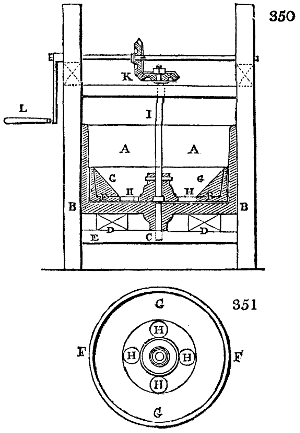
Fig. 350. is a vertical section through the centre of the crayon mill. Fig. 351. is a view of the mill from above. A, the mill tub, whose bottom B must be a hard flat plate of cast iron; the sides A being of wood or iron at pleasure. In the centre of the bottom there is a pivot C, screwed into a socket cast upon the bottom, and which may be strengthened by two cross bars D, made fast to the frame E. F, the millstone of cast-iron, concave, whose diameter is considerably smaller than that of the vessel A; it is furnished within with a circular basin of wood G, which receives the materials to be ground, and directs them to the holes H, which allow them to pass down between the under part of the muller, and the bottom of the tub, to undergo trituration.
By the centrifugal motion, the paste is driven towards the sides of the vessel, rises over the sides of the muller, and comes again through the holes H, so as to be repeatedly subjected to the grinding operation. This millstone is mounted upon an upright shaft I, which receives rotatory motion from the bevel wheel work K, driven by the winch L.
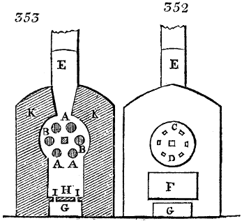
The furnace in which some kinds of crayons, and especially the factitious blacklead pencils are baked, is represented in fig. 352. in a front elevation; and in fig. 353., which is a vertical section through the middle of the chimney.
A A, six tubes of greater or less size, according as the substance of the crayons is a better or worse conductor of heat. These tubes, into which the crayons intended for baking are to be put, traverse horizontally the laboratory B of the furnace, and are supported by two plates C, pierced with six square holes for covering the axes of the tubes A. These two plates are hung upon a common axis D; one of them, with a ledge, shuts the cylindrical part of the furnace, as is shown in the figure. At the extremity of the bottom, the axis D is supported by an iron fork fixed in the brickwork; at the front it crosses the plate C, and lets through an end about 4 inches square to receive a key, by means of which the axis D may be turned round at pleasure, and thereby the two plates C, and the six tubes A, are thus exposed in succession to the action of the fire in an equal manner upon each of their sides. At the two extremities of the furnace are two chimnies E, for the purpose of diffusing the heat more equably over the body of the crayons. F, fig. 352., is the door of the fire-place, by which the fuel is introduced; G, fig. 353., the ash-pit; H, the fire-place; I, holes of the grate which separate the fire-place from the ash-pit; K, brickwork exterior to the furnace.
General Lomet proposes the following composition for red crayons. He takes the softest hematite, grinds it upon a porphyry slab; and then carefully elutriates it. He makes it into a plastic paste with gum arabic and a little white soap, which he forms by moulding, as above, through a syringe, and drying, into crayons. The proportions of the ingredients require to be carefully studied.
CRAYONS, lithographic. Various formulæ have been given for the formation of these crayons. One of these prescribes, white wax, 4 parts; hard tallow-soap, shell-lac, of each 2 parts; lamp black, 1 part. Another is, dried tallow soap and white wax, each 6 parts; lamp black, 1 part. This mixture being fused with a gentle heat, is to be cast into moulds for forming crayons of a proper size.
CREOSOTE, or the flesh-preserver, from κρεας and σωζω, is the most important of the five new chemical products obtained from wood tar by Dr. Reichenbach. The other four, paraffine, eupione, picamar, and pittacal, have hitherto been applied to no use in the arts, and may be regarded at present as mere analytical curiosities.
Creosote may be prepared either from tar or from crude pyrolignous acid. The tar must be distilled till it acquires the consistence of pitch, and at the utmost till it begins to exhale the white vapours of paraffine. The liquor which passes into the receiver divides itself into 3 strata, a watery one in the middle, placed between a heavy and a light oil. The lower stratum alone is adapted to the preparation of creosote.
1. The liquor being saturated with carbonate of potash, is to be allowed to settle, and the oily matter which floats at top is to be decanted off. When this oil is distilled, it affords at first, products lighter than water, which are to be rejected, but the heavier oil which follows is to be separated, washed repeatedly by agitation, with fresh portions of dilute phosphoric acid, to free it from ammonia, then left some time at rest, after which it must be washed by water from all traces of acidity, and finally distilled along with a new portion of dilute phosphoric acid, taking care to cohobate, or pour back the distilled product repeatedly into the retort.
2. The oily liquid thus rectified is colourless; it contains much creosote, but at the same time some eupione, &c. It must therefore be mixed with potash lye at 1·12 sp. grav., which dissolves the creosote. The eupione floats upon the surface of that solution, and may be decanted off. The alkaline solution is to be exposed to the air, till it blackens by decomposition of some foreign matter. The potash being then saturated with dilute sulphuric acid, the creosote becomes free, when it may be decanted or syphoned off and distilled.
3. The treatment by potash, sulphuric acid, &c., is to be repeated upon the brownish creosote till it remains colourless, or nearly so, even upon exposure to air. It must be now dissolved in the strongest potash lye, subjected to distillation anew, and lastly, re-distilled with the rejection of the first products which contain much water, retaining only the following, but taking care not to push the process too far.
In operating upon pyrolignous acid, if we dissolve effloresced sulphate of soda in it to saturation, at the temperature of 167° F., the creosote oil will separate, and float upon the surface. It is to be decanted, left in repose for some days, during which it will part with a fresh portion of the vinegar and salt. Being now saturated while hot, with carbonate of potash and distilled with water, an oily liquor is obtained, of a pale yellow colour. This is to be rectified by phosphoric acid, &c., like the crude product of creosote from tar.
Creosote is apparently composed of 76·2 carbon, 7·8 hydrogen, and 16·0 oxygen, in 100 parts. It is an oily looking liquid, slightly greasy to the touch, void of colour, having an acrid burning taste, and capable of corroding the epidermis in a short time. It possesses a penetrating disagreeable smell, like that of highly smoked hams, and when inhaled up the nostrils, causes a flow of tears. Its specific gravity is 1·037, at 58° F. Its consistence is similar to that of oil of almonds. It has no action upon the colours of litmus or turmeric, but communicates to white paper a stain which disappears spontaneously in a few hours, and rapidly by the application of heat.
It boils without decomposition at 398° F., under the average barometric pressure, remains fluid at 16° F., is a non-conductor of electricity, refracts light powerfully, and burns in a lamp with a ruddy smoky flame.
When mixed with water at 58° F. it forms two different combinations, the first being a solution of 1 part of creosote in 400 of water; the second, a combination of 1 part of water with 10 parts of creosote. It unites in all proportions with alcohol, hydric ether, acetic ether, naphtha, eupione, carburet of sulphur, &c.
Creosote dissolves a large quantity of iodine and phosphorus, as also of sulphur with the aid of heat, but it deposits the greater part of them in crystals, on cooling. It combines with potash, soda, ammonia, lime, baryta, and oxide of copper. Oxide of mercury converts creosote into a resinous matter, while itself is reduced to the metallic state. Strong sulphuric and nitric acids decompose it.
Creosote dissolves several salts, particularly the acetates, and the chlorides of calcium and tin; it reduces the nitrate and acetate of silver. It also dissolves indigo blue; a remarkable circumstance. Its action upon animal matters is very interesting. It coagulates albumen, and prevents the putrefaction of butcher’s meat and fish. For this purpose these substances must be steeped a quarter of an hour in a weak watery solution of creosote, then drained and hung up in the air to dry. Hence Reichenbach has inferred that it is owing to the presence of creosote, that meat is cured by smoking; but he is not correct in ascribing the effect to the mere coagulation of the albumen, since fibrine alone, without creosote, will putrefy in the course of 24 hours, during the heats of summer. It kills plants and small animals. It preserves flour paste unchanged for a long time.
Creosote exists in the tar of beech-wood, to the amount of from 20 to 25 per cent., and in crude pyrolignous acid, to that of 11⁄2.
It ought to be kept in well-stoppered bottles, because when left open, it becomes progressively yellow, brown, and thick.
Creosote has considerable power upon the nervous system, and has been applied to the teeth with advantage in odontalgia, as well as to the skin in recent scalds. But its medicinal and surgical virtues have been much exaggerated. Its flesh-preserving quality is rendered of little use, from the difficulty of removing the rank flavour which it imparts.
CRUCIBLES; (Creusets, Fr.; Schmelztiegel, Germ.) are small conical vessels, narrower at the bottom than the mouth, for reducing ores in docimasy by the dry analysis, for fusing mixtures of earthy and other substances, for melting metals, and compounding metallic alloys. They ought to be refractory in the strongest heats, not readily acted upon by the substances ignited in them, not porous to liquids, and capable of bearing considerable alternations of temperature without cracking; on which account they should not be made too thick. The best crucibles are formed from a pure fire clay, mixed with finely ground cement of old crucibles, and a portion of black-lead or graphite. Some pounded coak may be mixed, with the plumbago. The clay should be prepared in a similar way as for making pottery ware; the vessels after being formed must be slowly dried, and then properly baked in the kiln. Crucibles formed of a mixture of 8 parts in bulk of Stourbridge clay and cement, 5 of coak, and 4 of graphite, have been found to stand 23 meltings of 76 pounds of iron each, in the Royal Berlin foundry. Such crucibles resisted the greatest possible heat that could be produced, in which even wrought iron was melted, equal to 150° or 155° Wedgewood; and bore sudden cooling without cracking. Another composition for brass-founding crucibles is the following:—1⁄2 Stourbridge clay; 1⁄4 burned clay cement; 1⁄8 coak powder; 1⁄8 pipe clay. The pasty mass must be compressed in moulds. The Hessian crucibles from Great Almerode and Epterode are made from a fire clay which contains a little iron, but no lime; it is incorporated with siliceous sand. The dough is compressed in a mould, dried, and strongly kilned. They stand saline and leaden fluxes in docimastic operations very well; are rather porous on account of the coarseness of the sand, but are thereby less apt to crack from sudden heating or cooling. They melt under the fusing point of bar iron. Beaufay in Paris has lately succeeded in making a tolerable imitation of the Hessian crucibles with a fire clay found near Namur in the Ardennes.
Berthier has published the following elaborate analyses of several kinds of crucibles:—
Hes- sian. Beau- fay. English for Cast Steel. St. Etienne for Cast Steel. Glass Pots at Ne- mours. Bohe- mian Glass Pots. Glass Pots, of Creu- sot.
Silica 70 ·9 64 ·6 63 ·7 65 ·2 67 ·4 68 ·0 68 ·0
Alumina 24 ·8 34 ·4 20 ·7 25 ·0 32 ·0 29 ·0 28 ·0
Oxide of Iron 3 ·8 1 ·0 4 ·0 7 ·2 0 ·8 2 ·2 2 ·0
Magnesia trace - - - - trace trace 0 ·5 trace
Water - - - - 10 ·3 [23] - - - - - - 1 ·0
Wurzer states the composition of the sand and clay in the Hessian crucibles as follows:—
Clay; silica 10·1; alumina 65·4; oxides of iron and manganese 1·2; lime 0·3; water 23
Sand; 95·6; 2·1; 1·5; 0·8
Black lead crucibles are made of two parts of graphite and one of fire clay; mixed with water into a paste, pressed in moulds, and well dried; but not baked hard in the kiln. They bear a higher heat than the Hessian crucibles, as well as sudden changes of temperature; have a smooth surface, and are therefore preferred by the melters of gold and silver. This compound forms excellent small or portable furnaces.
Mr. Anstey describes his patent process for making crucibles, as follows: Take two parts of fine ground raw Stourbridge clay, and one part of the hardest gas coak, previously pulverized, and sifted through a sieve of one-eighth of an inch mesh (if the coak is ground too fine, the pots are very apt to crack). Mix the ingredients together with the proper quantity of water, and tread the mass well. The pot is moulded by hand upon a wooden block, supported on a spindle which turns in a hole in the bench; there is a gauge to regulate the thickness of the melting pot, and a cap of linen or cotton placed wet upon the core before the clay is applied, to prevent the clay from sticking partially to the core, in the taking off; the cap adheres to the pot only while wet, and may be removed without trouble or hazard when dry. He employs a wooden bat to assist in moulding the pot; when moulded it is carefully dried at a gentle heat. A pot dried as above, when wanted for use, is first warmed by the fire-side, and is then laid in the furnace with the mouth downwards (the red coaks being previously damped with cold ones in order to lessen the heat); more coak is then thrown in till the pot is covered, and it is now brought up gradually to a red heat. The pot is next turned and fixed in a proper position in the furnace, without being allowed to cool, and is then charged with cold iron, so that the metal, when melted, shall have its surface a little below the mouth of the pot. The iron is melted in about an hour and a half, and no flux or addition of any kind is made use of. A pot will last for fourteen or even eighteen successive meltings, provided it is not allowed to cool in the intervals; but if it cool, it will probably crack. These pots it is said can bear a greater heat than others without softening, and will, consequently, deliver the metal in a more fluid state than the best Birmingham pots will. See a figure of the crucible mould under Steel.
CRYSTAL, is the geometrical form possessed by a vast number of mineral and saline substances; as also by many vegetable and animal products. The integrant particles of matter have undoubtedly determinate forms, and combine with one another, by the attraction of cohesion, according to certain laws, and points of polarity, whereby they assume a vast variety of secondary crystalline forms. The investigation of these laws belongs to crystallography, and is foreign to the practical purpose of this volume. Instructions are given under each object of manufacture which requires crystallization, how to conduct this process; see Borax, Salt, &c.
CUDBEAR was first made an article of trade in this country, by Dr. Cuthbert Gordon, from whom it derived its name, and was originally manufactured on a great scale by Mr. G. Mackintosh at Glasgow, nearly 60 years ago. Cudbear or persio is a powder of a violet red colour, difficult to moisten with water, and of a peculiar but not disagreeable odour. It is partially soluble in boiling water, becomes red with acids, and violet blue with alkalis. It is prepared in the same way as archil, only toward the end the substance is dried in the air, and is then ground to a fine powder, taking care to avoid decomposition, which renders it glutinous. In Scotland they use the lichen tartareus, more rarely the lichen calcareus, and omphalodes; most of which lichens are imported from Sweden and Norway, under the name of rock moss. The lichen is suffered to ferment for a month, and is then stirred about to allow any stones which may be present to fall to the bottom. The red mass is next poured into a flat vessel, and left to evaporate till its urinous smell has disappeared, and till it has assumed an agreeable colour verging upon violet. It is then ground to fine powder. During the fermentation of the lichen, it is watered with stale urine, or with an equivalent ammoniacal liquor of any kind, as in making archil.
CUPELLATION; is a mode of analyzing gold, silver, palladium, and platinum, by adding to small portions of alloys, containing these metals, a bit of lead, fusing the mixture in a little cup of bone earth called a cupel, then by the joint action of heat and air, oxidizing the copper, tin, &c., present in the precious metals. The oxides thus produced, are dissolved and carried down into the porous cupel in a liquid state, by the vitrified oxide of lead. See Assay, Gold, and Silver.
CURRYING OF LEATHER, (Corroyer, Fr.; Zurichten, Germ.) is the art of dressing skins after they are tanned, for the purposes of the shoe-maker, coach and harness maker, &c., or of giving them the necessary smoothness, lustre, colour, and suppleness. The currier’s shop has no resemblance to the tanner’s premises, having a quite different set of tools and manipulations.
The currier employs a strong hurdle about a yard square, made either of basket twigs, or of wooden spars, fixed rectangularly like trellis work, with holes 3 inches square, upon which he treads the leather, or beats it with a mallet or hammer, in order to soften it, and render it flexible.
The head knife, called in French couteau a revers, on account of the form of its edge, which is much turned over, is a tool 5 or 6 inches broad, and 15 or 16 long; with two handles, one in the direction of the blade, and the other perpendicular to it, for the purpose of guiding the edge more truly upon the skin. The pommel (paumelle) is so called because it clothes the palm of the hand, and performs its functions. It is made of hard wood, and of a rectangular shape, 1 foot long, 5 inches broad, flat above and rounded below. It is furrowed over the rounded surface with transverse parallel straight grooves. These grooves are in section sharp-edged isosceles triangles. Fig. 354. and 355., represent the pommel in an upper and under view. The flat surface is provided with a leather strap for securing it to the hand of the workman. Pommels are made of different sizes, and with grooves of various degrees of fineness. Cork pommels are also used, but they are not grooved. Pommels serve to give grain and pliancy to the skins.