C. (continued 8)
Reading edition
All the oxides and salts of copper are poisonous; they are best counteracted by administering a large quantity of sugar, and sulphuretted hydrogen water.
The following scientific summary of copper ores in alphabetical order may prove acceptable to many readers, amid the present perplexing distribution of the native metallic compounds in mineralogical systems.
1. Arseniate of Copper.
A. Erinite, rhomboidal arseniate of copper, micaceous copper, kupferglimmer. Emerald green; specific gravity 4·043; scratches calc-spar; yields water by heat; fusible at the blowpipe, and reducible into a white metallic globule. Soluble in nitric acid; the solution throws down copper by iron. It consists of arsenic acid 33·78; oxide of copper 59·24; water 5; alumina 1·77. It is found in Cornwall, Ireland, Hungary.
B. Liroconite; octahedral arseniate of copper; lens ore, so called from the flatness of the crystal. Blue; specific gravity 2·88; scratches calc-spar. It consists of arsenic acid 14; oxide of copper 49; water 35. It is found in Huel-Mutrel, Huel-Gorland, Huel-Unity, mines in Cornwall.
C. Olivenite; right prismatic arseniate of copper; olive-ore. Dull green; specific gravity 4·28; scratches fluor; yields no water by heat; fusible at the blowpipe into a glassy bead, enclosing a white metallic grain. It consists of arsenic acid 45, oxide of copper 50·62. It affords indications of phosphoric acid, which the analysts seem to have overlooked. It occurs in the above and many other mines in Cornwall.
D. Aphanese. Trihedral arseniate of copper. Bluish green, becoming gray upon the surface; specific gravity 4·28; scarcely scratches calc-spar; yields water with heat; and traces of phosphoric acid.
The fibrous varieties called wood copper, contain water, and resemble the last species in composition.
2. Carbonate of Copper.
A. Azurite; kupferlazur. Blue. Crystallizes in oblique rhomboidal prisms; specific gravity 3 to 3·83; scratches calc-spar, is scratched by fluor; yields water with heat, and blackens. Its constituents are, carbonic acid 25·5; oxide of copper 69·1; water 5·4. The Chessy and Banat azurite is most profitably employed to make sulphate of copper.
B. Malachite; green carbonate or mountain green. Crystallizes in right rhomboidal prisms; specific gravity 3·5; affords water with heat, and blackens. It consists of carbonic acid 18·5; oxide of copper 72·2; water 9·3.
C. Mysorine; anhydrous carbonate of copper. Dark brown generally stained green or red; conchoidal fracture; soft, sectile; specific gravity 2·62. It consists of carbonic acid 16·7; oxide of copper 60·75; peroxide of iron 19·5; silica 2·10. This is a rare mineral found in the Mysore.
3. Chromate of Copper and Lead; vauquelinite. Green of various shades; specific gravity 6·8 to 7·2; brittle; scratched by fluor; fusible at the blowpipe with froth and the production of a leaden bead. It consists of chromic acid 28·33; oxide of lead 60·87; oxide of copper 10·8. It occurs at Berezof in Siberia along with chromate of lead.
4. Dioptase; silicate of copper; emerald copper. Specific gravity 3·3; scratches glass with difficulty; affords water with heat, and blackens; infusible at the blowpipe. It consists of silica 43·18; oxide of copper 45·46; water 11·36. This rare substance comes from the government of Kirgis.
The silicate of Dillenberg is similar in composition.
5. Gray copper ore called Panabase, from the number of metallic bases which it contains; and Fahlerz. Steel gray; specific gravity 4·79 to 5·10; crystallizes in regular tetrahedrons; fusible at the blowpipe, with disengagement of fumes of antimony and occasionally of arsenic; swells up and scorifies, affording copper with soda flux. Is acted upon by nitric acid with precipitation of antimony; becomes blue with ammonia; yields a blue precipitate with ferrocyanide of potassium; as also indications frequently of zinc, mercury, silver, &c. Its composition which is very complex is as follows: sulphur 26·83; antimony 12·46; arsenic 10·19; copper 40·60; iron 4·66; zinc 3·69; silver 0·60. Some specimens contain from 5 to 31 per cent. of silver. The gray copper ores are very common; in Saxony; the Hartz; Cornwall; at Dillenberg; in Mexico; Peru, &c. They are important on account both of their copper and silver. Tennantite is a variety of Fahlerz. It occurs in Cornwall. Its constituents are, sulphur 28·74; arsenic 11·84; copper 45·32; iron 9·26.
6. Hydrated silicate of Copper; or Chrysocolla. Green or bluish green; specific gravity 2·03 to 2·16; scratched by steel; very brittle; affords water with heat, and blackens; is acted upon by acids, and leaves a siliceous residuum. Solution becomes blue with ammonia. Its constituents are silica 26; oxide of copper 50; water 17; carbonic acid 7.
7. Muriate of Copper. Atakamite; green; crystallizes in prisms; specific gravity 4·43. Its constituents are, chlorine 15·90; copper 14·22; oxide of copper 54·22; water 14·16; oxide of iron 1·50. The green sand of Peru, collected by the inhabitants of Atakama, is this substance in a decomposed state.
8. Oxide of Copper.
A. Black, or Melaconise; a black earthy looking substance found at Chessy and other places. It is deutoxide of copper.
B. Protoxide or red oxide of copper; ziegelerz. Crystallizes in the regular octahedron; specific gravity 5·69; scratches calc-spar; fusible at the blowpipe into the black oxide; and reducible in the smoke of the flame to copper; acted upon by nitric acid with disengagement of nitrous gas; solution is rendered blue by ammonia. Its constituents are oxygen 11·22; copper 88·78. It occurs near Chessy, and upon the eastern slope of the Altai mountains.
9. Phosphate of Copper. Dark green; crystallizes in octahedrons; specific gravity 3·6 to 3·8; scratches calc-spar; yields water with heat; and affords metallic copper with soda flux; acted on by nitric acid. Its constituents are, phosphoric acid 28·7; oxide of copper 63·9; water 7·4. It occurs at the mines of Libethen in Hungary.
10. Pyritous Copper; Kupferkies; a metallic looking substance, of a bronze-yellow colour, crystallizing in octahedrons which pass into tetrahedrons; specific gravity 4·16; fusible at the blowpipe into beads attractable by the magnet, and which afterwards afford copper with a soda flux; soluble in nitric acid; solution is rendered blue by ammonia, and affords an abundant precipitate of iron. Its composition is, sulphur 36; copper 34·5; iron 30·5; being a combined sulphuret of these two metals. This is the most important metallurgic species of copper ores. It occurs chiefly in primitive formations, as among gneiss and mica slate, in veins or more frequently masses in very many parts of the world—Cornwall, Anglesea, Wicklow, &c. It is found among the early secondary rocks, in Shetland, Yorkshire, Mansfeldt, &c. The finest crystallized specimens come from Cornwall, Derbyshire, Freyberg, and Saint Marie-aux-Mines in France.
11. Seleniate of Copper; Berzeline. Is of metallic aspect; silver white; ductile; fusible at the blowpipe into a gray bead, somewhat malleable; is acted upon by nitric acid; consists of selenium 40; copper 64.
12. Sulphate of Copper; Cyanose. Blue; soluble, &c. like the artificial sulphates, which see.
Brochantite is a subsulphate of copper observed in small crystals at Ekaterinenbourg in Siberia.
13. Sulphuret of Copper; Kupferglanz. Of a steel gray metallic aspect; crystallizes in rhomboids; specific gravity 5·69; somewhat sectile, yet brittle; fusible with intumescence at the blowpipe, and yields a copper bead with soda; soluble in nitric acid; becomes blue with ammonia, but lets fall scarcely any oxide of iron. Its constituents are, sulphur 19; copper 79·5; iron 0·75; silica 1·00. It occurs in small quantities in Cornwall, &c.
The chemical preparations of copper which constitute distinct manufactures are, Blue or Roman vitriol; for which see Sulphate of Copper; Scheele’s green and Schweinurth green, Verditer, and Verdigris. See these articles in their alphabetical places.
COPPER, Statistics of.—Copper ores may be imported into Great Britain for smelting, from any country, and under any flag. On arrival of the cargo at Swansea or elsewhere, a bond is given at the Custom-house, which binds the party to return the quantity of copper which the lot of ores shall be ascertained to contain, into bond within a limited period, or pay thereon the duty as foreign copper, which is 27l. per ton. The cargo of ore is then weighed out by the custom-house officer, and samples are taken which are sent to two assay-masters in Cornwall, the highest produce of the two being entered as that of the cargo. This fixes the quantity of copper that must be exported under the bond.
The copper produced from foreign ores must then find a market, as cake or pig copper, in France, Holland, Germany, Italy, the United States of America, &c. At Calcutta, it is subject to a duty of 6 per cent.; and at Bombay, to a duty of 10 per cent. ad valorem.
The export of British unwrought copper to the continent of Europe, and to the United States of America, was formerly inconsiderable. These countries drew the bulk of their supplies either from the north of Europe, or direct from South America in pig copper. In point of fact, the copper derived from the import of foreign ores for smelting, has produced for itself a new market, as the following table, taken from the official returns will show.
Export of unwrought copper from Great Britain to all parts, except Asia:—
Years ending Jan. 5th. 1830 881 tons.
— 1831 857 —
— 1832 1326 —
— 1833 2471 —
— 1834 2523 —
— 1835 3267 —
— 1836 4083 —
— 1837 2546 —
In the last year, that ended with 5th January, 1838, the export of unwrought copper was about 5000 tons.
Let any candid and practical man consider attentively this table, and compare it with the import of foreign ores for the same period, and with the gradual advance in the value of copper; and then let him, if he can, avoid the conclusion that the admission of foreign ores for smelting was a great boon conferred upon the British copper mines, for it made this country what it now is, the regulator and distributor of the copper produce of the world—the country to which all others consuming and not producing copper, must look for a regular, certain, and economical supply. We want the admission merely under proper and safe regulations, of foreign copper for refining, to draw to this country the whole supply of copper for the world, by which prices would be regulated and maintained, and our copper-mining interests put beyond the reach of successful rivalry.
This country did not furnish any supply of unwrought copper to the continent of Europe, or to the United States of America, which was worthy of notice, before the year 1830; in fact, previous to that time, we imported considerable quantities of foreign copper for re-exportation to India. It is easy to explain how the produce of foreign ores, being prohibited from export in any other shape, has, in fact, opened for itself a new debouché, and this is illustrated by the table, showing the growth of the export of unwrought copper from 1830. To prove that this is not merely a simultaneous advance in the export of all sorts of copper, a corrected table is subjoined from the official returns, comprising the whole export, and divided so as to illustrate the operation of the copper produce of foreign ores upon our foreign copper trade.
Copper exported:—
Years ending Wrought. Unwrought. Total.
To all parts. To India. To all parts. To all parts.
Tons. Tons. Tons. Tons.
5th January, 1825 - - - - 960
1826 - - - - 1⁄2
1827 - - - - 130
1828 - - - - 1329
1829 - - - - 1079
1830 5327 1801 2682 8,009
1831 6172 2317 3150 9,322
1832 5171 2423 3714 8,885
1833 5855 2312 4569 10,424
1834 5417 1769 4019 9,436
1835 4787 2104 5283 10,072
1836 5948 1993 5935 11,883
1837 6105 1588 3909 10,014 [17]
Production of Copper in Great Britain:—
Years. Ores. Metal.
Tons. Tons.
1771-1781 28,185 3380
1781-1791 32,854 4123
1791-1801 48,034 4083
1801-1811 67,533 6060
1811-1816 78,237 7181
1816 83,058 7045
1817 75,016 6608
1818 80,525 6714
1819 92,234 7214
1820 92,672 7364
1821 98,803 8163
1822 106,723 9331
1826 128,459 —
1827 — 12,381
1828 153,600 12,169
1829 — 11,994
1830 — 13,097
1831 — 14,480
1832 — 14,463 [18]
Quantity of Copper produced in the several districts of Great Britain and Ireland:—
With Ores from— 1828. 1829. 1830. 1831. 1832.
Tons. Tons. Tons. Tons. Tons.
Cornwall 1966 9763 10,890 12,218 12,099
Devonshire 434 318 368 312 249
Other parts of England 71 36 10 31 42
Island of Anglesea 738 901 815 809 852
Other parts of Wales 259 172 237 123 237
Ireland 706 790 768 972 974
Isle of Man — 4 9 15 12
Total copper from the ores of the United Kingdom 12,169 11,994 13,097 14,480 14,465
Copper smelted from Foreign ores — 30 124 100 56
General total 12,169 12,024 13,221 14,580 14,521
Statistics of Copper for Cornwall in 1837.—The total quantity of ore sold was 142,089 tons (of 21 cwts.), yielding an average produce of eight per cent.; the quantity of fine copper being 11,209 tons 1 cwt.; and the average price of the ore 5l. 15s. 6d.; the total amount of the sales for the twelve months being 822,516l. The standard upon the 5th of January was 127l. 16s.; this was the highest for the year. Upon the 22d of June it was at the lowest, being only 93l. 18s. It went up again to 120l. 10s. upon the 5th of October; but declined with some slight fluctuation to 107l. 18s. upon the 28th of December. The largest quantity sold at any one ticketing, was 4670 tons, upon the 4th of May: and the smallest 1088, upon the 17th of August. The highest produce was nine and five-eighths per cent. upon the 13th of July; and the lowest, seven, upon the 26th of January. The greatest weekly total was 25,887l., upon the 2nd of November, and the least 5694l. upon the 17th of August. The average sum per week was 15,817l.[19]
Table of the produce of Copper Ores and fine Metal in Cornwall, from 1800 to 1830.
Years. Ores. Metal. Value of Ore. Metal. Average Standard.
Tons of 21 Cwts Tons. Cwt. Per Cent. of Ore. Price per Ton.
£ s. d. £ s. d.
1800 55,981 5187 0 550,925 0 0 9 1⁄4 133 3 6
1801 56,611 5268 0 476,313 0 0 9 1⁄4 117 8 0
1802 53,937 5228 15 445,094 0 0 9 5⁄8 110 18 0
1804 64,637 5374 18 507,840 11 0 8 3⁄8 136 5 0
1806 79,269 6863 10 730,845 6 0 8 5⁄8 138 5 0
1808 67,867 6795 13 495,303 10 0 10 100 7 0
1810 66,048 5682 19 570,035 8 0 8 1⁄2 132 5 0
1812 71,547 6720 7 549,665 6 0 9 3⁄8 111 0 0
1814 74,322 6369 13 627,501 10 0 8 1⁄2 130 12 0
1816 77,334 6697 4 447,959 17 0 8 5⁄8 98 13 0
1818 86,174 6849 7 686,005 4 0 7 7⁄8 134 15 0
1820 91,473 7508 0 602,441 12 0 8 1⁄8 113 15 0
1822 104,523 9140 8 663,085 13 0 8 3⁄4 104 0 0
1824 99,700 7823 15 587,178 0 0 7 7⁄8 110 0 0
1826 117,308 9026 12 788,971 15 0 7 5⁄8 123 3 0
1828 130,366 9921 1 756,174 16 0 7 5⁄8 112 7 0
1829 124,502 9656 10 717,334 0 0 7 3⁄4 109 14 0
1830 143,296 11,224 19 887,900 0 0 7 3⁄4 114 4 0
1834 150,617 12,271 14 893,402 15 0 8 1⁄8 106 11 0
1835
Produce of Copper Mines in Cornwall, (on the authority of John Taylor, Esq. F.R.S.)
Years. Ore. Metal. Value. Produce. Standard.
Tons. Tons. £. s. d. Per Cwt.
1831 144,402 12,044 806,090 15 6 8 1⁄4 100
1832 137,357 11,948 825,612 6 0 8 5⁄8 100
1833 138,300 11,191 858,708 10 0 8 1⁄8 111
1834 143,296 11,226 887,902 0 0 7 3⁄4 114
1835 150,617 12,270 893,402 14 0 8 1⁄8 106
1836 140,981 11,647 957,752 8 6 8 1⁄4 115
1837 140,753 10,832 908,613 15 0 7 5⁄8 120
An account of the quantities of Foreign wrought and unwrought Copper, and Copper Ore imported and exported, and of British wrought and unwrought Copper exported from the United Kingdom; together with the quantities and value of Copper Ore smelted in Cornwall and Swansea, and the quantity of Copper produced in those places; and in the county of Devon; together with the market prices of sheet and cake Copper, in the year ending 5th January, 1835.
Quan- tity. Value.
Foreign Copper imported:— £ s. d.
Unwrought in bricks or pigs, rose and cast copper Cwts. 5,389
Part wrought, viz., bars, rods, or ingots, hammered or raised 1,968
Wrought plates and coin 2
Wr — htold for re-manufacture 493
Copper ore Foreign 278,900
Manufactures of copper, entered by weight 650
Manufactur — f copper, entered at value — 5,353 0 0
Foreign Copper exported, viz.:—
Unwrought, in bricks and pigs, rose and cast copper Cwts. 6,898
Part wrought, viz., bars, rods, or ingots, hammered or raised 2,013
Old, fit only for re-manufacture 265
Smelted in the United Kingdom from foreign ore 55,456
Manufactures of copper, entered by weight 650
Manufactur — f copper, entered at value — 112 0 0
BRITISH COPPER.
Exported, unwrought, in bricks and pigs Cwts. 63,252
E—rtedwrought sheets, nails, &c. 103,433
Exported, —ughtwire 56
Exported, —ughtof other sorts 15,197
E—rtedTotal of British copper exported 182,225
Ores sold in Cornwall:—
Quantity of ore Tons 150,617
Value of ditto — 893,403 0 0
Quantity of metal Tons 12,270
Standard — 106 11 0
Produce per cent. 8 1⁄2
Ores sold, &c. in Swansea:—
Quantity of ore Tons 28,746
Value of ditto — 223,958 0 0
Quantity of metal Tons 2,832
Standard — 101 18 0
Produce per cent. 9 7⁄8
Copper sold in Devonshire {oremetal} Tons { 5,114455
Total quantity of copper raised in the United Kingdom, exclusive of Anglesea and Staffordshire, and deducting 1083 tons of metal, value 88,207l., the produce of 4985 tons of foreign ore sold at Swansea, included above. 14,474
COPPERAS. (Couperose verte, Fr.; Eisenvitriol, Germ.) Sulphate of iron.
CORAL, (Corail, Fr.; Koralle, Germ.) is a calcareous substance, formed by a species of sea polypus, which constructs in concert immense ramified habitations, consisting of an assemblage of small cells, each the abode of an animal. The coral is therefore a real polypary, which resembles a tree stripped of its leaves. It has no roots, but a foot not unlike a hemispherical skull-cap, which applies closely to every point of the surface upon which it stands, and is therefore difficult to detach. It merely serves as a basis or support to the coral, but contributes in no manner to its growth, like the root of an ordinary tree; for detached pieces have been often found at the bottom of the sea in a state of increase and reproduction. From the above base a stem usually single proceeds, which seldom surpasses an inch in diameter, and from it a small number of branches ramify in very irregular directions, which are studded over with cells, each containing an insect. The polypi, when they extend their arms, feelers, or tentacula, resemble flowers, whence, as well as from the form of the coral, they were classed among vegetable productions. They are now styled zoophytes by the writers upon Natural History.
The finest coral is found in the Mediterranean. It is fished for upon the coasts of Provence, and constitutes a considerable branch of trade at Marseilles. The coral is attached to the submarine rocks, as a tree is by its roots, but the branches, instead of growing upwards, shoot downwards towards the bottom of the sea; a conformation favourable to breaking them off and bringing them up. For this kind of fishing, eight men, who are excellent divers, equip a felucca or small boat, called commonly a coralline. They carry with them a large wooden cross, with strong, equal, and long arms, each bearing a stout bag-net. They attach a strong rope to the middle of the cross, and let it down horizontally into the sea, having loaded its centre with a weight sufficient to sink it. The diver follows the cross, pushes one arm of it after another into the hollows of the rocks, so as to entangle the coral in the nets. Then his comrades in the boat pull up the cross and its accompaniments.
Coral fishing is nearly as dangerous as pearl fishing, on account of the number of sharks which frequent the seas where it is carried on. One would think the diving-bell in its now very practicable state might be employed with great advantage for both purposes.
Coral is mostly of a fine red colour, but occasionally it is flesh-coloured, yellow, or white. The red is preferred for making necklaces, crosses, and other female ornaments. It is worked up like precious stones. See Lapidary.
CORK, (Liége, Fr.; Kork, Germ.) is the bark of the quercus liber, Linn., a species of oak-tree, which grows abundantly in the southern provinces of France, Italy, and Spain. The bark is taken off by making coronal incisions above and below the portions to be removed; vertical incisions are then made from one of these circles to another, whereby the bark may be easily detached. It is steeped in water to soften it, in order to be flattened by pressure under heavy stones, and next dried at a fire which blackens its surface. The cakes are bound up in bales and sent into the market.
There are two sorts of cork, the white and the black; the former grows in France and the latter in Spain. The cakes of the white are usually more beautiful, more smooth, lighter, freer from knots and cracks, of a finer grain, of a yellowish gray colour on both sides, and cut more smoothly than the black. When this cork is burned in close vessels it forms the pigment called Spanish black.
This substance is employed to fabricate not only bottle corks, but small architectural and geognostic models, which are very convenient from their lightness and solidity.
The cork-cutters divide the boards of cork first into narrow fillets, which they afterwards subdivide into short parallelopipeds, and then round these into the proper conical or cylindrical shape. The bench before which they work is a square table, where 4 workmen are seated, one at every side, the table being furnished with a ledge to prevent the corks from falling over. The cork-cutter’s knife is a broad blade, very thin, and fine edged. It is whetted from time to time upon a fine-grained dry whetstone. The workman ought not to draw his knife edge over the cork, for he would thus make misses, and might cut himself, but rather the cork over the knife edge. He should seize the knife with his left hand, rest the back of it upon the edge of the table; into one of the notches made to prevent it from slipping, and merely turns its edge sometimes upright and sometimes to one side. Then holding the squared piece of cork by its two ends, between his finger and his thumb, he presents it in the direction of its length to the edge; the cork is now smoothly cut into a rounded form by being dexterously turned in the hand. He next cuts off the two ends, when the cork is finished and thrown into the proper basket alongside, to be afterwards sorted by women or boys.
Of late years a much thicker kind of cork boards have been imported from Catalonia, from which longer and better corks may be made. In the art of cork-cutting the French surpass the English, as any one may convince himself by comparing the corks of their champagne bottles with those made in this country.
Cork, on account of its buoyancy in water, is extensively employed for making floats to fishermen’s nets, and in the construction of life-boats. Its impermeability to water has led to its employment for inner soles to shoes.
When cork is rasped into powder, and subjected to chemical solvents, such as alcohol, &c., it leaves 70 per cent. of an insoluble substance, called suberine. When it is treated with nitric acid, it yields the following remarkable products:—White fibrous matter 0·18, resin 14·72, oxalic acid 16·00, suberic acid (peculiar acid of cork) 14·4 in 100 parts.
Machine cork-cutting.—A patent was obtained some years ago by Sarah Thomson for this purpose. The cutting of the cork into slips is effected by fixing it upon the sliding bed of an engine, and bringing it, by a progressive motion, under the action of a circular knife, by which it is cut into slips of equal widths. The nature or construction of a machine to be used for this purpose may be easily conceived, as it possesses no new mechanical feature, except in its application to cutting cork. The motion communicated to the knife by hand, steam, horse, or other power, moves at the same time the bed also, which carries the cork to be cut.
The second part of the invention, viz. that for separating the cork into square pieces, after it has been cut in slips as above, is effected by a moving bed as before, upon which the slips are to be placed and submitted to the action of a cutting lever, which may be regulated to chop the cork into pieces of any given length.
The third part of the invention, viz., that for rounding or finishing the corks, consists of an engine to which is attached a circular knife that turns vertically, and a carriage or frame upon its side that revolves upon an axle horizontally.
This carriage or frame contains several pairs of clamps, intended respectively to hold a piece of the square cut cork by pressing it at the ends, and carrying it lengthways perpendicularly; which clamps are contrived to have a spindle motion, by means of a pinion at the lower end of their axles, working into a spur-wheel.
The machinery, thus arranged, is put in motion by means of bands and drum-wheels, or any other contrivance which may be found most eligible; and at the same time that the circular knife revolves vertically, the frame containing the clamps with the pieces of cork, turns horizontally, bringing the corks, one by one, up to the edge of the knife, when, to render each piece of cork cylindrical, the clamps, as above described, revolve upon their axes, independently of their carriage, by which means the whole circumference of the cork is brought under the action of the knife, the superfluous parts are uniformly pared off, and the cork finished smooth and cylindrical.
CORROSIVE SUBLIMATE; bichloride of mercury.
CORUNDUM; or Telesie; a very hard genus of aluminous minerals, to which the gems, sapphire, ruby, salamstein, and adamantine spar belong.
COTTON DYEING. (Teinture de Coton, Fr.; Baumwollenfärberei, Germ.) Cotton and linen yarns and cloths have nearly the same affinity for dyes, and may therefore with propriety be treated, in this respect, together. After they have acquired the proper degree of whiteness (see Bleaching) they are still unfit to receive and retain the dyes in a permanent manner. It is necessary, before dipping them into the dye-bath, to give them a tendency to condense the colouring particles within their cavities or pores, and to communicate such chemical properties as will fix these particles so that they will not separate, to whatever ordinary trial they may be subjected. All the colours which it would be desirable to transfer to these stuffs unfortunately do not possess this permanence. Men of science engaged in this important art have constantly aimed at the discovery of some new processes which may transfer into the class of fast colours those dyes which are at present more or less fugitive. Almost all the goods manufactured of cotton, flax, or hemp, are intended to be washed, and ought, therefore, to be so dyed as to resist the alkaline and soapy solutions commonly used in the laundry. Vitalis distinguished dyed cottons into three classes; 1. the fugitive, or fancy-coloured (petit teint), which change their hue or are destroyed by one or two boils with soap; 2. those which resist five or six careful washings with soap, are good dyes, (bon teint); and those which were still more durable, such as Turkey reds, may be called fast colours (grand teint). The colours of Brazil wood, logwood, annotto, safflower, &c., are fugitive; those made with madder without an oily base, are good; and those of madder with an oily mordant, are fast. It is, however, possible to point out certain processes for giving these different orders of dyes a greater degree of fixity.
I shall describe, in the five following paragraphs, the operations conducive to the fixation of colours upon cotton and linen.
1. Galling. Either gall nuts alone, or sumach alone, or these two substances united, are employed to give to cotton the fast dye preparation. 2 or 3 ounces of galls for every pound of cotton, being coarsely pounded, are to be put into a copper containing about 30 gallons of water for every 100 pounds of cotton, and the bath is to be boiled till the bits of galls feel pasty between the fingers. The fire being withdrawn, when the bath becomes moderately cool, it is passed through a hair-cloth sieve. If during this operation the liquor should become cold, it must be made once more as hot as the hand can bear. A portion of it is now transferred into another vessel, called a back, in which the cotton is worked till it be well penetrated with the decoction. It is then taken out, wrung at the peg or squeezed in a press, and straightway hung up in the drying house. Some more of the fresh decoction being added to the partially exhausted liquor in the back, the process is resumed upon fresh goods.
The manipulation is the same with sumach, but the bath is somewhat differently made; because the quantity of sumach must be double that of galls, and must be merely infused in very hot water, without boiling. When galls and sumach are both prescribed, their baths should be separately made and mixed together.
2. Aluming. Alum is a salt which serves to prepare cotton for receiving an indefinite variety of dyes. Its bath is made as follows: For 100 pounds of scoured cotton, about 30 gallons of water being put into the copper, are heated to about 122° F., when 4 ounces of alum, coarsely pounded, are thrown in for every pound of cotton, and instantly dissolved. Whenever the heat of the bath has fallen to about 98° F., the cotton is well worked in it, in order that the solution may thoroughly penetrate all its pores. It is then taken out, wrung at the peg or squeezed in the press, and dried in the shade. The solution of alum is of such constant employment in this kind of dyeing, that it should be made in large quantities at a time, kept in the alum tun, where it can suffer no deterioration, and drawn off by a spigot or stop-cock as wanted.
There are certain colours which require alum to be deprived of a portion of its acid excess, as a supersalt; which may be done by putting 1 ounce of crystals of soda into the tun for every pound of alum. But so much soda should never be used as to cause any permanent precipitation of alumina. When thus prepared, it is called saturated alum, though it is by no means neutral to litmus paper; but it crystallizes differently from ordinary alum.
Cotton does not take up at the first aluming a sufficient quantity of alum; but it must receive a second, or even a third immersion. In every case the stuff should be thoroughly dried, with an interval of one or two days between each application; and it may even be left for 10 or 12 hours moist with the alum bath before being hung in the air. When the cotton is finally dry, it must be washed before being plunged into the dye bath; otherwise, the portion of alum, not intimately combined with the cotton, but adhering externally to its filaments, would come off by the heat, mix with the bath, alter the colour by dissolving in it, and throw it down to the bottom of the copper, in the form of a lake, to the great loss of the dyer. Madder reds, weld yellows, and some other colours, are more brilliant and faster when acetate of alumina, prepared with acetate of lead, alum, and a little potash, is used, than even saturated alum. This mordant is employed cold, and at 4° Baumé.
3. Mordants. See this article in its alphabetical place.
4. Dye baths, are distinguished into two classes; the colouring bath, and the dyeing bath. The former serves to extract the colouring matters of the different substances, with the exception of madder, which is always used in substance, and never as an extract, infusion, or decoction. In all these cases, when the colour is extracted, that is, when the dye bath is completed by the degree of heat suited to each substance, it is then allowed to cool down a certain way, and the cotton is worked or winced through it, to get the wished-for tint. This is what is called the dye bath. Several colouring baths are made in the cold; and they serve to dye also in the cold; but the greater part require a heat of 90° or 100° to facilitate the penetration of the stuffs by the colouring particles. The description of the several dye baths is given under the individual dyes.
5. Of the washing after the dyeing.—The washing of the cottons after they have received the dyes, is one of the most important operations in the business. If it is not carefully performed, the excess of colour not combined with the fibres, is apt to stain whatever it touches. This inconvenience would be of little consequence, if the friction carried off the colour equally from all the points; but it does not do so, and hence the surface appears mottled. A well-planned dye house should be an oblong gallery, with a stream of water flowing along in an open conduit in the middle line, a series of dash wheels arranged against the wall, at one side, and of dyeing coppers, furnished with self-acting winces or reels, against the other. In such a gallery, the washing may be done either by hand, by the rinsing machine, or by the dash wheel, according to the quality of the dye, and the texture of the stuffs. And they may be stripped of the water either by the jack and pin, by the squeezing roller, or by the press. Wooden pins are placed in some dye-houses on each side of the wash cistern or pool. They are somewhat conical, 11⁄2 foot high, 31⁄2 inches in diameter at the base, 11⁄2 at the top, are fixed firmly upright, and at a level of about 3 feet above the bottom of the cistern, so as to be handy for the workmen. See Brazil wood, Fustic, Madder, Black Dye, Brown Dye, &c., as also Bleaching, Bran, Calico Printing, Dunging, Dyeing, &c.
COTTON MANUFACTURE. (Filature de Coton, Fr.; Baumwollespinnerei, Germ.) Cotton is a filamentous down, which invests the seeds of the plant called gossypium by Linnæus, and placed by him in the class monadelphia and order monandria, but belonging to the natural family of malvaceæ. It has a cup-shaped calyx, obtusely five-toothed, inclosed in a three-cleft exterior calyx; the leaflets are united at their base, of a heart shape and toothed; stigmas three to five; capsule three to five celled and many-seeded; seeds bearing a downy wool. Thirteen species are described by Decandolle, but their characters are very uncertain, and no botanist can assign to a definite species of the plant, the very dissimilar staples of the cotton filaments found in commerce. The leaves are generally palmate and hairy; and the blossoms are large, and of a beautiful yellow. The gossypium religiosum of Tranquebar has white blossoms in some of its varieties, to which, probably, the white cotton of Rome, cultivated in the Jardin des Plantes at Paris, belongs. The filaments differ in length, flexibility, tenacity, and thickness, in different cottons, whence the great differences of their value to the cotton-spinner, as the prices current in the market show. Thus, at Liverpool, on the 1st of December, 1835, the following values were assigned to the following cottons:—
s. d. s. d.
Sea-island 1 6 to 2 6
Demerara and Berbice 0 9 1 0
Pernambuco 0 10 3⁄4 1 1 1⁄2
Egyptian 0 11 1⁄2 1 2 1⁄2
New Orleans 0 7 1⁄8 1 0
Bahia 0 8 1⁄4 0 10
Upland Georgia 0 7 1⁄8 0 11 1⁄2
West Indian 0 7 3⁄4 0 9
Surat 0 6 1⁄8 0 8
Madras 0 6 1⁄2 0 8
Bengal 0 5 1⁄4 0 6 1⁄2
But it is to be observed, that there are varieties of the Sea-island Georgian cotton, so highly prized by the spinner of fine yarn, as to fetch 3s., 4s., or even 5s. per pound.
The filaments of cotton, when examined with a good microscope, are seen to be more or less ribbon-like, and twisted; having a breadth varying from 1⁄800 of an inch in the strongest Smyrna or candle-wick cotton of the Levant, to 1⁄2500 of an inch in the finest Sea-island.
The main distinction between cottons in the pod, is that of the black seeded, and the green seeded; for the former part with their downy wool very readily to a pair of simple rollers, made to revolve nearly in contact, by the power of the human arm; while the latter retain the wool with much force, and require to be ginned, as the operation is called, by a powerful revolving circular saw-mechanism, usually driven by horse or water power. After the cotton wool is thus separated from the seeds, it is packed in large canvas bags, commonly with the aid of a screw or hydraulic press, into a very dense bale, for the convenience of transport. Each of the American bags contains about 340 lbs. of cotton wool. When this cotton is delivered to the manufacturer, it is so foul and flocky, that he must clean and disentangle it with the utmost care, before he can subject it to the carding operation.
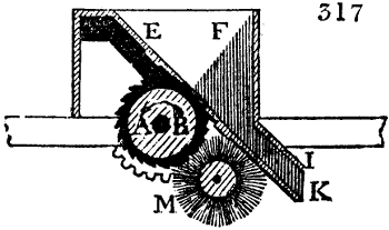
Fig. 317. A B, is a roller, about 9 inches in diameter, which revolves in the direction of the arrow. This cylinder consists of a parallel series of oblique pointed circular saws made fast to one axis, and parted from each other by wooden rings nearly one inch and a half in thickness. Above the cylinder is a kind of hopper E F, into which ginner throws the seed cotton, which falls upon a grating, up though which small segments of the saw-teeth project, so as to lay hold of the fibres in their revolution, and pull them through, while the seeds being thus separated, roll down the slope of the grid, to be discharged from the spout I K. M is a cylindrical brush placed below the grating, which revolves against the saw teeth, so as to clear them of the adhering cotton filaments.
The willow, which was originally a cylindrical willow basket, whence its name, but is now a box made of wood, with revolving iron spikes, is the first apparatus to which cotton wool is exposed, after it has been opened up, picked, and sorted by hand or a rake, in what is called a bing. The willow exercises a winnowing action, loosens the large flocks, and shakes out much of the dirt contained in them. The frame of the willow is about 2 feet wide, and turns with its spikes at the rapid rate of 600 revolutions per minute, whereby it tosses the cotton about with great violence. The heavy impurities fall down through the grid bottom. It is exposed, however, for only a few minutes to the action of this machine. For factories which work up chiefly the coarser and fouler cottons of India, and Upland Georgia, the conical self-acting willow, as constructed by Mr. Lillie at Manchester, is much employed. In it, the cotton is put in at the narrow end of the truncated cone, which, being spiked, and revolving rapidly within a nearly concentric case upon a horizontal axis, wafts it on towards the wide end, while its impurities are partly shaken out through the grid or perforated bottom, and partly sucked up through revolving squirrel wire cages, by the centrifugal action of a fan. This is a powerful automatic engine, deserving the study of the curious, and is as safe as it is powerful. The cone of this huge machine makes from 400 to 600 turns per minute, and will clean 7200 pounds, or 24 bags, in a day.
After shaking out the grosser impurities by the willow, the cotton spinner proceeds to separate each individual filament of cotton wool from its fellow, so as to prepare it for carding, and to free it from every particle of foreign matter, whether lighter or heavier than itself. This second operation is performed by what are called batting (beating), scutching, and blowing machines, which are all now much the same, whatever difference of signification the name may have. Indeed, each machine not only beats, scutches, but blows. Fig. 318. exhibits a longitudinal section of a good blowing engine of modern construction. The machine is about 18 or 19 feet long, and three feet across within the case. The whole frame is made of cast-iron, lined with boards, forming a close box, which has merely openings for introducing the raw cotton wool, for taking out the cleansed wool, and removing the dust as it collects at the bottom. These doors are shut during the operation of the machine, but may be opened at pleasure, to allow the interior to be inspected and repaired.
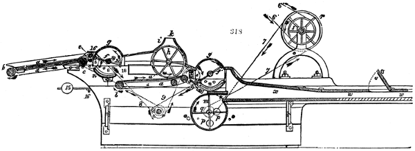
Fig. 318 enlarged (120 kB)
The introduction of the cotton is effected by means of an endless cloth or double apron, which moves in the direction of the arrow a a, at the left end of the figure, by passing round the continually revolving rollers at b and c. The two rollers at e, being the ones which immediately introduce the cotton into the jaws, as it were, of the machine, are called the feed rollers. The batting arm, or revolving diameter, f e, turns in the direction of the arrow, and strikes the flocks violently as they enter, so as to throw down any heavy particles upon the iron grating or grid at n, while the light cotton filaments are wafted onwards with the wind, from the rotation of the scutcher in the direction of arrow a′, along the second travelling apron, upon which the squirrel cage cylinder presses, and applies the cotton in the form of a lap. Above the cylindric cage h, which turns in the direction of its arrow, there is a pipe k, the continuation of the case i. This pipe, though broken off in the figure, communicates by a branch pipe with an air-sucking fan ventilator, not seen in this figure, but explained under Foundry. The cage h, by its rotation, presses down, as we have said, the half-cleaned cotton upon the cloth a′, which carries it forward to the second scutcher f′, by the second set of feed rollers e′. The second scutcher throws down the heavy dust upon the second grid n′, through which it falls upon the bottom of the case. The first scutcher makes about 1280 strokes of each of its two arms in a minute; the second 1300. The feed rollers for each are fluted. The feed cloth is either sustained by a board, or is made of parallel spars of wood, to secure it against bagging, which would render the delivery of the cotton irregular. The feed rollers make 8 turns in the minute, and as their diameter is 11⁄2 inches, they will introduce 8 times their circumference, or 37·7 inches of the cotton spread upon the apron in that time. Upon every 12th part of an inch of the cotton, therefore, nearly 3 blows of the scutcher arm will be applied. The second feed rollers move relatively with more slowness, so that for every 2·4 blows of the scutcher, only one twelfth of an inch of cotton wool is presented.
The fan is inclosed in a cylindrical case. The wings or vanes revolve from 120 to 150 times in the minute; and while they throw the air out with nearly this velocity at their excentric outlet in the circumference, they cause it to enter, with equal velocity, at the centre. With this centre the squirrel cage is connected by a pipe, as above stated. The sound filaments of the cotton are arrested by the sieve surface of the cylindric cage, and nothing but the broken fragments and the light dust can pass through.
The cotton wool in the blowing machine is wafted by the second scutcher into the space x, w w, provided with a fine grid bottom; or it is sometimes wound up there by rollers into a lap.
In fig. 318. an additional ventilator is introduced beneath at m, o o, to aid the action of the scutchers in blowing the cotton onwards into the oblong trough a. The outlet of that fan is at t; and it draws in the air at its axis q. u and v, are two doors or lids for removing the cleaned cotton wool. This last fan is suppressed in many blowing machines, as the scutching arms supply a sufficient stream of air. The dotted lines show how the motion is transmitted from the first mover at s, to the various parts of the machine. 6′ 6′ represent the bands leading to the main shafting of the mill. A machine of this kind can clean fully 600 pounds of short-stapled cotton wool in a day, with the superintendence of one operative, usually a young woman, to distribute the cotton upon the first feed cloth.
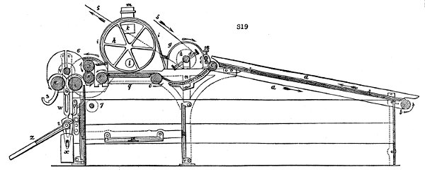
Fig. 319 enlarged (123 kB)
The second Blowing machine is usually called a lap machine, because, after blowing and scutching the cotton, as above described, it eventually coils the fleece upon a wooden roller at the delivering end of the apparatus. It is sometimes also called a spreading machine. A section of it is shown in fig. 319. The breadth of this machine is about 3 feet as the lap formed is prepared for the usual breadth of the breaker cards, namely 3 feet. Where the cards are only 18 inches broad, the lap machine is also made of the same breadth. In the figure we see the feed-cloth, the scutching barrel, the squirrel suction, and spreading cage, and the rollers for coiling up the lap. The lever shown below is for removing the pressure weight from the axis of the lap rollers, when a full one is to be removed, and replaced by an empty one. m, at the top, is the commencement of the pipe which leads to the suction fan, or ventilator. The thickness of the lap in this machine must be nicely regulated, as it determines, in a great measure, the grist of the card ends, and even the rovings. In 12 hours such a lap machine will prepare 650 pounds of cotton.
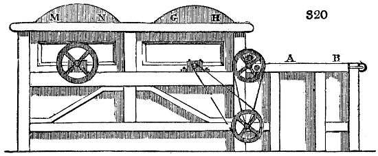
Fig. 320. is the first scutching machine, now never seen except in the oldest factories. A B is the feed cloth; G H and M N are the two scutcher frames.
Carding is the next operation in a cotton factory. Cards are destined to disentangle the individual filaments from each other, and to lay them lengthwise, instead of being doubled up and convoluted, as they usually are in leaving the blowing and lap machines. Carding consists in the mutual action of two opposite surfaces, which are studded thick with oblique angled hooks. The wires of which these hooks are made must be very hard drawn in order to render them stiff and elastic. The middle part of the figures shows one of the staples or double teeth, the structure of which has been partly explained under Card. Suppose a, fig. 321. to be a piece of a card fillet, and b to be another piece, each being made fast with pins to a board; the teeth of these two cards are set in opposite directions, but are very near together, and parallel. Now suppose a flock or tuft of cotton placed between two such bristling surfaces. Let a be moved in the direction of its arrow, and let b be moved in the opposite direction, or even let it remain at rest. Every filament of the cotton will be laid hold of by each set of teeth, when their surfaces are thus drawn over each other; the teeth of a will pull them in a forward direction, while those of b will tend to retain them, or to pull them backwards. The loops or doublings will, by both movements, be opened or drawn out, so that the flocks will be converted into rows of parallel filaments, lying alongside or before each other. Each tooth will secure to itself one or more of them, and by the friction of its sides, as well as the hooks of its points, will draw them to their utmost elongation. Though one stroke of the opposite cards be inadequate to produce this equable arrangement, yet many repeated strokes must infallibly accomplish the end in view, of laying the fibres parallel.
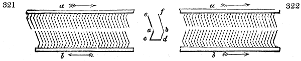
Let us suppose this end effected, and that all the fibres have been transferred to the card a, a transverse stroke of b will draw over to it a certain number of them, and indeed at each stroke there will be a new partition between the two cards, with increased parallelism, but still each card will retain a great deal of the cotton. To make one card strip another, the teeth of one of them must be placed in a reverse position, as shown in fig. 322.
If a be now drawn in the direction of its arrow along the face of b, it will inevitably comb out all, or almost all, the filaments from it, since the hooks of b have, in this position, no power of retaining them. Even the doubled fibres or loops will slip over the sloping point of b, in obedience to the traction of a. By considering these two relative positions of the cards, which take place in hand cards, simply by reversing one of them, any person will be able to understand the play of a cylinder card against its flat top, or against another cylinder card, the respective teeth being in what we may call the teazing position of fig. 321.; and also the play of a cylinder card against the doffer cylinder, in what may be called the stripping position of fig. 322.
Cylinder cards, so essential to the continuity and dispatch of cotton factory labour, were the ingenious invention of Lewis Paul of Northampton, but were greatly improved and brought into nearly their present operative state by Sir Richard Arkwright. A carding engine consists of one or more cylinders, covered with card-leather (sometimes called card cloth), and a set of plane surfaces similarly covered, made to work against each other, but so that their points do not come into absolute contact. Some cards consist entirely of cylinders, the central main cylinder being surrounded by a series of smaller ones called urchins or squirrels. These are used solely for preparing the coarser stapled cotton, and sheep’s wool for the wool spinner.
Fig. 323. represents a card of excellent construction, which may be called a breaker and finisher, as it is capable of working up the fleece roll of the lapping machine directly into a card-end or riband fit for the drawing machine. In fine spinning mills there are always, however, two cards; one coarser, called a breaker, which turns off the cotton in a broad fleece of extreme thinness, which is lapped round a cylinder; and constitutes the material presented to the finisher card, which has teeth of a finer construction.
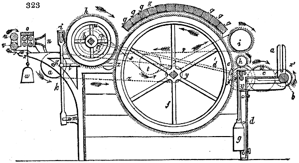
a is one of the two upright slots, which are fixed at each side of the engine for receiving the iron gudgeons of the wooden cylinders round which the fleece of the lapping machine is rolled. The circumference of this coil rests upon a roller b, which is made to turn slowly in such a direction as to aid the unfolding of the lap by the fluted cylinders e. The lap proceeds along the table seen beneath the letter c, in its progress to the fluted rollers, which are an inch and one-sixth in diameter, and have 28 flutings in their circumference. g is a weight which hangs upon the axis of the upper roller, and causes it to press upon the under one: f is the main card drum; g g g, the arch formed by the flat top cards; h, the small card cylinder for stripping off the cotton, and therefore called the doffer, as we have said; i, the doffer-knife or comb for stripping the fleecy web from the doffer; k l q m, the lever mechanism for moving these parts. At d there is a door for permitting the tenter to have access to the interior of the engine, and to remove whatever dirt, &c. may happen to fall into it. In fig. 324. we see the manner of fixing the flat tops g g over the drum; and for making the matter clearer, three of the tops are removed. Upon the arched cast-iron side of the frame, a row of strong iron pins k are made fast in the middle line; and each top piece has, at each of its ends, a hole, which fits down upon two such opposite pins. l l are screws whose heads serve as supports to the tops, by coming into contact with the bottom of the holes, which are not of course bored through the wood of the tops. By turning the heads of these screws a little the one way or the other, the pins may be lengthened or shortened in any degree, so as to set the tops very truly in adjustment with the drum teeth revolving beneath them, h′ is the small runner or urchin, and i′ the large runner; both of which are spirally covered from end to end with narrow card fillets, in the same manner as the doffer. The main drum is on the contrary covered with card cloth, in strips laid on parallel to its axis, with interjacent parallel smooth leather borders. The teeth of these several cards are set as represented in the figure, and their cylinders revolve as the arrows indicate. The runners as well as the doffer cylinder may be set nearer to or farther from the drum f; but the screws intended for this adjustment are omitted in the drawings, to avoid confusion of the lines.
The card-end or fleece taken off the doffer h by the crank and comb mechanism i k m, passes through the tin plate or brass funnel n, fig. 323., whereby it is hemmed in and contracted into a riband, which is then passed through between a pair of drawing rollers o. It is next received by the rollers u v, which carry it off with equable velocity, and let it fall into the tin cans placed below, or conduct it over a friction pulley, to be wound along with many other card-ends upon a lap roller or large bobbin. The latter mechanism is not shown in this figure. A sloping curved tin or brass plate, channelled or ridged along its surface, conducts the card ribands separately; there are two smooth iron rollers for condensing the several ribands, and a wooden pin round which the ribands are lapped, resting between two leather-covered rollers, one of which receives motion from mill geering, and imparts it by friction to the lap roller over it. The iron ends of the lap roller lie in upright slots, which allow them freedom to rise as the roller gets filled with fleece.
The two pairs of rollers at o, effect the extension of the card-end, and reduce its size. The under rollers are made of iron and fluted; the upper ones are also made of iron, but they are covered with a coat of leather, nicely glued on over a coat of flannel, which two coats render them both smooth and elastic. Two weights, w, press the upper cylinders steadily down upon the under ones. Between the first and second pair there is a certain interval, which should be proportioned to the length of the cotton staple. The second, or that furthest from the funnel, revolves with greater velocity than the first, and therefore turns out a greater length of riband than it receives from its fellow; the consequence is a corresponding extension of the riband in the interval between the two pairs of rollers.
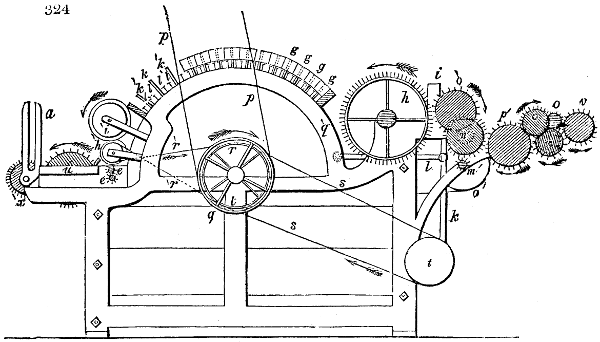
The motions of the several parts of the engine are effected in the following way. The band, p p, fig. 324., which comes down from the pulley upon the main shaft near the ceiling of the work-room, drives, by means of the pulley q, the drum f, fig. 323., with a velocity of from 120 to 140 revolutions in a minute. From another pulley r, on the axis of the drum, the axis of t is driven by the band s working round the pulley t on its end. This shaft drives the crank and lever mechanism of the stripper knife i. A third pulley of the same size as r is fixed just within the frame to the other end of the drum, and from it a crossed or close band r′ goes to a pulley upon the small runner h′, to give this its rapid rotation. Upon the opposite end of the engine in fig. 323., these wheels and pulleys are marked with dotted lines. Here we may observe, first, a pulley y upon the drum, and a pulley a′, which receives motion from it by means of the band z. The axis of a′, carries in front a pinion m′, which sets in motion the wheel n′. The latter imparts motion, by means of a pinion and intermediate wheel o′, to the wheel h on the doffer cylinder, and consequently to that cylinder on the one hand; and it turns, by the carrier wheel p′, a wheel x, whose axis is marked also with x in fig. 323., upon the other hand. The axis of x′, fig. 323., carries, towards the middle of the engine, a very broad wheel, which is represented by a small dotted circle. The toothed wheel v of the smooth roller v′, fig. 323., and the two toothed wheels o o, fig. 324., of the under rollers o o, fig. 323., work into that broad wheel. The wheel of the second or delivery fluted roller is seen to be smaller than that of the first, by which means the difference of their velocities is obtained. The large runner i is driven from the main drum pulley, by means of the band s′, and the pulley u′, fig. 323. The said band is crossed twice, and is kept in tension by the pulley t′, round which it passes. The motion of the fluted rollers e, which feed in the cotton fleece, is effected by means of a bevel wheel b′ on the end of the doffer, which works into a similar wheel c′ on the oblique axis d′ (dotted lines across the drum), of the pinion e′ upon the lower end of the same axis which turns the wheel f′, upon the under feed roller.
Each of the feed rollers, fig. 324., bears a pinion e e at one end, so that the upper roller turns round with the under one. The roller b, fig. 323., is set in motion by means of its wheel x′; which is driven by a wheel v′ on the other end of the under feed roller, through the intervention of the large carrier wheel w′. The original or first motion of b must be as quick as that of the fluted feed rollers e, in order that the former may uncoil as much lap as the latter can pass on.
The annexed table exhibits the proper velocities of the different cylinders and rollers of the carding engine, which, however, are not invariable, but may be modified according to circumstances, by changing the pinions e′, fig. 323., and w′, according to the quality or length of the cotton staple. The velocities stated in the table will be obtained when the pulley a′, fig. 323., is made greater than y in the proportion of 3 to 2, and the wheels and pinions have the following number of teeth: m′, 18; n′, 50; its pinion, 18; h, 128; x, 24; the broad wheel upon the shaft of x, 37 teeth; the wheel o of the first fluted roller, 35; that of the second, 21; v, 44; b′ and e′, 54; e′, 10; f′, 63.
Names of the parts. Diameter in inches. Circum- ference in inches. Revolutions in one minute. Velocity.
Drum f 35 109 ·9 130 142 ·87
Doffer h 14 43 ·96 4 ·38 192 ·5
Runner or urchin i′ 6 ·25 19 ·62 5 · 98 ·1
Ditto h′ 3 ·5 11 · 470 · 5170 ·
Fluted feed roller e 1 ·167 3 ·664 0 ·696 2 ·55
First drawing roller o 1 · 3 ·14 68 ·71 215 ·75
Second ditto 1 ·167 3 ·664 114 ·52 419 ·6
Smooth delivery roller v 2 ·5 7 ·85 54 ·66 429 ·08
The operation of the runners, h′ and i′, becomes very plain on comparing their speed with one another and with that of the main-drum, and taking into account the direction of the card teeth. The cotton wool, taken off from the feed-rollers by the drum, is caught by the opposite teeth of the large runner i′, which, on account of its slower surface rotation (98 inches per minute) may be considered to be at rest with reference to the drum, and therefore, by holding the cotton in its teeth, will commence its carding. The small runner h′, in consequence of its greater surface velocity (5170 inches per minute) will comb the cotton-wool back out of the teeth of the large runner, but it will give it up in its turn to the swifter teeth of the drum, which, in carrying it forwards, encounters the teeth of the top cards, and delivers up the filaments to their keeping for some time. We thus see how essential the runners are to the perfection as well as to the acceleration of the carding process for ordinary cotton wool, though for the slenderer and longer filaments of the sea-island kind they are not so well adapted. In cleaning the carding-engines the little runner must be looked to every time that the drum is examined. The large runner and the doffer require to be cleaned together. The quantity of cotton spread upon the feed-cloth, the velocity of it, and of the drawing-rollers, must all be carefully adjusted to the grist of the yarn intended to be spun.
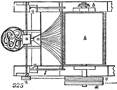
Suppose the sizes and velocities to be as represented in the preceding table, that the engine is a double card 36 inches broad, and that it is furnished with a lap from the lap-machine of which 30 feet in length weigh 5 lbs. In one minute the surface of the feed-rollers, e, passes 2·55 inches of that lap onwards; in the same time the main drum f will work it off. To card the whole 30 feet, therefore, 141 minutes, or 2 hours and 21 minutes will be required. In this time the circumference of the rollers, u v, moves through a space of 141 × 42,908 in. = 5042 ft., and delivers a card-end of that length, weighing 5 lbs., minus 6 per cent. for waste, that is 4 lbs. 111⁄2 oz. One pound will form a riband 1072 feet long, being, according to the English mode of counting, about number 1⁄3, or 0·357. The extension of the cotton-fleece to this degree proceeds as follows:—In the 141 minutes which the feed-rollers take to introduce the 30 feet of lap, the doffer, h, makes 617·58 revolutions, and the comb, or doffer knife, i, detaches from the doffer teeth, a thin fleecy web of 2262 feet in length. The first drawing pair of fluted rollers, by its quick motion, with the aid of the funnel, m, converts this fleece into a riband 2535 feet long. The second pair of the fluted rollers extends this riband to 4390 feet, since their surface velocity is greater than the first pair in that proportion. The slight elongation (of only 112 feet, or about 1⁄44) which takes place between the delivery fluted rollers and the smooth cylinders, v, u, serves merely to keep the card-end steadily upon the stretch without folding. Fig. 325. is a plan of the card and the fleece, where h is the cylinder, n is the funnel, u the pressing rollers, and h′ the card-ends in the can.
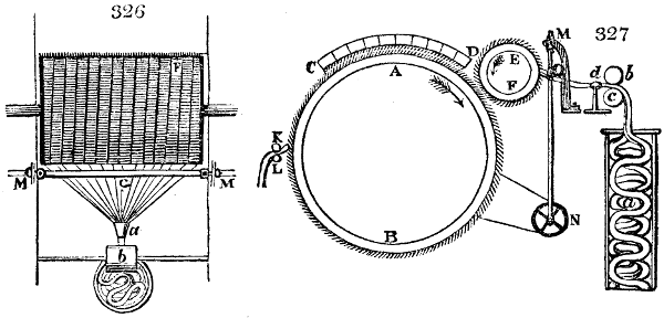
Figs. 326, 327. represent skeletons of the old cards to facilitate the comprehension of these complex machines. Fig. 326. is a plan; F is the main drum; M M is the doffer knife or comb; G, the carded fleece hemmed in by the funnel a, pressed between the rollers b, and then falling in narrow fillets into its can. Fig. 327. K L are the feed rollers; A B, the card drum; C D, the tops; E F, the doffer card; M N, the doffer knife; d, b, c, the card-end passing between compressing rollers into the can a.
The drawing and doubling are the next operation. The ends, as they come from the cards, are exceedingly tender and loose, but the filaments of the cotton are not as yet laid so parallel with each other as they need to be for machine spinning. Before any degree of torsion therefore be communicated, a previous process is required to give the filaments a level arrangement in the ribands. The drawing out and doubling accomplish this purpose, and in a manner equally simple and certain. The means employed are drawing-rollers, whose construction must here be fully explained, as it is employed in all the following machines; one example of their use occurred, indeed, in treating of the cards.
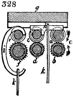
Let a and b, fig. 328., represent the section of two rollers lying over each other, which touch with a regulated pressure, and turn in contact upon their axes, in the direction shown by the arrows. These rollers will lay hold of the fleecy riband presented to them at a, draw it through between them, and deliver it quite unchanged. The length of the piece passed through in a given time will be equal to the space which a point upon the circumference of the roller would have percured in the same time; that is, equal to the periphery of one of the rollers multiplied by the number of its entire revolutions. The same thing holds with regard to the transmission of the riband through between a second pair of rollers, c, d, and a third, e, f. Thus the said riband issues from the third pair exactly the same as it entered at a, provided the surface speed of all the rollers be the same. But if the surface speed of c and d be greater than that of a and b, then the first-named pair will deliver a greater length of riband than the last receives and transmits to it. The consequence can be nothing else in these circumstances than a regulated drawing or elongation of the riband in the interval betwixt a, b, and c, d, and a condensation of the filaments as they glide over each other, to assume a straight parallel direction. In like manner the drawing may be repeated by giving the rollers, e, f, a greater surface speed than that of the rollers, c and d. This increase of velocity may be produced, either by enlarging the diameter, or by increasing the number of turns in the same time, or finally by both methods conjoined. In general the drawing-machine is so adjusted, that the chief elongation takes place between the second and third pairs of rollers, while that between the first and second is but slight and preparatory. It is obvious, besides, that the speed of the middle pair of rollers can have no influence upon the amount of the extension, provided the speed of the first and third pair remains unchanged. The rollers, a, b, and c, d, maintain towards each other continually the same position, but they may be removed with their frame-work, more or less, from the third pair, e, f, according as the length of the cotton staple may require. The distance of the middle point from b and d, or its line of contact with the upper roller, is, once for all, so calculated, that it shall exceed the length of the cotton filaments, and thereby that these filaments are never in danger of being torn asunder by the second pair pulling them while the first holds them fast. Between d and f, where the greatest extension takes place, the distance must be as small as it can be without risk of tearing them in that way; for thus will the uniformity of the drawing be promoted. If the distance between d and f be very great, a riband passing through will become thinner, or perhaps break in the middle; whence we see that the drawing is more equable, the shorter is the portion submitted to extension at a time, and the nearer the rollers are to each other, supposing them always distant enough not to tear the staple.
The under rollers b d f are made of iron, and, to enable them to lay firmer hold of the filaments, their surfaces are fluted with triangular channels parallel to their axes. The upper rollers, a c e, are also made of iron, but they are smooth, and covered with a double coating, which gives them a certain degree of softness and elasticity. A coat of flannel is first applied by sewing or gluing the ends, and then a coat of leather in the same way. The junction edges of the leather are cut slanting, so that when joined by the glue (made of isinglass dissolved in ale) the surface of the roller may be smoothly cylindrical. The top rollers are sometimes called the pressers, because they press by means of weights upon the under ones. These weights are suspended to the slight rods k k′; of which the former operates on the roller e alone, the latter on the two rollers a and e together. For this purpose the former is hung to a C shaped curve i, whose upper hook embraces the roller e; the latter to a brass saddle h, which rests upon a and c. A bar of hard wood, g, whose under surface is covered with flannel, rests, with merely its own weight, upon the top rollers, and strips off all the loose hanging filaments. Similar bars with the same view are made to bear up under the fluted rollers b d f, and press against them by a weight acting through a cord passing over a pulley. Instead of the upper dust-covers, light wooden rollers covered with flannel are occasionally applied.
Were the drawing of a riband continued till all its fibres acquired the desired degree of parallelism, it would be apt, from excessive attenuation, to tear across, and thereby to defeat the purpose of the spinner. This dilemma is got rid of in a very simple way, namely, by laying several ribands together at every repetition of the process, and incorporating them by the pressure of the rollers. This practice is called doubling. It is an exact imitation of what takes place when we draw a tuft of cotton wool between our fingers and thumb in order to ascertain the length of the staple, and replace the drawn filaments over each other, and thus draw them forth again and again, till they are all parallel and of nearly equal length. The doubling has another advantage, that of causing the inequalities of thickness in the ribands to disappear, by applying their thicker to their thinner portions, and thereby producing uniformity of substance.
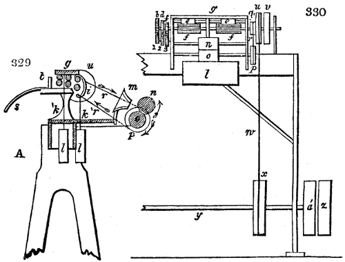
The drawing frame, as shown in section in figs. 328. 330., and in a back view in fig. 329., will require, after the above details, little further explanation. l l are the weights which press down the top rollers upon the under ones, by means of the rods k k′ and hook i. Each fluted roller is, as shown at f, fig. 329., provided in the middle of its length with a thinner smooth part called the neck, whereby it is really divided into two fluted portions, represented by e e in the figure. Upon this middle neck in the pressure rollers, the hook i and the saddle h immediately bear, as shown in the former fig. 328. The card-ends, to the number probably of six, are introduced to the drawing frame either from tin cans, placed at e e, fig. 330., and at A, fig. 329., or from lap-bobbins; and, after passing through it, the ribands or slivers are received either into similar tin cans, as g, or upon other lap-bobbins upon the other side. These appendages may be readily conceived, and are therefore not exhibited in all the drawings. Three of the slivers being laid together, are again introduced to the one fluted portion a b, fig. 328., and three other slivers to the other portion. The sloping curved tin or brass plate s, fig. 329., with its guide pins t, serves to conduct the slivers to the rollers. When the two threefold slivers have passed through between the three pairs of rollers, and been thereby properly drawn, they run towards each other in an oblique direction, behind the last roller pair e f, fig. 328., and unite, on issuing through the conical funnel m, fig. 329., into a single riband or spongy sliver; which is immediately carried off with equable velocity by two smooth cast-iron rollers, n o, fig. 329. and 330. and either dropped into a can, or wound upon a large bobbin. The surface speed of these rollers is made a trifle greater than that of the delivery drawing rollers, in order to keep the portion of sliver between them always in an extended state. Four fluted drawing portions are usually mounted in one drawing frame, which are set a-going or at rest together. To save all unnecessary carrying of the cans from the back to the front of the frame, the drawing heads are so placed, that the first and third, discharge their slivers at the one side, and the second and fourth at the other. By this arrangement, the cans filled behind one head, are directly pushed aside in front of the next drawing head; by which alternate distribution the work goes on without interruption.
The fast pulley u, fig. 330., by which the whole machine is driven, derives its motion from the main shaft of the mill by means of the band w. The similar pulley x, which sits loose upon the axis, and turns independently of it, is called the loose pulley; both together being technically styled riggers. When the operative desires to stop the machine, he transfers the band from the fast to the loose pulley by means of a lever, bearing a fork at its end, which embraces the band. Upon y, four pulleys such as x are fixed, each of which sets in motion a drawing head, by means of a band like w going round the pulleys x and u. On account of the inverted position of the heads, which requires the motion of u to be inverted, the bands of the first and third heads are open, but those of the second and fourth are crossed. Every head is provided with a loose pulley v, as well as the fast pulley u, in order to make the one stop or move without affecting the others. The shaft of the pulley u is the prolonged shaft of the backmost fluted roller f. It carries besides a small pulley q, which, by means of the band r, and the pulley p, fig. 329., sets in motion the undermost condensing roller o. The upper roller n, presses with its whole weight upon it, and therefore turns by friction. The toothed wheel-work, by which the motions are communicated from the backmost fluted roller to the middle and front ones, are seen in fig. 330.
The wheel f, fig. 328., of 20 teeth, works in a 44-toothed carrier-wheel, on whose axis there are two smaller wheels; 2 with 26 teeth, and 1 with 22 teeth. The wheel d, fig. 330., of the middle roller, and the wheel b of the front roller, are set in motion by other carrier wheels; the first has 27 teeth, and the last 40. For every revolution of b, the roller d makes nearly 13⁄4 turns, and the roller f, 4 revolutions. The top rollers revolve, as we have stated, simply by the friction of contact with the lower ones. Now suppose the diameter of the rollers b and d to be 1 inch or 12 lines, that of f, 11⁄4 inches or 15 lines, the surface velocities of the three pairs of rollers in the series will be as 1, 13⁄4, and 5. Every inch of the cotton sliver will be therefore extended between the first and second pair of rollers into 13⁄4 inches, and between the second and third or delivery pair into 5 inches; and after the sliver has passed through all the four drawing heads, its length will be increased 625 times = 5 × 5 × 5 × 5.
The further the drawing process is pushed, the more perfectly will its object be accomplished; namely the parallelism of the filaments. The fineness of the appearance of the sliver after the last draught depends upon the number of doublings conjointly with the original fineness and number of drawings. The degree of extension may be increased or diminished, by changing the wheels in fig. 330., for others with a different number of teeth. Thus the grist or fineness of the sliver may be modified in any desired degree; for, when the subsequent processes of the mill remain the same, the finer the drawings the finer will be the yarn. For spinning coarse numbers or low counts, for example, six card-ends are usually transmitted through the first drawing head, and converted into one riband. Six such ribands again form one in the second draught; six of these again go together into the third sliver; and this sliver passes five-fold through the last draught. By this combination 1080 of the original card-ends are united in the finished drawn sliver = 6 × 6 × 6 × 5. The fineness of the sliver is, however, in consequence of these doublings not increased but rather diminished. For, by the drawing, the card-end has been made 625 times longer, and so much smaller; by the doubling alone it would have become 1080 times thicker; therefore the original grist is to the present as 1, to the fraction 625⁄1080; that is, supposing 1072 feet of the riband delivered by the card to weigh one pound, 625 feet, the sliver of the last drawing, will also weigh a pound, which corresponds in fineness to number 0·24, or nearly 1⁄4.
The rearmost or last drawing roller has a circumference of nearly 4 inches, and makes about 150 revolutions per minute; hence, each of these drawing heads may turn off 35,000 feet of sliver in 12 hours.
Some manufacturers have lately introduced a double roller beam, and a double draught at the same doubling, into their drawing frames. I have seen this contrivance working satisfactorily in mills where low counts were spun, and where the tube roving frame was employed; but I was informed by competent judges, that it was not advisable where a level yarn was required for good printing calicoes.
The loss which the cotton suffers in the drawing frame is quite inconsiderable. It consists of those filaments which remain upon the drawing rollers, and collect, in a great measure, upon the flannel facing of the top and bottom cleaner bars. It is thrown among the top cleanings of the carding engine. When from some defect in the rollers, or negligence in piecing the running slivers, remarkably irregular portions occur in the ribands, these must be torn off, and returned to the lap machine to be carded anew.
The fifth operation may be called the first spinning process, as in it, the cotton sliver receives a twist; whether the twist be permanent as in the bobbin and fly frame, or be undone immediately, as in the tube-roving machine. In fact, the elongated slivers of parallel filaments could bear little further extension without breaking asunder, unless the precaution were taken to condense the filaments by a slight convolution, and at the same time to entwine them together. The twisting should positively go no further than to fulfil the purpose of giving cohesion, otherwise it would place an obstacle in the way of the future attenuation into level thread. The combination of drawing and twisting is what mainly characterizes the spinning processes, and with this fifth operation therefore commences the formation of yarn. As however a sudden extension to the wished-for fineness is not practicable, the draught is thrice repeated in machine spinning, and after each draught a new portion of torsion is given to the yarn, till at last it possesses the degree of fineness and twist proportioned to its use.
The preliminary spinning process is called roving. At first the torsion is slight in proportion to the extension, since the solidity of the still coarse sliver needs that cohesive aid only in a small degree, and looseness of texture must be maintained to facilitate to the utmost the further elongation.
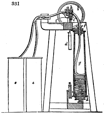
Fig. 331. is a section of the can roving frame, the ingenious invention of Arkwright, which till within these 14 years was the principal machine for communicating the incipient torsion to the spongy cord furnished by the drawing heads. It differs from that frame in nothing but the twisting mechanism; and consists of two pairs of drawing rollers, a and b, between which the sliver is extended in the usual way; c are brushes for cleaning the rollers; and d is the weight which presses the upper set upon the lower. The wiping covers (not shown here) rest upon a b. The surface speed of the posterior or second pair of rollers is 3, 4, or 5 times greater than that of the front or receiving pair, according to the desired degree of attenuation. Two drawn slivers were generally united into one by this machine, as is shown in the figure, where they are seen coming from the two cans e e, to be brought together by the pressure rollers, before they reach the drawing rollers a b. The sliver, as it escapes from these rollers, is conducted into the revolving conical lantern g, through the funnel f at its top. This lantern-can receives its motion by means of a cord passing over a pulley k, placed a little way above the step on which it turns. The motion is steadied by the collet of the funnel f, being embraced by a brass busk. Such a machine generally contained four drawing heads, each mounted with two lanterns; in whose side there was a door for taking out the conical coil of roving.
The motion imparted to the back roller by the band pulley or rigger m, was conveyed to the front one by toothed wheel work.
The vertical guide pulley at bottom n, served to lead the driving band descending from the top of the frame round the horizontal whorl or pulley upon the under end of the lantern. The operation of this can-frame was pleasing to behold; as the centrifugal force served both to distribute the soft cord in a regular coil, and also to condense a great deal of it most gently within a moderate space. Whenever the lantern was filled, the tenter carried the roving to a simple machine, where it was wound upon bobbins by hand. Notwithstanding every care in this transfer, the delicate texture was very apt to be seriously injured, so as to cause corresponding injuries in every subsequent operation, and in the finished yarn. Messrs. Cocker and Higgins, of Salford, had the singular merit, as I have said, of superseding that beautiful but defective mechanism, which had held a prominent place in all cotton mills from almost the infancy of the factory system, by the following apparatus.
The Bobbin and Fly frame is now the great roving machine of the cotton manufacture; to which may be added, for coarse spinning, the tube roving frame. Of such a complicated machine as the bobbin and fly frame, it is not possible to give an adequately detailed description in the space due to the subject in this Dictionary. Its mechanical combinations are however so admirable as to require such an account as will make its functions intelligible by the general reader.
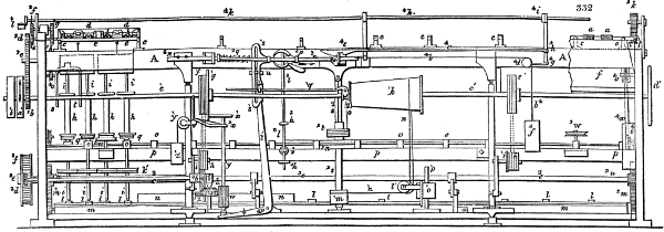
Fig. 332 enlarged (367 kB)
Fig. 332. exhibits a back view of this machine; and fig. 333. a section of some of the parts not very visible in the former figure. The back of the machine is the side at which the cotton is introduced between the drawing rollers.
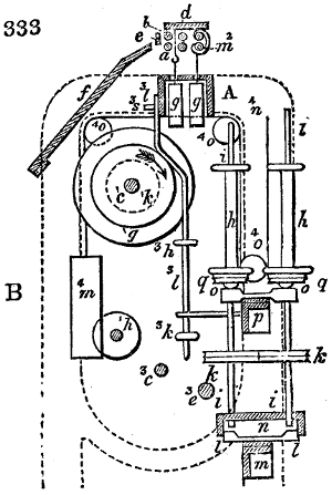
The cans, or lap-bobbins filled with slivers at the drawing frame, are placed in the situation marked B, fig. 333., in rows parallel with the length of the machine. The sliver of each can or the united slivers of two contiguous cans are conducted upwards along the surface of a sloping board f, and through an iron staple or guide e, betwixt the usual triple pair of drawing rollers, the first of which is indicated by a, b. In fig. 332., for the purpose of simplifying the figure, the greater part of these rollers and their subordinate parts are omitted. After the slivers have been sufficiently extended and attenuated between the rollers, they proceed forwards, towards the spindles i i i, where they receive the twist, and are wound upon the bobbins h. The machine delineated contains thirty spindles, but many bobbin and fly frames contain double or even four times that number. Only a few of the spindles are shown in fig. 332., for fear of confusing the drawing.

With regard to the drawing functions of this machine, I have already given abundant explanation, so far as the properties and operation of the rollers are concerned. The frame-work of this part of the machine, called the roller-beam, is a cast iron bench, upon which nine bearers c, are mounted for carrying the rollers. The fluted rollers a a a, fig. 334., are constructed in four pieces for the whole length, which are parted from each other by thinner smooth cylindric portions z, called necks. Seven such partings for four rollers, and one parting for two rollers, constitute together the 30 fluted rollers of which the whole series consists. The coupling of these roller subdivisions into one cylinder, is secured by the square holes x, and square pins y, fig. 334., which fit into the holes of the adjoining subdivision. The top or pressure rollers b, are two-fold over the whole set; and the weighted saddle presses upon the neck w, which connects every pair, as was already explained under fig. 329. These weights g, g, fig. 333., are applied in this as in the drawing frame; d, are the bars faced with flannel for cleaning the top rollers. A similar bar is applied beneath the rollers, to keep the flutings clean.
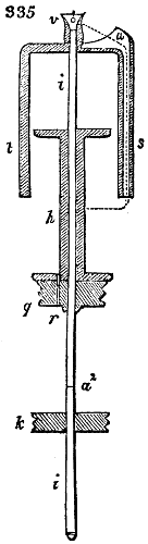
The structure and operation of the spindles i, may be best understood by examining the section fig. 335. They are made of iron, are cylindrical from the top down to a2, but from this part down to the steel tipt rounded points they are conical. Upon this conical portion there is a pulley k, furnished with two grooves in its circumference, in which the cord runs that causes the spindle to revolve. The wooden bobbin h, is slid upon the cylindrical part, which must move freely upon it, as will be presently explained. To the bobbin another two-grooved pulley or whorl q is made fast by means of a pin r, which passes through it; by removing this pin, the bobbin can be instantly taken off the spindle. The upper end of the spindle bears a fork s t, which may be taken off at pleasure by means of its left-handed screw; this fork or flyer, has a funnel-formed hole at v. One arm of the fork is a tube s, u, open at top and bottom; the leg t, is added merely as a counterpoise to the other. In fig. 333., for the sake of clearness, the forks or flyers of the two spindles here represented are left out; and in fig. 332. only one is portrayed for the same reason. It is likewise manifest from a comparison of these two figures that the spindles are alternately placed in two rows, so that each spindle of the back range stands opposite the interval between two in the front range. The object of this distribution is economy of space, as the machine would need to be greatly longer if the spindles stood all in one line. If we suppose the spindles and the bobbins (both of which have independent motions) to revolve simultaneously and in the same direction, their operation will be as follows: The sliver properly drawn by the fluted rollers, enters the opening of the funnel v, proceeds thence downwards through the hole in the arm of the fork, runs along its tube u, s, and then winds round the bobbin. This path is marked in fig. 335. by a dotted line.
The revolution of the spindles in the above circumstances effects the twisting of the sliver into a soft cord; and the flyer s, t, or particularly its tubular arm s, lays this cord upon the bobbin. Were the speed of the bobbins equal to that of the spindles, that is, did the bobbin and spindle make the same number of turns in the same time, the process would be limited to mere twisting. But the bobbin anticipates the flyers a little, that is, it makes in a given time a somewhat greater number of revolutions than the spindle, and thereby effects the continuous winding of the cord upon itself. Suppose the bobbin to make 40 revolutions, while the spindle completes only 30; 30 of these revolutions of the bobbin will be inoperative towards the winding-on, because the flyers follow at that rate, so that the cord or twisted sliver will only be coiled 10 times round the bobbin, and the result as to the winding-on will be the same as if the spindle had stood still, and the bobbin had made 40 - 30 = 10 turns. The 30 turns of the spindles serve, therefore, merely the purpose of communicating twist.
The mounting and operation of the spindles are obviously the same as they are upon the household flax wheel. In the bobbin and fly frame there are some circumstances which render the construction and the winding-on somewhat difficult, and the mechanism not a little complicated. It may be remarked in the first place, that as the cord is wound on, the diameter of the bobbin increases very rapidly, and therefore every turn made round it causes a greater length of roving to be taken up in succession. Were the motions of the bobbins to continue unchanged in this predicament, the increased velocity of the winding-on would require an increased degree of extension, or it would occasion the rupture of the cord, because the front fluted rollers move with uniform speed, and therefore deliver always the same length of sliver in the same time. It is therefore necessary to diminish the velocity of the bobbins, or the number of their turns, in the same proportion as their diameter increases, in order that the primary velocity may remain unchanged. Moreover, it is requisite for the proper distribution of the cord upon the bobbin, and the regular increase of its diameter, that two of its successive convolutions should not be applied over each other, but that they should be laid close side by side. This object is attained by the up and down sliding motion of the bobbin upon the spindle, to the same extent as the length of the bobbin barrel. This up and down motion must become progressively slower, since it increases the diameter of the bobbin at each range, by a quantity equal to the diameter of the sliver. What has now been stated generally, will become more intelligible by an example.
Let it be assumed that the drawing rollers deliver, in 10 seconds, 45 inches of roving, and that this length receives 30 twists. The spindles must, in consequence, make 30 revolutions in 10 seconds, and the bobbins must turn with such speed, that they wind up the 45 inches in 10 seconds. The diameter of the bobbin barrels being 11⁄2 inches, their circumference of course 41⁄2 inches, they must make 10 revolutions more in the same time than the spindles. The effective speed of the bobbins will be thus 30 + 10 = 40 turns in 10 seconds. Should the bobbins increase to 3 inches diameter, by the winding-on of the sliver, they will take up 9 inches at each turn, and consequently 45 inches in 5 turns. Their speed should therefore be reduced to 30 + 5 = 35 turns in 10 seconds. In general, the excess in number of revolutions, which the bobbins must make over the spindles, is inversely as the diameter of the bobbins. The speed of the bobbins must remain uniform during the period of one ascent or descent upon the spindle, and must diminish at the instant of changing the direction of their up and down motion; because a fresh range of convolutions then begins with a greater diameter. When, for example, 30 coils of the sliver or roove are laid in one length of the bobbin barrel, the bobbin must complete its vertical movement up or down, within 30 seconds in the first case above mentioned, and within 60 seconds in the second case.
The motions of the drawing rollers, the spindles, and bobbins, are produced in the following manner:—A shaft c′, fig. 332. and 333., extending the whole length of the machine, and mounted with a fly wheel d′, is set in motion by a band from the running pulley upon the shaft of the mill, which actuates the pulley a′. b′ is the loose pulley upon which the band is shifted when the machine is set at rest. Within the pulley a′, but on the outside of the frame, the shaft c′ carries a toothed wheel b2 with 50 teeth, which by means of the intermediate wheel c2 turns the wheel d2 upon the prolonged shaft of the backmost fluted roller (m2, fig. 333.) This wheel d2 has usually 54 teeth; but it may be changed when the roove is to receive more or less twist; for as the spindles revolve with uniform velocity, they communicate the more torsion the less length of sliver is delivered by the rollers in a given time. Upon the same shaft with d2, a pinion e2 of 32 teeth is fixed, which works in a wheel f2 of 72 teeth. Within the frame a change pinion g2 is made fast to the shaft of f2. This pinion, which has usually from 24 to 28 teeth, regulates the drawing, and thereby the fineness or number of the roving. It works in a 48-toothed wheel h2 upon the end of the backmost fluted roller a, fig. 333. The other extremity of the same roller, or, properly speaking, line of rollers, carries a pinion l2, furnished with 26 teeth, which, by means of the broad intermediate wheel k2, sets in motion the pinion i′2 of 22 teeth upon the middle roller. When the diameter of all the drawing rollers is the same, suppose 1 inch, their proportional velocities will be, with the above number of teeth in the wheel work, if g2 have 24 teeth, as 1 : 1·18 : 4·5; and the drawn sliver will have 41⁄2 times its original length. The front or delivery roller of the drawing frame is of late years usually made 11⁄4 or 13⁄8 inches in diameter. If 625 feet of the sliver from the drawing frame weighed one pound, 2790 feet of the roving will now go to this weight, and the number will be 1·12; that is, 1 hank and 12 hundredths to the pound. The front pair of fluted rollers makes about 90 revolutions, and delivers 282·6 inches of roving in the minute, when of one inch diameter.