P. (continued 3)
Reading edition
Pimento imported for home consumption, in 1835. 1836.
Duty—British possessions, 5d.; foreign, 1s. 3d. Lbs. 344,458. 400,914.
PINCHBECK, is a modification of brass; see that article and Copper.
PINE-APPLE YARN and CLOTH. In Mr. Zincke’s process, patented in December, 1836, for preparing the filaments of this plant, the Bromelia ananas, the leaves being plucked, and deprived of the prickles round their edges by a cutting instrument, are then beaten upon a wooden block with a wooden mallet, till a silky-looking mass of fibres be obtained, which are to be freed by washing from the green fecula. The fibrous part must next be laid straight, and passed between wooden rollers. The leaves should be gathered between the time of their full maturity and the ripening of the fruit. If earlier or latter, the fibres will not be so flexible, and will need to be cleared by a boil in soapy water for some hours; after being laid straight under the pressure of a wooden grating, to prevent their becoming entangled. When well washed and dried, with occasional shaking out, they will now appear of a silky fineness. They may be then spun into porous rovings, in which state they are most conveniently bleached by the ordinary methods.
Specimens of cambric, both bleached and unbleached, woven with these fibres, have been recently exhibited, which excited hopes of their rivalling the finest flax fabrics, but in my opinion without good reason, on account of their want of strength.
PINEY TALLOW, is a concrete fat obtained by boiling with water the fruit of the Vateria indica, a tree common upon the Malabar coast. It seems to be a substance intermediate between tallow and wax; partaking of the nature of stearine. It melts at 971⁄2° F., is white or yellowish, has a spec. grav. of 0·926; is saponified by alkalies, and forms excellent candles. Dr. Benjamin Babington, to whom we are indebted for all our knowledge of piney tallow, found its ultimate constituents to be, 77 of carbon, 12·3 of hydrogen, and 10·7 of oxygen.
PIN MANUFACTURE. (Fabrique d’épingles, Fr.; Nadelfabrik, Germ.) A pin is a small bit of wire, commonly brass, with a point at one end, and a spherical head at the other. In making this little article, there are no less than fourteen distinct operations.
1. Straightening the wire. The wire, as obtained from the drawing-frame, is wound about a bobbin or barrel, about 6 inches diameter, which gives it a curvature that must be removed. The straightening engine is formed by fixing 6 or 7 nails upright in a waving line on a board, so that the void space measured in a straight line between the first three nails may have exactly the thickness of the wire to be trimmed; and that the other nails may make the wire take a certain curve line, which must vary with its thickness. The workman pulls the wire with pincers through among these nails, to the length of about 30 feet, at a running draught; and after he cuts that off, he returns for as much more; he can thus finish 600 fathoms in the hour. He next cuts these long pieces into lengths of 3 or 4 pins. A day’s work of one man amounts to 18 or 20 thousand dozen of pin-lengths.
2. Pointing, is executed on two iron or steel grindstones, by two workmen, one of whom roughens down, and the other finishes. Thirty or forty of the pin wires are applied to the grindstone at once, arranged in one plane, between the two forefingers and thumbs of both hands, which dexterously give them a rotatory movement.
3. Cutting these wires into pin-lengths. This is done by an adjusted chisel. The intermediate portions are handed over to the pointer.
4. Twisting of the wire for the pin-heads. These are made of a much finer wire, coiled into a compact spiral, round a wire of the size of the pins, by means of a small lathe constructed for the purpose.
5. Cutting the heads. Two turns are dexterously cut off for each head, by a regulated chisel, A skilful workman may turn off 12,000 in the hour.
6. Annealing the heads. They are put into an iron ladle, made redhot over an open fire, and then thrown into cold water.
7. Stamping or shaping the heads. This is done by the blow of a small ram, raised by means of a pedal lever and a cord. The pin-heads are also fixed on by the same operative, who makes about 1500 pins in the hour, or from 12,000 to 15,000 per diem; exclusive of one-thirteenth, which is always deducted for waste in this department, as well as in the rest of the manufacture. Cast heads, of an alloy of tin and antimony, were introduced by patent, but never came into general use.
8. Yellowing or cleaning the pins, is effected by boiling them for half an hour in sour beer, wine lees, or solution of tartar; after which they are washed.
9. Whitening or tinning. A stratum of about 6 pounds of pins is laid in a copper pan, then a stratum of about 7 or 8 pounds of grain tin; and so alternately till the vessel be filled; a pipe being left inserted at one side, to permit the introduction of water slowly at the bottom, without deranging the contents. When the pipe is withdrawn, its space is filled up with grain tin. The vessel being now set on the fire, and the water becoming hot, its surface is sprinkled with 4 ounces of cream of tartar; after which it is allowed to boil for an hour. The pins and tin grains are, lastly, separated by a kind of cullender.
10. Washing the pins, in pure water.
11. Drying and polishing them, in a leather sack filled with coarse bran, which is agitated to and fro by two men.
12. Winnowing, by fanners.
13. Pricking the papers for receiving the pins.
14. Papering, or fixing them in the paper. This is done by children, who acquire the habit of putting up 36,000 per day.
The pin manufacture is one of the greatest prodigies of the division of labour; it furnishes 12,000 articles for the sum of three shillings, which have required the united diligence of fourteen skilful operatives.
The above is an outline of the mode of manufacturing pins by hand labour, but several beautiful inventions have been employed to make them entirely or in a great measure by machinery; the consumption for home sale and export amounting to 15 millions daily, for this country alone. One of the most elaborate and apparently complete, is that for which Mr. L. W. Wright obtained a patent in May, 1824. A detailed description of it will be found in the 9th volume of Newton’s London Journal. The following outline will give my readers an idea of the structure of this ingenious machine:—
The rotation of a principal shaft mounted with several cams, gives motion to various sliders, levers, and wheels, which work the different parts. A slider pushes pincers forwards, which draw wire from a reel, at every rotation of the shaft, and advance such a length of wire as will produce one pin. A dye cuts off the said length of wire by the descent of its upper chap; the chap then opens a carrier, which takes the pin to the pointing apparatus. Here it is received by a holder, which turns round, while a bevel-edged file-wheel rapidly revolves, and tapers the end of the wire to a point. The pin is now conducted by a second carrier to a finer file-wheel, in order to finish the point by a second grinding. A third carrier then transfers the pin to the first heading die, and by the advance of a steel punch, the end of the pin wire is forced into a recess, whereby the head is partially swelled out. A fourth carrier removes the pin to a second die, where the heading is perfected. When the heading-bar retires, a forked lever draws the finished pin from the die, and drops it into a receptacle below.
I believe the chief objection to the raising of the heads by strong mechanical compression upon the pins, is the necessity of softening the wire previously; whereby the pins thus made, however beautiful to the eye, are deficient in that stiffness which is so essential to their employment in many operations of the toilet.
PIPERINE, is a crystalline principle extracted from black pepper, by means of alcohol. It is colourless, has hardly any taste, fuses at 212° F.; is insoluble in water, but soluble in acetic acid, ether, and most readily in alcohol.
PITCH, MINERAL, is the same as Bitumen and Asphalt.
PITCH of wood-tar (Poix, Fr.; Pech, Germ.); is obtained by boiling tar in an open iron pot, or in a still, till the volatile matters be driven off. Pitch contains, pyrolignous resin, along with colophany (common rosin), but its principal ingredient is the former, called by Berzelius pyretine. It is brittle in the cold, but softens and becomes ductile with heat. It melts in boiling water, and dissolves in alcohol and oil of turpentine, as well as in carbonated or caustic alkaline lyes. For Pyretine, see the mode of preparing it from birch wood, for the purpose of preparing Russia Leather.
PITCOAL. (Houille, Fr.; Steinkohle, Germ.) This is by far the most valuable of mineral treasures, and the one which, at least in Great Britain, makes all the others available to the use and comfort of man. Hence it has been searched after with unremitting diligence, and worked with all the lights of science, and the resources of art.
The Brora coal-field in Sutherlandshire is the most remarkable example in this, or in perhaps any country hitherto investigated, of a pseudo coal-basin among the deeper secondary strata, but above the new sandstone or red marl formation. The Rev. Dr. Buckland and Mr. C. Lyell, after visiting it in 1824, had expressed an opinion that the strata there were wholly unconnected with the proper coal formation below the new red sandstone, and were in fact the equivalent of the oolitic series; an opinion fully confirmed by the subsequent researches of Mr. Murchison. (Geol. Trans. for 1827, p. 293.) The Brora coal-field forms a part of those secondary deposits which range along the south-east coast of Sutherlandshire, occupying a narrow tract of about twenty miles in length, and three in its greatest breadth.
One stratum of the Brora coal-pit is a coal-shale, composed of a reed-like striated plant of the natural order Equisetum, which seems to have contributed largely towards the formation of that variety of coal. From this coal-shale, the next transition upwards is into a purer bituminous substance approaching to jet, which constitutes the great bed of coal. This is from 3 feet 3 inches to 3 feet 8 inches thick, and is divided nearly in the middle by a thin layer of impure indurated shale charged with pyrites, which, if not carefully excluded from the mass, sometimes occasions spontaneous combustion upon exposure to the atmosphere; and so much indeed is that mineral disseminated throughout the district, that the shales might be generally termed “pyritiferous.” Inattention on the part of the workmen, in 1817, in leaving a large quantity of this pyritous matter to accumulate in the pit, occasioned a spontaneous combustion, which was extinguished only by excluding the air; indeed the coal-pit was closed in and remained unworked for four years. The fires broke out again in the pit in 1827.
The purer part of the Brora coal resembles common pitcoal; but its powder has the red ferruginous tinge of pulverized lignites. It may be considered one of the last links between lignite and true coal, approaching very nearly in character to jet, though less tenacious than that mineral; and, when burnt, exhaling but slightly the vegetable odour so peculiar to all imperfectly bituminized substances. The fossil remains of shells and plants prove the Brora coal to be analogous to that of the eastern moorlands of Yorkshire, although the extraordinary thickness of the former, compared with any similar deposit of the latter (which never exceeds from 12 to 17 inches), might have formerly led to the belief that it was a detached and anomalous deposit of true coal, rather than a lignite of any of the formations above the new red sandstone: such misconception might more easily arise in the infancy of geology, when the strata were not identified by their fossil organic remains.
On the coast of Yorkshire the strata of this pseudo coal formation appear in the following descending order, from Filey Bay to Whitby. 1. Coral-rag. 2. Calcareous grit. 3. Shale, with fossils of the Oxford clay. 4. Kelloway rock (swelling out into an important arenaceous formation). 5. Cornbrash. 6. Coaly grit of Smith. 7. Pier-stone (according to Mr. Smith, the equivalent of the great oolite). 8. Sandstone and shale, with peculiar plants and various seams of coal. 9. A bed with fossils of the inferior oolite. 10. Marl-stone? 11. Alum-shale or lias. All the above strata are identified by abundant organic remains.
In the oolitic series, therefore, where the several strata are developed in conformity with the more ordinary type of these formations, we may venture to predict with certainty, that no carboniferous deposits of any great value will ever be discovered, at all events in Great Britain. A want of such knowledge has induced many persons to make trials for coal in beds subordinate to the English oolites, and even superior to them, in places where the type of formation did not offer the least warrant for such attempts.
The third great class of terrestrial strata, is the proper coal-measures, called the carboniferous rocks, our leading object here, and to which we shall presently return.
The transition rocks which lie beneath the coal-measures, and above the primitive rocks, or are anterior to the carboniferous order, and posterior to the primitive, contain a peculiar kind of coal, called anthracite or stone-coal, approaching closely in its nature to carbon. It is chiefly in the transition clay-slate that the anthracite occurs in considerable masses. There is one in the transition slate of the little Saint Bernard, near the village of la Thuile (in the Alps). It is 100 feet long, and 2 or 3 yards thick. The coal burns with difficulty, and is used only for burning lime. There are several of the same kind in that country, which extend down the reverse slope of the mountains looking to Savoy. The slate enclosing them presents vegetable impressions of reeds or analogous plants. To the transition clay-slate we must likewise refer the beds of anthracite that M. Hericart de Thury observed at very great heights in the Alps of Dauphiny, in a formation of schist and grey-wacke with vegetable impressions, which reposes directly on the primitive rocks.
The great carboniferous formation may be subdivided into four orders of rocks: 1. the coal-measures, including their manifold alternations of coal-beds, sandstones, and shales; 2. the millstone grit and shale towards the bottom of the coal-measures; 3. the carboniferous limestone, which projecting to considerable heights above the outcrop of the coal and grit, acquires the title of mountain limestone; 4. the old red sandstone, or connecting link with the transition and primary rock basin in which the coal system lies.
The coal-fields of England, from geographical position, naturally fall under the following arrangement:—1. The great northern district; including all the coal-fields north of Trent. 2. The central district; including Leicester, Warwick, Stafford, and Shropshire. 3. The western district; subdivided into north-western, including North Wales, and the south-western, including South Wales, Gloucester, and Somersetshire.
There are three principal coal-basins in Scotland: 1. that of Ayrshire; 2. that of Clydesdale; and 3. that of the valley of the Forth, which runs into the second in the line of the Union Canal. If two lines be drawn, one from Saint Andrews on the northeast coast, to Kilpatrick on the Clyde, and another from Aberlady, in Haddingtonshire, to a point a few miles south of Kirkoswald in Ayrshire, they will include between them the whole space where pitcoal has been discovered and worked in Scotland.
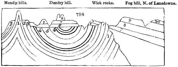
The great coal-series consists of a regular alternation of mineral strata deposited in a great concavity or basin, the sides and bottom of which are composed of transition rocks. This arrangement will be clearly understood by inspecting fig. 794., which represents a section of the coal-field south of Malmsbury.
1, 1, old red sandstone; 2, mountain limestone; 3, millstone grit; 4, 4, coal seams; 5, Pennant, or coarse sandstone; 6, new red sandstone, or red marl; 7, 7, lias; 8, 8, inferior oolite; 9, great oolite; 10, cornbrash and Forest marble.
No. 1., or the old red sandstone, may therefore be regarded as the characteristic lining of the coal basins; but this sandstone rests on transition limestone, and this limestone on grey-wacke. This methodical distribution of the carboniferous series is well exemplified in the coal-basin of the Forest of Dean in the south-west of England, and has been accurately described by Mr. Mushet.
The grey-wacke consists of highly inclined beds of slaty micaceous sandstone, which on the one hand alternates with and passes into a coarse breccia, having grains as large as peas; on the other, into a soft argillaceous slate. The grey-wacke stands bare on the north-eastern border of the Forest, near the southern extremity of the chain of transition limestone, which extends from Stoke Edith, near Hereford, to Flaxley on the Severn. It is traversed by a defile, through which the road from Gloucester to Ross winds. The abruptness of this pass gives it a wild and mountainous character, and affords the best opportunity of examining the varieties of the rock.
The Transition limestone consists in its lower beds of fine-grained, tender, extremely argillaceous slate, known in the district by the name of water-stone, in consequence of the wet soil that is found wherever it appears at the surface. Calcareous matter is interspersed in it but sparingly. Its upper beds consist of shale alternating with extensive beds of stratified limestone. The lowest of the calcareous strata are thin, and alternate with shale. On these repose thicker strata of more compact limestone, often of a dull blue colour. The beds are often dolomitic, which is indicated by straw yellow colour, or dark pink colour, and by the sandy or glimmering aspect of the rock.
The old red sandstone, whose limits are so restricted in other parts of England, here occupies an extensive area. The space which it covers, its great thickness, its high inclination, the abrupt character of the surface over which it prevails, and the consequent display of its strata in many natural sections, present in this strict advantages for studying the formation, which are not to be met with elsewhere in South Britain. In the neighbourhood of Mitchel Dean, the total thickness of this formation, interposed conformably between the transition and mountain limestone, is from 600 to 800 fathoms. The old red sandstone is characterized in its upper portion by the presence of siliceous conglomerate, containing siliceous pebbles, which is applied extensively to the fabrication of millstones near Monmouth, and on the banks of the Wye. This sandstone encircles the Forest with a ring of very elevated ground, whose long and lofty ridges on the eastern frontier overhang the valley of the Severn.
The mountain limestone, or carboniferous, is distinguished from transition limestone, rather by its position than by any very wide difference in its general character or organic remains. According to the measurements of Mr. Mushet, the total thickness of the mountain limestone is about 120 fathoms. The zone of limestone belonging to this coal-basin, is from a furlong to a mile in breadth on the surface of the ground, according as the dip of the strata is more or less rapid. The angle of dip on the northern and western border is often no more than 10°, but on the eastern it frequently amounts to 80°. The calcareous zone that defines the outer circle of the basin, suffers only one short interruption, scarcely three miles in length, where in consequence of a fault the limestone disappears, and the coal-measures are seen in contact with the old red sandstone.
Coal measures.—Their aggregate thickness amounts, according to Mr. Mushet, to about 500 fathoms. 1. The lowest beds, which repose on the mountain limestone, are about 40 fathoms thick, and consist here, as in the Bristol coal-basin, of a red siliceous grit, alternating with conglomerate, used for millstones; and with clay, occasionally used for ochre. 2. These beds are succeeded by a series about 120 fathoms thick, in which a grey gritstone predominates, alternating in the lower part with shale, and containing 6 seams of coal. The grits are of a fissile character, and are quarried extensively for flag-stone, ashlers, and fire-stone. 3. A bed of grit, 25 fathoms thick, quarried for hearth-stone, separates the preceding series from the following, or the 4th, which is about 115 fathoms thick, and consists of from 12 to 14 seams of coal alternating with shale. 5. To this succeeds a straw-coloured sandstone, nearly 100 fathoms thick, forming a high ridge in the interior of the basin. It contains several thin seams of coal, from 6 to 16 inches in thickness. 6. On this reposes a series of about 12 fathoms thick, consisting of 3 seams of coal alternating with shale. 7. This is covered with alternate beds of grit and shale, whose aggregate thickness is about 100 fathoms, occupying a tract in the centre of the basin about 4 miles long, and 2 miles broad. The sandstone No. 5. is probably the equivalent of the Pennant in the preceding figure.
The floor, or pavement, immediately under the coal beds is, almost without exception, a grayish-slate clay, which, when made into bricks, strongly resists the fire. This fire-clay varies in thickness from a fraction of an inch to several fathoms. Clay ironstone is often disseminated through the shale.
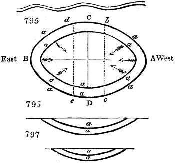
The most complete and simplest form of a coal-field is the entire basin-shape, which we find in some instances without a dislocation. A beautiful example of this is to be seen at Blairengone, in the county of Perth, immediately adjoining the western boundary of Clackmannanshire, as represented in fig. 795., where the outer elliptical line, marked A, B, C, D, represents the crop, outburst, or basset edge of the lower coal, and the inner elliptical line represents the crop or basset edge of the superior coal. Fig. 796. is the longitudinal section of the line A B; and fig. 797. the transverse section of the line C D. All the accompanying coal strata partake of the same form and parallelism. These basins are generally elliptical, sometimes nearly circular, but are often very eccentric, being much greater in length than in breadth; and frequently one side of the basin on the short diameter has a much greater dip than the other, which circumstance throws the trough or lower part of the basin concavity much nearer to the one side than to the other. From this view of one entire basin, it is evident that the dip of the coal strata belonging to it runs in opposite directions, on the opposite sides, and that all the strata regularly crop out, and meet the alluvial cover in every point of the circumferential space, like the edges of a nest of common basins. The waving line marks the river Devon.
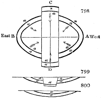
It is from this basin shape that all the other coal-fields are formed, which are segments of a basin produced by slips, dikes, or dislocations of the strata. If the coals (fig. 795.) were dislocated by two slips b c and d e, the slip b c throwing the strata down to the east, and the slip d e throwing them as much up in the same direction, the outcrops of the coals would be found in the form represented in fig. 798., of which fig. 799. is the section in the line A B, and fig. 800. the section in the line C D.
The chief difficulty in exploring a country in search of coal, or one where coal-fields are known to exist, arises from the great thickness of alluvial and other cover, which completely hides the outcrop or basset edge of the strata, called by miners the rock-head; as also the fissures, dikes, and dislocations of the strata, which so entirely change the structure and bearings of coal-fields, and cause often great loss to the mining adventurer. The alluvial cover on the other hand is beneficial, by protecting the seams of the strata from the superficial waters and rains, which would be apt to drown them, if they were naked. In all these figures of coal-basins, the letter a indicates coal.
The absolute shape of the coal-fields in Great Britain has been ascertained with surprising precision. To whatever depth a coal-mine is drained of its water, from that depth it is worked, up to the rise of the water-level line, and each miner continues to advance his room or working-place, till his seam of coal meets the alluvial cover of the outcrop, or is cut off by a dislocation of the strata. In this way the miner travels in succession over every point of his field, and can pourtray its basin-shape most minutely.
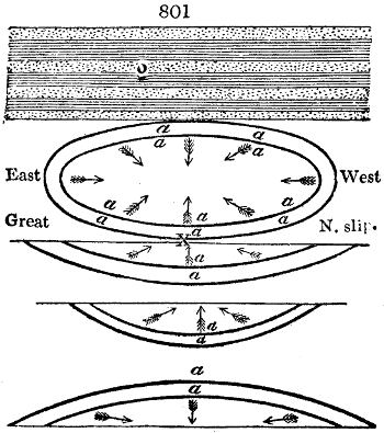
Fig. 801. represents a horizontal plan of the Clackmannanshire coal-field, as if the strata at the outcrop all around were denuded of the alluvial cover. Only two of the concentric beds, or of their edges a, a, are represented, to avoid perplexity. It is to be remembered, however, that all the series of attendant strata lie parallel to the above lines. This plan shows the Ochill mountains, with the north coal-fields, of an oblong elliptical shape, the side of the basin next the mountains being precipitous, as if upheaved by the eruptive trap-rocks; while the south, the east, and the west edges of the basin shelve out at a great distance from the lower part of the concavity or trough, as miners call it. Thus the alternate beds of coal, shale, and sandstone, all nearly concentric in the north coal-field, dip inwards from all sides towards the central area of the trough. The middle coal-field of this district, however, which is formed by the great north slip, is merely the segment of an elliptical basin, where the strata dip in every direction to the middle of the axis marked with the letter X; being the deepest part of the segment. The south coal-field, formed by the great south slip, is likewise the segment of another elliptical basin, similar in all respects to the middle coal-field. Beyond the outcrop of the coals and subordinate strata of the south coal-fields, the counter dip of the strata takes place, producing the mantle-shaped form; whence the coal strata in the Dunmore field, in Stirlingshire, lie in a direction contrary to those of the south coal-field of Clackmannanshire. O, are the Ochill mountains.
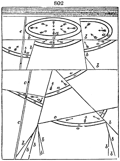
Fig. 802. is intended to represent an extensive district of country, containing a great coal-basin, divided into numerous subordinate coal-fields by these dislocations. The lines marked b are slips, or faults; the broad lines marked c denote dykes: the former dislocate the strata, and change their level, while dykes disjoin the strata with a wall, but do not in general affect their elevation. The two parallel lines marked a, represent two seams of coal, variously heaved up and down by the faults; whereas the dykes are seen to pass through the strata without altering their relative position. In this manner, partial coal-fields are distributed over a wide area of country, in every direction.
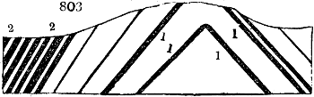
The only exception to this general form of the coal-fields in Great Britain, is the inverted basin shape; but this is rare. A few examples occur in some districts of England, and in the county of Fife; but even in extensive coal-fields, this convex form is but a partial occurrence, or a deviation by local violence from the ordinary basin. Fig. 803 is an instance of a convex coal-field exhibited in Staffordshire, at the Castle-hill, close to the town of Dudley. 1, 1, are limestone strata; 2, 2, are coal. Through this hill, canals have been cut, for working the immense beds of carboniferous limestone. These occur in the lower series of the strata of the coal-field, and therefore at a distance of many miles from the Castle-hill, beyond the outcrop of all the workable coals in the proper basin-shaped part of the field; but by this apparently inverted basin-form, these limestone beds are elevated far above the level of the general surface of the country, and consequently above the level of all the coals. We must regard this seeming inversion as resulting from the approximation of two coal-basins, separated by the basset edges of their mountain limestone repository.
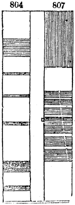
Fig. 804. is a vertical section of the Dudley coal-basin, the upper coal-bed of which has the astonishing thickness of 30 feet; and this mass extends 7 miles in length, and 4 in breadth. Coal-seams 5 or 6 feet thick, are called thin in that district.
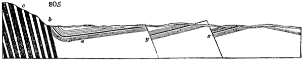
Fig. 805. is a very interesting section of the main coal-basin of Clackmannanshire, as given by Mr. Bald in the Wernerian Society’s Memoirs, vol. iii. Here we see it broken into three subordinate coal-fields, formed by two great faults or dislocations of the strata; but independently of these fractures across the whole series, the strata continue quite regular in their respective alternations, and preserve nearly unchanged their angle of inclination to the horizon. The section shows the south coal-field dipping northerly, till it is cut across by the great south slip x, which dislocates the coal and the parallel strata to the enormous extent of 1230 feet, by which all the coals have been thrown up, not simply to the day, but are not found again till we advance nearly a mile northward, on the line of the dip, where the identical seams of coal, shale, &c. are observed once more with their regular inclination. These coals of the middle area, dip regularly northward till interrupted by the great north slip y, which dislocates the strata, and throws them up 700 feet; that is to say, a line prolonged in the direction of any one well-known seam, will run 700 feet above the line of the same seam as it emerges after the middle slip. Immediately adjoining the north slip, the coals and coal-field resume their course, and dip regularly northward, running through a longer range than either of the other two members of the basin, till they arrive at the valley of the Devon, at the foot of the Ochill mountains, where they form a concave curvature, or trough, a, and thence rise rapidly in an almost vertical direction at b. Here the coals, with all their associate strata, assume conformity and parallelism with the face of the sienitic-greenstone strata of the Ochill mountains c; being raised to the high angle of 73 degrees with the horizon. The coal-seams thus upheaved, are called edge-metals by the miners.

In this remarkable coal-field, which has been accurately explored by pitting and boring to the depth of 703 feet, there are no fewer than 142 beds, or distinct strata of coal, shale, and sandstone, &c., variously alternating, an idea of which may be had by inspecting fig. 806. Among these are 24 beds of coal, which would constitute an aggregate thickness of 59 feet 4 inches; the thinnest seam of coal being 2 inches, and the thickest 9 feet. The strata of this section contain numerous varieties of sandstone, slate-clay, bituminous shale, indurated clay, or fire-clay, and clay ironstone. Neither trap-rock nor limestone is found in connexion with the workable coals; but an immense bed of greenstone, named Abbey Craig, occurs in the western boundary of Clackmannanshire, under which lie regular strata of slate-clay, sandstone, thin beds of limestone, and large spheroidal masses of clay ironstone, with a mixture of lime.
“With regard to slips in coal fields,” says Mr. Bald, “we find that there is a general law connected with them as to the position of the dislocated strata, which is this:—When a slip is met with in the course of working the mines—if when looking to it, the vertical line of the slip or fissure, it forms an acute angle with the line of the pavement upon which the observer stands, we are certain that the strata are dislocated downwards upon the other side of the fissure. On the contrary, if the angle formed by the two lines above mentioned is obtuse, we are certain that the strata are dislocated or thrown upwards upon the other side of the fissure. When the angle is 90°, or a right angle, it is altogether uncertain whether the dislocation throws up or down on the opposite side of the slip. When dikes intercept the strata, they generally only separate the strata the width of the dike, without any dislocation, either up or down; so that if a coal is intercepted by a dike, it is found again by running a mine directly forward, corresponding to the angle or inclination of the coal with the horizon.”—Wernerian Society’s Memoirs, vol. iii. p. 133.[40]
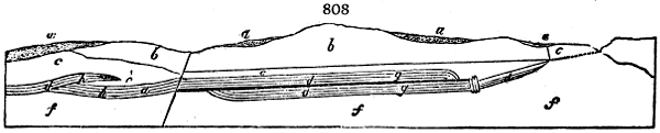
a. Alluvial cover.
b. Bed of trap or greenstone.
c. Alternating coal strata.
d. Coal-seams.
e. Position of greenstone, not ascertained.
f. Strata in which no coals have been found.
g. The overlapped coal.
h. The double coal.
The Johnstone coal-field, in Renfrewshire, is both singular and interesting. The upper stratum of rock is a mass of compact greenstone or trap, above 100 feet in thickness, not at all in a conformable position with the coal strata, but overlying; next there is a few fathoms of soft sandstone and slate-clay, alternating, and uncommonly soft. Beneath these beds, there are no fewer than ten seams of coal, lying on each other, with a few divisions of dark indurated clay. These coal-seams have an aggregate thickness of no less than 100 feet; a mass of combustible matter, in the form of coal, unparalleled for its accumulation in so narrow a space. The greater part of this field contains only 5 beds of coal; but at the place where the section shown in fig. 807. is taken, these 5 coals seem to have been overlapped or made to slide over each other by violence. This structure is represented in fig. 808., which is a section of the Quarrelton coal in the Johnstone field, showing the overlapped coal and the double coal, with the thick bed of greenstone, overlying the coal-field.
Before proceeding to examine the modes of working coal, I shall introduce here a description of the two principal species of this mineral.
1. Cubical coal.—It is black, shining, compact, moderately hard, but easily frangible. When extracted in the mine, it comes out in rectangular masses, of which the smaller fragments are cubical. The lamellæ (reed of the coal) are always parallel to the bed or plane on which the coal rests; a fact which holds generally with this substance. There are two varieties of cubical coal; the open-burning and the caking. The latter, however small its fragments may be, is quite available for fuel, in consequence of its agglutinating into a mass at a moderate heat, by the abundance of its bitumen. This kind is the true smithy or forge-coal, because it readily forms itself into a vault round the blast of the bellows, which serves for a cupola in concentrating the heat on objects thrust into the cavity.
The open-burning cubical coals are known by several local names; the rough coal or clod coal, from the large masses in which they may be had; and the cherry coal, from the cheerful blaze with which they spontaneously burn; whereas the caking coals, such as most of the Newcastle qualities, require to be frequently poked in the grate. Its specific gravity varies from 1·25 to 1·4.
2. Slate or splint coal.—This is dull-black, very compact, much harder, and more difficultly frangible than the preceding. It is readily fissile, like slate, but powerfully resists the cross fracture, which is conchoidal. Specific gravity from 1·26 to 1·40. In working, it separates in large quadrangular sharp-edged masses. It burns without caking, produces much flame and smoke, unless judiciously supplied with air, and leaves frequently a considerable bulk of white ashes. It is the best fuel for distilleries and all large grates, as it makes an open fire, and does not clog up the bars with glassy scoriæ. I found good splint coal of the Glasgow field to have a specific gravity of 1·266, and to consist of—carbon, 70·9; hydrogen, 4·3; oxygen, 24·8.
3. Cannel coal.—Colour between velvet and grayish-black; lustre resinous; fracture even; fragments trapezoidal; hard as splint coal; spec. grav. 1·23 to 1·28. In working, it is detached in four-sided columnar masses, often breaks conchoidal, like pitch, kindles very readily, and burns with a bright white projective flame, like the wick of a candle, whence its name. It occurs most abundantly in the coal-field of Wigan, in Lancashire, in a bed 4 feet thick; and there is a good deal of it in the Clydesdale coal-field, of which it forms the lowest seam that is worked. It produces very little dust in the mine, and hardly soils the fingers with carbonaceous matter. Cannel coal from Woodhall, near Glasgow, spec. grav. 1·228, consists by my analysis of—carbon, 72·22; hydrogen, 3·93; oxygen, 21·05; with a little azote (about 2·8 in 100 parts). This coal has been found to afford, in the Scotch gas-works, a very rich-burning gas. The azote is there converted into ammonia, of which a considerable quantity is distilled over into the tar-pit.
4. Glance coal.—This species has an iron-black colour, with an occasional iridescence, like that of tempered steel; lustre in general splendent, shining, and imperfect metallic; does not soil; easily frangible; fracture flat conchoidal; fragments sharp-edged. It burns without flame or smell, except when it is sulphureous; and it leaves a white-coloured ash. It produces no soot, and seems, indeed, to be merely carbon, or coal deprived of its volatile matter or bitumen, and converted into coke by subterranean calcination, frequently from contact with whin-dikes. Glance coal abounds in Ireland, under the name of Kilkenny coal; in Scotland it is called blind coal, from its burning without flame or smoke; and in Wales, it is the malting or stone coal. It contains from 90 to 97 per cent. of carbon. Specific gravity from 1·3 to 1·5; increasing with the proportion of earthy impurities.
The dislocations and obstructions found in coal-fields, which render the search for coal so difficult, and their mining so laborious and uncertain, are the following:—
1. Dikes. 2. Slips or Faults. 3. Hitches. 4. Troubles.
The first three infer dislocation of the strata; the fourth changes in the bed of coal itself.
1. A dike is a wall of extraneous matter, which divides all the beds in a coal-field.
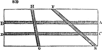
Dikes extend not only in one line of bearing through coal-fields for many miles, but run sometimes in different directions, and have often irregular bendings, but no sharp angular turns. When from a few feet to a few fathoms in thickness, they occur sometimes in numbers within a small area of a coal basin, running in various directions, and even crossing each other. Fig. 809. represents a ground plan of a coal-field, intersected with greenstone dikes. A B and C D are two dikes standing parallel to each other; E F and G H are cross or oblique dikes, which divide both the coal strata and the primary dikes A B and C D.
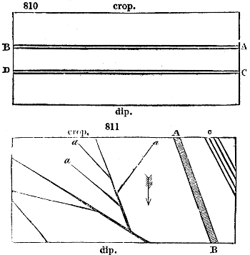
2. Slips or faults run in straight lines through coal-measures, and at every angle of incidence to each other. Fig. 810. represents a ground plan of a coal-field, with two slips A B and C D in the line of bearing of the planes of the strata, which throw them down to the outcrop. This is the simplest form of a slip. Fig. 811. exhibits part of a coal-field intersected with slips, like a cracked sheet of ice. Here A B is a dike; while the narrow lines show faults of every kind, producing dislocations varying in amount of slip from a few feet to a great many fathoms. The faults at the points a, a, a vanish; and the lines at c denote four small partial slips called hitches.
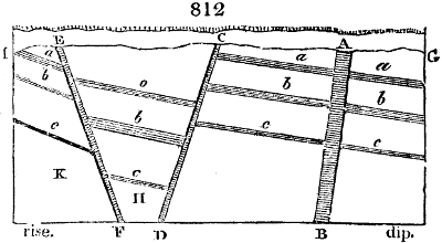
The effects of slips and dikes on the coal strata appear more prominently when viewed in a vertical section, than in a ground plan, where they seem to be merely walls, veins, and lines of demarcation. Fig. 812. is a vertical section of a coal-field, from dip to rise, showing three strata of coal a, b, c. A B represents a dike at right angles to the plane of the coal-beds. This rectangular wall merely separates the coal-measures, affecting their line of rise; but further to the rise, the oblique dike C D interrupts the coals a, b, c, and not only disjoins them, but throws them and their concomitant strata greatly lower down; but still, with this depression, the strata retain their parallelism and general slope. Nearer to the outcrop, another dike E, F, interrupts the coals a, b, c, not merely breaking the continuity of the planes, but throwing them moderately up, so as to produce a steeper inclination, as shown in the figure. It sometimes happens that the coals in the compartment H, betwixt the dikes C and E, may lie nearly horizontal, and the effect of the dike E, F, is then to throw out the coals altogether, leaving no vestige of them in the compartment K. “Such,” says Mr. Bald, from whom these illustrations are borrowed, “are the most prominent changes in the strata, as to their line of direction, produced by dikes; but of these changes there are various modifications.”
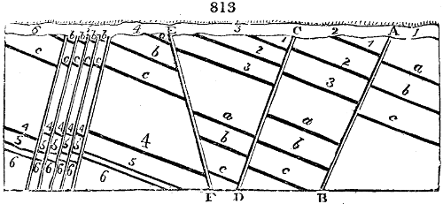
The effect of slips on the strata is also represented in the vertical section, fig. 813., where a, b, c are coals with their associated strata. A, B, is an intersecting slip, which throws all the coals of the first compartment much lower, as is observable in the second, No. 2.; and from the amount of the slip, it brings in other coal-seams, marked 1, 2, 3, not in the compartment No. 1. C, D, is a slip producing a similar result, but not of the same magnitude. E, F, represents a slip across the strata, reverse in direction to the former; the effect of which is to throw up the coals, as shown in the area No. 4. Such a slip occasionally brings into play seams seated under those marked a, b, c, as seen at 4, 5, 6; and it may happen that the coal marked 4 lies in the prolongation of a well-known seam, as c, in the compartment No. 3., when the case becomes puzzling to the miner. In addition to the above varieties, a number of slips or hitches are often seen near one another, as in the area marked No. 5., where the individual displacements are inconsiderable, but the aggregate dislocation may be great, in reference to the seams of the 6th compartment.
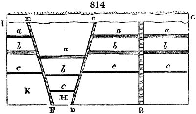
The results of dikes and slips on a horizontal portion of a field are exemplified in fig. 814. Where the coal-measures are horizontal, and the faults run at a greater angle than 45° to the line of bearing, they are termed dip and rise faults, as A B, C D, E F.
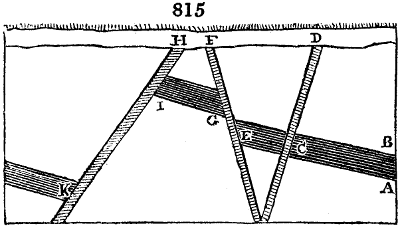
Coal viewers or engineers regard the dislocations now described as being subject in one respect to a general law, which may be thus explained:—Let fig. 815. be a portion of a coal-measure; A, being the pavement and B the roof of the coal-seam. If, in pursuing the stratum at C, a dike D occurs, standing at right angles with the pavement, they conclude that the dike is merely a partition-wall between the beds by its own thickness, leaving the coal-seam underanged on either side; but if a dike F forms, as at E, an obtuse angle with the pavement, they conclude that the dike is not a simple partition between the strata, but has thrown up the several seams into the predicament shown at G. Finally, should a dike H make at I an acute angle with the pavement, they conclude that the dike has thrown down the coal-measures into the position of K.
The same important law holds with slips, as I formerly stated; only when they form right angles with the pavement, the case is ambiguous; that is, the strata may be dislocated either upwards or downwards.
Dikes and faults are denominated upthrow or downthrow, according to the position they are met with in working the mine. Thus, in fig. 812., if the miner is advancing to the rise, the dike A, B obviously does not change the direction; but C, D is a downthrow dike of a certain number of fathoms towards the rise of the basin, and E, F is an upthrow dike likewise towards the rise. On the other hand, when the dikes are met with by the miner in working from the rise to the dip, the names of the above dikes would be reversed; for what is an upthrow in the first case, becomes a downthrow in the second, relative to the mining operations.
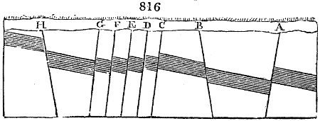
3. We have seen that hitches are small and partial slips, where the dislocation does not exceed the thickness of the coal-seam; and they are correctly enough called steps by the miner. Fig. 816. represents the operation of the hitches A, B, C, D, E, F, G, H, on the coal-measures. Though observed in one or two seams of a field, they may not appear in the rest, as is the case with dikes and faults.
4. Troubles in coal-fields are of various kinds.
1. Irregular layers of sandstone, appearing in the middle of the coal-seam, and gradually increasing in thickness till they separate the coal into two distinct seams, too thin to continue workable.
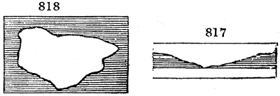
2. Nips, occasioned by the gradual approximation of the roof and pavement, till not a vestige of coal is left between them; the softer shale disappearing also at the same time. Figs. 817. and 818. represent this accident, which is fortunately rare; the first being a vertical, and the second a horizontal view.
3. Shaken coal. It resembles the rubbish of an old waste, being a confused heap of coal-dust, mixed with small pieces of cubical coal, so soft that it can frequently be dug with the spade. This shattering is analogous to that observed occasionally in the flint nodules of the chalk formation; and seems like the effect of some electric tremor of the strata.
In searching for coal in any country, its concomitant rocks ought to be looked for, especially the carboniferous or mountain limestone, known by its organic fossils; (see Ure’s Geology, p. 175, and corresponding plate of fossils;) likewise the outcrop of the millstone grit, and the newer red sandstone, among some rifts or façades of which, seams of coal may be discerned. But no assurance of coal can be had without boring or pitting.
Skill in boring judiciously for coal, distinguishes the genuine miner from the empirical adventurer, who, ignorant of the general structure of coal-basins, expends labour, time, and money at random, and usually to no purpose; missing the proper coal-field, and leading his employer to sink a shaft where no productive seams can be had. A skilful viewer, therefore, should always direct the boring operations, especially in an unexplored country.
The boring rods should be made of the best and most tenacious Swedish iron; in area, about an inch and a quarter square. Each rod is usually 3 feet long, terminating in a male screw at one end, and a female screw at the other. The boring chisels are commonly 18 inches long, and from 2 inches and a half to 3 inches and a quarter at their cutting edge, which must be tipped with good steel. The chisel is screwed to an intermediate 18-inch rod, called the double box-rod, forming together a rod 3 feet long. There are, moreover, three short rods, a foot, 18 inches, and 2 feet long each, which may be screwed, as occasion requires, to the brace-head, to make the height above the mouth of the bore convenient for the hands of the men in working the rods. Hence the series of rods becomes a scale of measurement for noting the depth of the bore, and keeping a journal of the strata that are perforated. The brace-head rod, also 18 inches long, has two large eyes or rings at its top, set at right angles to each other, through which arms of wood are fixed for the men to lift and turn the rods by, in the boring process.
When the bore is intended to penetrate but a few fathoms, the whole work may be performed directly by the hands; but when the bore is to be of considerable depth, a lofty triangle of wood is set above the bore-hole, with a pulley depending at its summit angle, for conducting the rope to the barrel of a windlass or wheel and axle, secured to the ground with heavy stones. The loose end of the rope is connected to the rods by an oval iron ring, called a runner; and by this mechanism they may be raised and let fall in the boring; or the same effect may be more simply produced by substituting for the wheel and axle, a number of ropes attached to the rod-rope, each of which may be pulled by a man, as in raising the ram of the pile-engine.
In the Newcastle coal district there are professional master-borers, who undertake to search for coal, and furnish an accurate register of the strata perforated. The average price of boring in England or Scotland, where no uncommon difficulties occur, is six shillings for each of the first five fathoms, twice 6 shillings for each of the second five fathoms, thrice 6 shillings for each of the third five fathoms, and so on; hence the series will be—
1st five fathoms 6s. each £1 10
2nd five fathoms 12s. — 3 0
3rd five fathoms 18s. — 4 10
4th five fathoms 24s. — 6 0
20 fathoms of bore £15 0
Thus the price increases equably with the depth and labour of the bore, and the undertaker usually upholds his rods. There are peculiar cases, however, in which the expense greatly exceeds the above rate.
The boring tools are represented in the following figures:—
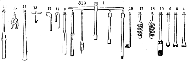
Fig. 819.
1. The brace-head.
2. The common rod.
3. The double-box rod; intermediate piece.
4. The common chisel.
5. The indented chisel.
6. Another of the same.
7. The cross-mouthed chisel.
8. The wimble.
9. The sludger, for bringing up the mud.
10. The rounder.
11. The key for supporting the train of rods at the bore-mouth.
12. The key for screwing together and asunder the rods.
13. The topit, or top-piece.
14. The beché, for catching the rod when it breaks in the bore.
15. The runner, for taking hold of the topit.
16. The tongued chisel.
17. The right-handed worm screw.
18. The left-handed do.
19. The finger-grip or catch.
We shall now explain the manner of conducting a series of bores in searching ground for coal.
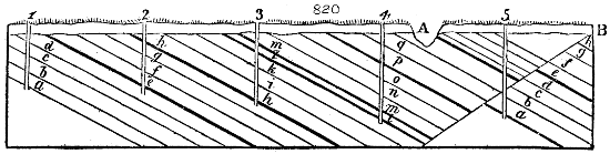
Fig. 820. represents a district of country in which a regular survey has proved the existence and general distribution of coal strata, with a dip to the south, as here shown. In this case, a convenient spot should be pitched upon in the north part of the district, so that the successive bores put down may advance in the line of the dip. The first bore may therefore be made at No. 1., to the depth of sixty yards. In the progress of this perforation, many diversities and alternations of strata will be probably passed through, as we see in the sections of the strata; each of which, as to quality and thickness, is noted in the journal, and specimens are preserved. This bore is seen to penetrate the strata d, c, b, a, without encountering any coal. Now, suppose that the dip of the strata be one yard in ten, the question is, at what distance from bore No. 1. in a south direction, will a second bore of 60 yards strike the first stratum d, of the preceding? The rule obviously is, to multiply the depth of the bore by the dip, that is, 60 by 10, and the product 600 gives the distance required; for, by the rule of three, if 1 yard of depression corresponds to 10 in horizontal length, 60 yards of depression will correspond to 600 in length. Hence the bores marked 1, 2, 3, 4, and 5, are successively distributed as in the figure, the spot where the first is let down being regarded as the point of level to which the summits of all the succeeding bores are referred. Should the top of No. 2. bore be 10 yards higher or lower than the top of No. 1., allowance must be made for this difference in the operation; and hence a surface level survey is requisite. Sometimes ravines cut down the strata, and advantage should be taken of them, when they are considerable.
In No. 2. a coal is seen to occur near the surface, and another at the bottom of the bore; the latter seam resting on the first stratum d, that occurred in bore No. 1.; and No. 2. perforation must be continued a little farther, till it has certainly descended to the stratum d. Thus these two bores have, together, proved the beds to the depth of 120 yards.
No. 3. bore being placed according to the preceding rule, will pass through two coal-seams near the surface, and after reaching to nearly its depth of 60 yards, it will touch the stratum h, which is the upper stratum of bore No. 2.; but since a seam of coal was detected in No. 2., under the stratum h, the proof is confirmed by running the borer down through that coal. The field has now been probed to the depth of 180 yards. The fourth bore is next proceeded with, till the two coal-seams met in No. 3. have been penetrated; when a depth of 240 yards has been explored. Hence No. 4. bore could not reach the lower stratum a, unless it were sunk 240 yards.
The fifth bore (No. 5.) being sunk in like manner, a new coal-seam occurs within a few yards of the surface; but after sinking to the depth at which the coal at the top of the fourth bore was found, an entirely different order of strata will occur. In this dilemma, the bore should be pushed 10 or 20 yards deeper than the 60 yards, to ascertain the alternations of the new range of superposition. It may happen that no coals of any value shall be found, as the figure indicates, in consequence of a slip or dislocation of the strata at B, which has thrown up all the coals registered in the former borings, to such an extent that the strata b, a, of the first bore present themselves immediately on perforating the slip, instead of lying at the depth of 300 yards (5 × 60), as they would have done, had no dislocation intervened. Some coal-fields, indeed, are so intersected with slips as to bewilder the most experienced miner, which will particularly happen when a lower coal is thrown upon one side of a slip, directly opposite to an upper coal situated on the other side of it; so that if the two seams be of the same thickness, erroneous conclusions are almost inevitable.
When a line of bores is to be conducted from the dip of the strata towards their outcrop, they should be placed a few yards nearer each other than the rule prescribes, lest the strata last passed through be overstepped, so that they may disappear from the register, and a valuable coal-seam may thereby escape notice. In fact, each successive bore should be so set down, that the first of the strata perforated should be the last passed through in the preceding bore; as is exemplified by viewing the bores in the retrograde direction, Nos. 4. 3. and 2. But if the bore No. 2. had gone no deeper than f, and the bore No. 1. been as represented, then the stratum e, with its immediately subjacent coal, would have been overstepped, since none of the bores would have touched it; and they would have remained unnoticed in the journal, and unknown.
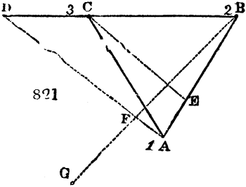
When the line of dip, and consequently the line of bearing which is at right angles to it, are unknown, they are sought for by making three bores in the following position.—Let fig. 821. be a horizontal diagram, in which the place of a bore, No. 1., is shown, which reaches a coal-seam at the depth of 50 yards; bore No. 2. may be made at B, 300 yards from the former; and bore No. 3. at C, equidistant from Nos. 1. and 2., so that the bores are sunk at the three angles of an equilateral triangle. If the coal occur in No. 2. at the depth of 30 yards, and in No. 3. of 44 yards, it is manifest that none of the lines A B, B C, or C A is in the line of level, which for short distances may be taken for the line of bearing, with coal-seams of moderate dip. But since No. 1. is the deepest of the three bores, and No. 3. next in depth, the line A C joining them must be nearer the line of level, than either of the lines A B or B C. The question is, therefore, at what distance on the prolonged line B C is the point for sinking a bore which would reach the coal at the same depth as No. 1., namely 50 yards. This problem is solved by the following rule of proportion: as 14 yards (the difference of depth between bores 2. and 3.) is to 300 yards (the distance between them), so is 20 (the difference of depth betwixt 1. and 2.) to a fourth proportion, or x = 428 yards, 1 foot, and 8 inches. Now, this distance, measured from No. 2., reaches to the point D on the prolonged line B C, under which point D the coal will be found at a depth of 50 yards, the same as under A. Hence the line A D is the true level line of the coal-field; and a line B F G drawn at right angles to it, is the true dip-line of the plane which leads to the outcrop. In the present example the dip is 1 yard in 141⁄2; or 1 in 141⁄2, to adopt the judicious language of the miner; or the sine is 1 to a radius of 141⁄2, measured along the line from B to F. By this theorem for finding the lines of dip and level, the most eligible spot in a coal-field for sinking a shaft may be ascertained.
Suppose the distance from B to G in the line of dip to be 455 yards; then, since every 141⁄2 gives a yard of depression, 455 will give 30 yards, which added to 30 yards, the depth of the bore at B, will make 60 yards for the depth of the same coal-seam at G. Since any line drawn at right angles to the line of level A D is the line of dip, so any line drawn parallel to A D is a level line. Hence, if from C the line C E be drawn parallel to D A, the coal-seam at the points E and C will be found in the same horizontal plane, or 44 yards beneath the surface level, over these two points. The point E level with C may also be found by this proportion: as 20 yards (the difference in depth of the bores under B and A) is to 300 yards (the distance between them), so is 14 yards (the difference of depth under B and C) to 210 yards, or the distance from B to E.
As boring for coal is necessarily carried on in a line perpendicular to the horizon, and as coal seams lie at every angle of inclination to it, the thickness of the seam as given obliquely by the borer, is always greater than the direct thickness of the coal; and hence the length of that line must be multiplied by the cosine of the angle of dip, in order to find the true power of the seam.
Of fitting or winning a coal-field.—In sinking a shaft for working coal, the great obstacle to be encountered, is water, particularly in the first opening of a field, which proceeds from the surface of the adjacent country; for every coal-stratum, however deep it may lie in one part of the basin, always rises till it meets the alluvial cover, or crops out, unless it be met by a slip or dike. When the basset-edge of the strata is covered with gravel or sand, any body or stream of water will readily percolate downwards through it, and fill up the porous interstices between the coal-measures, till arrested by the face of a slip, which acts as a valve or flood-gate, and confines the water to one compartment of the basin, which may, however, be of considerable area, and require a great power of drainage.
In reference to water, coal-fields are divided into two kinds; 1., level free coal; 2., coal not level free. In the practice of mining, if a coal-field, or portion of it, is so situated above the surface of the ocean that a level can be carried from that plane till it intersects the coal, all the coal above the plane of intersection is said to be level free; but if a coal-field, though placed above the surface of the ocean, cannot, on account of the expense, be drained by a level or gallery, but by mechanical power, such a coal-field is said to be not level free.
Besides these general levels of drainage, there are subsidiary levels, called off-takes or drifts, which discharge the water of a mine, not at the mouth of the pit, but at some depth beneath the surface, where, from the form of the country, it may be run off level free. From 20 to 30 fathoms off-take is an object of considerable economy in pumping; but even less is often had recourse to; and when judiciously contrived, may serve to intercept much of the crop water, and prevent it from getting down to the dip part of the coal, where it would become a heavy load on a hydraulic engine.
Day levels were an object of primary importance with the early miners, who had not the gigantic pumping power of the steam-engine at their command. Levels ought to be no less than 4 feet wide, and from 5 feet and a half to 6 feet high: which is large enough for carrying off water, and admitting workmen to make repairs and clear out depositions. When a day-level, however, is to serve the double purpose of drainage and an outlet for coals, it should be nearly 5 feet wide, and have its bottom gutter covered over. In other instances a level not only carries off the water from the colliery, but is converted into a canal for bearing boats loaded with coals for the market. Some subterranean canals are nine feet wide, and twelve feet high, with 5 feet depth of water.
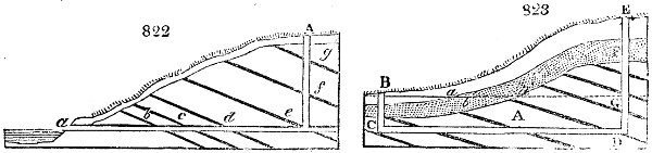
If in the progress of driving a level, workable coals are intersected before reaching the seam which is the main object of the mining adventure, an air-pit may be sunk, of such dimension as to serve for raising the coals. These air-pits do not in general exceed 7 foot in diameter; and they ought to be always cylindrical. Fig. 822. represents a coal-field where the winning is made by a day-level; a is the mouth of the gallery on a level with the sea; b, c, d, e, are intersected coal-seams, to be drained by the gallery. But the coals beneath this level must obviously be drained by pumping. A represents a coal-pit sunk on the coal e; and if the gallery be pushed forward, the coal-seams f, g, and any others which lie in that direction, will also be drained, and then worked by the pit A. The chief obstacle to the execution of day-levels, is presented by quicksands in the alluvial cover, near the entrance of the gallery. The best expedient to be adopted amid this difficulty is the following:—Fig. 823. represents the strata of a coal-field A, with the alluvial earth a, b, containing the bed of quicksand b. The lower part, from which the gallery is required to be carried, is shown by the line B d. But the quicksand makes it impossible to push forward this day-level directly. The pit B C must therefore be sunk through the quicksand by means of tubbing (to be presently described), and when the pit has descended a few yards into the rock, the gallery or drift may then be pushed forward to the point D, when the shaft E D is put down, after it has been ascertained by boring that the rock-head or bottom of the quicksand at F is a few yards higher than the mouth of the small pit B. During this operation, all the water and mine-stuff, are drawn off by the pit B; but whenever the shaft E D is brought into communication with the gallery, the water is allowed to fill it from C to D, and rise up both shafts till it overflows at the orifice B. From the surface of the water in the deep shaft at G, a gallery is begun of the common dimensions, and pushed onwards till the coal sought after is intersected. In this way no drainage level is lost. This kind of drainage gallery, in the form of an inverted syphon, is called a drowned or a blind level.
When a coal-basin is so situated that it cannot be rendered level free, the winning must be made by the aid of machinery. The engines at present employed in the drainage of coal-mines are:—
1. The water-wheel, and water-pressure engine.
2. The atmospheric steam-engine of Newcomen.
3. The steam-engine, both atmospheric and double stroke, of Watt.
4. The expansion steam-engine of Woolf.
5. The high-pressure steam-engine, without a condenser.
The depth at which the coal is to be won, or to be drained of moisture, regulates the power of the engine to be applied, taking into account the probable quantity of water which may be found, a circumstance which governs the diameter of the working barrels of the pumps. Experience has proved, that in opening collieries, even in new fields, the water may generally be drawn off by pumps of from 10 to 15 inches diameter; excepting where the strata are connected with rivers, sand-beds filled with water, or marsh-lands. As feeders of water from rivers or sand-beds may be hindered from descending coal-pits, the growth proceeding from these sources need not be taken into account; and it is observed, in sinking shafts, that though the influx which cannot be cut off from the mine, may be at first very great, even beyond the power of the engine for a little while, yet as this excessive flow of water is frequently derived from the drainage of fissures, it eventually becomes manageable. An engine working the pumps for 8 or 10 hours out of the 24, is reckoned adequate to the winning of a new colliery, which reaps no advantage from neighbouring hydraulic powers. In the course of years, however, many water-logged fissures come to be cut by the workings, and the coal seams get excavated towards the outcrop, so that a constant increase of water ensues, and thus a colliery which has been long in operation, frequently becomes heavily loaded with water, and requires the action of its hydraulic machinery both night and day.
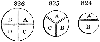
Of Engine Pits.—In every winning of coal, the shape of the engine-pit deserves much consideration. For shafts of moderate depth, many forms are in use; as circular, oval, square, octagonal, oblong rectangular, and oblong elliptical. In pits of inconsiderable depth, and where the earthy cover is firm and dry, any shape deemed most convenient may be preferred; but in all deep shafts, no shape but the circular should be admitted. Indeed, when a water-run requires to be stopped by tubbing or cribbing, the circular is the only shape which presents a uniform resistance in every point to the equable circumambient pressure. The elliptical form is the next best, when it deviates little from the circle; but even it has almost always given way to a considerable pressure of water. The circular shape has the advantage, moreover, of strengthening the shaft walls, and is less likely to suffer injury than other figures, should any failure of the pillars left in working out the coal cause the shaft to be shaken by subsidence of the strata. The smallest engine-pit should be ten feet in diameter, to admit of the pumps being placed in the lesser segment, and the coals to be raised in the larger one, as shown in fig. 824., which is called a double pit. If much work is contemplated in drawing coals, particularly if their masses be large, it would be advantageous to make the pit more than 10 feet wide. When the area of a shaft is to be divided into three compartments, one for the engine pumps, and two for raising coals, as in fig. 825., which is denominated a triple pit, it should be 12 feet in diameter. If it is to be divided into four compartments, and made a quadrant shaft, as in fig. 826., with one space for the pumps, and three for ventilation and coal-drawing, the total circle should be 15 feet in diameter. These dimensions are, however, governed by local circumstances, and by the proposed daily discharge of coals.
The shaft, as it passes through the earthy cover, should be securely faced with masonry of jointed ashler, having its joints accurately bevelled to the centre of the circle. Specific directions for building the successive masses of masonry, on a series of rings or cribs of oak or elm, are given by Mr. Bald, article Mine, Brewster’s Encyclopædia, p. 336.
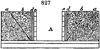
When the alluvial cover is a soft mud, recourse must be had to the operation of tubbing. A circular tub, of the requisite diameter, is made of planks from 2 to 3 inches thick, with the joints bevelled by the radius of the shaft, inside of which are cribs of hard wood, placed from 2 to 4 feet asunder, as circumstances may require. These cribs are constructed of the best heart of oak, sawn out of the natural curvature of the wood, adapted to the radius, in segments from 4 to 6 feet long, from 8 to 10 inches in the bed, and 5 or 6 inches thick. The length of the tub is from 9 to 12 feet, if the layer of mud have that thickness; but a succession of such tubs must be set on each other, provided the body of mud be thicker. The first tub must have its lower edge thinned all round, and shod with sharp iron. If the pit be previously secured to a certain depth, the tub is made to pass within the cradling, and is lowered down with tackles till it rests fair among the soft alluvium. It is then loaded with iron weights at top, to cause it to sink down progressively as the mud is removed from its interior. Should a single tub not reach the solid rock (sandstone or basalt), then another of like construction is set on, and the gravitating force is transferred to the top. Fig. 827. represents a bed of quicksand resting on a bed of impervious clay, that immediately covers the rock. A is the finished shaft; a a, the quicksand; b b, the excavation necessarily sloping much outwards; c c, the lining of masonry; d d, the moating or puddle of clay, hard rammed in behind the stone-work, to render the latter water-tight. In this case, the quicksand, being thin in body, has been kept under for a short period, by the hands of many men scooping it rapidly away as it filled in. But the most effectual method of passing through beds of quicksand, is by means of cast-iron cylinders; called, therefore, cast-iron tubbing. When the pit has a small diameter, these tubs are made about 4 feet high, with strong flanges, and bolt holes inside of the cylinder, and a counterfort ring at the neck of the flange, with brackets: the first tub, however, has no flange at its lower edge, but is rounded to facilitate its descent through the mud. Should the pit be of large diameter, then the cylinders must be cast in segments of 3, 4, or more pieces, joined together with inside vertical flanges, well jointed with oakum and white lead. When the sand-bed is thick, eighty feet, for instance, it is customary to divide that length into three sets of cylinders, each thirty feet long, and so sized as to slide within each other, like the eye tubes of a telescope. These cylinders are pressed down by heavy weights, taking care to keep the lower part always further down than the top of the quicksand, where the men are at work with their shovels, and where the bottom of the pumps hangs for withdrawing the surface water. This is an improvement adopted of late years in the Newcastle district with remarkable success.
The engine pit being secured, the process of sinking through the rock is ready to be commenced, as soon as the divisions of the pit formed of carpentry, called brattices, are made. In common practice, and where great tightness of jointing is not required, for ventilating inflammable air, bars of wood, called buntons, about 6 inches thick, and 9 deep, are fixed in a horizontal position across the pit, at distances from each other of 10, 20, or 30 feet, according to circumstances. Being all ranged in the same vertical plane, deals an inch and a half thick are nailed to them, with their joints perfectly close; one half of the breadth of a bunton being covered by the ends of the deals. In deep pits, where the ventilation is to be conducted through the brattice, the side of the buntons next the pumps is covered with deals in the same way, and the joints are rendered secure by being caulked with oakum. Fillets of wood are also fixed all the way down on each side of the brattice, constituting what is called a double pit.
When a shaft is to have 3 compartments, it requires more care to form the brattice, as none of the buntons stretch across the whole space, but merely meet near the middle, and join at certain angles with each other. As the buntons must therefore sustain each other, on the principle of the arch, they are not laid in a horizontal plane, but have a rise from the sides towards the place of junction of 8 or 9 inches, and are bound together by a three-tongued iron strap. Fillets of wood are carried down the whole depth, not merely at the joinings of the brattice with the sides of the pit, but also at their central place of union; while wooden pillars connect the centre of each set of buntons with those above and below. Thus the carpentry work acquires sufficient strength and stiffness.
In quadrant shafts the buntons cross each other towards the middle of the pit, and are generally let into each other about an inch, instead of being half-checked. Fig. 824. is a double shaft: A, the pump pit; B, the pit for raising coal. Fig. 825. is a triple shaft; in which A is the pump compartment; B and C are coal pits. Fig. 826. is a quadrant shaft: A, the pump pit; B, pit of ventilation or upcast for the smoke; C and D, pits for raising coals.
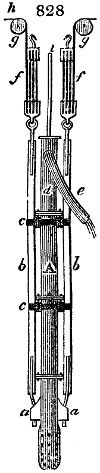
A depth of 75 fathoms is fully the average of engine pits in Great Britain. In practice, it embraces three sets of pumps. Whenever the shaft is sunk so low that the engine is needed to remove the water, the first set of pumps may be let down by the method represented in fig. 828.; where A is the pump; a a, strong ears through which pass the iron rods connected with the spears b b; c c are the lashings; d, the hoggar pump; e, the hoggar; f f, the tackles; g g, the single pulleys; h h, the tackle fold leading to the capstans; and i, the pump-spears. By this mechanical arrangement the pumps are sunk in the most gradual manner, and of their own accord, so to speak, as the pit descends. To the arms of the capstans, sledges are fastened with ropes or chains; these sledges are loaded with weights, as counterpoises to the weight of the column of pumps, and when additional pumps are joined in, more weight is laid on the sledges. As the sinking set of pumps is constantly descending, and the point for the delivery of the water above always varying, a pipe of equal diameter with the pumps, and about 11 feet long, but much lighter in the metal, is attached to e, and is terminated by a hose of leather, of sufficient length to reach the cistern where the water is delivered. This is called the hoggar-pipe. In sinking, a vast quantity of air enters with the water, at every stroke of the engine; and therefore the lifting stroke should be very slow, and a momentary stop should take place before the returning stroke, to suffer all the air to escape. As the working barrels are generally 9 or 10 feet long, and the full stroke of the engine from 7 to 8 feet, when at regular work, it is customary to diminish the length of stroke, in sinking, to about 6 feet; because, while the pumps are constantly getting lower, the bucket in the working barrel has its working range progressively higher.
The usual length for a set of pumps, is from 25 to 30 fathoms. Whenever this depth is arrived at by the first set, preparations are made for fixing firmly the upper pit-cistern, into which the upper set of pumps is to be placed, and the water of the second set is to be thrown. If a strong bed of sandstone occurs, a scarcement of it is left projecting about 3 feet into the shaft, which is formed in the course of sinking into a strong chin or bracket, to sustain that part of the cistern in which the superior set of pumps stands. A few feet beneath this scarcement the shaft resumes its usual shape.
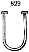
But although from 20 to 30 fathoms be the common length of a pump-lift, it sometimes becomes necessary to make it much longer, when no place can be found in the shaft for lodging a cistern, on account of the tubbing. Hence a pump-lift has been occasionally extended to 70 fathoms; which requires extraordinary strength of materials. The best plan for collaring the pumps in the pit, and keeping them steady in a perpendicular line, is to fix a strong bunton of timber under the joints of each pipe; and to attach the pipes firmly to these buntons by an iron collar, with screws and nuts, as represented in fig. 829.
The water obtained in sinking through the successive strata is, in ordinary cases, conducted down the walls of the shaft; and if the strata are compact, a spiral groove is cut down the sides of the shaft, and when it can hold no more, the water is drawn off in a spout to the nearest pump-cistern; or a perpendicular groove is cut in the side of the shaft, and a square box-pipe either sunk in it, flush with the sides of the pit, or it is covered with deal boards well fitted over the cavity. Similar spiral rings are formed in succession downwards, which collect the trickling streams, and conduct them into the nearest cistern; or rings, made of wood or cast iron, are inserted flush with the sides of the pipe; and the water is led from one ring to another, through perpendicular pipes, until the undermost ring is full, when it delivers its water into the nearest pump-cistern. Keeping the shaft dry is very important to the comfort of the miners, and the durability of the work.
When an engine shaft happens to pass through a great many beds of coal, a gallery a few yards long is driven into each coal-seam, and a bore then put down from one coal to another, so that the water of each may pass down through these bores to the pump-cisterns.
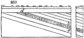
While a deep pit is sinking, a register is kept of every part of the excavations, and each feeder of water is measured daily, to ascertain its rate of discharge, and whether it increases or abates. The mode of measurement, is by noting the time, with a seconds watch, in which a cistern of 40 or 50 gallons gets filled. There are three modes of keeping back or stopping up these feeders; by plank tubbing; iron tubbing; and by oak cribs. Let fig. 830. represent the sinking of a shaft through a variety of strata, having a top cover of sand, with much water resting on the rock summit. Each plane of the coal-measure rises in a certain direction till it meets the alluvial cover. Hence, the pressure of the water at the bottom of the tubbing that rests on the summit of the rock, is as the depth of water in the superficial alluvium; and if a stratum a affords a great body of water, while the superjacent stratum b, and the subjacent c, are impervious to water; if the porous bed a be 12 feet thick, while no water occurs in the strata passed through from the rock head, until that depth (supposed to be 50 fathoms from the surface of the water in the cover); in this case, the tubbing or cribbing must sustain the sum of the two water pressures, or 62 fathoms; since the stratum a meets the alluvial cover at d, the fountain head of all the water that occurs in sinking. Thus we perceive, that though no water-feeder of any magnitude should present itself till the shaft had been sunk 100 fathoms; if this water required to be stopped up or tubbed off through the breadth of a stratum only 3 feet thick, the tubbing floodgate would need to have a strength to resist 100 fathoms of water-pressure. For though the water at first oozes merely in discontinuous particles through the open pores of the sands and sandstones, yet it soon fills them up, like a myriad of tubes, which transfer to the bottom the total weight of the hydrostatic column of 100 fathoms; and experience shows, as we have already stated, that whatever water occurs in coal-pits or in mines, generally speaking, proceeds from the surface of the ground. Hence, if the cover be an impervious bed of clay, very little water will be met with among the strata, in comparison of what would be found under sand.
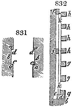
When several fathoms of the strata must be tubbed, in order to stop up the water-flow, the shaft must be widened regularly to admit the kind of tubbing that is to be inserted; the greatest width being needed for plank-tubbing, and the least for iron-tubbing. Fig. 831. represents a shaft excavated for plank-tubbing, where a, a, a are the impervious strata, b, b the porous beds water-logged, and c, c the bottom of the excavation, made level and perfectly smooth with mason-chisels. The same precautions are taken in working off the upper part of the excavation d, d. In this operation, three kinds of cribs are employed; called wedging, spiking, and main cribs. Besides the stout plank for making the tub, a quantity of well-seasoned and clean reeded deal is required for forming the joints; called sheeting deal by the workmen. This sheeting deal is always applied in pieces laid endwise, with the end of the fibres towards the area of the pit. Since much of the security from water depends on the tightness of the tub at its jointing with the rock, several plans have been contrived to effect this object; the most approved being represented in fig. 832. To make room for the lower wedging crib, the recess is excavated a few inches wider, as at c; and from b to c, sheeting deals are laid all round the circle, or a thin stratum of oakum is introduced. On this the wedging crib d is applied, and neatly jointed in the radius-line of the pit, each segment being drawn exactly to the circle: and at each of its segments sheeting deal is inserted. This wedging crib must be 10 inches in the bed, and 6 inches deep. The vacuity e, at the back of the crib, about 2 and a half inches wide, is filled with pieces of dry clean reeded deal, inserted endwise; which is regularly wedged with one set of wedges all round, and then with a second and a third set of wedges, in the same regular style, to keep the crib in a truly circular posture. By this process, well executed, no water can pass downwards by the back of the crib. The next operation is to fix spiking cribs f, to the rock, about 10 or 12 feet from the lower crib, according to the length of the planks to be used for the tubs. They must be set fair to the sweep of the shaft, as on them its true circular figure depends. The tubbing deals k, must now be fixed. They are 3 inches thick, 6 broad, and planed on all sides, with the joints accurately worked to the proper bevel for the circle of the pit. The main cribs g, g, are then to be placed as counterforts, for the support and strength of the tubbing. The upper ends of the first set of tub-planks being cut square and level all round, the second spiking crib l, is fixed, and another set of tubbing deals put round like the former, having sheeting deal inserted betwixt the ends of the two sets at f. When this is wedged, the cribs h, h, are placed.
Oak cribbing is made with pieces of the best oak, from 3 to 4 feet long, 10 inches in the bed, and 7 or 8 inches deep.
The third mode of tubbing, by means of iron cylinders cast in segments, is likely henceforth to supersede the wooden tubbing, from the great reduction in the price of iron, and its superior strength and durability. Each segment is adjusted piece to piece in the circular recess of the pit cut out for their reception. The flange for the wedging joint is best turned inwards. In late improvements of this plan, executed by Mr. Buddle, where the pressure amounted to several hundred feet, the segments were 6 feet long, 2 feet broad, and an inch thick, counterforted with ribs or raised work on the back; the lip of the flange was strong, and supported by brackets. These segments of the iron cylinder are set true to the radius of the pit; and every horizontal and perpendicular joint is made tight with a layer of sheeting deal. A wedging crib is fixed at the bottom, and the segments are built up regularly with joints like ashler-work. This kind of tubbing can be carried to any height, till the water finds an outlet at the surface, or till strata containing water can be tubbed off, as by the modes of tubbing already described. A shaft finished in this manner presents a smooth lining-wall of iron, the flanges being turned towards the outside of the cylinders. In this iron tubbing, no screw bolts are needed for joining the segments together; as they are packed hard within the pit, like the staves of a cask. There is a shaft in the Newcastle district, where 70 fathoms have been executed in this way, under the direction of Mr. Buddle.
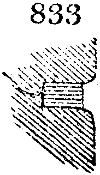
When a porous thin bed or parting betwixt two impervious strata, gives out much water, or when the fissures of the strata, called cutters, are very leaky, the water can be completely stopped up by the improved process of wedging. The fissure is cut open with chisels, to a width of two, and a depth of seven inches, as represented in fig. 833. The lips being rounded off about an inch and a half, pieces of clean deal are then driven in, whose face projects no further than the contour of the lips; when the whole is firmly wedged, till the water is entirely stopped. By sloping back the edges of the fissures, and wedging back from the face of the stone, it is not liable to burst or crack off in the operation, as took place in the old way, of driving in the wedge directly.
Ventilation of Engine Pits.—In ordinary cases, while the sinking of the shaft is going on, the brattice walls produce a circulation, in consequence of the air being slightly lighter in one compartment than in another. If this does not occur, the circulation of air must be produced by artificial means. The most approved contrivance is, to cover the engine compartment of the shaft with deals, leaving apertures for the pump-spears and tackling to pass through, with hatch-doors for the men, and to carry a brick flue at least 3 feet square, in a horizontal direction, from the mouth of that compartment to an adjoining high chimney connected with a furnace, as represented in fig. 834. a, a, are double doors, for the fireman to supply fuel by; b, the mouth of the horizontal flue; c, the furnace; d, the ash-pit; e, the furnace; f, the upright chimney for draught, from 50 to 100 feet high, from 8 to 10 feet square at bottom, and tapering upwards to 3 or 4 feet square inside. Such a furnace and chimney are also needed for ventilating the coal-mine through all its underground workings. When a great quantity of gas issues from one place in a pit, it is proper to carry it up in a square wooden pipe, which terminating at some distance above the surface in a helmet-shaped funnel, fitted to turn like a vane, may cause considerable ventilation of itself; or the top of such a pipe may be connected with a small fireplace, which will cause a rapid current up through it, from the pit. The stones and rubbish produced in sinking, are drawn up with horse-gins, when the pit is not deep; but in all shafts of considerable depth, a steam engine is used, and the workmen have now more confidence in them, as to personal safety, than in machines impelled by horses.
The great collieries of Newcastle are frequently worked by means of one shaft divided into compartments, which serves as an engine-pit, and coal-pits, and by these the whole ventilation is carried on to an extent and through ramifications altogether astonishing. This system has been adopted on account of the vast expense of a large shaft, often amounting to 60,000l. or 80,000l., including the machinery. The British collieries, however, are in general worked by means of an engine-pit, and a series of other pits, sunk at proper distances for the wants of the colliery.
WORKING OF COAL.
A stratum, bed, or seam of coal, is not a solid mass, of uniform texture, nor always of homogeneous quality in burning. It is often divided and intersected, with its concomitant strata, by what are named partings, backs, cutters, reeds, or ends. Besides the chief partings at the roof and pavement of the coal seam, there are subordinate lines of parting in the coal mass, parallel to these of variable dimensions. These divisions are delineated in fig. 835., where A, B, C, D, E F G D, represent a portion of a bed of coal, the parallelogram A B D C the parting at the roof, and E F G the parting at the pavement; a b, b c, d e, and e f, are the subordinate or intermediate partings; g h, i k, l m, the backs; o p, p q, r s, s t, u v, and v w, the cutters. It is thus manifest that a bed of coal, according to the number of these natural divisions, is subdivided into solid figures of various dimensions, and of a cubical or rhomboidal shape.
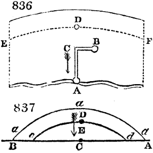
When the engine-pit is sunk, and the lodgement formed, a mine is then run in the coal to the rise of the field, or a cropping from the engine-pit to the second pit. This mine may be 6 or 8 feet wide, and carried either in a line directly to the pit bottom, or at right angles to the backs or web of the coal, until it is on a line with the pit, where a mine is set off, upon one side, to the pit bottom. This mine or gallery is carried as nearly parallel to the backs as possible, till the pit is gained. Fig. 836. represents this mining operation. A is the engine-pit. B, the second or bye-pit. A C, the gallery driven at right angles to the backs. C B, the gallery set off to the left hand, parallel to the backs. The next step is to drive the drip-head or main-levels from the engine-pit bottom, or from the dip-hand of the backset immediately contiguous to the engine-pit bottom. In this business, the best colliers are always employed, as the object is to drive the gallery in a truly level direction, independently of all sinkings or risings of the pavement. For coal seams of ordinary thickness, this gallery is usually not more than 6 feet wide; observing to have on the dip side of the gallery a small quantity of water, like that of a gutter, so that it shall always be about 4 or 6 inches deep at the forehead upon the dip-wall. When the level is driven correctly, with the proper depth of water, it is said to have dead water at the forehead. In this operation, therefore, the miner pays no regard to the backs or cutters of the coal; but is guided in his line of direction entirely by the water-level, which he must attend to solely, without regard to slips or dislocations of the strata throwing the coal up or down. In the last figure, the coal-field is a portion of a basin; so that if the shape be uniform and unbroken, and if any point be assumed a dipping from the crop, as D, the level lines from that point will be parallel to the line of crop, as D E, D F, and the levels from any point whatever a-dipping, will be also parallel to these; and hence, were the coal-field an entire elliptical basin, the dip-head levels carried from any point would be elliptical, and parallel to the crop. If, as is more commonly the case, the coal-field be merely a portion of a basin, formed by a slip of the strata, as represented in fig. 837., where a, a, a, is the crop, and A B, a slip of great magnitude, forming another coal-field on the side C, then the crop not only meets the alluvial cover, but is cut off by the slip at A and at B. Should any point, therefore, be assigned for an engine-pit, the levels from it will proceed in a line parallel to the crop, as D d, D c, and the level on both sides of the engine-pit will be also cut off by the slip A B. In this figure, the part included between the two curve lines, is the breadth or breast of coal-field won by the engine-pit D; what is not included, is termed the under-dip coal, and can be worked only by one or more new winnings towards the dip, according to circumstances.