C.
Reading edition
CABLE. (Cable, Fr.; Ankertau, Germ.) A strong rope or chain, connecting the ship with the anchor for the purpose of mooring it to the ground. The sheet anchor cable is the strongest, and is used at sea; the stream cable is more slender, being used chiefly in rivers. A cable’s length is 120 fathoms. The greatest improvement in mooring vessels has been the introduction of the chain cable, which, when duly let out, affords in the weight of its long catenary curve, an elastic tension and play to the ship under the pressure of wind. The dead strain upon the anchor is thus greatly reduced, and the sudden pull by which the flukes or arms are readily snapped is in a great measure obviated. The best iron cables are chains made of links, bound and braced by rods across their middle. Experience has taught that the ends of these links wear out much sooner than the sides. To remedy this evil, Mr. Hawkes, iron manufacturer, obtained a patent in July, 1828, for constructing these anchor chains with links considerably stouter at the ends than in the middle. With this view, he forms the short rods of iron, of which the links are to be made, with swells or protuberances about one third of their length from each of their ends, so that when these are welded together, the slenderer parts are at the sides, and the thicker at the ends of the elliptic links. Such rods as the above are formed at once by rolling, swagging, or any other means. When the link is welded, it may be strengthened, by a brace or stretcher fixed across the middle.
The first avowed proposal to substitute iron cables for cordage in the sea service, was made by Mr. Slater, surgeon of the navy, who obtained a patent for the plan in 1808, though he does not seem to have had the means of carrying it into effect; a very general misfortune with ingenious projectors. It was Captain Brown of the West India merchant service who, in 1811, first employed chain cables in the vessel Penelope, of 400 tons burden, of which he was captain. He made a voyage in this ship from England to Martinique and Guadaloupe and home again, in the course of four months, having anchored many times in every variety of ground without any accident. He multiplied his trials, and acquired certain proofs that iron might be substituted for hemp in making cables, not only for mooring vessels, but for the standing rigging. Since this period chain cables have been universally introduced into all the ships of the royal navy, but the twisted links employed at first by Brown, have been replaced by straight ones, stayed in the middle with a cross rod, the contrivance of Mr. Brunton, which was secured by patent in this country and in France; but the latter patent was suffered to fall from not being acted upon within the two years specified by law.
The first thing to be considered in the manufacture of iron cables is, to procure a material of the best quality, and, in using it, always to keep in view the direction of the strain, in order to oppose the maximum strength of the iron to it. The best form of the links may be deduced from the following investigation.
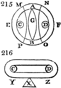
Let A B fig. 215. be a circular link or ring, of one inch rod iron, the outer circumference of the ring being 15 inches, and the inner 9. If equal opposite forces be applied to the two points of the link C D, pulling C towards E, and D towards F, the result will be, when the forces are sufficiently intense, that the circular form of the link will be changed into another form with two round ends and two parallel sides, as seen in fig. 216. The ratio of the exterior to the interior periphery which was originally as 15 to 9, or 5 to 3, is no longer the same in fig. 216. Hence there will be a derangement in the relative position of the component particles, and consequently their cohesion will be progressively impaired, and eventually destroyed. In fig. 215. the segment M N of the outside periphery being equal to 3 inches, the corresponding inside segment will be 3⁄5 of it, or 14⁄5 inches. If this portion of the link, in consequence of the stretching force, comes to be extended into a straight line, as shown in fig. 216., the corresponding segments, interior and exterior, must both be reduced to an equal length. The matter contained in the 3 inches of the outside periphery must therefore be either compressed, that is, condensed into 14⁄5 inch, or the inside periphery, which is only 14⁄5 inch already, must be extended to 3 inches; that is to say, the exterior condensation and the interior expansion must take place in a reciprocal proportion. But, in every case, it is impossible to effect this contraction of one side of the rod, and extension of the other, without disrupture of the link.
Let us imagine the outside periphery divided into an infinity of points, upon each of which equal opposite forces act to straighten the curvature: they must undoubtedly occasion the rupture of the corresponding part of the internal periphery. This is not the sole injury which must result; others will occur, as we shall perceive in considering what passes in the portion of the link which surrounds C D, fig. 216., whose length is 41⁄2 inches outside, and 21⁄10 inside. The segments M P and N O, fig. 215., are actually reduced to semi-circumferences, which are inside no more than half an inch, and outside as before. There is thus contraction in the interior, with a quicker curvature or one of shorter radius in the exterior. The derangement of the particles takes place here, in an order inverse to that of the preceding case, but it no less tends to diminish the strength of that portion of the link; whence we may certainly conclude that the circular form of cable links is an extremely faulty one.
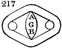
Leaving matters as we have supposed in fig. 215., but suppose that G is a rod introduced into the mail, hindering its two opposite points A B from approximating. This circumstance makes a remarkable change in the results. The link pulled as above described, must assume the quadrilateral form shown in fig. 217. It offers more resistance to deformation than before; but as it may still suffer change of shape, it will lose strength in so doing, and cannot therefore be recommended for the construction of cables which are to be exposed to very severe strains.
Supposing still the link to be circular, if the ends of the stay comprehended a larger portion of the internal periphery, so as to leave merely the space necessary for the plan of the next link, there can be no doubt of its opposing more effectively the change of form, and thus rendering the chain stronger. But, notwithstanding, the circular portions which remain between the points of application of the strain and the stay, would tend always to be straightened, and of consequence to be destroyed. Besides, though we could construct circular links of sufficient strength to bear all strains, we ought still to reject them, because they would consume more materials than links of a more suitable form, as we shall presently see.
The effect of two opposite forces applied to the links of a chain, is, as we have seen, to reduce to a straight line or a straight plane every curved part which is not stayed; whence it is obvious that twisted links, such as Brown first employed, even with a stay in their middle, must of necessity be straightened out, because there is no resistance in the direction opposed to the twist. A cable formed of twisted links, for a vessel of 400 tons stretches 30 feet, when put to the trial strain, and draws back only 10 feet. This elongation of 20 feet proceeds evidently from the straightening of the twist in each link, which can take place only by impairing the strength of the cable.
From the preceding remarks, it appears that the strongest links are such as present, in their original form, straight portions between the points of tension; whence it is clear that links with parallel sides and round ends, would be preferable to all others, did not a good cable require to be able to resist a lateral force, as well as one in the direction of its length.
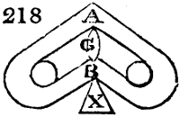
Let us suppose that by some accident the link fig. 216. should have its two extremities pulled towards Y and Z, whilst an obstacle X, placed right opposite to its middle, resisted the effort. The side of the link which touches X, would be bent inwards; but if as in fig. 218., there is a stay A G B, the two sides would be bent at the same time; the link would notwithstanding assume a faulty shape.
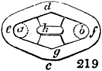
In thus rejecting all the vicious forms, we are naturally directed to that which deserves the preference. It is shown in fig. 219. This link has a cast-iron stay with large ends, it presents in all directions a great resistance to every change of form; for let it be pulled in the direction a b, against an obstacle c, it is evident that the portions d e and d f, which are supported by the parts g e and g f, cannot get deformed or be broken without the whole link giving way. As the matter composing g e and g f cannot be shortened, or that which composes d e and d f be lengthened, these four sides will remain necessarily in their relative positions, by virtue of the large-ended stay h, whose profile is shown in fig. 220.
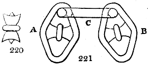
We have examined the strength of a link in every direction, except that perpendicular to its plane. Fig. 221. represents the assemblage of three links in the above predicament; but we ought to observe, that the obstacle C, placed between the links A B, must be necessarily very small, and could not therefore resist the pressure or impact of the two lateral links.
Process of manufacturing iron cables.—The implements and operations are arranged in the following order:—
1. A reverberatory furnace (see Iron), in which a number of rods or round bars of the best possible wrought-iron, and of proper dimensions, are heated to bright ignition.
2. The cutting by a machine of these bars, in equal lengths, but with opposite bevels, to allow of the requisite crossing and splicing of the ends in the act of welding.
3. The bending of each of these pieces by a machine, so as to form the links; the last two operations are done rapidly while the iron is red-hot.
4. The welding of the links at small forge fires, fitted with tools for this express purpose, and the immediate introduction of the stay, by means of a compound lever press.
5. Proving the strength of the cables by an hydraulic press, worked by two men turning a winch furnished with a fly wheel.
The furnace is like those used in the sheet-iron works, but somewhat larger, and needs no particular description here.
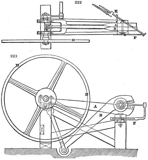
Figs. 222. and 223. are a plan and elevation of the shears with which the rods are cut into equal pieces, for forming each a link. It is moved at Mr. Brunton’s factory by a small steam engine, but, for the sake of simplicity, it is here represented worked by four or more labourers, as it may be in any establishment. These must be relieved however frequently by others, for I believe each shears’ machine is calculated to require nearly one horse in steam power. It is portable and must be placed in the neighbourhood of both the furnace and bending machine.
A and B are the two cast-iron limbs of the shears. The first is fixed and the second is movable by means of a crank shaft C, driven by a heavy fly-wheel weighing 7 or 8 cwt.
The cutting jaws G are mounted with pieces of steel which are made fast by bolts, and may be changed at pleasure.
E, the bar of iron to be cut. It is subjected, immediately upon being taken out of the fire, to the shears, under a determinate uniform angle, care being taken not to let it turn round upon its axis, lest the planes of the successive incisions should become unequal.
F is a stop which serves to determine, for the same kind of chain, the equality of length in the link pieces.
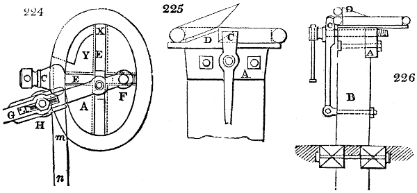
Figs. 224, 225, 226. plan and elevations of the machine for bending the links into an elliptic form. It is represented at the moment when a link is getting bent upon it.
A is an elliptic mandrel of cast-iron; it is fixed upon the top of a wooden pillar B, solidly supported in the ground. C is the jaw of the vice, pressed by a square-headed screw against the mandrel A.
D part of the mandrel comprehended between X and Y, formed as an inclined plane, so as to preserve an interval equal to the diameter of the rod between the two surfaces that are to be welded together.
E rectangular slots (shears) passing through the centre of the nut of the mandrel, in which each of the pins F may be freely slidden.
G horizontal lever of wrought-iron six feet long. It carries at H a pulley or friction-roller of steel, whose position may be altered according to the diameter of the links. It is obvious that as many mandrels are required as there are sizes and shapes of links.
The piece of iron intended to form a link being cut, is carried, while red-hot, to the bending machine, where it is seized with the jaw of the vice C, by one of its ends, the slant of the cut being turned upwards; this piece of iron has now the horizontal direction m n; on pushing the lever G in the line of the arrow, the roller H will force m n to be applied successively in the elliptic groove of the mandrel; thus finally the two faces that are to be welded together will be placed right opposite each other.
The length of the small diameter of the ellipse ought to exceed by a little the length of the stay-piece, to allow of this being readily introduced. The difference between the points F, E is equal to the difference of the radii vectores of the ellipse. Hence it will be always easy to find the eccentricity of the ellipse.
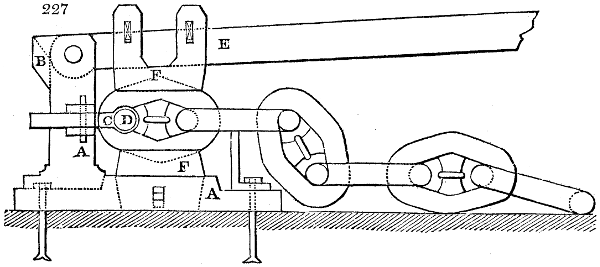
Fig. 227. is a lever press for squeezing the links upon their stays, after the links are welded. This machine consists of a strong cast-iron piece A, in the form of a square, of which one of the branches is laid horizontally, and fixed to a solid bed by means of bolts; the other branch, composed of two cheeks, leaving between them a space of two inches, stands upright. These two cheeks are united at top, and on the back of their plane by a cross piece B. C, a rectangular staple, placed to the right and left of the cheeks through which is passed the mandrel D, which represents and keeps the place of the following link. E, is a press lever, 6 feet long. F, clamp and counterclamp, between which the link is pressed at the moment when the stay is properly placed. There are other clamps, as well as staples C, for changing with each changed dimension of links.
The links bent, as we have seen, are carried to the forge hearth to be welded, and to receive their stay; two operations performed at one heating. Whenever the welding is finished, while the iron is still red-hot, the link is placed upright between the clamps F; then a workman introduces into the staple the mandrel D, and now applies the stay with a pair of tongs or pincers, while another workman strikes down the lever E forcibly upon it. This mechanical compression first of all joins perfectly the sides of the link against the concave ends of the stay, and afterwards the retraction of the iron on cooling increases still more this compression.
If each link be made with the same care, the cable must be sound throughout. It is not delivered for use however till it be proved by the hydraulic press, at a draw-bench made on purpose. The press is an horizontal one, having the axis of its ram in the middle line of the draw-bench, which is about 60 feet long, and is secured to the body of the press by strong bolts.
The portion of chain under trial, being attached at the one end to the end of the ram of the press, and at the other to a cross-bar at the extremity of the draw-bench, two men put the press in action, by turning the winch which works by a triple crank three forcing pumps alternately; the action being equalized by means of a heavy fly-wheel. As long as the resistance does not exceed the force of two men, the whole three pumps are kept in play. After a while one pump is thrown out of geer and next another, only one being worked towards the conclusion. The velocity of the ram being retarded first one third and next two thirds, gives the men a proportional increase of mechanical power.
The strength of two average men thus applied being computed, enables us to know at every instant the resistance opposed by the chain to the pressure of the ram. The strain usually applied to the stronger cables is about 500 tons.
The side beams of the draw-bench are of cast-iron, 6 inches in diameter; the different pieces composing it are adjusted to each other end-wise by turned joints. Props also of cast-iron support the beams two feet asunder, and at the height of 30 inches above the ground. The space between them is filled with an oak plank on which the trial chain is laid.
Strength of iron-cables compared to hemp cables:—
Iron Cables. Diameter of Iron Rod. Hemp Cables. Circumference of Rope. Resistance.
Inches. Inches. Tons.
0 7⁄8 9 12
1 10 18
1 1⁄8 11 26
1 1⁄4 12 32
1 5⁄16 13 35
1 3⁄8 14 to 15 38
1 1⁄2 16 44
1 5⁄8 17 52
1 3⁄4 18 60
1 7⁄8 20 70
2 22 to 24 80
It would be imprudent to put hemp cables to severer strains than those indicated in the preceding table, drawn up from Brunton’s experiments; but the iron cables of the above sizes will support a double strain without breaking. They ought never in common cases however to be exposed to a greater stress. A cable destined for ships of a certain tonnage, should not be employed in those of greater burden. Thus treated it may be always trusted to do its duty, and will last longer than the ship to which it belongs. A considerable part of this decided superiority which iron cables have over hemp ones, is undoubtedly due to the admirable form contrived by Brunton. Repeated experiments have proved that his cables possess double the strength of the iron rods with which they are made—a fact which demonstrates that no stronger form can be devised or is in fact possible.
One of the most valuable qualities of iron cables is their resisting lateral as well as longitudinal strains as explained under figs. 219. and 221.
Vessels furnished with such cables have been saved by them from the most imminent peril. The Henry, sent out with army stores during the peninsular war, was caught on the northern coast of Spain in a furious storm. She run for shelter into the Bay of Biscay among the rocks, where she was exposed for three days to the hurricane. She possessed fortunately one of Brunton’s 70 fathom chain cables, which held good all the time, but it was found afterwards to have had the links of its lower portion polished bright by attrition against the rocky bottom. A hemp cable would have been speedily torn to pieces in such a predicament.
In the contracts of the Admiralty for chain cables for the British navy, it is stipulated that “the iron shall have been manufactured in the best manner from pig iron, smelted from iron-stone only, and selected of the best quality for the purpose, and shall not have received in any process whatever subsequent to the smelting, the admixture of either the cinder or oxides produced in the manufacture of iron; and shall also have been puddled in the best manner upon iron bottoms, and at least three times sufficiently drawn out at three distinct welding heats, and at least twice properly fagotted.”
The following is a table of the breaking proof of chain cables, and of the iron for the purpose of making them, also of the proofs required by her majesty’s navy for chains.
Size of Bolt. Proof of Bolt. Proof of Chain. Navy Proof of Chain.
Inches. Tons. Cwt. Tons. Cwt. Tons.
1⁄2 5 7 8 11 4 1⁄2
5⁄8 8 7 13 4 5 1⁄2
3⁄4 12 1 19 5 10 7⁄8
7⁄8 16 4 26 5 13 3⁄4
1 21 8 34 5 18
1 1⁄8 27 2 48 15 22 3⁄4
1 1⁄4 33 10 53 11 28 1⁄2
1 3⁄8 40 10 65 0 34
1 1⁄2 48 4 77 0 40 1⁄2
1 5⁄8 56 11 90 10 47 1⁄2
1 3⁄4 65 12 105 0 55 1⁄8
1 7⁄8 75 6 120 10 63 1⁄4
2 85 14 137 0 72
2 1⁄8 96 15 155 0 81 1⁄4
In Brunton’s cable the matter in the link is thrown very much into one plane; the link being of an oval form, and provided with a stay. As there are emergencies in which the cable must be severed, this is accomplished in those of iron by means of a bolt and sheckle (shackle), at every fathom or two fathoms; so that by striking out this bolt or pin, this cable is parted with more ease than a hempen one can be cut.
CACAO, BUTTER OF. See Cocoa, and Oils, Unctuous.
CADMIUM, is a metal discovered about the beginning of the year 1818. It occurs chiefly in Silesia in several ores of zinc; and may be readily recognized by means of the blowpipe; for at the first impression of the reducing or smoky part of the flame, the ores containing cadmium stain the charcoal all round them with a reddish yellow circle of oxide of cadmium. The Silesian native oxide of zinc contains from 11⁄2 to 11 per cent. of cadmium.
The cadmium may be extracted by dissolving the ore in sulphuric acid, leaving the solution acidulous, and diluting it with water, then transmitting through it a stream of sulphuretted hydrogen, till the yellow precipitate ceases to fall. This powder which is sulphuret of cadmium, is to be dissolved in concentrated muriatic acid, the excess of which is to be expelled by evaporation; and the muriatic salt being dissolved in water, carbonate of ammonia is to be added in excess, whereby the cadmium separates as a carbonate, while the small portion of adhering copper or zinc is retained in solution by the ammonia. Herapath has shown that, in distilling zinc per descensum (see Zinc), the first portions of gaseous metal which are disengaged burn with a brown flame and deposit the brown oxide of cadmium.
Cadmium has the colour and lustre of tin; and is susceptible of a fine polish. Its fracture is fibrous; it crystallizes readily in regular octahedrons, and when it suddenly solidifies, its surface gets covered with fine mossy vegetations. It is soft, easily bent, filed, and cut, soils like lead any surface rubbed with it. It is harder and more tenacious than tin, and emits a creaking sound when bent, like that metal. It is very ductile, and may be drawn out into fine wire, and hammered into thin leaves without cracking at the edges. Its specific gravity, after being merely melted, is 8·604; and 8·6944 after it has been hammered. It is very fusible, melting at a heat much under redness; indeed at a temperature little exceeding that of boiling mercury, it boils and distils over in drops. Its vapours have no smell. It is but slightly altered by exposure to air. When heated in the atmosphere, it readily takes fire, and burns with a brownish yellow smoke which is destitute of smell. In strong acids it dissolves with disengagement of hydrogen, and forms colourless solutions. Chromate of potash causes no precipitate in them, unless zinc or lead be present.
There is only one oxide of cadmium, the brown above-mentioned. Its specific gravity is 8·183. It is neither fusible nor volatile at a very high temperature. When in the state of a hydrate it is white. The oxide of cadmium consists of 87·45 parts of metal, and 12·55 oxygen in 100 parts. Berzelius states its atomic weight to be 55·833 to hydrogen 1·000. Its sulphuret has a fine orange yellow colour, and would form a beautiful pigment, could the metal be found in sufficient quantity for the purposes of art. The sulphate is applied to the eyes by surgeons for removing specks of the cornea.
CAFEINE. A chemical principle discovered in coffee, remarkable for containing much azote. See Coffee.
CAJEPUT OIL is obtained from the leaves of the tree called Melaleuca Leucadendron by Linnæus, which grows upon the mountains of Amboyna, and in other of the Molucca islands. It is procured by distillation of the dried leaves along with water, is prepared in great quantities in the island of Banda, and sent to Holland in copper flasks. Hence as it comes to us, it has a green colour. It is very limpid, lighter than water, of a strong smell resembling camphor, and pungent taste like cardamoms. When rectified the copper remains in the retort, and the oil comes over colourless. It is used in medicine as a stimulant. See Oils Ethereous.
CALAMANCO. A sort of woollen stuff of a shining appearance, chequered in the warp, so that the checks are seen only upon one side.
CALAMINE. A native carbonate of zinc. See Zinc.
CALCAREOUS EARTH. (Terre calcaire, Fr.; Kalkerde, Germ.) Commonly denotes lime, in any form; but, properly speaking, it is pure lime.
CALCAREOUS SPAR. Crystallized native carbonate of lime.
CALCEDONY. A hard mineral of the siliceous family, often cut into seals. Under it may be grouped common calcedony, heliotrope, chrysoprase, plasma, onyx, sardonyx, and sard.
CALCHANTUM. The ancient name of native copperas or sulphate of iron.
CALCINATION, is the chemical process of subjecting metallic bodies to heat with access of air, whereby they are converted into a pulverulent matter, somewhat like lime in appearance, called calx in Latin. The term calcination, however, is now used when any substance whatever is exposed to a roasting heat.
CALCIUM. The metallic basis of lime. See Lime.
CALC-SINTER. The incrustations of carbonate of lime upon the ground, or the pendulous conical pieces called stalactites, attached to the roofs of caverns, are so called.
CALC-TUFF. A semi-hard irregular deposit of carbonate of lime, formed from the waters of calcareous springs.
CALCULUS. The stony-looking morbid concretion, occasionally formed in the bladder of urine, gall-bladder, cystic duct, kidneys, and other parts of living animals. Its examination belongs to medical chemistry.
CALENDER, (Calandre, Fr.; Kalander, Germ.) a word derived from the Greek kalindros (cylinder), is the name of a machine, consisting of two or more cylinders, revolving so nearly in contact with each other that cloth passed through between them is smoothed, and even glazed, by their powerful pressure. It is employed either to finish goods for the market, or to prepare cotton and linen webs for the calico-printer, by rendering their surfaces level, compact, and uniform. This condensation and polish, or satinage, as the French call it, differ in degree according to the object in view, and may be arranged into three distinct series. 1. For goods which are to receive the first impression by the block, a very strong pressure is required; for, upon the uniformity of the polish, the neatness and regularity of the printing, and the correspondence of its members, depend. In many establishments the calico is passed twice through the calender before being sent to the tables. 2. The pieces already dyed up at the madder bath, or otherwise, and which remain to be filled in with other colours, or grounded-in, as it is technically styled, must receive a much less considerable gloss. This is a principle every where admitted and acted upon, because the outline of the figured design being deranged by the washing, and sometimes in consequence of the peculiar texture of the cloth, the printer, in order to apply his grounding blocks properly, and to fit them to the contours of the figures already impressed, is obliged to stretch the piece sometimes in the direction of the warp, and sometimes of the weft, which would be impossible if they had been hard glazed by the calender. 3. The degree of glazing given to finished goods depends upon the taste of purchasers, and the nature of the article; but it is, in general, much less than for the first course of block-printing.
The most complete calender probably in existence is that used by some of the eminent calico-printers of Alsace, as contrived by M. Charles Dollfus, and constructed by MM. Witz, Blech, and Co. 1. It passes two pieces at once, and thus does double the work of any ordinary machine. 2. It supersedes the necessity of having a workman to fold up the goods, as they emerge from the calender, with the aid of a self-acting folder. 3. It receives, at pleasure, the finished pieces upon a roller, instead of laying them in folds; and, by a very simple arrangement, it hinders the hands of the workmen from being caught by the rollers.
Calenders, in consequence of the irregular demand for foreign orders and shipments, are worked very irregularly, being sometimes overloaded with duty, and at others altogether unemployed. A machine which can, when required, turn out a double quantity of goods must, therefore, be a desirable possession. For the first course of the printers, where high calendering is necessary, the goods are usually passed twice through between two paper cylinders, to give that equality of surface which could not be obtained by one passage, however strong the pressure; and therefore the simplification of this calender will prove no economy. Besides, in order to increase the pressure to the requisite degree, the cylinders would need to be made bulging at their middle part, and with such cylinders common smoothing could not be given; for the pieces would be glazed in the central line, and rough towards the edges. For pieces already printed in part, and requiring only to be grounded-in for other colours, the system of double effect has fewer objections, as a single passage through the excellent calender described under Bleaching, page 134., is found to answer very well.
The most remarkable feature of M. Dollfus’s machine is its being managed by a single workman. Six or eight pieces are coiled upon the feed-roller, and they are neither pasted nor stitched together, but the ends are merely overlapped half a yard or so. The workman is careful not to enter the second piece till one third or one half of the first one has passed through on the other side, to prevent his being engrossed with two ends at a time. He must, no doubt, go sometimes to the one side and sometimes to the other of the machine to see that no folds or creases occur, and to be ready for supplying a fresh piece as the preceding one has gone through. The mechanism of the folder in the Alsace machine is truly ingenious: it performs extremely well, really saves the attendance of an extra workman, and is worthy the attention of manufacturers intent upon economising hand labour. The lapping-roller works by friction, and does its duty fully better than similar machines guided by the hand.
The numerous accidents which have happened to the hands of workmen engaged in calenders should direct the attention towards its effective contrivance for preventing such misfortunes. These various improvements in the Alsace machine may be easily adapted to the ordinary calenders of almost every construction.
The folder is a kind of cage, in the shape of an inverted pyramid, shut on the four sides, and open at top and bottom: the top orifice is about five inches, the bottom one an inch and a half: the front and the back, which are about four feet broad, are made of tin-plate or smooth pasteboard, and the two sides are made of strong sheet-iron; the whole being bolted together by small bars of iron. Upon the sheet-iron of the sides, iron uprights are fixed, perforated with holes, through which the whole cage is supported freely by means of studs that enter into them. One of the uprights is longer than the other, and bears a slot with a small knob, which, by means of the iron piece, joins the guide to the crank of the cylinder, and thereby communicates to the cage a seesaw movement: at the bottom extremity of the great upright, there is a piece of iron in the shape of an anchor, which may be raised, or lowered, or made fast, by screws.
At the ends of this anchor are friction-rollers, which may be drawn out or pushed back and fixed by screws: these rollers lift alternately two levers made of wood, and fixed to a wooden shaft.
The paws are also made of wood: they serve to lay down alternately the plies of the cloth which passes upon the cage, and is folded zigzag upon the floor, or upon a board set below the cage: a motion imparted by the seesaw motion of the cage itself. See Stretching Machine.
To protect the fingers of the workmen, above the small plate of the spreading-board or bar, there is another bar, which forms with the former an angle of about 75°: they come sufficiently near together for the opening at the summit of the angle to allow the cloth to pass through, but not the fingers. See Bulletin de la Société Industrielle de Mulhausen, No. 18.
I shall now describe, more minutely, the structure of the powerful but less complicated calender mechanisms employed in the British manufactories.
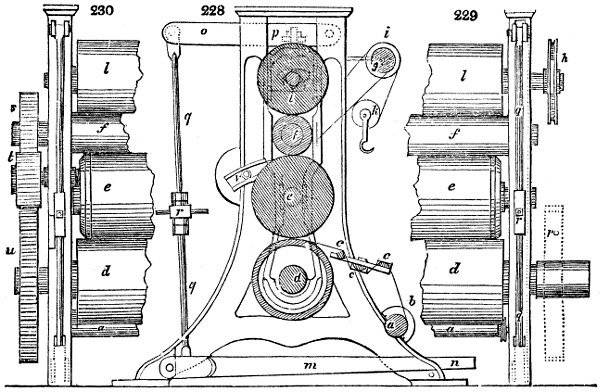
A front elevation of a four-rollered calender (five rollers are often introduced) for glazing goods is given in fig. 228. d l are two pasteboard or paper cylinders, each 20 inches in diameter, whose structure will be presently described: f is a cast-iron cylinder turned perfectly smooth (its fellow is often placed between e and d): it is eight inches in diameter outside, four inches inside, with two inches thickness of metal. e is another pasteboard cylinder, fourteen inches in diameter: the strong cast-iron frame contains the bushes in which the journals of the rollers turn. o p, is one of the pair of levers for communicating a graduated pressure according to the quality of the goods. Fig. 229, 230. are end views of the same machine to show the working geer. The wheel s, on the end of the upper iron cylinder, is ten inches in diameter; that on the end of the fellow iron cylinder below (when it is present) is thirteen inches; both are connected by the larger carrier wheel t. The lower wheel u is one third larger than the upper wheel, and therefore receives from the carrier wheel t, a proportionally slower motion, which it imparts to the central pasteboard roller e, lying upon it, causing it to move one third more slowly than the upper pasteboard roller. Thus a sort of sliding motion is produced, which, by rubbing their surfaces, glazes the goods.
The iron rollers are made hollow for the purpose of admitting either a hot roller of iron, or steam when hot calendering is required. The other cylinders used formerly to be made of wood, but it was liable to many defects. The advantage of the paper roller consists in its being devoid of any tendency to split, crack, or warp, especially when exposed to a considerable heat from the contact and pressure of the hot iron rollers. The paper, moreover, takes a vastly finer polish, and, being of an elastic nature, presses into every pore of the cloth, and smooths its surface more effectually than any wooden cylinder, however truly turned, could possibly do.
The paper cylinder is constructed as follows:—The axis of the cylinder is a strong square bar of the best wrought iron, cut to the proper length. Upon this bar a strong round plate of cast iron is first put, somewhat less in diameter than the cylinder when finished. A quantity of thick stout pasteboard is then procured, and cut into round pieces an inch larger in diameter than the iron plate. In the centre of the plates, and of every piece of the pasteboard, a square hole must be cut to receive the axis; and, the circle being divided into six equal parts, a hole must also be cut at each of the divisions, an inch or two within the rim. These pieces of pasteboard being successively put upon the axis, a long bolt of malleable iron, with a head at one end, and screwed at the other, is also introduced through each of the holes near the rim; and this is continued until a sufficient number of pasteboards are thus placed to form a cylinder of the length required, proper allowance being made for the compression which the pasteboard is afterwards to undergo. Another round plate is then applied, and, nuts being put upon the screws, the whole are screwed tight, and a cylinder formed. This cylinder is now to be placed in a stove, exposed to a strong heat, and must be kept there for at least several days; and, as the pasteboard shrinks by exposure to the heat, the screws must be frequently tightened until the whole mass has been compressed as much as possible. When the cylinder is thus brought to a sufficient degree of density it is removed from the stove; and, when allowed to cool, the pasteboard forms a substance almost inconceivably dense and hard. Nothing now remains but to turn the cylinder; and this is an operation of no slight labour and patience. The motion in turning must be slow, not exceeding about forty revolutions in a minute; the substance being now so hard and tough that tools of a very small size must be used to cut, or rather scrape it, until it is true. Three men are generally employed for the turning, even when the motion of the cylinder is effected by mechanical power, two being necessary to sharpen tools, for the third who turns, as quickly as he blunts them.
Let us suppose it to be a five-rollered machine: when a person stands in front of the calender, the cloth coming from behind above the uppermost cylinder 1, passes between 1 and 2: proceeding behind 2, it again comes to the front between 2 and 3: between 3 and 4 it is once more carried behind, and, lastly, brought in front between 4 and 5, where it is received, and smoothly folded on a clean board, or in a box, by a person placed there for the purpose. In folding the cloth at this time, care must be taken that it may be loosely done, so that no mark may appear until it be again folded in the precise length and form into which the piece is to be made up. The folding may be done either by two persons or by one, with the aid of two sharp polished spikes placed at a proper distance, to ascertain the length of the fold, and to make the whole equal. When folded into lengths, it is again folded across upon a smooth clean table, according to the shape intended, which varies with the different kinds of goods, or the particular market for which the goods are designed.
When the pieces have received the proper fold, the last operation previous to packing them is the pressing. This is commonly performed by placing a certain number of pieces, divided by thin smooth boards of wood, in a common screw press, similar to those used by printers for taking out the impression left by the types in the printing-press. Besides the wooden boards, a piece of glazed pasteboard is placed above and below every piece of cloth, that the outer folds may be as smooth and glossy as possible. The operation of the common screw press being found tedious and laborious, the hydraulic press is now in all well mounted establishments had recourse to. See Hydraulic Press.
No improvements that have taken place in calendering can exceed the power and facility of the water press: one of these presses may be worked by two men, who can with great ease produce a pressure of 400 tons; but, in considerable establishments, the presses are worked by power. See Bandanna.
The appearance and finish of the goods, in consequence of such an immense weight acting on them, are materially improved.
The press is also used for the purpose of packing; whereby the bale is rendered much more compact than formerly. It is commonly roped, &c., while in this compressed state; the dimensions, are therefore, greatly diminished from what they would otherwise be by any other method. For instance, the same quantity of goods packed in a bale are from one third to one half less bulky than if they were packed in a box with the utmost force of the hands.
For lawns and muslins of a light texture, the operation of smoothing requires a different process in some respects than close heavy fabrics. They only require to be slightly smoothed to remove any marks which they may have received at the bleaching; and, as their beauty depends rather on their transparency than their closeness, the more the cylindrical form of the yarn is preserved the better. They are therefore put through a small machine, consisting of three rollers or cylinders; and, as the power required to move this is small, the person who attends it generally drives it by a small winch; or the same effect may be produced by passing the muslins between only two or three rollers of the above calender, lightly loaded.
In the thick fabrics of cloth, including those kinds which are used for many parts of household furniture, as also those for female dress, the operation of glazing is used both to add to the original beauty of the cloth, and to render it more impervious to dust or smoke. The glazing operation is performed entirely by the friction of any smooth substance upon the cloth; and, to render the gloss brighter, a small quantity of bleached wax is previously rubbed over the surface. The operation of glazing by the common plan is very laborious, but the apparatus is of the most simple kind. A table is mounted with a thick stout cover of level and well-smoothed wood, forming an inclined plane; that side where the operator stands at work being the lowest. The table is generally placed near a wall, both for convenience in suspending the glazing apparatus, and for the sake of light. A long piece of wood is suspended in a groove formed between two longitudinal beams, placed parallel to the wall, and fixed to it. The groove resembles exactly the aperture between the shears of a common turning lathe. The lever, of which the groove may be supposed to be the centre or fulcrum, is faced at the bottom with a semi-cylindrical piece of finely polished flint, which gives the friction to the cloth stretched upon the table below. Above the flint are two cross handles, of which the operator lays hold, and moves them backward and forward with his hands, keeping the flint pressing slightly upon the cloth. When he has glazed a portion equal to the breadth of the flint, he moves his lever between the shears sidewise, and glazes a fresh part: thus he proceeds from one side or selvage of the cloth to the other: and when all which is upon the table is sufficiently glazed, he draws it over, and exposes a new portion to the same operation. To preserve the cloth at a proper tension, it may be wound smoothly upon a roller or beam, which being set so as to revolve upon its own axis behind the table, another roller to receive the cloth may be placed before, both being secured by a catch, acting in a ratchet wheel. Of late years, however, a great part of the labour employed in glazing cloth has been saved, as the common four or five bowl calender has been altered to fit this purpose by direct pressure.
As a matter of accommodation, the different processes of packing, cording of boxes, sheeting of trunks, and, in general, all the arrangements preparatory to shipments, and also the intimations and surveys necessary for obtaining drawbacks, debentures, or bounties, according to the excise laws, are generally conducted at the calender houses where goods are finished. These operations sufficiently account for the general meaning attached to the word.
CALICO-PRINTING (Impression d’Indiennes, Fr.; Zeugdruckerei, Germ.) is the art of impressing cotton cloth with topical dyes of more or less permanence. Of late years, silk and woollen fabrics have been made the subjects of a similar style of dyeing. Linens were formerly stained with various coloured designs, but since the modern improvements in the manufacture of cotton cloth they are seldom printed, as they are both dearer, and produce less beautiful work, because flax possesses less affinity than cotton for colouring matters.
This art is of very ancient date in India, and takes its English name from Calicut, a district where it has been practised with great success from time immemorial. The Egyptians, also, appear from Pliny’s testimony to have practised at a remote era some of the most refined processes of topical dyeing. “Robes and white veils,” says he, “are painted in Egypt in a wonderful way. They are first imbued, not with dyes, but with dye-absorbing drugs, by which, though they seem to be unaltered, yet, when immersed for a little while in a cauldron of the boiling dye-liquor, they are found to become painted. Yet, as there is only one colour in the cauldron, it is marvellous to see many colours imparted to the robe, in consequence of the influence of the excipient drug. Nor can the dye be washed out. A cauldron, which would of itself merely confuse the colours of cloths previously dyed, is thus made to impart several pigments from a single dye-stuff, painting as it boils.” The last expression pingitque dum coquit, is perfectly graphic and descriptive of calico-printing.
The cotton chintz counterpanes of great size, called pallampoors, which have been manufactured in Madras from the earliest ages, have in like manner peculiar dye-absorbing drugs applied to them with the pencil, as also wax, to protect certain parts of the surface from the action of the dye, and are afterwards immersed in a staining liquor, which, when wax is applied, is usually the cold indigo-vat, but without the wax is a hot liquor similar to the Egyptian. M. Koechlin Roder, of Mulhouse, brought home lately from India a rich collection of cloths in this state of preparation, which I saw in the cabinet of the Société Industrielle of that interesting emporium of calico-printing. The native implements for applying the wax and colouring bases are placed alongside of the cloths, and form a curious picture of primeval art. There is among other samples an ancient pallampoor, five French yards long, and two and a half broad, said to be the labour of Hindoo princesses, which must have taken a lifetime to execute. The printing machinery of great Britain has begun to supersede, for these styles of work, the cheapest hand labour of India.
Calico-printing has been for several hundred years practised by the oriental methods in Asia Minor and the Levant, but it was unknown as an English art till 1696, when a small print-ground was formed upon the banks of the Thames, near Richmond, by a Frenchman; probably a refugee from his own country, in consequence of the revocation of the edict of Nantes. Some time afterwards, a considerable printing work was established at Bromley Hall, in Essex, and several others sprung up successively in Surrey, to supply the London shops with chintzes, their import from India having been prohibited by act of parliament in 1700. The silk and woollen weavers, indeed, had all along manifested the keenest hostility to the use of printed calicoes, whether brought from the East or made at home. In the year 1680 they mobbed the India House in revenge for some large importations then made of the chintzes of Malabar. They next induced the government, by incessant clamours, to exclude altogether the beautiful robes of Calicut from the British market. But the printed goods, imported by the English and Dutch East India companies, found their way into this country, in spite of the excessive penalties annexed to smuggling, and raised a new alarm among the manufacturing population of Spitalfields. The sapient legislators of that day, intimidated, as would appear, by the East London mobs, enacted in 1720 an absurd sumptuary law, prohibiting the wearing of all printed calicoes whatsoever, either of foreign or domestic origin. This disgraceful enactment, worthy of the meridian of Cairo or Algiers, proved not only a death blow to rising industry in this ingenious department of the arts, but prevented the British ladies from attiring themselves in the becoming drapery of Hindostan. After an oppressive operation of ten years, this act was repealed by a partially enlightened set of senators, who were then pleased to permit what they called British calicoes, if made of linen warp, with merely weft of the hated cotton, to be printed and worn, upon paying a duty of no less than sixpence the square yard. Under this burden, English calico-printing could not be expected to make a rapid progress. Accordingly, even so lately as the year 1750, no more than 50,000 pieces of mixed stuff were printed in Great Britain, and that chiefly in the neighbourhood of London; whereas a single manufacturer, Mr. Coates of Manchester, now-a-days will turn off nearly twenty times that quantity, and there are very many others who manufacture several hundred thousand pieces per annum. It was not till about 1766 that this art migrated into Lancashire, where it has since taken such extraordinary development; but it was only after 1774 that it began to be founded upon right principles, in consequence of the repeal of that part of the act of 1730 which required the warp to be made of linen yarn. Henceforth the printer, though still saddled with a heavy duty of 3d. the square yard, was allowed to apply his colours to a homogeneous web, instead of the mixed fabric of linen and cotton substances, which differ in their affinities for dyes.
France pursued for some time a similar false policy with regard to calico-printing, but she emerged sooner from the mists of manufacturing monopoly than England. Her avowed motive was to cherish the manufacture of flax, a native product, instead of that of cotton, a raw material, for which prejudice urged that money had to be exported. Her intelligent statesmen of that day, fully seventy years ago, replied, that the money expended in the purchase of cotton was the produce of French industry, beneficially employed, and they therefore took immediate measures to put the cotton fabrics upon a footing of equality. Meanwhile the popular prejudices became irritated to such a degree, by the project of permitting the free manufacture and sale of printed cottons, that every French town possessed of a chamber of commerce made the strongest remonstrances against it. The Rouen deputies declared to the government, “that the intended measure would throw its inhabitants into despair, and make a desert of the surrounding country;” those of Lyons said, “the news had spread terror through all its work-shops:” Tours “foresaw a commotion likely to convulse the body of the state:” Amiens said, “that the new law would be the grave of the manufacturing industry of France;” and Paris declared that “her merchants came forward to bathe the throne with their tears upon that inauspicious occasion.”
The government persisted in carrying its truly enlightened principles into effect, and with so manifest advantage to the nation, as to warrant the inspector-general of manufactures to make, soon afterwards, the following appeal to those prejudiced bodies:—“Will any of you now deny that the fabrication of printed cottons has occasioned a vast extension of the industry of France, by giving profitable employment to a great many hands in spinning, weaving, bleaching, and printing the colours? Look only at the dyeing department, and say whether it has not done more good to France in a few years than many of your other manufactures have in a century?”
The despair of Rouen has been replaced by the most signal prosperity in the cotton trade, and especially in printed calicoes, for the manufacture of which it possesses 70 different establishments, producing upwards of a million of pieces of greater average size and price than the English. In the district of the Lower Seine, round that town, there are 500 cotton factories of different kinds, which give employment to 118 thousand operatives of all orders, and thus procure a comfortable livelihood to probably not less than half a million of people.
The repeal, in 1831, of the consolidated duty of 31⁄2d. per square yard upon printed calicoes in Great Britain is one of the most judicious acts of modern legislation. By the improvements in calico-printing, due to the modern discoveries and inventions in chemistry and mechanics, the trade had become so vast as to yield in 1830 a revenue of 2,280,000l. levied upon 8,596,000 of pieces, of which, however, about three fourths were exported, with a drawback of 1,579,000l. 2,281,512 pieces were consumed in that year at home. When the expenses of collection were deducted, only 350,000l. found their way into the exchequer, for which pitiful sum thousands of frauds and obstructions were committed against the honest manufacturer. This reduction of duty enables the consumer to get this extensive article of clothing from 50 to 80 per cent. cheaper than before, and thus places a becoming dress within the reach of thousands of handsome females in the humbler ranks of life. Printed goods, which in 1795 were sold for two shillings and three-pence the yard, may be bought at present for eight-pence. In fact a woman may now purchase the materials of a pretty gown for two shillings. The repeal of the tax has been no less beneficial to the fair dealers, by putting an end to the contraband trade, formerly pursued to an extent equally injurious to them and the revenue. It has, moreover, emancipated a manufacture, eminently dependent upon taste, science, and dexterity, from the venal curiosity of petty excisemen, by whom private improvements, of great value to the inventor, were in perpetual jeopardy of being pirated and sold to any sordid rival. The manufacturer has now become a free agent, a master of his time, his workmen, and his apparatus; and can print at whatever hour he may receive an order; whereas he was formerly obliged to wait the convenience of the excise officer, whose province it was to measure and stamp the cloth before it could be packed,—an operation fraught with no little annoyance and delay. Under the patronage of parliament, it was easy for needy adventurers to buy printed calicoes, because they could raise such a sum by drawbacks upon the export of one lot as would go far to pay for another, and thus carry on a fraudulent system of credit, which sooner or later merged in a disastrous bankruptcy. Meanwhile the goods thus obtained were pushed off to some foreign markets, for which they were, possibly, not suited, or where they produced, by their forced sales a depreciation of all similar merchandize, ruinous to them and who meant to pay for his wares.
The principles of calico-printing have been very profoundly studied by many of the French manufacturers, who generally keep a chemist, who has been educated in the Parisian schools of science, constantly at work, making experiments upon colours in a well-mounted laboratory. In that belonging to M. Daniel Kœchlin, of Mulhausen, there are upwards of 3000 labelled phials, filled with chemical reagents, and specimens subservient to dyeing. The great disadvantage under which the French printers labour is the higher price they pay for cotton fabrics, above that paid by the English printers. It is this circumstance alone which prevents them from becoming very formidable rivals to us in the markets of the world. M. Barbet, deputy and mayor of Rouen, in his replies to the ministerial commission of inquiry, rates the disadvantage proceeding from that cause at 2 francs per piece, or about 5 per cent. in value. In the annual report of the Société Industrielle of Mulhausen, made in December, 1833, the number of pieces printed that year in Alsace is rated at 720,000, to which if we add 1,000,000 for the produce of the department of the Lower Seine, and 280,000 for that of St. Quentin, Lille, and the rest of France, we shall have for the total amount of this manufacture 2,000,000 of pieces, equivalent to nearly 2,400,000 pieces English; for the French piece usually measures 331⁄2 aunes, = 41 yards nearly; and it is also considerably broader than the English pieces upon an average. It is therefore probable that the home consumption of France in printed goods is equal in quantity, and superior in value, to that of England. With regard to the comparative skill of the workmen in the two countries, M. Nicholas Kœchlin, deputy of the Upper Rhine, says, that one of his foremen, who worked for a year in a print-field in Lancashire, found little or no difference between them in that respect. The English wages are considerably higher than the French. The machines for multiplying production, which for some time gave us a decided advantage, are now getting into very general use among our neighbours. In my recent visit to Mulhausen, Rouen, and their environs, I had an opportunity of seeing many printing establishments mounted with all the resources of the most refined mechanisms.
The calico-printing of this country still labours under the burden of considerable taxes upon madder and gallipoli oil, which have counteracted the prosperity of our Turkey red styles of work, and caused them to nourish at Elberfeld, and some other places on the continent, whither a good deal of the English yarns are sent to be dyed, then brought back, and manufactured into ginghams, checks, &c., or forwarded directly thence to our Russian customers. This fact places our fiscal laws in the same odious light as the facility of pirating printer’s patterns with impunity does our chancery laws.
Before cloth can receive good figured impressions its surface must be freed from fibrous down by Singeing, and be rendered smooth by the Calender. See these articles. They are next bleached, with the exception of those destined for Turkey red. See Bleaching and Madder. After they are bleached, dried, singed, and calendered, they are lapped round in great lengths of several pieces, stitched endwise together, by means of an apparatus called, in Manchester, a candroy, which bears on its front edge a rounded iron bar, transversely grooved to the right and left from the centre, so as to spread out the web as it is drawn over it by the rotation of the lapping roller. See a figure of this bar subservient to the cylinder printing-machine.
Four different methods are in use for imprinting figures upon calicoes: the first is by small wooden blocks, on whose face the design is cut, which are worked by hand; the second is by larger wood-cut blocks, placed in either two or three planes, standing at right angles to each other, called a Perrotine, from the name of its inventor; the third is by flat copper plates, a method now almost obsolete; and the fourth is by a system of copper cylinders, mounted in a frame of great elegance, but no little complexity, by which two, three, four, or even five colours may be printed on in rapid succession by the mere rotation of the machine driven by the agency of steam or water. The productive powers of this printing automaton are very great, amounting for some styles to a piece in the minute, or a mile of cloth in the hour. The fifth colour is commonly communicated by means of what is called a surface cylinder, covered with wooden figures in bas-relief, which, by rotation, are applied to a plane of cloth imbued with the thickened mordants.
The hand blocks are made of sycamore or pear-tree wood, or of deal faced with these woods, and are from two to three inches thick, nine or ten inches long, and five broad, with a strong box handle on the back for seizing them by. The face of the block is either carved in relief into the desired design, like an ordinary wood-cut, or the figure is formed by the insertion edgewise into the wood of narrow slips of flattened copper wire. These tiny fillets, being filed level on the one edge, are cut or bent into the proper shape, and forced into the wood by the taps of a hammer at the traced lines of the configuration. Their upper surfaces are now filed flat, and polished into one horizontal plane, for the sake of equality of impression. As the slips are of equal thickness in their whole depth, from having been made by running the wire through between the steel cylinders of a flatting mill, the lines of the figure, however much they get worn by use, are always equally broad as at first; an advantage which does not belong to wood-cutting. The interstices between the ridges thus formed are filled up with felt-stuff. Sometimes a delicate part of the design is made by the wood-cutter, and the rest by the insertion of copper slips.
The colouring matter, properly thickened, is spread with a flat brush, by a child, upon fine woollen cloth, stretched in a frame over the wax cloth head of a wooden drum or sieve, which floats inverted in a tubful of old paste, to give it elastic buoyancy. The inverted sieve drum should fit the paste tub pretty closely. The printer presses the face of the block on the drum head, so as to take up the requisite quantity of colour, applies it to the surface of the calico, extended upon a flat table covered with a blanket, and then strikes the back of the block with a wooden mallet, in order to transfer the impression fully to the cloth. This is a delicate operation, requiring equal dexterity and diligence. To print a piece of cloth 28 yards long, and 30 inches broad, no less than 672 applications of a block, 9 inches long and 5 inches broad, are requisite for each colour; so that if there are 3 colours, or 3 hands, as the French term it, no less than 2016 applications will be necessary. The blocks have pin-points fixed into their corners, by means of which they are adjusted to their positions upon the cloth, so as to join the different parts of the design with precision. Each printer has a colour-tub placed within reach of his right hand; and for every different colour he must have a separate sieve. Many manufacturers cause their blocks to be made of three layers of wood, two of them being deal with the grain crossed to prevent warping, and the third sycamore for engraving.
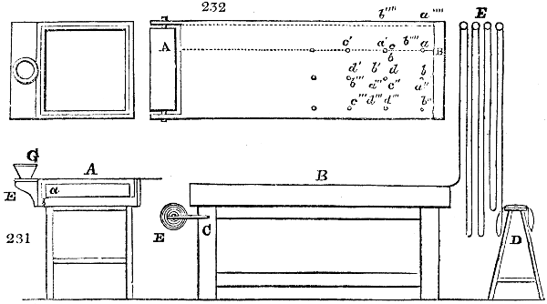
The printing shop is an oblong apartment, lighted with numerous windows at each side, and having a solid table opposite to each window. The table B, fig. 231. is formed of a strong plank of well-seasoned hard wood, mahogany, or marble, with a surface truly plane. Its length is about 6 feet, its breadth 2 feet, and its thickness 3, 4, or 5 inches. It stands on strong feet, with its top about 36 inches above the floor. At one of its ends there are two brackets C for supporting the axles of the roller E, which carries the white calico to be printed. The hanging rollers E are laid across joists fixed near the roof of the apartment above the printing shop, the ceiling and floor between them being open bar work, at least in the middle of the room. Their use is to facilitate the exposure, and, consequently, the drying of the printed pieces, and to prevent one figure being daubed by another. Should they come to be all filled, the remainder of the goods must be folded lightly upon the stool D.
The printer stretches a length of the piece upon his table A B, taking care to place the selvage towards himself, and one inch from the edge. He presents the block towards the end, to determine the width of its impression, and marks this line A B, by means of his square and tracing point. The spreader now besmears the cloth with the colour, at the commencement, upon both sides of the sieve head; because, if not uniformly applied, the block will take it up unequally. The printer seizes the block in his right hand, and daubs it twice in different directions upon the sieve cloth, then he transfers it to the calico in the line A B, as indicated by the four points a b c d, corresponding to the four pins in the corners of the block. Having done so, he takes another daub of the colour, and makes the points a b fall on c d, so as to have at the second stamp a′ b′, covering a b and c′ d′; and so on, through the rest, as denoted by the accented letters. When one table length is finished, he draws the cloth along, so as to bring a new length in its place.
The grounding in, or re-entering (rentrage), of the other colours is the next process. The blocks used for this purpose are furnished with pin-points, so adjusted that, when they are made to coincide with the pin-points of the former block, the design will be correct; that is to say, the new colour will be applied in its due place upon the flower or other figure. The points should not be allowed to touch the white cloth, but should be made to fall upon the stem of a leaf, or some other dark spot. These rentrages are of four sorts:—1. One for the mordants, as above; 2. one for topical colours; 3. one for the application of reds; and, 4., one for the application of resist pastes or reserves. These styles have superseded the old practice of pencilling.
The Perrotine is a machine for executing block-printing by mechanical power; and it performs as much work, it is said, as 20 expert hands. I have seen its operation, in many factories in France and Belgium, in a very satisfactory manner; but I have reason to believe that there are none of them as yet in this country. Three wooden blocks, from 21⁄2 to 3 feet long, according to the breadth of the cloth, and from 2 to 5 inches broad, faced with pear-tree wood, engraved in relief, are mounted in a powerful cast-iron frame work, with their planes at right angles to each other, so that each of them may, in succession, be brought to bear upon the face, top, and back of a square prism of iron covered with cloth, and fitted to revolve upon an axis between the said blocks. The calico passes between the prism and the engraved blocks, and receives successive impressions from them as it is successively drawn through by a winding cylinder. The blocks are pressed against the calico through the agency of springs, which imitate the elastic pressure of the workman’s hand. Each block receives a coat of coloured paste from a woollen surface, smeared after every contact with a mechanical brush. One man, with one or two children for superintending the colour-giving surfaces, can turn off about 30 pieces English per day, in three colours, which is the work of fully 20 men and 20 children in block printing by hand. It executes some styles of work to which the cylinder machine, without the surface roller, is inadequate.
The copper-plate printing of calico is almost exactly the same as that used for printing engravings on paper from flat plates, and being nearly superseded by the next machine, need not be described.
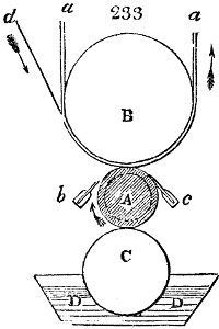
The cylinder printing machine consists, as its name imports, of an engraved copper cylinder, so mounted as to revolve against another cylinder lapped in woollen cloth, and imbued with a coloured paste, from which it derives the means of communicating coloured impressions to pieces of calico passed over it. Fig. 233. will give the reader a general idea of this elegant and expeditious plan of printing. The pattern is engraved upon the surface of a hollow cylinder of copper, or sometimes gun-metal, and the cylinder is forced by pressure upon a strong iron mandrel, which serves as its turning shaft. To facilitate the transfer of the impression from the engraving to the cotton cloth, the latter is lapped round another large cylinder, rendered elastic by rolls of woollen cloth, and the engraved cylinder presses the calico against this elastic cushion, and thereby prints it as it revolves. Let A be the engraved cylinder mounted upon its mandrel, which receives rotatory motion by wheels on its end, connected with the steam or water power of the factory. B is a large iron drum or roller, turning in bearings of the end frames of the machine. Against that drum the engraved cylinder A is pressed by weights or screws; the weights acting steadily, by levers, upon its brass bearings. Round the drum B the endless web of felt or blanket stuff a a, travels in the direction of the arrow, being carried round along with the drum B, which again is turned by the friction of contact with the cylinder A. c represents a clothed wooden roller, partly plunged into the thickened colour of the trough D D. That roller is also made to bear, with a moderate force, against A, and thus receives, by friction, in some cases, a movement of rotation. But it is preferable to drive the roller C from the cylinder A, by means of a system of toothed wheels attached to their ends, so that the surface speed of the wooden or paste roller shall be somewhat greater than that of the printing cylinder, whereby the colour will be rubbed, as it were, into the engraved parts of the latter.
As the cylinder A is pressed upwards against B, it is obvious that the bearers of the trough and its roller must be attached to the bearings of the cylinder A, in order to preserve its contact with the colour-roller C. b is a sharp-edged ruler of gun-metal or steel, called the colour doctor, screwed between two gun-metal stiffening bars; the edge of which wiper is slightly pressed as a tangent upon the engraved roller A. This ruler vibrates with a slow motion from side to side, or right to left, so as to exercise a delicate shaving action upon the engraved surface, as this revolves in the direction of the arrow. c is another similar sharp-edged ruler, called the lint doctor, whose office it is to remove any fibres which may have come off the calico in the act of printing, and which, if left on the engraved cylinder, would be apt to occupy some of the lines, or at least to prevent the colour from filling them all. This lint doctor is pressed very slightly upon the cylinder A, and has no traverse motion.
What was stated with regard to the bearers of the colour trough D, namely, that they are connected, and moved up and down together with the bearings of the cylinder A, may also be said of the bearers of the two doctors.
The working of this beautiful mechanism may now be easily comprehended. The web of calico, indicated in the figure by the letter d, is introduced or carried in along with the blanket stuff a a, in the direction of the arrow, and is moved onward by the pressure of the revolving cylinder A, so as to receive the impression of the pattern engraved on that cylinder.
Before proceeding to describe the more complex calico-machine which prints upon cloth, 3, 4, or 5 colours at one operation, by the rotation of so many cylinders, I shall explain the modern methods of engraving the cylinder, which I am enabled to do by the courtesy of Mr. Locket, of Manchester, an artist of great ingenuity in this department, who politely allowed me to inspect the admirable apparatus and arrangements of his factory.
To engrave a copper cylinder 3 or 4 inches in diameter, and from 30 to 36 inches long with the multitude of minute figures which exist in many patterns, would be a very laborious and expensive operation. The happy invention made by Mr. Jacob Perkins, in America, for transferring engravings from one surface to another by means of steel roller dies, was with great judgment applied by Mr. Locket to calico-printing, so long ago as the year 1808, before the first inventor came to Europe with the plan. The pattern is first drawn upon a scale of about 3 inches square, so that this size of figure being repeated a definite number of times, will cover the cylinder. This pattern is next engraved in intaglio upon a roller of softened steel, about 1 inch in diameter, and 3 inches long, so that it will exactly occupy its surface. The engraver aids his eye with a lens, when employed at this delicate work. This roller is hardened by heating it to a cherry-red in an iron case containing pounded bone-ash, and then plunging it into cold water; its surface being protected from oxidizement by a chalky paste. This hardened roller is put into a press of a peculiar construction, where, by a rotatory pressure, it transfers its design to a similar roller in the soft state; and as the former was in intaglio, the latter must be in relievo. This second roller being hardened, and placed in an appropriate volutory press, is employed to engrave by indentation upon the full-sized copper cylinder, the whole of its intended pattern. The first roller engraved by hand is called the die; the second, obtained from it by a process like that of a milling tool, is called the mill. By this indentation and multiplication system, an engraved cylinder may be had for seven pounds, which engraved by hand would cost fifty or upwards. The restoration of a worn-out cylinder becomes extremely easy in this way; the mill being preserved, need merely be properly rolled over the copper surface again.
At other times, the hard roller die is placed in the upper bed of a screw press, not unlike that for coining, while the horizontal bed below is made to move upon strong rollers mounted in a rectangular iron frame. In the middle of that bed a smooth cake or flat disc of very soft iron, about 1 inch thick, and 3 or 4 inches in diameter, is made fast by four horizontal adjusting screws, that work in studs of the bed frame. The die being now brought down by a powerful screw, worked by toothed wheel-work, and made to press with force upon the iron cake, the bed is moved backwards and forwards, causing the roller to revolve on its axles by friction, and to impart its design to the cake. This iron disc is now case-hardened by being ignited amidst horn shavings in a box, and then suddenly quenched in water, when it becomes itself a die in relievo. This disc die is fixed in the upper part of a screw press with its engraved face downwards, yet so as to be movable horizontally by traverse screws. Beneath this inverted bed, sustained at its upper surface by friction-rollers, a copper cylinder 30 inches long, or thereby, is mounted horizontally upon a strong iron mandrel, furnished with toothed wheels at one of its ends, to communicate to it a movement upon its axis through any aliquot arcs of the circle. The disc die being now brought down to bear upon the copper cylinder, this is turned round through an arc corresponding in length to the length of the die; and thus, by the steady downward pressure of the screw, combined with the revolution of the cylinder, the transfer of the engraving is made in intaglio. This is I believe the most convenient process for engraving, by transfer, the copper of a one-cylinder machine. But when 2, 3, or 4 cylinders are to be engraved with the same pattern for a two, three, or four-coloured machine, the die and the mill roller plan of transfer is adopted. In this case, the hardened roller die is mounted in the upper bed of the transfer press, in such a way as to be capable of rotation round its axis, and a similar roller of softened steel is similarly placed in the under bed. The rollers are now made to bear on each other by the action of the upper screw, and while in hard contact, the lower one is caused to revolve, which, carrying round the upper by friction, receives from it the figured impression in relief. When cylinders for a three-coloured machine are wanted, three such mills are made fac-similes of each other; and the prominent parts of the figure which belong to the other two copper cylinders are filed off in each one respectively. Thus three differently figured mills are very readily formed, each adapted to engrave its particular figure upon a distinct copper cylinder.
Some copper cylinders for peculiar styles are not graved by indentation, as just described, but etched by a diamond point, which is moved by mechanism in the most curious variety of configurations, while the cylinder slowly revolves in a horizontal line beneath it. The result is extremely beautiful, but it would require a very elaborate set of drawings to represent the machinery by which Mr. Locket produces it. The copper is covered by a resist varnish while being heated by the transmission of steam through its axis. After being etched, it is suspended horizontally by the ends, for about five minutes, in an oblong trough charged with dilute nitric acid.
With regard to the two and three-coloured machines, we must observe, that as the calico in passing between the cylinders is stretched laterally from the central line of the web, the figures engraved upon the cylinders must be proportionally shortened, in their lateral dimensions especially, for the first and second cylinder.
Cylinder printing, though a Scotch invention, has received its wonderful development in England, and does the greatest honour to this country. The economy of labour introduced by these machines is truly marvellous; one of them, under the guidance of a man to regulate the rollers, and the service of a boy, to supply the colour troughs, being capable of printing as many pieces as nearly 200 men and boys could do with blocks. The perfection of the engraving is most honourable to our artisans. The French with all their ingenuity and neat-handedness can produce nothing approaching in excellence to the engraved cylinders of Manchester,—a painful admission, universally made to me by every eminent manufacturer in Alsace, whom I visited in my late tour.
Another modification of cylinder printing, is that with wooden rollers cut in relief: it is called surface printing, probably because the thickened colour is applied to a tense surface of woollen cloth, from which the roller takes it up by revolving in contact with the cloth. When the copper cylinders, and the wooden ones, are combined in one apparatus, it has got the appropriate name of the union printing machine.
In mounting three or more cylinders in one frame, many more adjustments become necessary than those described above. The first and most important is that which ensures the correspondence between the parts of the figures in the successive printing rollers, for unless those of the second and subsequent engraved cylinders be accurately inserted into their respective places, a confused pattern would be produced upon the cloth as it advances round the pressure cylinder B, figs. 233, 234.
Each cylinder must have a forward adjustment in the direction of rotation round its axis, so as to bring the patterns into correspondence with each other in the length of the piece; and also a lateral or traverse adjustment in the line of its axis, to effect the correspondence of the figures across the piece; and thus, by both together, each cylinder may be made to work symmetrically with its fellows.
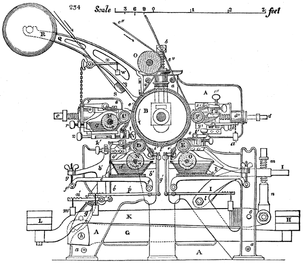
Fig. 234 enlarged (227 kB)
Fig. 234. is a cross section of a four-colour cylinder machine, by which the working parts are clearly illustrated.
A A A is a part of the two strong iron frames or cheeks, in which the various rollers are mounted. They are bound together by the rods and bolts a a a a.
B is the large iron pressure cylinder, which rests with its gudgeons in bearings or bushes, which can be shifted up and down in slots of the side cheeks A A. These bushes are suspended from powerful screws b, which turn in brass nuts, made fast to the top of the frame A, as is plainly shown in the figure. These screws serve to counteract the strong pressure applied beneath that cylinder, by the engraved cylinders D E.
C D E F are the four printing cylinders, named in the order of their operation. They consist of strong tubes of copper or gun-metal, forcibly thrust by a screw press upon the iron mandrels, round which as shafts they revolve.
The first and last cylinder C and F are mounted in brass bearings, which may be shifted in horizontal slots of the frame A. The pressure roller B, against whose surface they bear with a very little obliquity downwards, may be nicely adjusted to that pressure by its elevating and depressing screws. By this means C and F can be adjusted to B with geometrical precision, and made to press it in truly opposite directions.
The bearings of the cylinders D and E are lodged also in slots of the frame A, which point obliquely upwards, towards the centre of B. The pressure of these two print cylinders C and F is produced by two screws c and d, which work in brass nuts, made fast to the frame, and very visible in the figure. The frame-work in which these bearings and screws are placed, has a curvilinear form, in order to permit the cylinders to be readily removed and replaced; and also to introduce a certain degree of elasticity. Hence the pressure applied to the cylinders C and F, partakes of the nature of a spring; a circumstance essential to their working smoothly, on account of the occasional inequalities in the thickness of the felt web and the calico.
The pressure upon the other two print cylinders D and E is produced by weights acting with levers against the bearings. The bearings of D are, at each of their ends, acted upon by cylindrical rods, which slide in long tubular bosses of the frame, and press with their nuts g at their under end upon the small arms of two strong levers G, which lie on each side of the machine, and whose fulcrum is at h (in the lower corner at the left hand). The long arms of these levers G, are loaded with weights H, whereby they are made to press up against the bearings of the roller D, with any degree of force, by screwing up the nut g, and hanging on the requisite weights.
The manner in which the cylinder E is pressed up against B, is by a similar construction to that just described. With each of its bearings, there is connected by the link k, a curved lever I, whose fulcrum or centre of motion is at the bolt l. To the outer end of this lever, a screw, m, is attached, which presses downwards upon the link n, connected with the small arm of the strong lever k, whose centre of motion is at o. By turning therefore the screw m, the weight L, laid upon the end of the long arm of the lever K (of which there is one upon each side of the machine), may be made to act or not at pleasure upon the bearings of the cylinder E.
In tracing the operation of this exquisite printing machine, we shall begin with the first engraved cylinder C. Its bearings or bushes shift, as was already stated, in slots of the frame A. Each of them consists of a round piece of iron, to which the end of the screw c is joined, in the same way as at d, in the opposite side. In each of these iron bearings, a concave brass is inserted to support the collar of the shaft, and in a dovetailed slit of this brass, a sliding piece is fitted, upon which a set or adjusting screw in the iron bearing acts, and which, being forced against the copper cylinder C, serves to adjust the line of its axis, and to keep it steady between its bearings, and true in its rotatory motion. Upon the iron bearing a plate is screwed, provided with two flanges, which support the colour trough q, and the colour roller M. This trough, as well as the others to be mentioned presently, is made of sheet copper in the sides and bottom, and fixed upon a board; but its ends are made of plates of cast copper or gun-metal to serve as bearings to the colour roller M. The trough and its roller may be shifted both together into contact with the printing cylinder C, by means of the screw r. Near s, seen above the roller, C, and t below it, are sections of the two doctors, which keep the engraved cylinders in sound working condition; the former being the colour doctor, and the latter the lint doctor. Their ends lie in brasses, which may be adjusted by the screws u and V, working in the respective brackets, which carry their brasses, and are made fast to the iron bearings of the cylinder.
The pressure of the colour doctor is produced by two weights w (see high up on the frame work), which act on a pair of small levers x, (one on each side of the machine,) and thus, by means of the chains, tend to lift the arms y, attached to the end axles of the doctor. The pressure of the lint doctor upon the cylinder C, is performed by the screw z, pressing upon an arm which projects downwards, and is attached to the axle of that doctor.
The bearings of the second printing cylinder D, consist at each end of a mass of iron (removed in the drawing to show the mechanism below it), which shifts in the slanting slot of the frame A. In each of these masses there is another piece of iron, which slides in the transverse direction, and may be shifted by the adjusting screw a′ fixed to it, and working in a nut cast upon the principal bearing above described. To the inner bearings, which carry the brasses in which the shaft lies, are screwed the two curved arms b′ b′ to which are attached the bearings, &c., for the colour trough, and the doctors. In these brasses there are also dovetailed pieces, which slide and are pressed by set screws furnished with square heads in the iron secondary bearings, which serve, as before said, to adjust the printing cylinder in the line of its axis, while other screws adjust the distance of the cloth upon which the second colour is printed, and the line of contact with the cylinder B.
N, is the colour roller of D, and d′ the colour trough, which rests by its board upon the lever e′; whose centres of motion f′, are made fast to the curved arms b′, fixed at the bearings of the cylinder, and whose ends are suspended by screws g′; whereby the colour roller N, may be pressed with greater or less force to the cylinder D. h′ and i′ are the two doctors of this cylinder; the former being the colour, the latter the lint doctor. They rest, as was said of the cylinder C, in brasses which are adjustable by means of screws, that work in the studs or brackets by which the brasses are supported. These brackets must of course be screwed to the secondary bearing-pieces, in order that they may keep their position, into whatever direction the bearings may be shifted. k′ and l′ are these set screws for the colour and lint doctors. The pressure of the former upon the cylinder D, is produced by weights m′, acting upon levers n′, and pressing by rods or links o′, upon arms attached to each end of the axis of the doctor. (See the left hand side of the figure near the bottom). The lint-doctor i′, is pressed in a similar way at the other side upon the cylinder D, by the weights acting upon levers p′, and by rods q′ upon arms fixed at each end of the axis of the doctor.
The bearings of the third printing cylinder E, are of exactly the same construction as that above described, and therefore require no particular detail. The lint doctor s, is here pressed upon the engraved cylinder by screws t′, working in the ends of studs or arms fixed upon each end of the axis of the doctor, and pressing upon flanges cast upon the brackets in which the brasses of the doctor’s axis lie, which are made fast to the bearings of the cylinder E.
The bearings of the fourth copper cylinder F, are also constructed in a similar way. Each consists of a first bearing, to which is joined the end of the screw d, by which it is made to slide in a slot of the frame. Another bearing, which contains the brass for the shaft of the cylinder, can be shifted up and down in a transverse direction by a screw z′, of the second bearing, working in a nut cast upon the first bearing. To this secondary bearing, plates are made fast by the screws v′ v′ to the inside, to carry the studs or brackets of the doctors x′ and y′. In the brasses of the cylinder shaft, dovetailed pieces are made to slide, being pressed by set screws w′, against the engraved cylinder F, similar to what has been described for adjusting the cylinders to one another. This cylinder has no separate colour roller, nor trough, properly speaking, but the colour doctor y′ is made concave to serve the purpose of a trough in supplying the engraved lines of the cylinder with colour. With this view the top plate of the doctor is curved to contain the coloured paste, and it is shut up at the ends by pieces of wood made to fit the curvature of the doctor. Its pressure against the engraved surface is produced by weights a′′, acting at the ends of arms b′′, attached to the ends of the axis of the doctor. The pressure of the lint doctor x′ is given by screws c′′, working in arms attached to the ends of the axis of the doctor, and pressing upon the flanges d′′, cast upon the brackets which carry the brasses for the axis of the doctor. These brasses are themselves adjustable, like those of all the other cylinders, by set screws in the brackets, which work in the nuts formed in the brasses.
e′′ e′′, is the endless web of felt stuff which goes round the cylinder B, and constitutes the soft elastic surface upon which the printing cylinders C, D, E, and F exercise their pressure. This endless felt is passed over a set of rollers at a certain distance from the machine, to give opportunity for the drying up of any colouring paste which it may have imbibed from the calico in the course of the impressions. In its return to the machine in the direction of the arrow, it is led over a guide roller o, which is thereby made to revolve. Upon the two ends of this, and outside of the bearings which are fixed upon the tops of the frame A, are two eccentrics, one of which serves to give a vibratory traverse movement to the colour doctors s′, h′, and r′ of the three cylinders, C, D, and E whilst the other causes the colour doctor y′ of the cylinder F, to make lateral vibrations.
Q is one of a pair of cast-iron brackets, screwed on at the back of the side-frames or cheeks A A, to carry the roller filled with white calico R, ready for the printing operations. Upon the end of the shaft whereon the calico is coiled, a pulley is fixed, over which a rope passes suspending a weight in order to produce friction, and thereby resistance to the action which tends to unwind the calico. In winding it upon that and similar rollers, the calico is smoothed and expanded in breadth by being passed over one or more grooved rods, or over a wooden bar S, fig. 235. the surface of which is covered with wire, so as to have the appearance of a united right and left-handed screw. By this device, the calico, folded or creased at any part, is stretched laterally from the centre, and made level. It then passes over the guide-roller o, where it comes upon the surface of the felt e′′ e′′, and thence proceeds under its guidance to the series of printing cylinders.
Three and four-colour machines, similar to the above, are now at work in many establishments in Lancashire, which will turn off a piece of 28 yards per minute, each of the three or four cylinders applying its peculiar part of the pattern to the cloth as it passes along, by ceaseless rotation of the unwearied wheels. At this rate, the astonishing length of one mile of many-coloured web is printed with elegant flowers and other figures in an hour. When we call to mind how much knowledge and skill are involved in this process, we may fairly consider it as the greatest achievement of chemical and mechanical science.