F. (continued 3)
Reading edition
Can flax be prepared without retting?—The waste of time and labour in the steeping of flax; the dyeing of the fibres consequent thereon, which must be undone by bleaching; the danger of injuring the staple by the action of putrescent water; and, lastly, the diminished value of flax which is much water-retted, are all circumstances which have of late years suggested the propriety of superseding that process entirely by mechanical operations. It was long hoped, that by the employment of breaking machines, the flax merely dried could be freed from its woody particles, while the textile filaments might be sufficiently separated by a subsequent heckling. Experience has, however, proved the contrary. The machines, which consisted for the most part of fluted rollers of iron or wood, though expensive, might have been expected to separate the ligneous matter from the fibres; but, in the further working of the flax no advantage was gained over the water-retting process.
1. Unretted flax requires a considerably longer time for breaking than retted, under the employment of the same manipulations.
2. Unretted stalks deliver in the breaking and heckling a somewhat greater product than the same weight of flax which has been retted; but there is no real advantage in this, as the greater weight of the unretted flax consists in the remainder of ligneous or glutinous matter, which being foreign to the real fibre, must be eventually removed. In the bleaching process, the water and the alkaline lyes take away that matter, so that the weight of the bleached fibre is not greater from the unretted than the retted flax.
3. The parting of the fibres in the unretted stalks is imperfectly effected by the heckling, the flax either remains coarser as compared with the retted article, and affords a coarser thread, or if it be made to receive greater attenuation by a long continued heckling, it yields incomparably more torn filaments and tow.
4. The yarn of unretted flax feels harder, less glossy, and rougher; and, on account of these qualities, turns out worse in the weaving than the retted flax. Nor is the yarn of unretted flax, whether unbleached or bleached, in any degree stouter than the yarn of the retted flax.
5. Fabrics of unretted flax require for complete bleaching about a sixth less time and materials than those of the retted. This is the sole advantage, but it is more than counterbalanced by the other drawbacks above specified.
In Mr. Wordsworth’s improved apparatus for heckling flax and hemp, a succession of stricks is subjected to the operation of several series of revolving heckles of different degrees of fineness, for the purpose of gradually separating or combing the long fibres, and dressing them smooth; while at the same time, the tow or entangled refuse portions of the material taken off from the stricks by the heckle points are removed from the heckles by rotatory brushes and rollers covered with wire cards, and discharged into suitable receivers, whence it may be taken to a carding engine, to be worked in the ordinary way.
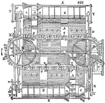
Fig. 426 enlarged (103 kB)
The accompanying figures represent in plan and section, the heckling machine which is made double, for the purpose of allowing two series of stricks of flax to be acted upon at one time. Fig. 426. is a horizontal view of the machine; fig. 427. is an end view, the whole being represented in working order, and the respective letters of reference pointing out corresponding parts of the machine.
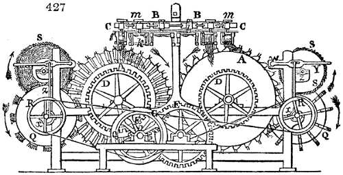
A A are two large barrels or drums, upon the surfaces of which are fixed longitudinally several series of brass ribs a, b, c, d, e, f, g, h, i, holding heckle points. These ribs are placed at small distances apart round the barrels, all the heckle points standing radially from the axes, and the barrels are mounted upon axles supported by pedestals, with plummer blocks bearing on the rails of the end frames. B B, are two horizontal wheels or pulleys turning upon vertical shafts, which pulleys conduct an endless chain C C C C, carrying the holders, whereon the stricks of flax or other material intended to be heckled are suspended.
At one end of the axle of each of the barrels a toothed wheel D D, is made fast, and these are connected by a similar wheel E, and a pinion F, fig. 427., the latter being fixed upon the axle of the driving rigger G.
The power of a steam engine, or any other first mover, being applied by a band and rigger, or otherwise to the axle of G, the pinion F, is driven round, which, being in geering with the toothed wheels E and D D, causes the heckle barrels A A to revolve simultaneously in opposite directions, as shown by the arrows in fig. 427.
The stricks of flax intended to be operated upon are severally confined between pairs of clamps k, fastened together, which clamps, with the stricks, are then suspended in their respective holders H H, attached to the endless chain C: the lower portion of the flax hanging down for the purpose of being acted upon by the rotatory heckles, while the upper portions are turned up in loops and confined by spring levers attached to each carrier.
The respective holders of the clamps consist of a forked frame, with hooks at the lower parts of their arms, which receive the ends of the clamps k, that confine the strick of flax. From the upper part of each forked frame, a perpendicular pin extends, which pins when inserted into the sockets l l l, in front of the chain, form axles for the frames to turn upon at certain periods of the operation.
On the upper end of each pin, a small arm or tappet piece m, fig. 427., is fixed, standing at right angles to the face of the forked frame of the holder H. Those tappets as the endless chain conducts the holders along at certain periods, come in contact with stationary pins or wipers n n, fixed to the guide rails o, on which the chain C slides; and these wipers acting against the tappets as they pass, cause the holders to be turned round at those periods for the purpose of bringing the reverse side of the strick of flax on to the heckle points.
Let it now be supposed, that all the holders connected to the endless chain have been furnished with stricks of flax, or other material to be heckled, and that the barrels A A, are put in motion in the way described, revolving in the direction of the arrows shown in fig. 427. A pinion on the end of the axles of one of the barrels A, will drive a train of toothed geer J K L M and N, on the axle of the latter, of which there is a bevelled pinion taking into a bevelled wheel, turning horizontally at the lower end of the perpendicular shaft of one of the chain pulleys. It will hence be perceived that as the barrels go round, such rotatory motion will be communicated to the pulley B, as will cause it to drive the chain C forward, and by that means conduct the several stricks of flax progressively along the barrel.
When each successive holder, with its strick of flax or other material, is brought to the part z, fig. 426., the fibres come in contact with the rotatory barrel, and first strike upon the series of coarse heckles a a, placed upon an inclined or conical surface of the barrel, by which means the lower ends of the flax in each strick are first acted upon; and as it advances, the upper part, and ultimately the whole length of the long fibres of the suspended strick are gradually brought on to the heckles, which progressive operation prevents the long fibres from being broken, and causes a smaller quantity of tow to be produced than is usually taken off in any of the ordinary modes of heckling.
After the strick of flax or other material has been carried by the travelling chain past the first inclined or conical surface a, of the heckling barrel, it then comes upon the cylindrical part b, of the barrel, which is also furnished with coarse heckles that penetrate and comb down the whole pendant lengths of the fibres. But in order that both sides of the strick of flax may be equally operated upon, the holder is now to be turned round upon its pin or pivot, which movement is effected by one arm of the lever or tappet m, (as the carrying chain moves onward), coming against the stationary pin or wiper n, which changes the position of the holder, as shown at p, in the horizontal view fig. 426.
The under part of the guide rail o, upon which the chain slides, is at this part cut away, for the purpose of allowing the holder to turn round horizontally; and a pin or projection at the under side of the guide rail, as the chain continues moving, acts against the side of the carrier frame, and forces it into a position parallel with the chain. The other side of the strick of flax is by these means brought on to the heckles of the second inclined or conical surface of the barrel at c; and the travelling chain proceeding onward, the fibres of the material are in succession passed over and combed by the heckles of increasing fineness, d, e, and f, on the cylindrical part of the revolving barrel, until the strick having arrived at the second wiper n, the frame or holder is at q, turned round as before, and the reverse side of the strick, or that first operated upon by the heckles a and b, is brought progressively on to the heckles of increasing fineness, g, h, and i; and having passed the last series of rotatory heckles, the holders are in succession to be removed from the machine, the material having been sufficiently dressed.
The clamps of the holders are now opened by the attendant, and the stricks of flax or other material are taken out, and again placed between the clamps in reversed positions, in order that the other ends of the fibres may be operated upon. The clamps, with the stricks, are then suspended again in the holders, the uncombed ends of the fibres hanging down upon the heckle barrel.
In order to avoid interrupting the continual operation of the machine, it is proposed that the strick, on its second introduction, shall be placed in the holders on the opposite side at y, which is one of the reasons for constructing a double machine, and the strick being thence carried along by the travelling endless chain in the way already described, the fibres will be first brought under the operation of the coarse heckles on the inclined or conical surface of the second revolving barrel, and then of the other heckles increasing in fineness on the cylindrical part of the barrel, until having reached the end, as in the former instance, the fibres of the flax may be considered to be sufficiently dressed, and may then be withdrawn.
It may be necessary here to remark, that as different kinds and qualities of material will require different degrees of working by the heckles, this can be effected by varying the comparative speeds of the travelling holders and the heckle barrels. These comparative speeds, it will be perceived, depend upon the diameters of the wheels and pinions by which the pulley B is driven from the rotation of the heckle barrel. These wheels and pinions are therefore intended to be removed and changed for others of different diameters, as circumstances may require. It will be perceived that the faster the stricks travel through the machine compared to the rotatory speed of the heckle barrels, so much the less will the material be acted upon by the rotatory heckles; but as different qualities of material must be differently operated upon, according to circumstances, it is impossible to set out any definite speeds or proportions of speed: that will, however, be readily perceived by competent workmen when working at the machine.
In the process of opening the fibres of the material by the rotatory heckles, a quantity of short or loose fibres, as tow, will be taken off the stricks by the heckle points, and will remain adhering to the barrel between the points of the heckles: in order, therefore, to remove this tow, or other loose entangled materials from the heckles, several series of brushes, or blocks, with bristles, are affixed longitudinally to rotatory barrels Q Q.
These brush barrels are mounted parallel to the heckle barrels upon axles, supported in plummer blocks affixed to brackets extending from the end frames of the machine. Those parts of the brush barrels which are opposite to the cylindrical portions of the heckle barrel are cylindrical, and those parts which are opposite to the bevels are contra-bevelled, or made as frustums of cones reversed, or in an opposite angle, as r, s, so as to run parallel to the inclined surfaces of the heckle barrels a and c.
Upon the periphery of these barrels Q Q, ribs or blocks, with bristles or brushes, are fixed longitudinally, at suitable distances apart, the bristles all standing radially from the axle, and taking into the points of the heckles.
Rotatory motions are given to the brush barrels Q Q, by bands passing from the riggers at G, over pulleys R R, fixed at the end of each of the axles of the brush barrels. Hence, it will be perceived, that the barrels Q Q will revolve in opposite directions to the heckle barrels, and with sufficient speed to enable the brushes to pass through between the points of the heckles, and in so doing, to remove the tow or other loose matter therefrom.
The tow or other loose fibrous material collected upon the brushes is transferred thence on to wire cards placed round the periphery of the barrels S S, which barrels are mounted upon axles parallel to the brush rollers, and turn in plummer blocks upon brackets, extending from the end frames of the machine.
These barrels are cylindrical, and covered with sheets of wire cards at those parts which are opposite to the cylindrical portions of the brush barrels, but those portions of the barrel S, which are opposite to the bevelled points r and s, of the brush barrels, are bevelled or made conical at t u, to fit or correspond with the inclined surfaces r and s; these are covered with sheets of wire card also.
Rotatory motions are communicated to the card barrels S S, by bands from the pulley T, fixed on to the side of the toothed wheel M, (see fig. 427.) which band drives similar pulleys V V, mounted upon studs fixed in the end frame. Upon the side of each of these pulleys V V, a pinion t is fixed, which pinion takes into the teeth of the wheel W, on the end of the axle of each of the card barrels S S; by which means such slow motions are given to the barrels S, as will allow the brushes of the barrels Q to comb off, and deposit the tow or other fibrous material upon the wire cards as they revolve, and from whence it is to be removed by a doffing comb, and let fall into any convenient receptacle below, in the same way as in ordinary carding engines.
The doffing combs, X X X, are formed to the shape of the card barrels, and are attached to straight bars extending along the machine on both sides, which are supported at their extremities by levers Y Y, vibrating upon fulcrum pivots at w w. To these levers perpendicular rods Z Z are connected by joints, and the lower end of each of these rods is attached to an eccentric disk, roller or crank x x, on the axle of the brush barrel; whence it will be perceived that by the rotation of the eccentrics x, the levers Y will be made to vibrate and strike off, or doff the tow or other material from the card barrels, in a similar manner to the operations of the doffing comb of an ordinary carding engine.
Mr. Evans’ patent improvements in machinery for preparing and dressing flax and hemp apply, first, to the operation of scutching, swingling, or beating away the boom or woody particles of the rind which covers the flax, or hemp, in its rough state; and, secondly, to the subsequent operation of heckling, combing, or opening of the fibres of the material preparatory to spinning it into yarns.
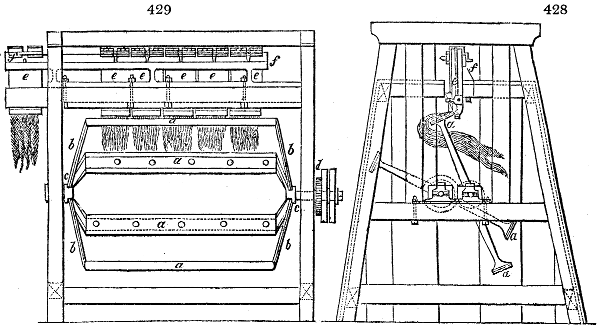
Fig. 428. represents the scutching or swingling machine, in different positions. Fig. 428. is an end view of the machine in operation; fig. 429. is a front view of the same. The essential parts of the machine, and those in which the invention especially consists, are two pairs of revolving beaters or scutchers, each formed by long ribs or blades mounted upon arms. The blades of the beaters a a, may be made of ribs of hard wood, or other suitable material, broad but thin, and slightly rounded on their edges, to prevent their cutting the fibres of the flax or hemp when they strike it. The two blades are placed parallel to each other, and mounted upon a hexagonal frame, the arms b b inclining or forming obtuse angles with the blades, and from the middle of the arms short axles c c, extend, upon which the beaters revolve.
The axles of both pairs of beaters are mounted in plummer boxes, bearing upon horizontal rails at the ends of the machine, as shown in fig. 428., and are at such distance apart as will allow of the arms and the beaters of each pair passing alternately within those of the other pair as they revolve in opposite directions, which they are enabled to do without coming in contact, in consequence of the inclination of the arms.
On the axle at one end of each pair of beaters a toothed wheel d, is affixed, and these wheels being of similar diameters, and taking into each other, cause the beaters to revolve with similar speed in opposite directions, rotatory motion being given to them by a band and rigger fixed upon one of the axles; and in order that the beaters in revolving may not come in contact as they pass, the positions of the two pairs are so arranged that the blades of one shall be in a perpendicular situation, while those of the other are horizontal.
The rind of the flax or hemp having been previously broken by any of the ordinary modes of performing that operation, small bunches or stricks of the material are spread out, and their ends confined between the jaws of clamps or holders.
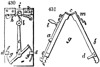
These clamps or holders differ considerably from the clamps which are commonly used. I shall therefore particularly describe their construction, before showing them in operation. Fig. 430. and 431. are views of the clamp in two different positions; a and b are two boards united together by a hinge c, at top, which of course allows them to shut and open. The lower parts, forming the jaws of the clamps, are made with teeth or indentations, between which parts the ends of the flax or hemp are securely held when the clamps are brought together; d d, are two pieces projecting from the board b, at the end of each of which is an eye shown by dots, and at the back of the board a, (see fig. 430.,) there is a double armed lever e, turning upon a fixed pin f, which lever carries two circular wedges g g. These wedges pass into the eyes of the pieces d d, when the clamps are closed, and hold them fast. There is a segment ratchet h, at the upper part of the board a, which turns upon a stud i, and is pressed downward by a spring k. This ratchet receives the end of the lever e, and consequently keeps the circular wedges firm in the eyes, which hold the clamps securely together, and prevents their opening by the shaking of the machine.
When it is required to open the clamps, the ratchet h must be raised, and the lever e pushed aside by its handle l, which draws the circular wedges f from the eyes of the pieces d d, and the boards of the clamps immediately separate. For the convenience of suspending the holders in the machines, a piece of sheet iron m, is bent at right angles, and fastened to the back of the board b, as seen in fig. 431., forming a groove by means of which the holders are enabled to slide into the machine and hang there.
These clamps or holders are, when charged with the material, placed in the scutching machine, as shown at e e e in figs. 428. and 429., bearing upon the edge-rail or bar f. The beaters are now made to revolve in the manner already described, by which the edges of the blades will strike against the pendent stricks of flax or hemp alternately on each side, and beat off, scutch or swingle the boom from the material, and render it fit for the operation of heckling which is to follow.
The whole machine is encased with boards, to prevent the inconvenience arising from dust, and an apparatus might be adapted with a blower to conduct away the dust created by the machine, and to discharge it out of the building.
In introducing these stricks of flax or hemp into the machine, the holder is placed upon the projecting end of the bar or edge-rail f, and is thence slidden into the machine; and after the material has been sufficiently scutched or swingled, the holders with the stricks are removed through the top of the machine, and others successively introduced at the end, and pushed along the rail.
If, however, it should be thought desirable, the stricks may be progressively carried through the scutching machine, and delivered into a similar edge-rail in the heckling machine, there to be operated upon in the way about to be described, by which means the whole process of scutching and heckling may go on without interruption.
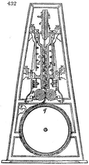
Fig. 432. represents the heckling or combing machine by which the fibres of the material are to be opened, and the tow removed. It is a transverse section, taken nearly through the middle, in a vertical direction. Perpendicular standards form the ends of the machine, which are connected together by longitudinal rods or bars secured by nuts. The heckle points intended to act upon the flax are mounted in the frames a, b, c, and d, and the stricks of flax held in the clamps e, e, e, as described, are suspended from the bar or edge-rail extending through the machine.
In order to render the principles of this machine and its mode of working evident, it may be desirable to show in an abstract form the manner in which the heckles are brought into operation upon the flax, and for this purpose two diagrams are delineated in figs. 433, 434.
Suppose two sets of combs or heckle points be mounted upon frames a and b, as in these figures, each frame being moveable by means of cranks c, c, and d, d, connected in such manner that they both turn with the same speed in opposite directions, it is evident that every part of the frames and combs will move in circles corresponding to those described by the cranks; the points of the combs travelling in the directions of the arrows, and in circles represented by dots.
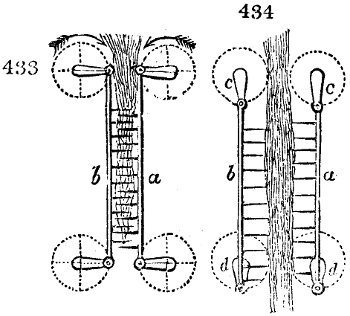
During this movement, whilst performing the first descending quarter of the circle, the cranks bring the frames together as in fig. 433. They begin after this to separate in describing the second descending quarter, and come to the position fig. 434., when, continuing to revolve, they move further from each other in describing the first ascending quarter of the circle, and arrive at the position where the distance is the greatest; lastly, they describe the second ascending quarter returning to the third position. If, therefore, a strick of flax be suspended between the two sets of combs as in fig. 433., and the rotatory motion be continued for a sufficient length of time, the flax will be combed in the whole length which is submitted to the actions of the combs, although the points severally have only operated in very small space.
Such a system of combs or heckles would make a very good and simple heckling engine, if it were not for the inconvenience experienced by the points dragging some of the fibres with them when withdrawing from the flax, which would produce a great waste of material; and to obviate this it would be necessary to introduce some contrivance for clearing the points, which must be attended with considerable complication. The plan, however, of the present improved engine, affords the means of producing the same effect by more simple and efficient means.
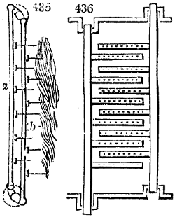
There are two series of combs, see fig. 435., attached to two movable frames represented at a and b. Each frame is formed by vertical bars a b, with lateral branches or arms, which carry the heckle points. The branches or arms are parallel, and at equal distances apart, but fixed in such positions in each frame that they may occupy the intervening space when the frames are brought together as fig. 436. The frames are put in motion by means of revolving cranks to which they are attached, as shown in fig. 436., and when the cranks turn upon their axes, the branches of one frame pass between those of the other without touching. This forms what may be called a set of combs; but one of the improved machines contains two such sets, the points of the combs of one set being opposed to the points of the combs in the other set.
The way in which the series of combs that compose one set act upon the flax, is shown in the side view, fig. 435. When the cranks are nearly vertical, the points of both frames are away from the flax, but as the cranks move round in the direction of the arrows, the frames come into another position, and it is then that the points or heckles of one of the frames a, begin to penetrate the flax, and descending they comb or divide its fibres. The rotation of the cranks continuing, the two frames a and b come into the position shown at fig. 435., the points of the frame a, withdrawing from the flax, and those of the frame b, approaching and pushing the fibres off from the former, which are now combed by the descending stroke of the points.
It will hence be perceived that as the combs of the frame a and b, respectively advance, they will push forward the whole of the strick of flax, and render it impossible for the fibres to be raised and entangled, as each frame in advancing clears the fibres from the points which preceded it.
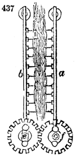
A single set, however, of such combs or heckles acting only on one side of the flax, would but imperfectly perform the operation of opening its fibres; it is therefore necessary, in order to accomplish the desired object in the most effectual way, that two such sets of combs or heckles should be brought to act on opposite sides of the strick of flax, which may be done in the manner shown in the figures. The cranks of the two opposite sets of comb-frames or heckles a, b, and c, d, are connected by a pair of toothed wheels e, f, as fig. 437., or by four toothed wheels, by which the heckles are actuated at once, the two sets moving in opposite directions, but with similar speeds, and the combing or heckling of the material will go on in the way shown in the figure last indicated.
Thus far I have considered only two frames of combs or heckles constituting a set, as acting upon each side of the strick of flax; but in order to perform a greater quantity of work, several sets may be mounted in one machine, working alongside of each other, extending over the breadth of the machine. The combs may then be supported upon three frames, of which the middle one may have branches or arms extending upon both sides, and the other two frames branches extending inwards only. To drive the frames so arranged they must be connected to treble cranks.
Such is the principle of the improved machine for combing or heckling, exhibited in the several figures of which I now proceed to describe the particular construction. The machine or engine, fig. 432., has four sets of combs, acting both at the back and front of the flax; a b are the front set of combs, and c d, the back set of combs; e e e, are the clamps holding the stricks of flax previously scutched, which clamps hang upon the edge-rail. The comb frames are attached at top and bottom to the cranks g g, which are all connected by toothed geer, and driven by a band and rigger.
The combs or heckles being put in motion in the way described, act upon the suspended stricks of flax, and upon their fibres, as explained; which stricks are progressively conducted through the machine by their clamps sliding upon the edge-rail through the agency of the endless chain, to which the clamps are severally attached, by a hook falling into one of the links. The chain is driven by a spur wheel upon the axle of a bevel wheel, which receives a slow rotatory motion through a bevel pinion on the axis of a similar wheel, actuated by another pinion on the end of the upper crank axle. By these means, clamps, with the stricks of flax placed on the edge-rail, are slowly carried through the machine, when the flax will be gradually acted upon first by heckle points of a coarse kind, set wide apart, and ultimately by finer points set near together; after which, the clamp with the strick of flax is discharged from the machine, at the reverse end of the edge-rail. But should the workman neglect to remove the holder or clamp, when it arrives at the end of the rail, the machine would be stopped by means of a jointed lever, having a fork at its end, which pushes the band from the fast rigger on to the loose one, and throws off the driving power.
As the combs or heckles, in acting upon the flax to divide its fibres, tear parts of the fibres, and reduce them into tow, the downward motion of the heckles brings the tow with them out of the flax, which is deposited between two fluted rollers p p, fig. 432., and is by them conducted down to the large drum q, where it becomes lapped in two endless sheets round the periphery of the drum; the one of coarse tow, the other of fine, the adhesion being assisted by a pressing roller r; and when a quantity of the tow has been thus accumulated round the periphery of the drum, it may be removed thence by cutting it off in sheets. The fluted rollers, and also the large drum, are driven by geer bands.
After the strick of flax has been thus carried through the scutching machine or the heckling machine, the jaws of the clamps are to be opened, the ends of the flax reversed, and the strick again confined in the clamps, so that the other end of the strick may be operated upon in a similar way. In order to prevent any part of the flax from attaching itself to the branches of the movable frames, each frame is furnished with a shield or guard of polished iron or brass plate, which covers a part of the combs and the heads of the screws by which they are fixed to the branches. When the plate metal is bent into the form of a shield, it is slipped on to the branches of the heckle frames, and is sufficiently elastic to hold fast.
But it is to be observed, that the edges of the shields are to vary in the extent of their projection according to the situation in which they are to be placed; those which are to shield the upper branches of heckles are to project but little, so as to leave the points uncovered and free to enter the strick of flax; but the shields of the lower heckles are to project considerably over the points, to prevent them from penetrating too far into the fibres, which is so contrived for the purpose of facilitating the falling of the tow, which would otherwise be with difficulty removed from the lower combs, were it thrust upon the whole length of the points.
It being advantageous that each strick of flax should be combed near the lower extremities before the middle is acted upon, it is necessary, in order to obtain this effect, to remove some of the points of the combs in the upper branches. By these means, the operation of the heckles upon the flax begins and proceeds gradually, and ceases at the opposite extremity of the machine in the same gradual way, which is very advantageous in clearing completely the flax from the tow.
IV. Flax spinning.—If we compare flax with other spinning materials, such as wool and cotton, we shall find it to possess several characteristic properties. While cotton and wool are presented by nature in the form of insulated fibres, the former requiring merely to be separated from its seeds, and the latter to be purified from dirt and grease before being delivered to the spinner, flax must have its filaments separated from each other by tedious and painful treatment. In reference to the spinning and the subsequent operations, the following properties of flax are influential and important:—
1. The considerable length of the fibres, which renders it difficult, on the one hand, to form a fine, level, regular thread, on the other, gives the yarn a considerably greater tenacity, so that it cannot be broken by pulling out the threads from each other, but by tearing them across.
2. The smooth and slim structure of the filaments, which gives to linen its peculiar polished aspect, and feel so different from cotton, and especially from woollen stuffs, unless when disguised by dressing. The fibres of flax have no mutual entanglement, whereby one can draw out another as with wool, and they must therefore be made adhesive by moisture. This wetting of the fibres renders them more pliant and easier to twist together.
3. The small degree of elasticity, by which the simple fibres can be stretched only one twenty-fifth of their natural length before they break, while sheep’s wool will stretch from one-fourth to one half before it gives way.
Good flax should have a bright silver gray or yellowish colour (inclining neither to green nor black); it should be long, fine, soft, and glistening, somewhat like silk, and contain no broad tape-like portions, from undissevered filaments. Tow differs from flax in having shorter fibres, of very unequal length, and more or less entangled. Hemp agrees in its properties essentially with flax, and must be similarly treated in the spinning processes.
The manufacture of linen and hemp yarn, and the tow of either, may be effected by different processes; by the distaff, the hand-wheel, and spinning machinery. It will be unnecessary to occupy the pages of this volume with a description of the first two well known domestic employments. I shall therefore proceed directly to describe the last method, or
Spinning of Flax by Machinery.—This branch of manufacture has been much more recently brought to a practical state than the spinning of cotton and wool by machines, of which the cause must be sought for in the nature of flax as above described. The first attempts at the machine spinning of flax, went upon the principle of cutting the filaments into short fragments before beginning the operation. But in this way the most valuable property of linen yarn, its cohesive force, was greatly impaired; or these attempts were restricted to the spinning of tow, which on account of its short and somewhat tortuous fibres, could be treated like cotton, especially after it had been further torn by the carding engine. The first tolerably good results with machinery seem to have been obtained by the brothers Girard at Paris, about the year 1810. But the French have never carried the apparatus to any great practical perfection. The towns of Leeds in Yorkshire, of Dundee in Scotland, and Belfast in Ireland, have the merit of bringing the spinning of flax by machines into a state of perfection little short of that for which the cotton trade has been so long celebrated.
For machine spinning, the flax is sometimes heckled by hand, and sometimes by machinery. The series of operations is the following:—
1. The heckling.
2. The conversion of the flax into a band of parallel rectilinear filaments, which forms the foundation of the future yarn.
3. The formation of a sliver from the riband, by drawing it out into a narrower range of filaments.
4. The coarse spinning, by twisting the sliver into a coarse and loose thread.
5. The fine spinning, by the simultaneous extension and twisting of that coarse thread.
The spinning of tow requires a different treatment: we shall first treat of the heckling of flax by machines; and secondly, of the mechanical spinning of flax. The mechanical carding and spinning of tow are very similar to those of cotton; which see. Though machine heckling be far from perfect, yet the tow it throws off can be spun into very good yarn by machines, while it would afford very indifferent yarn to the hand spinner.
All heckle machines have this common property, that the flax is not drawn through them, as in working by hand, but on the contrary, the system of heckles is moved through the flax properly suspended or laid. Differences exist in the shape, arrangement, and movements of the heckles, as also in regard to the means by which the adhering tow is removed from them. The simplest and most common construction is to place the heckles upon the surface of a horizontal cylinder, while the flax is held either by mechanical means or by the hand during its exposure to the heckle points. Many machines have been made upon this principle. It is proper in this case to set the heckle teeth obliquely in the direction in which the cylinder turns, whereby they penetrate the fibres in a more parallel line, effect their separation more easily, and cause less waste in torn filaments. To conduct the flax upon the cylinders, two horizontal fluted rollers of iron are employed, which can be so modified in a moment by a lever as to present the flax more or less to the heckling mechanism. The operator seizes a tress lock of flax with her hand and introduces it between the fluted rollers, so that the tips on which the operation must begin, reach the heckles first, and by degrees the advancing flax gets heckled through two-thirds or three-fourths of its length, after which the tress or strick is turned, and its other end is subjected to the same process. By its somewhat rapid revolution the heckle cylinder creates a current of air which not only carries away the boomy particles, but also spreads out the flax like a sheaf of corn upon the spikes, effecting the same object as is done by the dexterous swing of the hand. The tow collects betwixt the teeth of the heckle, and may, when its quantity has become considerable, be removed in the form of a flock of parallel layers.
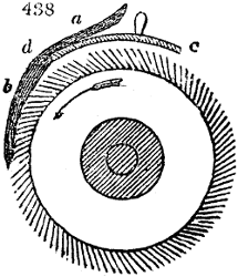
The essential parts of such a construction will be understood from fig. 438., though the fluted rollers are absent. The flax a, b, is held by the hand, or in a kind of clamp. The cylinder is partly covered with a curvilinear plate of iron c, d, which serves to sustain the flax, and to guide it in circular tresses round the periphery of the heckle. At the beginning it is placed near b, when the tips of the flax are only presented to the heckles; during the working the shield is continually drawn back in the direction from d to c, and thus lets the operation be performed upon the remaining part of the flax.
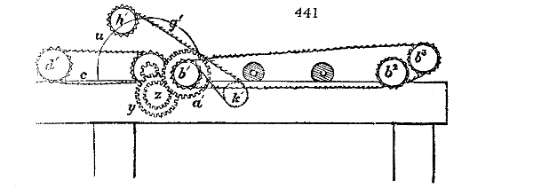
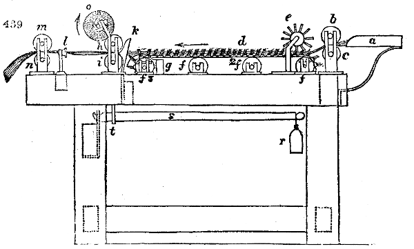
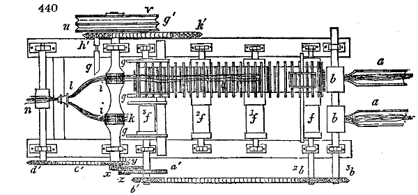
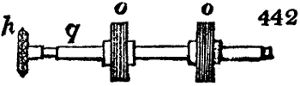
First operation; the conversion of flax into ribands or slivers.—This is effected by subjecting the flax to a series of advancing gills or heckle-teeth, and at the same time drawing out its fibres by means of rollers. Figs. 439, 440, 441, show the outline of the construction of a machine for this purpose. Here two rows of heckles are placed alongside of each other, though only one of them be shown in the ground plan, fig. 440., in order to allow the parts beneath the other to be seen. The flax is placed in the sheet iron channels a a, by laying down one handful after another, so that the points of the second strick reach to only the middle of the first, and thus preserve a uniformity of thickness in the feeding. This process is necessary, since, as every one knows, the heckled stricks are always thick in the middle, and thin at the ends. The flax being introduced between the rollers b and c, is drawn out by their agency, and at the same time subdivided by the heckles d, between whose teeth the pins of the roller e press it down. At the rollers f3 it is loosened from the heckles by the transverse bars which rise from the springs g, after which it is seized by the rollers h i, and drawn again. A little beyond these rollers, it runs through a funnel l, in order to gather the fibres together; in front of these rollers the slivers from both rows of heckles are united, and proceed in one riband through that polished brass funnel; the rollers m n extend this riband, pressing it gently together, and then let it fall into a tin can. The union of the two slivers contributes to the uniformity, since the irregular thicknesses are thereby compensated. The diameter of the roller c, is equal to that of each of the cylinders f, f1, f2, f3; and the whole five move with equal velocity. The same correspondence exists between the rollers n and i. Thus the sliver of flax is not stretched either by its passage from e, upon the heckles, nor between i and n, but solely in passing from the heckles to the rollers i h. The heckle teeth of this machine do not stand perpendicularly, but are bent somewhat backwards; so as to retain the flax more firmly. The revolving cylindrical brush o, is placed over and a little in front of the pressing roller h, in order to take off all the filaments of flax adhering to their circumference, and to toss them onwards where they may again unite with the slivers. For the sake of perspicuity, the rollers h, and those brushes are left out in fig. 440., but the latter are particularly shown in fig. 442., while a portion of their axis q, is however shown in fig. 440. The pressure of the cylinder h, upon the cylinder i, is produced by the weight r, fig. 439., which hangs upon the lever s; the lever pulls down at t, a vertical rod, whose upper hook-shaped end embraces the axis of h in the middle of its length.
Second principal operation; the formation of rovings.—Mr. Wordsworth’s improvements in machinery for preparing, drawing, and roving flax, hemp, wool, and other fibrous substances, consists in a novel contrivance or mechanism to be adapted to the machine commonly called the gill, employed for preparing, drawing, and roving flax and hemp, and for combing and spinning long wool; which improvements allow the points of the travelling heckles to continue longer in operation than in the ordinary construction of gill, and cause the heckle points to be withdrawn from the fibres at the end of the stroke without the possibility of their drawing the fibres down with them.
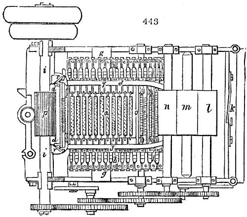
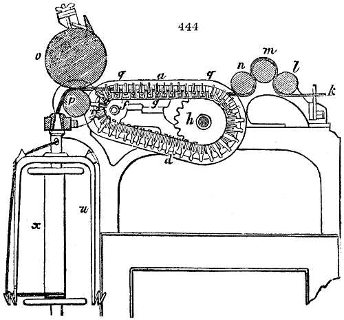
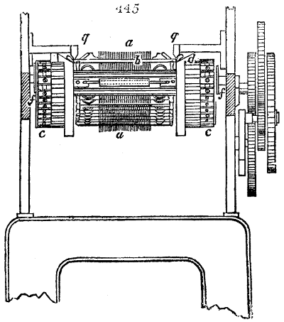
The manner of effecting this object will be seen by reference to the several figures which exhibit a gill on this improved plan in different views. Fig. 443. is a plan or horizontal view, exhibiting the upper surface of the machine; and fig. 444. is a longitudinal section taken through the middle of the machine: fig. 445. is a representation of the front of the machine, but in which several parts have been removed to show the action of the heckles more perfectly.
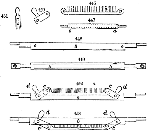
The several heckles a a a are formed by a series of needles or heckle points set into a metal bar, as represented on an enlarged scale in figs. 446. and 447. These bars are each of them suspended in a frame or carriage b b b (shown in two views at figs. 448. and 449.), by means of double jointed levers c c, seen in two positions, at figs. 450. and 451.; the heckle bar, its levers and carriage or frame, being shown put together in figs. 452. and 453.
When the heckles are in operation, the points are raised, as in fig. 452.; but when they are withdrawn from the fibres, then the points are sunk down into the carrying frames, as fig. 453.
These two positions of the heckles are produced by the knobs or parts d, that project from the jointed levers c, acting against the edges of guide bars, which will be explained in describing the operations of the machine.
The several heckles are adapted and made to work in the machine by attaching the ends of the respective frames or carriages b, to travelling endless chains e e, seen in figs. 443., 444., and 445. These endless chains pass over fluted guide rollers f f, seen best in figs. 444. and 445., and over horizontal bars g g, seen best in figs. 443. and 444. The chains with the heckles are driven through the machine by rotatory spur wheels h h; see figs. 443. and 444., the teeth of which take into the spaces between the cylindrical parts of the several heckle carriages b b, and consequently drive the heckles forward; and these spur wheels are actuated by a train of toothed geer from the first driving shaft i, which gives motion to all the operative parts of the machine.
If flax, hemp, long wool, or other fibrous material, be passed into the machine at the back part by a feeding cloth or creeper through a guide k, best seen in figs. 443. and 444., and be conducted under and over the feeding rollers l, m, and n, and over the heckles a a a to the drawing rollers o and p, and thence to the flyer and bobbin, or to a receiving can, the fibres will be opened in their progress, and combed by the points of the heckles entering into and separating the fibres, the material being drawn by a different speed to that with which the heckles travel.
This operation of preparing, drawing, and roving flax and hemp, and the general construction of a machine of this kind being well understood, it is not necessary to explain its details, excepting as respects those parts which constitute the present improvements.
It will be perceived, by reference to figs. 443. and 444., that the knobs d, which project from the jointed levers c, as they travel along the machine, bear against the outer edges of the two fixed guide bars q q that extend along the top of the machine above the heckles, which keep the heckle points raised, as in fig. 451. This will also be very evidently seen in the front view of the machine, fig. 445., where the upper heckle bar a is raised in its carriage b, by the knobs d d bearing against the outer edges of these guide bars q q. But when the endless chains e e, which support and conduct the frames or carriages of the heckles, have advanced the heckle points to within a very little distance of the drawing rollers (see fig. 444.) then the knob d of the jointed levers at each end of the heckle bar passes the ends of the guide bars q q, and they immediately come in contact with two inclined planes r r, seen in figs. 443. and 444., which instantly depress the levers c, and consequently cause the heckle bar a, with its points to descend in the frame or carriage b, withdrawing the points from the fibres of the material almost in a perpendicular direction.
The heckles that have become thus depressed pass with their carriages by the traversing of the endless chains along the under part of the machine, and when they arrive at the back, and begin to rise, the guide bars q q, being at their commencement slightly bent, conduct the knobs b of the levers c until they are forced back into the positions first described, whereby the heckle points are raised, as they come to the upper part of the machine, into effective operation. The fibres of material operated upon, after passing through the drawing process between the rollers, may be roved, twisted, or spun, by the employment of a bobbin and flyer, as shown in fig. 444., or may be delivered into a can, to be roved, twisted, or spun, by other machinery, by substituting a pair of conducting rollers instead of the bobbin and flyer, which shall conduct the sliver of material into a tin can below.
The descent of the heckles a, into their frames b, by the falling of the levers c, c, precludes the possibility of the fibres of the material operated upon being carried down under the machine by the points, as frequently happens in gill machines of the ordinary construction; and this mode of mounting the heckles and traversing them with the assistance of the guide bars q, q, and inclined planes r, r, allows the heckle points to be brought much nearer to the drawing rollers o, p, by means of the metal bars in which the heckle points or needles are set, falling below the centre of the endless chain e, e, as shown in figs. 443. and 444., and thereby affords the means of preparing, drawing, and roving various qualities of flax, hemp, wool and other fibrous materials, particularly such as have a much shorter staple than any fibrous materials hitherto operated upon in gill machinery.
Another most ingenious and effective improvement made of late years in the flax spinning machinery, is that patented by Messrs. Westley and Lawson, in August 1833, and since then introduced into practice with great advantage. It applies to the gill or mechanism employed for opening, straightening, and separating the fibres of flax, hemp, and long wool in the operation of slivering. The peculiar feature here is a method of driving the heckle bars through the gill machine by means of perpetual screws or worm shafts, instead of by chains and spur wheels, as in the former constructions.
The heckle bars which lie across the machine, are, by the present patentees, supported at their ends by fixed horizontal guide rails, on which they slide, while the extremities of the heckle bars are inserted in the helical grooves of the worm shafts, which are placed in horizontal positions at the sides of the machine; and hence the rotatory motions given to these screw shafts, cause the heckle bars to be driven along the guide rails with an uniform simultaneous movement.
The heckle bars having performed their usual office, that is, having combed and separated the fibres of the material as they move onward, are at the front part of the machine depressed and put out of operation by means of rotatory cams; and by the assistance of guide levers, each heckle bar, when it arrives at the end of the upper horizontal guide rail, is conducted down to the lower horizontal guide rails, where the extremities of the comb-bars falling into the helical grooves of a lower pair of worm shafts, revolving in an opposite direction to the former, thereby give the heckle bars a retrograde movement. When they arrive at the back end of their horizontal guide rails, they are, by similar rotatory cams, raised again to the upper horizontal guide rails, which coming into geer with the upper worm shafts, are moved onwards as at first.
By this means a succession of heckles is continually advancing upon the upper guide rails, having their points in constant operation between the fibres of the textile materials, while their vertical position is secured during their whole course.
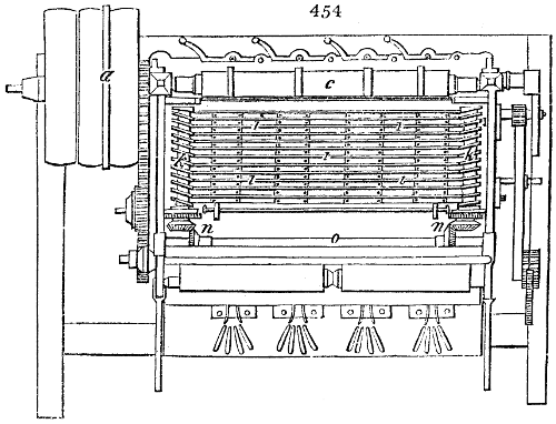
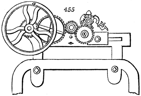
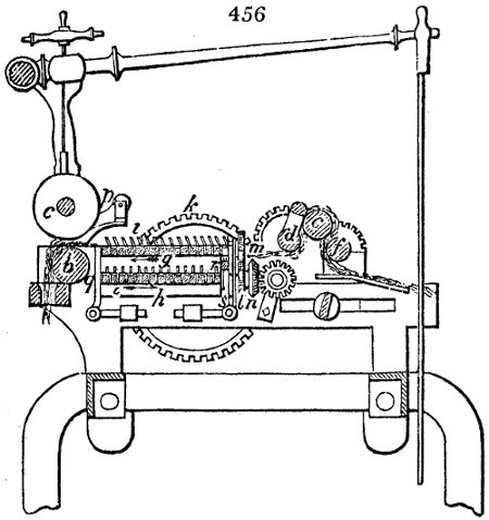
Fig. 454. is a horizontal representation of a gill machine, shewing the present improvements; but some of the upper portions of the machine are removed, to let the working parts be seen more clearly. Fig. 455. is a side view of the gill; and fig. 456. a vertical section taken longitudinally. The driving rigger or pulley a, is fixed upon the front roller b, commonly called the drawing roller, because when pressed upon by the upper wooden roller c, it draws out the fibres between them. The rollers d, e, f, are the ordinary back or holding rollers, for retaining the fibres, while they suffer powerful traction by the rollers b, c, over the needles or points of the heckle bars. The upper guide rail above mentioned, upon which the heckle bars slide, is shown at g, in fig. 456., and the lower guide rail at h; the series of heckle bars with their needles are represented at i, i, i, i, i, i; the upper worm shafts k, k, are mounted in brackets made fast to the sides of the frame; a similar pair of worm shafts l, being mounted in like manner below. These worm shafts k and l, on each side are connected together by toothed wheels m, and upon the axles of the lower worm shafts, bevelled pinions n are fixed, which take into corresponding bevel pinions on the transverse shaft or axle o. This shaft o, being connected by a train of toothed wheel work with the axle of the drawing roller b, as shown in figs. 454. and 455., the rotation of the roller b, causes the shaft o to turn also, and the bevel geer n and o, produce the rotatory motion of the worm shafts k and l, which turn in contrary directions.
It will be seen, from fig. 454., that the ends of the heckle bars i, have nibs or projections which fall into the grooves of the screw or worm shaft, and that being supported below, upon their guide rails, as the worm-shafts k k revolve, the upper range of heckle bars will be progressively advanced towards the front part of the machine. By referring to fig. 456. it will be perceived, that as each heckle bar arrives at the front end of the guide rail g, a finger p, called a tappet or cam, on the shaft k, strikes it down to the lower guide rails h; and, in order that its descent may be truly vertical, weighted levers q q, in front, are made to press against the face of the heckle bar as it descends. This bar having now arrived at the lower guide rails h, lets fall its nibs into the grooves of the lower worm shafts l, by whose rotation the heckle bar is made to retrograde, or return towards the back of the machine. When the heckle bar has reached the hinder end of the guide rail h, a finger or tappet, r, on the lower worm shaft, comes under it and raises the heckle bar, guided by the back-weighted levers s, as shown in fig. 456., till it is elevated to the level of the upper guide rail g; when the threads of the upper worm-shafts take hold of its nibs as before, and conduct it forward upon the guide rail in the way already described. Thus the continued rotation of the worm shafts k k, and l l, causes the whole series of heckle bars to travel along the guide rails, and the tappets p and r, by alternately depressing and raising them at the ends of the said rails, cause them to move in a regular circuit, yet so as to preserve their verticality.
The claim made under this patent is, for every mode in which screw or worm shafts may be adapted to conduct the bars carrying the needles or heckle-teeth through a machine for preparing, drawing, or roving textile fibres.
In December 1835, Messrs. Hope and Dewhurst obtained a patent for improvements in the manufacture of flax, which deserve notice. These are of both a chemical and mechanical nature. The first consists in steeping the flax in dilute sulphuric acid, of a certain strength, and for a certain time, proportioned to the quality of the fibres, the coarser requiring the stronger application. By this means the gummy matter and the outer shell will be loosened and easily detached. It is then to be passed between squeezing rollers, afterwards well washed, boiled in a solution of soap and water for a few hours, and finally passed again through the rollers. These processes may be repeated till the flax acquires the desired glossiness and separation of fibres. It is next to be beaten, and passed once or twice over an ordinary heckle or stiff brush.
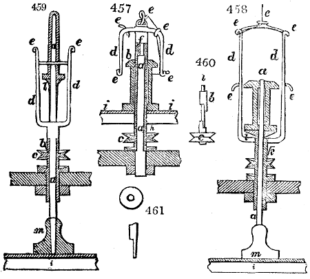
The second part, or the mechanical, is represented by the figures 457., 458., 459., 460., and 461. Fig. 457. is a sectional elevation in part of the construction of the spindle, bobbin and flyer proposed for spinning all kinds of flax or hemp. Fig. 458. answers for spinning coarser yarns; fig. 459. shows how yarns are to be spun for weft, and wound upon what is called a “pin cop bobbin.”
a a a is the stationary or fixed spindle of the ordinary throstle frame, which is surrounded by the tube b b, and connected to the wharve or pulley c, by which the flyer d is driven. The flyer is furnished with guides or conductors e e, which lead the yarn immediately to the bobbin; this flyer is also provided with a small central shaft which supports it, and runs in the small cup or recess at the top of the stationary spindle a, and is fixed with the flyer to the tube b b, which is altogether carried round or driven by the wharve c.
It will be seen by fig. 460., that the wharve c, and tube b, are connected at bottom by a half-lap coupling joint or clutch; this is for the purpose of allowing the tube b to be slidden up the spindle, and more readily removing the bobbin when it is full of yarn, without stopping the frame, or removing the band from the wharve c, the tube of which runs in the step or cup h, fixed upon the bolster rail near the bottom of the throstle frame. The traversing of the bobbin or the copping motion is effected exactly in the same manner as in ordinary throstles, that is, by the lifting and lowering of the copping rail i, which in this instance supports the bobbin. In fig. 458. the flyer is constructed of twice the length of the bobbin, to allow this to rise and fall freely within it, and is connected at top by a slight cross piece, for the purpose of preventing the arms of the flyer from expanding by the centrifugal force, when turning with great velocity. The flyer for spinning coarse numbers requires to have an inner tube k, to support the spindle. The bobbins are supported upon a washer l, l. The spindle is allowed to revolve in a slight degree by the friction of the drag-weight m, m. This weight has a hole formed in it with a flat side, as shown in fig. 461.
Flax has been for a long period spun wet in the mills; a method no doubt copied from the practice of housewives moistening their yarn with their saliva at the domestic wheel. Within a few years the important improvement has been introduced, of substituting hot for cold water, in the troughs through which the fibres in the act of spinning pass. By this means a much finer, smoother, and more uniform thread can be spun than in the old way. The flax formerly spun to twelve pounds a bundle, is, with hot water, spun to six. The inconvenience of the spray thrown from the yarn on the flyers remains; aggravated by increased heat and dampness of the room, where this hot process goes on. Being a new expedient, it receives daily changes and ameliorations. When first employed, the troughs of hot water were quite open; they are now usually covered in, so as almost entirely to obviate the objections to which they were previously liable. With the covers has been also introduced a new method of piecening or joining on any end, which may have been run down, namely, by splicing it to the adjoining roving, whereby it is carried through the water without imposing a necessity on the spinner to put her hand into the water at all. In some places she uses a wire, for the purpose of drawing through the end of the roving to mend a broken yarn.
This may be considered the inherent evil of flax-spinning,—the spray thrown off by the wet yarn, as it whirls about with the flyer of the spindles. A working dress, indeed, is generally worn by the spinners; but, unless it be made of stuff impermeable to water, like Macintosh’s cloth, it will soon become uncomfortable, and cause injury to health by keeping the body continually in a hot bath. In some mills, water-proof cloth and leather aprons have actually been introduced, which are the only practicable remedy; for the free space which must be left round the spindles for the spinner to see them play, is incompatible with any kind of fixed guard or parapluie.
There was before the late Factory Bill passed, a class of very young children employed in the flax mills, under the name of little doffers, forming generally a troop of from four to ten in each spinning-room, who, the moment they perceived the bobbins of any frame or side of a frame exhausted of roving, ran together, and furnished it with full ones as quickly as possible. They were not numerous in all, but they had an occupation requiring a great activity and attention. It was practised also in the fine spinning-rooms, which are perfectly free from dust; and, as it involved a kneeling and stooping position, seemed peculiarly appropriate to children, and is still done by them at a somewhat more advanced age.
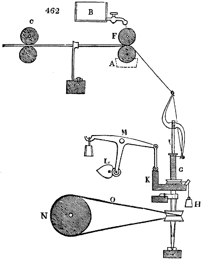
The adjoining fig. 462. will serve to explain the mechanism by which the fine spinning of flax is performed. The front pair of drawing rollers represented at F, was at one time moistened by letting water trickle upon it, from a vessel B, furnished with a stopcock placed a little above, or by immersing one half of the under-roller in the water-trough as at A. The roller pair C, which receives the fine rovings from bobbins placed on skewers or upright pins in the creel behind, is so mounted as to be fixed at any desired distance from the front rollers F. This distance should be always a little more than the average length of the filaments of the line; for if it were equal to it, they would be seized at both ends by the two pairs of rollers, which move with different velocities, and would be torn asunder, instead of being drawn out alongside of each other. The front rollers indeed move in many such machines four times faster than the back pair. The rest of this flax-spinning apparatus resembles in every respect the throstle frame of the cotton-spinner. The thread, as it escapes from the front rollers, gets twisted by the spindle and flyer, and wound up in constant progression on the bobbin, the motion of the latter being retarded either by a washer of leather beneath its lower end, or sometimes, as shown in the figure, by a weighted lever H, suspended from a cord, which embraces the pulley-groove turned on the lower end of the bobbin. This friction of this cord on the pulley, which may be varied by changing the length of leverage at which the weight acts, gives the bobbin the requisite retardation for winding up the yarn.
The bobbin G, at the same time that it has this retarded movement of revolution on its axis, has another motion up and down on the spindle I, to present itself at different points to the thread, and to cause the equal distribution of this over the surface of the bobbin-barrel. This latter motion is given by a double eccentric L, which by turning slowly on its axis, makes the balance-lever M oscillate, and thereby raises or depresses the bobbin-rail with its row of spindles. N is a section of the long tin drum, which extends the whole breadth of the frame, and communicates its rotatory motion, derived from the steam-pulley, to the spindles, by the intervention of the endless cotton cords O, as also to the fluted rollers C, F, and to the axis of the heart-shaped or eccentric wheel L, working in an endless screw.
The ratio of the velocity of the rollers of supply C, with the front or delivering rollers F, and with the spindles, is proportional to the fineness of the yarn. For low numbers, the draught is usually fourfold. The speed of the spindles also varies with the quality of the yarn, according as it is intended for warp or weft; the former requiring more twist than the latter; but never so much as to cause it to snarl into a knot, when left free to turn on itself.
One of the most important improvements hitherto made in the spinning of flax is that for which James Kay, of Preston, obtained a patent in July, 1825. Its peculiar feature is the maceration in warm water of the slivers or rovings, previously to spinning them, by conducting them into tin cans, with open bottoms, fitted into circular boxes having holes like a cullender, and immersed into a trough of warm water. The slivers as they pass from the rollers are let fall through the cans into these boxes, when they are to be repeatedly pressed and beaten down by a plunger, or the action of rollers, as may be most convenient. The material must be thoroughly freed from air, and macerated. After five or six hours it is to be removed from the water, and placed in its compressed state at the back part of a drawing and spinning machine. The cake being now turned over, the end of the roving first deposited in the can is drawn out with care, then raised up, and passed over a tension roller to the drawing apparatus. The first pair of rollers for the drawing process merely retains the filaments; while at a distance of two inches and a half the drawing rollers are placed. Both are fluted for the purpose of taking firm hold of the material; and the drawing pair is made to move eight times quicker than the retaining. As the flax fibres have in this state little or no elasticity, and as they adhere loosely in their macerated condition, the drawing rollers must be placed thus close to the retaining rollers, and being made to move at a proper speed, produce an extremely attenuated thread.
The adjoining table represents, in three compartments, the most important rooms in a flax-mill, viz.:—
I. The tow preparing room.
II. The line preparing room for the long flax.
III. One room of spinning machines as a pattern for the rest.
TOW PREPARING ROOM.
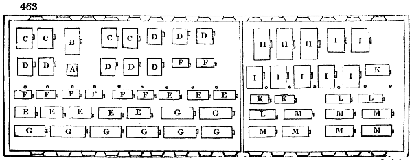
A, lap machine; B, 4-feet breaker card; C, 3 feet 6 inches ditto; D, 3-feet finisher card, 3 workers; E, cut tow, second drawing, 5 heads; F, cut tow, first drawing, 4 heads; G, cut tow, reg. roving, 32 spindles; H, 4-feet breaker card; I, 4-feet finisher ditto; K, long tow, first drawing, 3 heads; L, long tow, second drawing, 4 heads; M, long tow, roving 4 spindles.
LINE PREPARING ROOM.
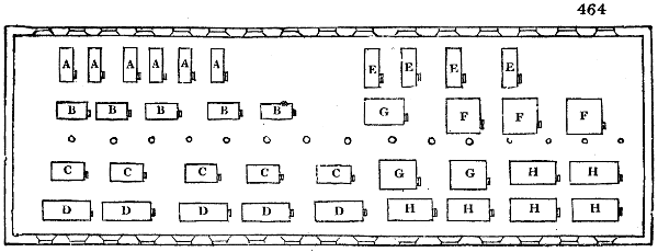
A, cut line, first drawing; B, cut line, second drawing, 4 heads; C, cut line, third drawing, 5 heads; D, cut line, reg. roving 32 spindles each; E, long line, first drawing; F, long line, second drawing, 3 heads each; G, long line, third drawing, 4 heads each; H, long line, roving 16 spindles.
SPINNING ROOM.
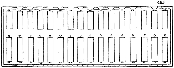
I. The line preparing room comprehends:—
1. Heckling machines with heckles.
2. Line spreaders, or first drawing slivers.
3. Frames for the second drawing, of 3 heads each.
4. Frames for the third drawing, of 4 heads each.
5. Roving frames of 16 spindles each.
6. Spare fallers for first drawing with gills.
7. Ditto ditto for second and third drawing with ditto.
8. Ditto ditto for roving.
II. The cut flax line preparing room:—
1. Sets of heckling frames (excentric.)
2. Cutting or breaking machine.
3. Line spreaders or drawing ditto.
4. Frames for second drawing, 4 heads each.
5. Ditto es for third ditto,awing,5 ditto.
6. Ditto, regulator roving, 32 spindles each.
7. Spare fallers with gills for first drawing.
8. Ditto, dittors with gills for second and third ditto.
9. Ditto, ditto, with gills for roving.
III. Long or uncut flax tow preparation:—
1. Lap machine.
2. Breaker cards, 4 feet diameter.
3. Finisher ditto, ditto.
4. Frames for first drawing, 3 heads each.
5. Ditto for second drawing, 3 heads each.
6. Ditto for roving, 16 spindles each.
7. Spare fallers, with gills for first and second drawing.
8. Ditto, ditto, ditto,h gillsfor roving.
IV. Cut flax tow preparation:—
1. Lap machine.
2. First breaker cards, 4 feet diameter.
3. Second ditto, ditto, 3 feet 6 inches ditto.
4. Finisher cards with 8 workers.
5. First drawing frames, of 4 heads each.
6. Second ditto, ditto, of 5 ditto.
7. Frames for regulator roving, 32 spindles each frame.
8. Spare fallers with gills for first and second drawing.
9. Ditto, ditto,s with gills for roving.
V. Spinning rooms for both lines and tows:—spindles in frames in a number proportional to the number of the above preparation machines; and consequently to the quantity and quality of the flax yarn intended to be spun.
VI. Utensils and tools; such as cards clothing with needle pointed filleting.
Observations upon the above statement of the series of machinery requisite in a modern flax mill of the most improved construction:—
The long or uncut flax to be spun into yarns averaging 30 leas per lb.
Each heckling machine will produce about 41⁄2 cwts. per day, which would be distributed into 200 lbs. of line, and 2662⁄3 of tow.
The total with 3 machines would be therefore 600 lbs. of line, and 800 lbs. of tow.
The preceding statement contains three systems of line preparing, each system being composed of—
1 line spreader, or first drawing;
1st frame of 3 heads; 2d ditto, 2 slivers each;
1 ditto of of 4 ditto;s;3d ditto, ditto ditto;
2 ditto rovings of 32 spindles, which are capable of supplying about 640 spinning ditto;
1 line spreader being allowed for contingencies.
The above statement contains 3 systems of tow (uncut) preparation, each system being composed of—
1 breaker card;
2 finisher ditto,
1 frame of first drawing, 3 heads of 4 slivers each;
1 dittoe of second ditto, 4 ditto,s of 4 ditto ditto;
21⁄3 ditto rovings or 37 spindles, which are capable of supplying about 660 spinning ditto;
1 lap machine being sufficient for 2 or 3 systems;
1 extra finisher is deemed desirable.
The statement contains 2 systems of heckling machines for cut flax, a system consisting of either 8 or 10 machines; for the coarser work, 8 machines in succession finer and finer, are sufficient; but for the finest 10 or 12 are required. Each system will produce between 2 and 300 lbs. per diem, of raw flax, heckled, divided on the average into 170 lbs. line, 280 lbs. tow, which will about equal the supply of the 5th system contained in the statement, each consisting of—
1 line spreader or 1st drawing;
1 frame 2d drawing; 4 heads 4 slivers each;
1 dittoe 3d ditto,ing; 5 dittods4 ditto ditto;
1 ditto roving 32 spindles; and are capable of supplying about 480 ditto, of spinning.
The statement contains 2 systems of tow (cut flax) preparings, each system being composed of—
2 second breaker card;
4 finishers ditto;
4 frames 1st drawing, 4 heads each 4 slivers;
4 dittoes 2d ditto,ing, 5 ditto ditto,h 4 ditto;
4 regulator rovings 128 spindles, and are capable to supply about 1800 spinning ditto.
1 first-breaker card and lap frame are sufficient to 2 or 3 systems.
Summary view:—
Long or uncut line 3 systems of 640 spindles = 1920
Ditto — tow 3 ditto 660 ditto 1980 3900
Cut — line 5 ditto 480 ditto 2400
Ditto — tow 2 ditto 1800 ditto 3600 6000
Total of spinning spindles 9900
3900 spindles, at an average of 30 leas yarn per lb., would turn off 9 leas per spindle per diem with waste circa 1400 lbs.
6000 spindles, at an average of 100 leas yarn per lb., would turn off 6 leas per spindle per diem with waste circa 450 lbs.
Yarns produced: £. s. d.
Of average 30 leas per lb. per week circa 1050 boles at 9s. 472 10 0
Of ditto 100 ditto — — 1080 — 486 0 0
Total weekly produce 2130 958 10 0
£. s. d.
Weekly charges, wages, &c. 150 0 0
Flax 400 0 0
Weekly expenses 40 0 0
Interest on 60,000l. 10 per annum 120 0 0 710 0 0
Weekly profit 248 10 0
Measures of flax yarn; and statistics of the linen trade for the United Kingdom.
One lea of flax yarn at Leeds is = 300 yards.
One spindle Scotch = 38 leas = 11400 yards.
One rand = 6 ditto = 1800 ditto.
One dozen is 12 rands = 72 ditto = 21600 ditto.
When yarn is estimated in Nos. it implies the number of leas in one pound weight; as in cotton, it means the number of hanks of 840 yards each in one pound.
Imports of flax and tow, or codilla of hemp and flax, at a duty of 1d. per cwt., in
1834. 1835. 1837. 1838.
lbs. lbs. lbs. lbs.
811,722 740,814 1,529,116 1,002,256
Retained for consumption.
794,272 728,143 1,532,059 1,002,408
Linen yarn exported 2,611,215
Linen manufactures exported, in- cluding flax yarn, declared value £3,208,139 £3,645,097 £2,613,293
FLINT. (Pierre à fusil, Fr; Feuerstein, Germ.) The fracture of this fossil is perfectly conchoidal, sometimes glossy, and sometimes dull on the surface. It is very hard, but breaks easily, and affords very sharp-edged splintery fragments; whence it is a stone which strikes most copious sparks with steel. It is feebly translucid, has so fine and homogeneous a texture as to bear polishing, but possesses little lustre. Its colours are very various, but never vivid. The blackish-brown flint is that usually found in the white chalk. It is nearly black and opaque, loses its colour in the fire, and becomes grayish-white, and perfectly opaque. Flints occur almost always in nodules or tubercular concretions of various and very irregular forms. These nodules, distributed in strata among the chalk, alongside of one another and almost in contact, form extensive beds; interrupted, indeed, by a multitude of void spaces, so as to present, if freed from the earthy matter in which they are imbedded, a species of network with meshes, very irregular both in form and dimension.
The nodules of silex, especially those found in the chalk, are not always homogeneous and solid. Sometimes there is remarked an organic form towards their centre, as a madrepore or a shell, which seems to have served as their nucleus; occasionally the centre is hollow, and its sides are studded over with crystals of quartz, carbonate of iron, pyrites, concretionary silex or calcedony, filled with pulverulent silica nearly pure, or silex mixed with sulphur; a very singular circumstance.
Flints are observed to be generally humid when broken immediately after being dug out of the ground; a property which disappears after a short exposure to the air. When dried they become more brittle and more splintery, and sometimes their surfaces get covered at old fractures with a thin film or crust of opaque silex.
Flints calcined and ground to a powder enter into the composition of all sorts of fine pottery ware.
The next important application of this siliceous substance is in the formation of gun-flints, for which purpose it must be cut in a peculiar manner. The following characters distinguish good flint nodules from such as are less fit for being manufactured. The best are somewhat convex, approaching to globular; those which are very irregular, knobbed, branched and tuberose, are generally full of imperfections. Good nodules seldom weigh more than 20 pounds; when less than 2, they are not worth the working. They should have a greasy lustre, and be particularly smooth and fine grained. The colour may vary from honey-yellow to blackish-brown, but it should be uniform throughout the lump, and the translucency should be so great as to render letters legible through a slice about one-fiftieth of an inch thick, laid down upon the paper. The fracture should be perfectly smooth, uniform, and slightly conchoidal; the last property being essential to the cutting out of perfect gun-flints.
Four tools are employed by the gun-flint makers.
First, a hammer or mace of iron with a square head, from 1 to 2 pounds weight, with a handle 7 or 8 inches long. This tool is not made of steel, because so hard a metal would render the strokes too harsh, or dry as the workmen say, and would shatter the nodules irregularly, instead of cutting them with a clean conchoidal fracture.
Second, a hammer with 2 points, made of good steel well hardened, and weighing from 10 to 16 ounces, with a handle 7 inches long passing through it in such a way that the points of the hammer are nearer the hand of the workman than the centre of gravity of the mass.
Third, the disc hammer or roller, a small solid wheel, or flat segment of a cylinder, parallel to its base, only two inches and a third in diameter, and not more than 12 ounces in weight. It is formed of steel not hardened, and is fixed upon a handle 6 inches long, which passes through a square hole in its centre.
Fourth, a chisel tapering and bevelled at both extremities, 7 or 8 inches long, and 2 inches broad, made of steel not hardened; this is set on a block of wood, which serves also for a bench to the workmen. To these 4 tools a file must be added, for the purpose of restoring the edge of the chisel from time to time.
After selecting a good mass of flint, the workman executes the following four operations on it.
1. He breaks the block. Being seated upon the ground, he places the nodule of flint on his left thigh, and applies slight strokes with the square hammer to divide it into smaller pieces of about a pound and a half each, with broad surfaces and almost even fractures. The blows should be moderate, lest the lump crack and split in the wrong direction.
2. He cleaves or chips the flint. The principal point is to split the flint well, or to chip off scales of the length, thickness, and shape adapted for the subsequent formation of gun flints. Here the greatest dexterity and steadiness of manipulation are necessary; but the fracture of the flint is not restricted to any particular direction, for it may be chipped in all parts with equal facility.
The workman holds the lump of flint in his left hand, and strikes with the pointed hammer upon the edges of the great planes produced by the first breaking, whereby the white coating of the flint is removed in small scales, and the interior body of the flint is laid bare; after which he continues to detach similar scaly portions from the clean mass.
These scaly portions are nearly an inch and a half broad, two inches and a half long, and about one-sixth of an inch thick in the middle. They are slightly convex below, and consequently leave in the part of the lump from which they were separated a space slightly concave, longitudinally bordered by two somewhat projecting straight lines or ridges. The ridges produced by the separation of the first scales must naturally constitute nearly the middle of the subsequent pieces; and such scales alone as have their ridges thus placed in the middle are fit to be made into gun-flints. In this manner the workman continues to split or chip the mass of flint in various directions, until the defects usually found in the interior render it impossible to make the requisite fractures, or until the piece is too-much reduced to sustain the smart blows by which the flint is divided.
3. He fashions the gun-flints. Five different parts may be distinguished in a gun-flint. 1. The sloping facet or bevel part, which is impelled against the hammer of the lock. Its thickness should be from two to three twelfths of an inch; for if it were thicker it would be too liable to break; and if more obtuse, the scintillations would be less vivid. 2. The sides, or lateral edges, which are always somewhat irregular. 3. The back or thick part opposite the tapering edge. 4. The under surface, which is smooth and rather concave. And 5. The upper face, which has a small square plane between the tapering edge and the back, for entering into the upper claw of the cock.
In order to fashion the flint, those scales are selected which have at least one of the above mentioned longitudinal ridges; the workman fixes on one of the two tapering borders to form the striking edge, after which the two sides of the stone that are to form the lateral edges, as well as the part that is to form the back, are successively placed on the edge of the chisel in such a manner that the convex surface of the flint, which rests on the forefinger of the left hand, is turned towards that tool. Then with the disc hammer he applies some slight strokes to the flint just opposite the edge of the chisel underneath, and thereby breaks it exactly along the edge of the chisel.
4. The finishing operation is the trimming, or the process of giving the flint a smooth and equal edge; this is done by turning up the stone and placing the edge of its tapering end upon the chisel, in which position it is completed by 5 or 6 slight strokes of the disc hammer. The whole operation of making a gun-flint, which I have used so many words to describe, is performed in less than one minute. A good workman is able to manufacture 1000 good chips or scales in a day (if the flint-balls be of good quality), or 500 gun-flints. Hence, in the space of 3 days, he can easily cleave and finish 1000 gun-flints without any assistance.
A great quantity of refuse matter is left, for scarcely more than half the scales are good, and nearly half the mass in the best flints is incapable of being chipped out; so that it seldom happens that the largest nodules furnish more than 50 gun-flints.
Flints form excellent building materials; because they give a firm hold to the mortar by their irregularly rough surfaces, and resist, by their nature, every vicissitude of weather. The counties of Kent, Essex, Suffolk, and Norfolk contain many substantial specimens of flint-masonry.
FLOSS, of the puddling furnace, is the fluid glass floating upon the iron produced by the vitrification of the oxides and earths which are present.
FLOSS-SILK (Filoselle, Bourre de soie, or fleuret, Fr.); is the name given to the portions of ravelled silk broken off in the filature of the cocoons, which is carded like cotton or wool, and spun into a soft coarse yarn or thread, for making bands, shawls, socks, and other common silk fabrics. The floss or fleuret, as first obtained, must be steeped in water, and then subjected to pressure, in order to extract the gummy matter, which renders it too harsh and short for the spinning wheel. After being dried it is made still more pliant by working a little oil into it with the hands. It is now ready to be submitted to the carding engine. See Cotton Manufacture. It is spun upon the flax wheel.
The female peasants of Lombardy generally wear clothes of homespun floss silk. Of late years, by improved processes, pretty fine fabrics of this material have been produced both in England and France. M. Ajac, of Lyons, presented at one of the French national exhibitions of the objects of industry, a great variety of scarfs and square shawls, of bourre de sole, closely resembling those of cachemere.
FLOUR; the finely ground meal of wheat, and of any other corns or cerealia. See Bread.
FLOUR OF WHEAT, Adulterations of, to detect.
The first method is by specific gravity. If potato flour be added, which is frequently done in France, since a vessel which contains one pound of wheat flour will contain one pound and a half of the fecula, the proportion of this adulteration may be easily estimated. If gypsum or ground bones be mixed with the flour, they will not only increase its density still more; but they will remain after burning away the meal.
The second method is by ascertaining the quantity of gluten which the suspected sample will afford, by the process prescribed under the article Bread. The two following chemical criteria may also be employed.
1st. Nitric acid has the property of colouring wheat flour of a fine orange yellow, whereas it affects the colour neither of fecula nor starch.
2nd. Pure muriatic acid colours good wheat flour of a deep violet, but dissolves fecula or starch, and forms with it a light, colourless, viscous fluid, decomposable by alkalis. It may also be observed, that as fecula absorbs less water than flour, this affords a ready means of detection.
The adulteration with bean or pea flour may be detected by pouring boiling water upon it, which developes the peculiar smell of these two substances.
FLOWERS (Fleurs, Fr.; Blumen, Germ.) of benzoin, of sulphur, of zinc, &c., is the appellation given by the older chemists to such substances as were obtained in a pulverulent or rather minutely crystalline form by the process of sublimation.
FLOWERS, ARTIFICIAL, MANUFACTURE OF. The art of representing by flowers, leaves, plants, &c., vegetable nature in her ornamental productions, constitutes the business of the artificial florist. The Italians appear to have been the first people in Europe who excelled in the art of making artificial flowers; but of late years the French have been most ingenious in this branch of industry.
Ribbons folded in different forms and of different colours were originally employed for imitating flowers, by being attached to wire stems. This imitation soon gave way to that by feathers, which are more delicate in texture, and more capable of assuming a variety of flower-like figures. But a great difficulty was encountered in dyeing them with due vivacity. The savages of South America manufacture perfect feather flowers, derived from the brilliant plumage of their birds, which closely resemble the products of vegetation. The blossoms and leaves are admirable, while the colours never fade.
The Italians employ frequently the cocoons of the silkworm for this purpose; these take a brilliant dye, preserve their colour, and possess a transparent velvety appearance, suitable for petals. Of late years, the French have adopted the finest cambric for making petals, and the taffeta of Florence for the leaves. M. de Bernardière employs whalebone in very thin leaves for artificial flowers; and by bleaching and dyeing them of various hues, he has succeeded in making his imitations of nature to be very remarkable.
The colouring matters used in flower dyeing are the following:—
For red; carmine dissolved in a solution of salt of tartar.
For blue; indigo dissolved in sulphuric acid, diluted and neutralized in part by Spanish whitening.
For bright yellow; a solution of turmeric in spirit of wine. Cream of tartar brightens all these colours.
For violet; archil, and a blue bath.
For lilac; archil.
Some petals are made of velvet, and are coloured merely by the application of the finger dipped in the dye.
FLUATES, more properly fluorides (Eng. and Fr.; Flusssäure, Germ.); compounds of fluorine and the metals; as fluor spar, for example, which consists of fluorine and calcium.
FLUOR SPAR. (Chaux fluatée, Fr.; Spath fluor, Germ.) This mineral often exhibits a variety of vivid colours. It crystallizes in the cubic system; with regular octahedral and tetrahedral cleavages; spec. grav. 3·1 to 3·2; scratches calc spar, but is scratched by a steel point; usually phosphorescent with heat; fusible at the blowpipe into an opaque bead; acted on by the acids, with disengagement of a vapour which corrodes glass; its solution affords precipitates with the oxalates, but not with ammonia. Its constituents are, fluorine, 48·13; calcium, 51·87 in 100.
Fluor spar occurs subordinate to metallic veins; as to those of lead, in Derbyshire; of tin, in Saxony and Bohemia; but it is found also in masses or veins, either in crystalline rocks, associated with quartz, heavy spar, &c., as in Auvergne, Forez, Vosges, Norberg in Sweden; Norway; Petersburg; near Hall; Gourock, in Scotland, &c.; or among secondary limestones, slates, and sandstones, in Derbyshire, Cumberland, Cornwall, and New Jersey. It exists also in the amygdaloids of Scotland, and in the volcanic products of Monte Somma at Vesuvius. The variously coloured specimens, called Derbyshire spar, are worked upon the turning lathe into vases and other ornamental objects.
FLUX, (Eng. and Fr.; Fluss, Germ.) signifies any substance capable of promoting the fusion of earths or metallic ores by heat. White flux is the residuum of the deflagration in a red hot crucible, of a mixture of two parts of nitre, and one of cream of tartar. It is in fact merely a carbonate of potash. Black flux is obtained when equal parts of nitre and tartar are deflagrated. It owes its colour to the carbonaceous matter of the tartaric acid, which remains unconsumed; the quantity of nitre being too small for that purpose. The presence of the charcoal renders this preparation a convenient flux for reducing calcined or oxidized ores to the metallic state. Limestone, fluor-spar, borax, and several earthy or metallic oxides are employed as fluxes in metallurgy.
FLY POWDER; the black coloured powder obtained by the spontaneous oxidizement of metallic arsenic in the air.
FODDER; is the name of a weight by which lead and some other metals are sold in this country. It varies in its amount in different parts of the kingdom; being in Northumberland estimated at 21 cwts., and in other counties 22, 23 or even more cwts.
FONDUS; is the name given by the French to a particular style of calico printing resembling the rainbow, in which the colours are graduated or melted (fondus) into one another, as in the prismatic spectrum. See Paper hangings, for a description of the process.
FORGE; (Eng. and Fr.; Feuer, Germ.) is the name either of the furnace, where wrought iron is hammered and fashioned with the aid of heat, or the great workshop where iron is made malleable. The former is called a smith’s forge, the latter a shingling mill. See Iron.
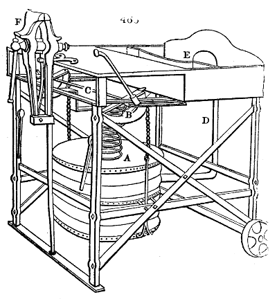
Fig. 466. represents a portable truck forge of a very commodious construction. A is the cylindric leather bellows, pressed down by a helical spring, and worked by means of the handle at B, which moves the horizontal shaft C, with its two attached semicircular levers and chains. D, is the pipe which conducts the blast to the nozzle at E. The hearth may be covered with a thin fire-tile or with cinders. F is a vice fixed to the strong rectangular frame. This apparatus answers all the ordinary purposes of a smith’s forge; and is peculiarly adapted to ships, and to the execution of engineering jobs upon railways, or in the country. The height is 2 feet 6 inches; the length is 2 feet 9 inches; the width 2 feet. Weight about 2 cwt.
FORMIATES; are compounds of formic acid, with the salifiable bases. Many of them are susceptible of crystallization.
FORMIC ACID; (Acide Formique, Fr.; Ameisensäure, Germ.) exists in the bodies of wood ants, associated with the malic or acid of apples. The artificial formation of this animal secretion, is one of the most remarkable triumphs of modern chemistry. If 10 parts of tartaric acid, 14 of black oxide of manganese, 15 of concentrated sulphuric acid, and from 20 to 30 of water be mixed and distilled in a retort, formic acid will be the liquid product; while carbonic acid will be disengaged. It may also be generated from other mixtures. This acid is transparent and colourless, of a pungent sour smell, a strongly acid taste, of specific gravity 1·1168 at 60° F., and may be re-distilled without suffering any change. It contains in its most concentrated form 193⁄4 per cent. of water. The dry acid, as it exists in the formiates, is composed of 32·54 carbon, 2·68 hydrogen, and 64·78 oxygen; or of two volumes carbonic oxide gas, and one volume of vapour of water. It reduces the oxides of mercury and silver to the metallic state. It has not hitherto been applied to any use in the arts.
FORMULÆ, CHEMICAL, are symbols representing the different substances, simple and compound.
Name. Formula. Oxygen = 100. Hydrogen = 1.
Oxygen O 100·000 16·026
Hydrogen H 6·2398 1·000
2H 12·4796 2·000
Nitrogen N 88·518 14·186
2N 177·086 28·372
Phosphorus P 196·155 31·436
2P 392·310 68·872
Chlorine Cl 221·325 35·470
2Cl 442·650 70·940
Iodine I 768·781 123·206
2I 1537·562 246·412
Carbon C 76·437 12·250
2C 152·875 24·500
Boron B 135·983 21·793
2B 271·966 43·586
Silicon Si 277·478 44·469
Selenium Se 494·582 79·263
Arsenic As 470·042 75·329
2As 940·084 150·659
Chromium Cr 351·819 56·383