F. (continued 2)
Reading edition
The celerity with which any fluid passes through the filter depends, 1. upon the porosity of the filtering substance; 2. upon the pressure exercised upon it; and 3. upon the extent of the filtering surface. Fine powders in a liquor somewhat glutinous, or closely compacted, admit of much slower filtration than those which are coarse and free; and the former ought, therefore, to be spread in a thinner stratum and over a more extensive surface than the latter, for equal effect; a principle well exemplified in the working of Dumont’s apparatus, just described.
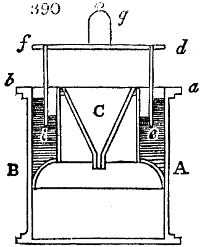
In many cases filtration may be accelerated by the increase of hydrostatic or pneumatic pressure. This happens when we close the top of a filtering cylinder, and connect it by a pipe with a cistern of fluid placed upon a higher level. The pressure of the air may be rendered operative also either by withdrawing it partially from a close vessel, into which the bottom of the filter enters, or by increasing its density over the top of the liquor to be filtered. Either the air pump or steam may be employed to create a partial void in the receiver beneath the filter. In like manner, a forcing pump or steam may be employed to exert pressure upon the surface of the filtering liquor. A common syphon may, on the same principle, be made a good pressure filter, by making its upper leg trumpet-shaped, covering the orifice with filter paper or cloth, and filling the whole with liquor, the lower leg being of such length so as to create considerable pressure by the difference of hydrostatic level. This apparatus is very convenient either on the small or great scale, for filtering off a clear fluid from a light muddy sediment. The pressure of the atmosphere may be elegantly applied to common filters, by the apparatus represented in fig. 390., which is merely a funnel inclosed within a gasometer. The case A B bears an annular hollow vessel a b, filled with water, in which receiver the cylindrical gasometer d, e, f, i, is immersed. The filter funnel C is secured at its upper edge to the inner surface of the annular vessel a b. In consequence of the pressure of the gasometer regulated by the weight g, upon the air inclosed within it, the liquid is equally pressed, and the water in the annular space rises to a corresponding height on the outer surface of the gasometer, as shown in the figure. Were the apparatus made of sheet iron, the annular space might be charged with mercury.
In general, relatively to the application of pressure to filters, it may be remarked, that it cannot be pushed very far, without the chance of deranging the apparatus, or rendering the filtered liquor muddy. The enlargement of the surface is, generally speaking, the safest and most efficacious plan of increasing the rapidity of filtration, especially for liquids of a glutinous nature. This expedient is well illustrated in the creased bag filter now in use in most of the sugar refineries of London. See Sugar.
In many cases it is convenient so to construct the filtering apparatus, as that the liquid shall not descend, but mount by hydrostatic pressure. This method has two advantages: 1. that without much expensive apparatus, any desired degree of hydrostatic pressure may be given, as also that the liquid may be forced up through several filtering surfaces placed alongside of each other; 2. that the object of filtering, which is to separate the particles floating in the fluid without disturbing the sediment, may be perfectly attained, and thus very foul liquids be cleared without greatly soiling the filtering surface.
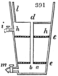
Such a construction is peculiarly applicable to the purification of water, either alone, or combined with the downwards plan of filtration. Of the former variety an example is shown in fig. 391. The wooden or zinc conical vessel is provided with two perforated bottoms or sieves e e, betwixt which the filtering substance is packed. Over this, for the formation of the space h h, there is a third shelf, with a hole in its middle, through which the tube d b is passed, so as to be water tight. This places the upper open part of the apparatus in communication with the lowest space a. From the compartment h h a small air tube l runs upwards. The filtering substance consists at bottom of pebbles, in the middle of gravel, and at the top of fine sand, which may be mixed with coarsely ground bone-black, or covered with a layer of the same. The water to be filtered being poured into the cistern at top, fills through the tube b d the inferior compartment a, from which the hydrostatic pressure forces the water upward through the perforated shelf, and the filtering materials. The pure water collects in the space h h, while the air escapes by the small tube l, as the liquid enters. The stopcock i serves to draw off the filtered water. As the motion of the fluid in the filter is slow, the particles suspended in it have time to subside by their own gravity; hence there collects over the upper shelf at d, as well as over the under one at a, a precipitate or deposit which may be washed out of the latter cavity by means of the stopcock m.
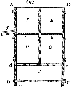
As an example of an upwards and downwards filter, fig. 392. may be exhibited. A B C D is a wooden or metallic cistern furnished with the perforated shelf c d near its under part, upon which a vertical partition is fixed through the axis of the vessel. A semicircular perforated shelf is placed at a, and a second similar one at b. These horizontal shelves rest upon brackets in the sides of the cisterns, so that they may be readily lifted out. The space G is filled with coarse sand, J with moderately fine, and H with very fine. The foul water is poured into the chamber E, and presses through G J H and into the space F; whence it may be drawn by the stopcock f.
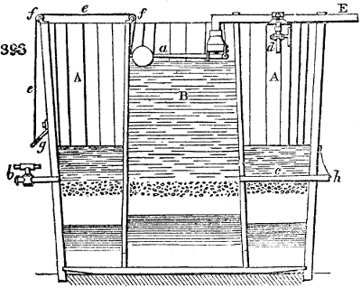
Fig. 393. represents in section a filtering apparatus consisting of two concentric chambers; the interior being destined for downwards filtration, and the exterior for upwards. Within the larger cistern A, a smaller one B is placed concentrically, with its under part, and is left open from distance to distance, to make a communication between the interior cavity and the exterior annular space. These cavities are filled to the marked height with sand and gravel. The inner cylindrical space has fine sand below, then sharper sand with granular charcoal, next coarse sand, and lastly gravel. The annular space has in like manner fine sand below. The foul water is introduced by the pipe E, the orifice at whose end is acted upon by a ball-cock with its lever a; whereby the water is kept always at the same level in the inner vessel. The water sinks through the sand strata of the middle vessel, passes outwards at its bottom into the annular space, thence up through the sand in it, and collecting above it, is let off by the stopcock on the pipe b. When a muddy deposit forms after some time, it may be easily cleared out. The cord e, running over the pulleys f f, being drawn tight, the ball lever will shut up the valve. The stopcock d made fast to the conducting tube E must then be opened, so that the water now overflows into the annular space at A; the tube c, in communication with the inner space B, being opened by taking out the stopper h. The water thereby percolates through the sand strata in the reverse direction of its usual course, so as to clear away the impurities in the space B, and to discharge them by the pipe c h. An apparatus of this kind of moderate size is capable of filtering a great body of water. It should be constructed for that purpose of masonry; but upon a small scale it may be made of stone-ware.
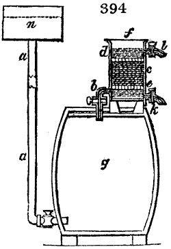
A convenient apparatus for filtering oil upwards is represented in fig. 394. g is an oil cask, in which the impure parts of the oil have accumulated over the bottom. Immediately above this, a pipe a is let in, which communicates with an elevated water cistern n. f is the filter, (placed on the lid of the cask) furnished with two perforated shelves, one at e and another at d; which divide the interior of the filter into three compartments. Into the lower space immediately over the shelf e, the tube b, furnished with a stopcock enters, to establish a communication with the cask; the middle cavity e is filled with coarsely ground charcoal or other filtering materials; and the upper one has an eduction pipe l. When the stopcocks of the tubes a and b are opened, the water passes from the cistern into the oil cask, occupies from its density always the lowest place, and presses the oil upwards, without mixing the two liquids; whereby first the upper and purer portion of the oil is forced through tube b into the filter, and thence out through the pipe l. When the fouler oil follows, it deposits its impurities in the space under the partition c, which may from time to time be drawn off through the stopcock k, while the purer oil is pressed upwards through the filter. In this way the different strata of oil in the cask may be filtered off in succession, and kept separate, if found necessary for sale or use, without running any risk of mixing up the muddy matter with what is clear. According to the height of the water cistern n, will be the pressure, and of course the filtering force. When the filter gets choked with dirt, it may be easily re-charged with fresh materials.
In filtering caustic alkaline lyes through linen or quartz, it is proper to exclude the free contact of air; which is done by inclosing the upper vessel, and attaching a pipe of communication between its cover, and the shoulder of the lower vessel, or recipient of the lyes. In proportion as these flow down, they will displace their bulk of air, and drive it into the top of the upper vessel above the foul lyes.
Many modifications of the above described apparatus are now on sale in this country; but certainly the neatest, most economical, and effective means of transforming the water of a stagnant muddy pool, into that of a crystalline fountain, is afforded by the Royal Patent Filters of George Robins.
FIRE ARMS, Manufacture of. This art is divided into two branches, that of the metallic and of the wooden work. The first includes the barrel, the lock, and the mounting, as also the bayonet and ramrod, with military arms. The second comprises the stock, and in fowling pieces, likewise the ramrod.
1. The Barrel. Its interior is called the bore; its diameter, the calibre; the back end, the breech; the front end, the muzzle; and the closing of the back end, the breech pin or plug. The barrel is generally made of iron. Most military musquets and low-priced guns are fashioned out of a long slip of sheet-iron folded together edge-wise round a skewer into a cylinder, are then lapped over at the seam, and welded at a white heat. The most ductile and tenacious soft iron, free from all blemishes, must be selected for this slip. It is frequently welded at the common forge, but a proper air-furnace answers better, not being so apt to burn it. It should be covered with ashes or cinders. The shape of the bore is given by hammering the cylinder upon a steel mandril, in a groove of the anvil. Six inches of the barrel at either end are left open for forming the breech and the muzzle by a subsequent welding operation; the extremity put into the fire being stopped with clay, to prevent the introduction of cinders. For every length of two inches, there are from two to three welding operations, divided into alternating high and low heats; the latter being intended to correct the defects of the former. The breech and muzzle are not welded upon the mandril, but upon the horn of the anvil; the breech being thicker in the metal, is more highly heated, and is made somewhat wider to save labour to the borer. The barrel is finally hammered in the groove of the anvil without the mandril, during which process it receives a heat every two minutes. In welding, the barrel extends about one-third in length; and for musquets, is eventually left from 3 to 31⁄2 feet long; but for cavalry pistols, only 9 inches.
The best iron plates for gun-barrels are those made of stub iron, that is of old horse-shoe nails welded together, and forged into thin bars, or rather narrow ribands. At one time damascus barrels were much in vogue; they were fashioned either as above described, from plates made of bars of iron and steel laid parallel, and welded together, or from ribands of the same damascus stuff coiled into a cylinder at a red heat, and then welded together at the seams. The best modern barrels for fowling pieces are constructed of stub-nail iron in this manner. The slip or fillet is only half an inch broad or sometimes less, and is left thicker at the end which is to form the breech, and thinner at the end which is to form the muzzle, than in the intermediate portion. This fillet being moderately heated to increase its pliancy, is then lapped round the mandril in a spiral direction till a proper length of cylinder is formed; the edges being made to overlap a little in order to give them a better hold in the welding process. The coil being taken off the mandril and again heated, is struck down vertically with its muzzle end upon the anvil, whereby the spiral junctions are made closer and more uniform. It is now welded at several successive heats, hammered by horizontal strokes, called jumping, and brought into proper shape on the mandril. The finer barrels are made of still narrower, stub-iron slips, whence they get the name of wire twist. On the Continent, barrels are made of steel wire, welded together lengthwise, then coiled spirally into a cylinder. Barrels that are to be rifled, require to be made of thicker iron, and that of the very best quality, for they would be spoiled by the least portion of scale upon their inside. Soldiers’ musquets are thickened a little at the muzzle, to give a stout holding to the bayonet.

The barrels thus made are annealed with a gentle heat in a proper furnace, and slowly cooled. They are now ready for the borer, which is an oblong square bit of steel, pressed in its rotation against the barrel, by a slip of wood applied to one of its flat sides, and held in its place by a ring of metal. The boring bench works horizontally, and has a very shaky appearance, in respect at least of the bit. In some cases, however, it has been attempted to work the barrels and bits at an inclination to the horizon of 30°, in order to facilitate the discharge of the borings. The barrel is held in a slot by only one point, to allow it to humour the movements of the borer, which would otherwise be infallibly broken. The bit, as represented in fig. 395., has merely its square head inserted into a clamp-chuck of the lathe, and plays freely through the rest of its length.
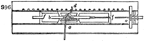
Fig. 396. represents in plan the boring bench for musquet barrels; f f is the sledge or carriage frame in which the barrel is supported; a is the revolving chuck of the lathe, into which the square end of the bit, fig.. 395., is inserted; b is the barrel, clamped at its middle to the carriage, and capable of being pressed onwards against the tapering bit of the borer, by the bent lever c, worked by the left hand of the operative against fulcrum knobs at d, which stand about two inches asunder. Whenever the barrel has been thereby advanced a certain space to the right, the bent end of the lever is shifted against another knob or pin. The borer appears to a stranger to be a very awkward and unsteady mechanism, but its perpetual vibrations do not affect the accuracy of the bore. The opening broach may be of a square or pentagonal form; and either gradually tapered from its thickest part, or of uniform diameter till within two inches of the end, whence it is suddenly tapered to a point.
A series of bits may be used for boring a barrel, beginning with the smallest and ending with the largest. But this multiplication of tools becomes unnecessary, by laying against the cutting part of the bit, slips of wood, called spales, of gradually increasing thickness, so that the edge is pressed by them progressively further from the axis. The bore is next polished. This is done by a bit with a very smooth edge, which is mounted as above, with a wedge of wood besmeared with a mixture of oil and emery. The inside is finished by working a cylindrical steel file quickly backwards and forwards within it, while it is revolving slowly.
In boring, the bit must be well oiled or greased, and the barrel must be kept cool by letting water trickle on it; for the bit, revolving at the rate of 120 or 140 times a minute, generates a great deal of heat. If a flaw be detected in the barrel during the boring, that part is hammered in, and then the bit is employed to turn it out.
Many sportsmen are of opinion that a barrel with a bore somewhat narrowed towards the muzzle serves to keep shot better together; and that roughening its inside with pounded glass has a good effect, with the same view. For this purpose, also, fine spiral lines have been made in their interior surface. The justness of its calibre is tried by means of a truly turned cylinder of steel, 3 or 4 inches long, which ought to move without friction, but with uniform contact from end to end of the barrel. Whatever irregularities appear must be immediately removed.
The outer surface of the barrel is commonly polished upon a dry grindstone, but it is better finished, and less dangerously to the workman, at a turning lathe with a slide rest. If a stone be used, it should be made to revolve at the mouth of a tunnel of some kind, into which there is a good draught to carry off the ferruginous particles. A piece of moist cloth or leather should be suspended before the orifice.
Rifle barrels have parallel grooves of a square or angular form cut within them, each groove being drawn in succession. These grooves run spirally, and form each an aliquot part of a revolution from the chamber to the muzzle. Rifles should not be too deeply indented; only so much as to prevent the ball turning round within the barrel. and the spires should be truly parallel, that the ball may glide along with a regular pace. See infra.
The Parisian gun-makers, who are reckoned very expert, draw out the iron for the barrels at hand forges, in fillets only one-ninth of an inch thick, one inch and a half broad, and four feet long. Twenty-five of these ribands are laid upon each other, between two similar ones of double thickness, and the bundle, weighing 60 pounds, bound with wire at two places, serves to make two barrels. The thicker plates are intended to protect the thinner from the violence of the fire in the numerous successive heats necessary to complete the welding, and to form the bundle into a bar two-thirds of an inch broad, by half an inch thick; the direction of the individual plates relatively to the breadth being preserved. This bar folded flat upon itself, is again wrought at the forge, till it is only half an inch broad, and a quarter of an inch thick, while the plates of the primitive ribands are now set perpendicular to the breadth of the narrow fillet; the length of which must be 15 or 16 feet French (16 or 17 English), to form a fowling piece from 28 to 30 inches long. This fillet, heated to a cherry red in successive portions, is coiled into as close a spiral as possible, upon a mandril about two-fifths of an inch in diameter. The mandril has at one end a stout head for drawing it out, by means of the hammer and the grooves of the anvil, previous to every heating. The welding is performed upon a mandril introduced after each heat; the middle of the barrel being first worked, while the fillets are forced back against each other, along the surface of the mandril, to secure their perfect union. The original plates having in the formation of the ultimate long riband become very thin, appear upon the surface of the barrel like threads of a fine screw, with blackish tints to mark the junctions. In making a double-barrelled gun, the two are formed from the same bundle of slips, the coils of the one finished fillet being turned to the right hand, and those of the other to the left.
The Damascus barrels forged as above described, from a bundle of steel and iron plates laid alternately together, are twisted at the forge several times, then coiled and welded as usual. Fifteen Parisian workmen concur in one operation: six at the forge; two at the boring mill; seven at filing, turning, and adjusting; yet all together make only six pairs of barrels per week, which are sold at from 100 to 300 francs the pair, ready for putting into the stock.
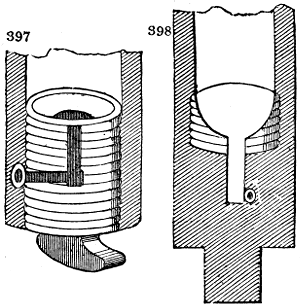
The breeching is of three kinds: the common; the chamber, plug, or mortar, fig. 397.; and the patent, fig. 398. The common was formerly used for soldiers’ musquets and inferior pieces. The second is a trifling improvement upon it. In the patent breeching, the screws do not interfere with the touch-hole, and the ignition is quicker in the main chamber.
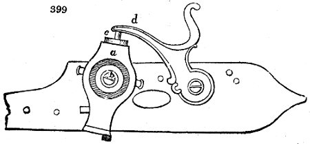
The only locks which it is worth while to describe are those upon the percussion principle, as flint locks will certainly soon cease to be employed even in military musquets. Forsyth’s lock (fig. 399.) was an ingenious contrivance. It has a magazine a, for containing the detonating powder, which revolves round a roller b, whose end is screwed into the breech of the barrel. The priming powder passes through a small hole in the roller, which leads to a channel in communication with the chamber of the gun.
The pan for holding the priming is placed immediately over the little hole in the roller. There is a steel punch c, in the magazine, whose under end stands above the pan, ready to ignite the priming when struck upon the top by the cock d, whenever the trigger is drawn. The punch immediately after being driven down into the pan is raised by the action of a spiral spring. For each explosion, the magazine must be turned so far round as to let fall a portion of the percussion powder into the pan; after which it is turned back, and the steel punch recovers its proper position for striking another blow into the pan.
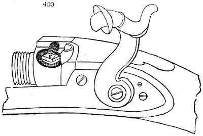
The invention of the copper percussion cap was another great improvement upon the detonating plan. Fig. 400. represents the ordinary percussion lock, which is happily divested of three awkward projections upon the flint lock, namely, the hammer, hammer spring, and the pan. Nothing now appears upon the plate of the lock, but the cock or striking hammer, which inflicts the proper blow upon the percussion cap. It is concave, with a small metallic ring or border, called a shield or fence, for the purpose of enclosing the cap, as it were, and preventing its splinters doing injury to the sportsman, as also protecting against the line of flame which may issue from the touch-hole in the cap nipple. This is screwed into the patent breech, and is perforated with a small hole.
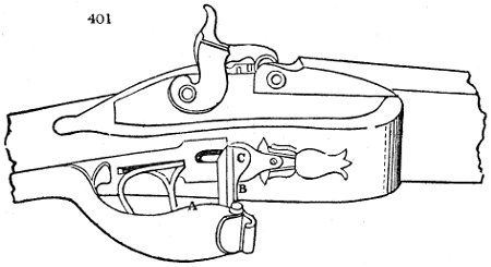
The safety lock of Dr. Somerville is a truly humane invention. Its essential feature is a slide stop or catch, placed under the trigger A, fig. 401. It is pulled forward into a notch in the trigger, by means of a spring B, upon the front of the guard, which is worked by a key C, pressing upon the spring when the piece is discharged. In another safety plan there is a small movable curved piece of iron, A, which rises through an opening B, in the lock-plate C, and prevents the cock from reaching the nipple, as represented in the figure, until it is drawn back within the plate of the lock when the piece is fired.
To fire this gun, two different points must be pressed at the same time. If by accident the key which works the safety be touched, nothing happens, because the trigger is not drawn; and the trigger touched alone can produce no effect, because it is locked. The pressure must be applied to the trigger and the key at the same instant, otherwise the lock will not work.
The French musquet is longer than the British, in the proportion of 44·72 inches to 42; but the French bayonet is 15 inches, whereas the British is 17.
Eng. Dimensions. Fr. Dimensions.
Diameter of the bore 0 ·75 in. 0 ·69. in.
Diameter of the ball 0 ·676 0 ·65
Weight of the ball in oz. 1 ·06 0 ·958
Weight of the firelock and bayonet in libs. 12 ·25 10 ·980
Length of the barrel and bayonet 59 ·00 59 ·72
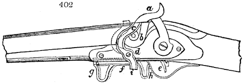
Within these few years a great many contrivances have been brought forward, and several have been patented for fire arms. The first I shall notice is that of Charles Random, Baron de Berenger. Fig. 402. shows the lock and breech of a fowling piece, with a sliding protector on one of the improved plans; a is the hammer, b the nipple of the touch-hole, c a bent lever, turning upon a pin, fixed into the lock-plate at d. The upper end of this bent lever stands partly under the nose of the hammer, and while in that situation stops it from striking the nipple. A slider g f h, connected with the under part of the gun-stock, is attached to the tail of the bent lever at i; and when the piece is brought to the shoulder for firing, the hand of the sportsman pressing against the bent part of the slider at g, forces this back, and thereby moves the end of the lever c forwards from under the nose of the cock or hammer, as shown by the dotted lines. The trigger being now drawn, the piece will be discharged; and on removing the hand from the end g, of the slider f, the spring at h acting against the guard, will force the slider forward, and the lever into the position first described.
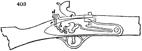
Mr. Redford, gun-maker of Birmingham, proposes a modification of the lock for small fire-arms, in which the application of pressure to the sear spring for discharging the piece is made by means of a plug, depressed by the thumb, instead of the force of the finger exerted against the trigger. Fig. 403. represents a fowling piece partly in section. The sear spring is shown at a. It is not here connected with the trigger as in other locks; but is attached by a double-jointed piece to a lever b, which turns upon a fulcrum pin in its centre. At the reverse end of this lever an arm extends forwards, like that of an ordinary sear spring, upon which arm the lower end of the plug c is intended to bear; and when this plug is depressed by the thumb bearing upon it, that end of the lever b will be forced downwards, and the reverse end will be raised, so as to draw up the end of the sear spring, and set off the piece. For the sake of protection, the head of the plug c is covered by a movable cap d, forming part of a slider e, which moves to and fro in a groove in the stock, behind the breech end of the barrel; this slider e is acted upon by the trigger through levers, which might be attached to the other side of the lock-plate; but are not shown in this figure to avoid confusion. When the piece is brought to the shoulder for firing, the fore-finger must be applied as usual to the trigger, but merely for the purpose of drawing back the slider e, and uncovering the head of the plug; when this is done, the thumb is to be pressed upon the head of the plug, and will thus discharge the piece. A spring bearing against the lever of the slider e, will, when the finger is withdrawn from the trigger, send the slider forward again, and cover the head of the plug, as shown.
It is with pleasure I again advert to the humane ingenuity of the Rev. John Somerville, of Currie. In April, 1835, he obtained a patent for a further invention to prevent the accidental discharge of fire arms. It consists in hindering the hammer from reaching the nipple of a percussion lock, or the flint reaching the steel of an ordinary one, by the interposition of movable safety studs or pins, which protrude from under the false breech before the hammers of the locks, and prevent them from descending to strike. These safety studs or pins are moved out of the way by the pressure of the right hand of the person using the gun only when in the act of firing, that is, when the force of the right hand and arm is exerted to press the butt end of the stock of the gun against the shoulder while the aim is taken and the trigger pulled. In carrying the gun at rest, the proper parts of the thumb or hand do not come over Mr. Somerville’s movable buttons or studs.
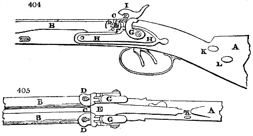
Fig. 404. is a side view of part of a double percussion gun; and fig. 405. is a top or plan view, which will serve to explain these improvements, and show one, out of many, methods of carrying them into effect. A is the stock of the gun; B the barrels; C the breech; D the nipples; E the false breech, on the under side of which the levers which work the safety studs or pins are placed; F is the shield of the false breech; G, triggers; H the lock-plate; and I the hammers: all of which are constructed as usual: a a are the safety studs or pins, which protrude before the shield F, and work through guide pieces on the under side of the false breech. The button piece is placed in the position for the thumb of the right hand to act upon it; but when the pressure of the ball of the right thumb is to produce the movement of the safety studs, it must be placed in or near the position K; and when the heel of the right hand is to effect the movements of the safety studs, the button piece must be placed at L, or nearly so.
In these last two positions, the lever (which is acted upon by the button piece to work the safety studs through a slide) would require to be of a different shape and differently mounted. When the hammers are down upon the nipples after discharging the gun, the ends of the safety pins press against the inner sides of the hammers. When this invention is adapted to single-barrelled guns, only one pin, a, one lever and button piece will be required.
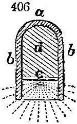
Mr. Richards, gun-maker, Birmingham, patented, in March, 1836, a modification of the copper cap for holding the percussion powder, as represented fig. 406.; in which the powder is removed from the top of the cap, and brought nearer the mouth; a being the top, b the sides, and c the position of the priming. The dotted lines show the direction of the explosion, whereby it is seen that the metal case is opened or distended only in a small degree, and not likely to burst to pieces, as in the common caps, the space between a and c being occupied by a piece of any kind of hard metal d, soldered or otherwise fastened in the cap.
George Lovell, Esq., director of the Royal Manufactory of Arms at Enfield, has recently made a great improvement upon the priming chamber. He forms it into a vertical double cone, joined in the middle by the common apex; the base of the upper cone being in contact with the percussion cap, presents the most extensive surface to the fulminate upon the one hand, while the base of the under one being in a line with the interior surface of the barrel, presents the largest surface to the gunpowder charge, upon the other. In the old nipple the apex of the cone being at its top, afforded very injudiciously the minimum surface to the exploding force.
Guns, Rifling of the Barrels.—The outside of rifle barrels is, in general, octagonal. After the barrel is bored, and rendered truly cylindrical, it is fixed upon the rifling machine. This instrument is formed upon a square plank of wood 7 feet long, to which is fitted a tube about an inch in diameter, with spiral grooves deeply cut internally through its whole length; and to this a circular plate is attached, about 5 inches diameter, accurately divided in concentric circles, into from 5 to 16 equal parts, and supported by two rings made fast to the plank, in which rings it revolves. An arm connected with the dividing graduated plate, and pierced with holes, through which a pin is passed, regulates the change of the tube in giving the desired number of grooves to the barrel. An iron rod, with a movable handle at the one end, and a steel cutter in the other, passes through the above rifling tube. This rod is covered with a core of lead one foot long. The barrel is firmly fixed by two rings on the plank, standing in a straight line on the tube. The rod is now drawn repeatedly through the barrel, from end to end, until the cutter has formed one groove of the proper depth. The pin is then shifted to another hole in the dividing plate, and the operation of grooving is repeated till the whole number of riflings is completed. The barrel is next taken out of the machine, and finished. This is done by casting upon the end of a small iron rod a core of lead, which, when besmeared with a mixture of fine emery and oil, is drawn, for a considerable time, by the workmen, from the one end of the barrel to the other, till the inner surface has become finely polished. The best degree of spirality is found to be from a quarter to half a revolution in a length of three feet.
Military Rifles.—An essential improvement in this destructive arm has lately been introduced into the British service, at the suggestion of Mr. Lovell:
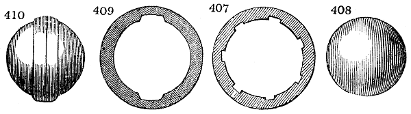
The intention in all rifles is to impart to the ball a rotatory or spinning motion round its axis, as it passes out through the barrel. This object was attained, to a certain degree, in the rifles of the old pattern, by cutting seven spiral grooves into the inside of the barrel, in the manner shewn by fig. 407., the spherical ball, fig. 408., being a little larger than the bore, was driven down with a mallet, by which the projecting ribs were forced into the surface of the ball, so as to keep it in contact with their curvatures, during its expulsion. Instead of this laborious and insecure process, the barrel being now cut with only two opposite grooves, fig. 409., and the ball being formed with a projecting belt, or zone, round its equator, of the same form as the two grooves, fig. 410., it enters so readily into these hollows, that little or no force is required to press it down upon the powder. So much more hold of the barrel is at the same time obtained, that instead of one quarter of a turn, which was the utmost that could be safely given in the old way, without danger of stripping the ball, a whole turn round the barrel, in its length, can be given to the two grooved rifles; whereby a far more certain and complete rotatory motion is imparted to the ball. The grand practical result is, that better practice has been performed by several companies of the Rifle Corps, at 300 yards, than could be produced with the best old military rifles at 150 yards; the soldier being meanwhile enabled to load with much greater ease and despatch. The belt is bevelled to its middle line, and not so flat as shown in the figure.
This mode of rifling is not, however, new in England. In fact, it is one of the oldest upon record; and appears to have fallen into disuse from faults in the execution. The idea was revived within the last few years in Brunswick, and it was tried in Hanover also, but with a lens-shaped (Linsenförmig) ball. The judicious modifications and improvements it has finally received in Mr. Lovell’s hands, have brought out all its advantages, and rendered it, when skilfully used, a weapon of unerring aim, even at the prodigious distance of 700 yards.
Mr. Lovell’s Lock.
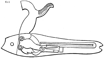
The locks, also, for the military service generally, are now receiving an important improvement by means of his labours, having been simplified in a remarkable manner. The action of the main spring is reversed, as shown by fig. 411.; thus rendering the whole mechanism more solid, compact, and convenient; while the ignition of the charge being effected by percussion powders in a copper cap, the fire of the British line will, in future, be more murderous than ever, as a mis-fire is hardly ever experienced with the fire-arms made at the Royal manufactory, under Mr. Lovell’s skilful superintendence.
FIRE-DAMP; the explosive carburetted hydrogen of coal mines. See Pitcoal.
FIRE-WORKS. (Feux d’artifice, Fr.; Feuerwerke, Germ.) The composition of luminous devices with explosive combustibles, is a modern art resulting from the discovery of gunpowder. The finest inventions of this kind are due to the celebrated Ruggieri, father and son, who executed in Rome and Paris, and the principal capitals of Europe, the most brilliant and beautiful fireworks that were ever seen. The following description of their processes will probably prove interesting to many of my readers.
The three prime materials of this art are, nitre, sulphur, and charcoal, along with filings of iron, steel, copper, zinc, and resin, camphor, lycopodium, &c. Gunpowder is used either in grain, half crushed, or finely ground, for different purposes. The longer the iron filings, the brighter red and white sparks they give; those being preferred which are made with a very coarse file, and quite free from rust. Steel filings and cast-iron borings contain carbon, and afford a more brilliant fire, with wavy radiations. Copper filings give a greenish tint to flame; those of zinc, a fine blue colour; the sulphuret of antimony gives a less greenish blue than zinc, but with much smoke; amber affords a yellow fire, as well as colophony, and common salt; but the last must be very dry. Lampblack produces a very red colour with gunpowder, and a pink with nitre in excess. It serves for making golden showers. The yellow sand or glistening mica, communicates to fire-works golden radiations. Verdigris imparts a pale green; sulphate of copper and sal-ammoniac, a palm-tree green. Camphor yields a very white flame and aromatic fumes, which mask the bad smell of other substances. Benzoin and storax are used also on account of their agreeable odour. Lycopodium burns with a rose colour and a magnificent flame; but it is principally employed in theatres to represent lightning, or to charge the torch of a fury.
Fire-works are divided into three classes: 1. those to be set off upon the ground; 2. those which are shot up into the air; and 3. those which act upon or under water.
Composition for jets of fire; the common preparation for rockets not more than 3⁄4 of an inch in diameter, is: gunpowder, 16 parts; charcoal, 3 parts. For those of larger diameter: gunpowder, 16; steel filings, 4.
Brilliant revolving wheel; for a tube less than 3⁄4 of an inch: gunpowder, 16; steel filings, 3. When more than 3⁄4: gunpowder, 16; filings, 4.
Chinese or Jasmine fire; when less than 3⁄4 of an inch: gunpowder, 16; nitre, 8; charcoal (fine), 3; sulphur, 3; pounded cast-iron borings (small), 10. When wider than 3⁄4: gunpowder, 16; nitre, 12; charcoal, 3; sulphur, 3; coarse borings, 12.
A fixed brilliant; less than 3⁄4 in diameter: gunpowder, 16; steel filings, 4; or, gunpowder, 16; and finely pounded borings, 6.
Fixed suns are composed of a certain number of jets of fire distributed circularly, like the spokes of a wheel. All the fusees take fire at once through channels charged with quick matches. Glories are large suns with several rows of fusees. Fans are portions of a sun, being sectors of a circle. The Patte d’oie is a fan with only three jets.
The mosaic represents a surface covered with diamond shaped compartments, formed by two series of parallel lines crossing each other. This effect is produced by placing at each point of intersection, four jets of fire, which run into the adjoining ones. The intervals between the jets must be associated with the discharge of others, so as to keep up a succession of fires in the spaces.
Palm trees. Ruggieri contrived a new kind of fire, adapted to represent all sorts of trees, and especially the palm. The following is the composition of this magnificent green fire-work: crystallized verdigris, 4 parts; sulphate of copper, 2; sal-ammoniac, 1. These ingredients are to be ground and moistened with alcohol. An artificial tree of any kind being erected, coarse cotton rovings about 2 inches in diameter, impregnated with that composition, are to be festooned round the trunk, branches, and among the leaves; and immediately kindled before the spirits have had time to evaporate.
Cascades, imitate sheets or jets of water. The Chinese fire is best adapted to such decorations.
Fixed stars. The bottom of a rocket is to be stuffed with clay, and one diameter in height of the first preparation being introduced, the vacant space is to be filled with the following composition, and the mouth tied up. The pasteboard must be pierced into the preparation, with five holes, for the escape of the luminous rays, which represent a star.
Composition of fixed stars:—
Ordinary. Brighter. Coloured.
Nitre, 16 12 0
Sulphur, 4 6 6
Gunpowder meal, 4 12 16
Antimony, 2 1 2
Lances, are long rockets of small diameter, made with cartridge paper. Those which burn quickest should be the longest. They are charged by hand without any mould, with rods of different lengths, and are not strangled at the mouth, but merely stuffed with a quick match of tow. These lances form the figures of great decorations; they are fixed with sprigs upon large wooden frame works, representing temples, palaces, pagodas, &c. The whole are placed in communication by conduits, or small paper cartridges like the lances, but somewhat conical, that they may fit endwise into one another to any extent that may be desired. Each is furnished with a match thread fully 11⁄2 inches long, at its two ends.
Composition for the white lances: nitre, 16; sulphur, 8; gunpowder, 4 or 3. For a bluish-white: nitre, 16; sulphur, 8; antimony, 4. For blue lances: nitre, 16; antimony, 8. For yellow: nitre, 16; gunpowder, 16; sulphur, 8; amber, 8. For yellower ones: nitre, 16; gunpowder, 16; sulphur, 4; colophony, 3; amber, 4. For greenish ones: nitre, 16; sulphur, 6; antimony, 6; verdigris, 6. For pink lances; nitre, 16; gunpowder, 3; lampblack, 1. Others less vivid are made with: nitre, 16; colophony, 3; amber, 3; lycopodium, 3.
Cordage is represented in fire-works, by imbuing soft ropes with a mixture of, nitre, 2; sulphur, 16; antimony, 1; resin of juniper, 1.
The Bengal flames rival the light of day. They consist of, nitre, 7; sulphur, 2; antimony, 1. This mixture is pressed strongly into earthen porringers, with some bits of quick match strewed over the surface. These flames have a fine theatrical effect for conflagrations.
Revolving suns, are wheels upon whose circumference rockets of different styles are fixed, and which communicate by conduits, so that one is lighted up in succession after another. The composition of their common fire is, for sizes below 3⁄4 of an inch: gunpowder meal, 16; charcoal, not too fine, 3. For larger sizes: gunpowder, 20; charcoal, not too fine, 4. For fiery radiations: gunpowder, 16; yellow micaceous sand, 2 or 3. For mixed radiations: gunpowder, 16; pitcoal, 1; yellow sand, 1 or 2.
The waving or double Catherine wheels, are two suns turning about the same axis in opposite directions. The fusees are fixed obliquely and not tangentially to their peripheries. The wheel spokes are charged with a great number of fusees; two of the four wings revolve in the one direction, and the other two in the opposite; but always in a vertical plane.
The girandoles, caprices, spirals, and some others have on the contrary a horizontal rotation. The fire-worker may diversify their effects greatly by the arrangement and colour of the jets of flame. Let us take for an example the globe of light. Imagine a large sphere turning freely upon its axis, along with a hollow hemisphere, which revolves also upon a vertical axis passing through its under pole. If the two pieces be covered with coloured lances or cordage, a fixed luminous globe will be formed, but if horizontal fusees be added upon the hemisphere, and vertical fusees upon the sphere, the first will have a relative horizontal movement, the second a vertical movement, which being combined with the first, will cause it to describe a species of curve, whose effect will be an agreeable contrast with the regular movement of the hemisphere. Upon the surface of a revolving sun, smaller suns might be placed, to revolve like satellites round their primaries.
Ruggieri exhibited a luminous serpent pursuing with a rapid winding pace, a butterfly which flew continually before it. This extraordinary effect was produced in the following way. Upon the summits of an octagon he fixed eight equal wheels turning freely upon their axles, in the vertical plane of the octagon. An endless chain passed round their circumference, going from the interior to the exterior, covering the outside semi-circumference of the first, the inside of the second, and so in succession; whence arose the appearance of a great festooned circular line. The chain, like that of a watch, carried upon a portion of its length a sort of scales pierced with holes for receiving coloured lances, in order to represent a fiery serpent. At a little distance there was a butterfly constructed with white lances. The piece was kindled commonly by other fireworks, which seemed to end their play, by projecting the serpent from the bosom of the flames. The motion was communicated to the chain by one of the wheels, which received it like a clock from the action of a weight. This remarkably curious mechanism was called by the artists a salamander.
The rockets which rise into the air with a prodigious velocity, are among the most common, but not least interesting fire-works. When employed profusely they form those rich volleys of fire which are the crowning ornaments of a public fête. The cartridge is similar to that of the other jets, except in regard to its length, and the necessity of pasting it strongly, and planing it well; but it is charged in a different manner. As the sky-rockets must fly off with rapidity, their composition should be such as to kindle instantly throughout their length, and extricate a vast volume of elastic fluids. To effect this purpose, a small cylindric space is left vacant round the axis; that is, the central line is tubular. The fire-workers call this space the soul of the rocket (ame de la fusée). On account of its somewhat conical form, hollow rods, adjustable to different sizes of broaches or skewers, are required in packing the charge; which must be done while the cartridge is sustained by its outside mould, or copper cylinder. The composition of sky-rockets is as follows:—
When the bore is 3⁄4 of an inch; 3⁄4 to 11⁄4; 12⁄3;
Nitre 16 16 16
Charcoal 7 8 9
Sulphur 4 4 4
Brilliant Fire.
Nitre 16 16 16
Charcoal 6 7 8
Sulphur 4 4 4
Fine steel filings 3 4 5
Chinese Fire.
Nitre 16 16 16
Charcoal 4 5 6
Sulphur 3 3 4
Fine borings of cast iron 3 coarser 4 mixed 5
The cartridge being charged as above described, the pot must be adjusted to it, with the garniture; that is, the serpents, the crackers, the stars, the showers of fire, &c. The pot is a tube of pasteboard wider than the body of the rocket, and about one third of its length. After being strangled at the bottom like the mouth of a phial, it is attached to the end of the fusee by means of twine and paste. These are afterwards covered with paper. The garniture is introduced by the neck, and a paper plug is laid over it. The whole is inclosed within a tube of pasteboard terminating in a cone, which is firmly pasted to the pot. The quick-match is now finally inserted into the soul of the rocket. The rod attached to the end of the sky-rockets to direct their flight, is made of willow or any other light wood. M. Ruggieri replaced the rod by conical wings containing explosive materials, and thereby made them fly further and straighter.
The garnitures of the sky-rocket pots are the following:—
1. Stars are small, round, or cubic solids, made with one of the following compositions, and soaked in spirits. White stars, nitre, 16; sulphur, 8; gunpowder, 3. Others more vivid consist of nitre, 16; sulphur, 7; gunpowder, 4.
Stars for golden showers, nitre, 16; sulphur, 10; charcoal, 4; gunpowder, 16; lamp-black, 2. Others yellower are made with nitre, 16; sulphur, 8; charcoal, 2; lamp-black, 2; gunpowder, 8.
The serpents are small fusees made with one or two playing cards; their bore being less than half an inch. The lardons are a little larger, and have three cards; the vetilles are smaller. Their composition is, nitre, 16; charcoal, not too fine, 2; gunpowder, 4; sulphur, 4; fine steel filings, 6.
The petards are cartridges filled with gunpowder and strangled.
The saxons are cartridges clayed at each end, charged with the brilliant turning fire, and perforated with one or two holes at the extremity of the same diameter.
The cracker is a round or square box of pasteboard, filled with granulated gunpowder, and hooped all round with twine.
Roman candles are fusees which throw out very bright stars in succession. With the composition (as under) imbued with spirits and gum-water, small cylindric masses are made, pierced with a hole in their centre. These bodies, when kindled and projected into the air, form the stars. There is first put into the cartridge a charge of fine gunpowder of the size of the star; above this charge a star is placed; then a charge of composition for the Roman candles.
The stars, when less than 3⁄4 of an inch, consist of nitre, 16; sulphur, 7; gunpowder, 5. When larger, of nitre, 16; sulphur, 8; gunpowder, 8.
Roman candles, nitre, 16; charcoal, 6; sulphur, 3. When above 3⁄4 of an inch nitre, 16; charcoal, 8; sulphur, 6.
The girandes, or bouquets, are those beautiful pieces which usually conclude a fire-work exhibition; when a multitude of jets seem to emblazon the sky in every direction, and then fall in golden showers. This effect is produced by distributing a number of cases open at top, each containing 140 sky-rockets, communicating with one another by quick-match strings planted among them. The several cases communicate with each other by conduits, whereby they take fire simultaneously, and produce a volcanic display.
The water fire-works are prepared like the rest; but they must be floated either by wooden bowls, or by discs and hollow cartridges fitted to them.
Blue fire for lances may be made with nitre, 16; antimony, 8; very fine zinc filings, 4. Chinese paste for the stars of Roman candles, bombs, &c.:—Sulphur, 16; nitre, 4; gunpowder meal, 12; camphor, 1; linseed oil, 1; the mixture being moistened with spirits.
The feu grégois of Ruggieri, the son:—Nitre, 4; sulphur, 2; naphtha, 1. See Pyrotechny and Rockets.
The red fire composition is made by mixing 40 parts of nitrate of strontia, 13 of flowers of sulphur, 5 of chlorate of potash, and 4 of sulphuret of antimony.
White fire is produced by igniting a mixture of 48 parts nitre; 131⁄4 sulphur; 71⁄4 sulphuret of antimony; or, 24 nitre, 7 sulphur, 2 realgar; or, 75 nitre, 24 sulphur, 1 charcoal; or, finally, 100 of gunpowder meal, and 25 of cast-iron fine borings.
The blue fire composition is, 4 parts of gunpowder meal; 2 of nitre; sulphur and zinc, each 3 parts.
FISH-HOOKS (Hameçons, Fr.; Fischangeln, Germ.); are constructed with simple tools, but require great manual dexterity in the workmen. The iron wire of which they are made should be of the best quality, smooth, and sound. A bundle of such wire is cut in lengths, either by shears or by laying it down upon an angular wedge of hard steel fixed horizontally in a block or anvil, and striking off the proper lengths by the blows of a hammer. In fashioning the barbs of the hooks, the straight piece of wire is laid down in the groove of an iron block made on purpose, and is dexterously struck by the chisel in a slanting direction, across so much of the wire as may be deemed necessary. A sharp-pointed little wedge is thus formed, whose base graduates into the substance of the metal.
The end of the wire where the line is to be attached is now flattened or screw-tapped; the other end is sharp pointed, and the proper twisted curvature is given. The soft iron hooks are next case-hardened, to give them the steely stiffness and elasticity, by imbedding them in animal charcoal contained in an earthen or iron box; see Case-Hardening; after which they are brightened by heating and agitating them with bran, and finally tempered by exposure to a regulated temperature upon a hot iron plate. Hooks for salt-water fishing are frequently tinned, to prevent them wearing rapidly away in rust. See Tin Plate.
FLAKE WHITE; is the name sometimes given to pure white-lead.
FLAME (Flamme, Fr. and Germ.); is the combustion of an explosive mixture of an inflammable gas or vapour with air. That it is not, as many suppose, combustion merely at the exterior surface, is proved by plunging a fragment of burning phosphorus or sulphur into the centre of a large flame of alcohol. Either of these bodies will continue to burn there with its peculiar light; thus proving that oxygen is mixed with the whole of the burning vapour. If we mix good coal gas with as much atmospheric air as can convert all its carbon into carbonic acid, the mixture will explode with a feeble blue light; but if we mix the same gas with a small quantity of air, it will burn with a rich white flame. In the latter case, the carbonaceous particles are precipitated, as Sir H. Davy first showed, in the interior of the flame, become incandescent, and constitute white light: for from the ignition of solid matter alone can the prismatic rays be emitted in that concentrated union. Towards the interior of the flame of a candle, a lamp, or a gas jet, where the air is scanty, there is a deposition of solid charcoal, which first by its ignition, and afterwards by its combustion, increases in a high degree the intensity of the light. If we hold a piece of fine wire gauze over a jet of coal gas close to the orifice, and if we then kindle the gas, it will burn above the wire with its natural brilliancy; but if we elevate the gauze progressively higher, so as to mix more and more air with it before it reaches the burning point, its flame will become fainter and less white. At a certain distance it becomes blue, like that of the above explosive mixture. Since the combustion of all the constituents is in this case direct and complete, the heat becomes greatest in proportion nearly as the light is diminished. If a few platina wires be held in that dim flame they will grow instantly white hot, and illuminate the apartment. On reversing the order of this experiment, by lowering progressively a flat piece of wire gauze from the summit towards the base of a gas flame, we shall find no charcoal deposited at its top, because plenty of air has been introduced there to convert all the carbon of the gas into carbonic acid, and therefore the apex is blue; but as we descend, more and more charcoal will appear upon the meshes. At the very bottom, indeed, where the atmospheric air impinges upon the gauze, the flame is again blue, and no charcoal can therefore be deposited.
The fact of the increase of the brilliancy and whiteness of flame by the development and ignition of solid matter in its bosom, illustrates many curious phenomena. We can thus explain why olefiant gas affords the most vivid illumination of all the gases; because, being surcharged with charcoal, its hydrogen lets it go in the middle of the flame, as it does in an ignited porcelain tube, whereby its solid particles first get ignited to whiteness, and then burn away. When phosphorus is inflamed, it always yields a pure white light, from the ignition of the solid particles of the snowy acid thus produced.
In the blowpipe, the inner blue flame has the greatest heat, because there the combustion of the whole fatty vapour is complete. The feeble light of burning hydrogen, carbonic oxide, and sulphur, may, upon the principles now expounded, be increased by simply placing in them a few particles of oxide of zinc, slender filaments of amianthus, or fine platina wire. Upwards of twenty years ago, I demonstrated in my public lectures in Glasgow, that by narrowing the top of a long glass chimney over an argand flame either from oil or coal gas, the light could be doubled, at the same cost of material. The very tall chimneys used by the Parisian lampists are very wasteful. I find that with a narrow chimney of half the length of theirs, I can have as good a light, and save 30 per cent. of the oil. Thus the light of a flame may be increased by diminishing its heat, or the intensity of its combustion; and conversely the heat of a flame may be increased by diminishing its light.
FLANNEL; a plain woollen stuff of a rather open and slight fabric.
FLAX. By this term we understand the bast or inner bark of the Linum usitatissimum, which is spun into yarn for weaving linen webs. This plant blossoms in June or July, and commonly ripens its seeds in September. As varieties, we distinguish the spring flax, with short knotty stems, whose seed capsules at the period of maturity, spring open with a perceptible sound; and the close flax, with longer smoother stems, whose capsules give out their seeds only when threshed. The Germans, who have bestowed much attention upon the culture of flax, call the former Klanglein or Springlein, and the latter Dreschlein. This is the kind most commonly grown, but from the difference of climate, soil, and culture, it affords flax of very different qualities. The best ground for this plant is an open, somewhat friable clay, mingled with sand and mould. The early flax is usually sown in the end of April or beginning of May, the late, in June. The seeds ought to be sown thick, whereby the stalks are forced to grow more slender, and the fibres of the bast or harl are not only smoother and finer, but more uniform in length. If the raising of seed be the principal object, the flax must be more thinly sown, whereby it will produce stronger stalks, but more knotty, with shorter fibres, and more productive of tow.
Whenever the flax is ripe, which is shown by the bottom of the stalk becoming yellow, and the leaves beginning to drop off, it must be immediately reaped by pulling it up by the roots. The seeds are still immature, fit merely for the oil press, and not for sowing. When the seed crop is the object, the plant must be suffered to acquire its full maturity; in which case the fibres are less fine and soft.
The flax is carried off the field in bundles to be rippled, or stripped of its seeds, which is done by drawing it by handfuls, through an iron comb with teeth eight inches long, fixed upright in a horizontal beam. When the seeds are more fully ripened, they may be separated by the threshing mill.
The operations next performed upon the flax, will be understood by attending to the structure of the stem. In it, two principal parts are to be distinguished; the woody heart or boon, and the harl (covered outwardly with a fine cuticle), which encloses the former like a tube, consisting of parallel lines. In the natural state, the fibres of the harl are attached firmly not only to the boon, but to each other by means of a green or yellowish substance. The rough stems of the flax after being stripped of their seeds, lose in moisture by drying in warm air, from 55 to 65 per cent. of their weight; but somewhat less when they are quite ripe and woody. In this dry state, they consist in 100 parts of from 20 to 23 per cent. of harl, and from 80 to 77 per cent. of boon. The latter is composed upon the average of 69 per cent. of a peculiar woody substance, 12 per cent. of a matter soluble in water, and 19 per cent. of a body not soluble in water, but in alkaline lyes. The harl contains at a mean 58 per cent. of pure flaxen fibres, 25 parts soluble in water (apparently extractive and albumen), and 17 parts insoluble in water, being chiefly gluten. By treating the harl with either cold or hot water, the latter substance is dyed brown by the soluble matter, while the fibres retain their coherence to one another. Alkaline lyes, and also, though less readily, soap water, dissolve the gluten, which seems to be the cement of the textile fibres, and thus set them free.
The cohesion of the fibres in the rough harl is so considerable that by mechanical means, as by beating, rubbing, &c., a complete separation of them cannot be effected, unless with great loss of time, and rupture of the filaments. This circumstance shows the necessity of having recourse to some chemical method of decomposing the gluten. The process employed with this view is a species of fermentation, to which the flax stalks are exposed; it is called retting, a corruption of rotting, since a certain degree of putrefaction takes place. The German term is rusting. This is the first important step in the preparation of flax. After the retting is completed, the boon of the stalks must be removed by the second operation called breaking, and other subordinate processes. The harl freed from the woody parts contains still a multitude of fibres, more or less coherent, or entangled, and of variable lengths, so as to be ill adapted for spinning. These are removed by the heckle, which separates the connected fibres into their finest filaments, removes those that are too short, and disentangles the longer ones.
I. Of retting.—The fermentation of this process may be either rendered rapid by steeping the flax in water, or slow by using merely the ordinary influence of the atmospheric damp, dews, and rain. Hence the distinction of water-retting and dew-retting. Both may also be combined.
Prior to being retted, the flax should be sorted according to the length and thickness of its stalks, and its state of maturity; the riper the plant, the longer must the retting last. The due length of the process is a point too little studied.
Water-retting.—When flax stalks are macerated in water, at a temperature not too low, fermentation soon begins, evinced in the dingy infusion, by disengagement of carbonic acid gas, and the production of vinegar. If the flax be taken out at the end of a few days, dried, and rubbed, the textile filaments are found to be easily separable from each other. By longer continuance of the steep, the water ceases to be acid, it becomes to a certain degree alkaline, from the production of ammonia, diffuses a fetid odour, from the disengagement of sulphuretted hydrogen gas, along with the carbonic acid; the acetous fermentation being in fact now changed into the putrid. The filaments become yellowish brown, afterwards dark brown and lose much of their tenacity, if the process be carried further.
When the operation is conducted with discernment, the water-retting may be completed by the acetous fermentation alone, as the putrefaction should never be suffered to proceed to any length; because when over-retted, flax is partially rotten, gets a bad colour, and yields a large proportion of tow.
For water-retting, the flax must be bound up in sheaves, placed in layers over each other in the water, or sometimes upright, with the roots undermost. Straw may be put below to keep it from touching the ground, and boards may be laid upon the top, with weights to hold it immersed about a foot beneath the surface, especially when the fermentative gases make it buoyant. As soon as it sinks at the end of the fermentation, it must be inspected at least twice a day, and samples must be taken out to see that no over-retting ensues. A single day too long often injures the flax not a little. We may judge that the retting is sufficient when the harl separates easily from the boon by the fingers, when the boon breaks across without bending, and when several stalks knotted together sink to the bottom upon being thrown into the water. For this completion, a shorter or longer time is required according to the quality of the flax, the temperature, &c., so that the term may vary from five to fourteen days. It may be done either in running or in stagnant water. For the latter purpose, tanks five feet deep are dug in the ground. In stagnant water, the process is sooner finished, but it is more hazardous, and gives a deeper stain to the fibres, than in a stream, which carries off much of the colour. The best place for steeping flax is a pond with springs of water at its bottom; or a tank into which a rivulet of water can be occasionally admitted, while the foul water is let off. For every fresh quantity of flax, the pond should be emptied, and supplied with clear water. Water impregnated with iron, stains flax a permanent colour, and should therefore never be used. After retting, the flax should be taken out without delay, rinsed in clean water, and exposed in an airy situation to dry by the sun.
Rough rippled flax stalks, well seasoned before being retted, and dried afterwards, show a loss of weight, amounting to 20 or 30 per cent., affecting both the boon and the harl. This loss is greater the finer the stems, and the longer the retting. The harl contains, beside the textile filaments, a certain portion of a glutinous cement; but nothing soluble in water. The destruction of the gluten cannot be pushed to the last point by steeping, without doing an essential injury to the filaments.
Dew-retting.—The fetid and noxious exhalations which the water-retting diffuses over an extensive district of country, and the danger of over-retting in that way, especially with stagnant water, are far from recommending that process to general adoption. Dew-retting accomplishes the same purpose, by the agency of the air, dews, and rain, in a much more convenient, though far slower manner. The flax, with this view, should be spread out thin upon meadow or grass lands, but never upon the bare ground, and turned over, from time to time, till the stems, on being rubbed between the fingers, show that the harl and the boon are ready to part. The duration of dew-retting is, of course, very various, from 2 to 6, or 8 weeks, as it depends upon the state of the weather; a moist air being favourable, and dry sunshine the reverse. The loss of weight by dew-retting is somewhat less than by water-retting; and the textile fibres are of a brighter colour, softer and more delicate to the touch.
Mixed retting.—This may be fairly regarded as the preferable plan, the retting being begun in the water, and finished in the air. The flax should be taken out of the steep whenever the acetous fermentation is complete, before the putrid begins, and exposed, for 2 or 3 weeks, on the grass.
II. The breaking is performed by an instrument called a brake. In order to give the wood or boon such a degree of brittleness as to make it part readily from the harl, whereby the execution of this process is rendered easy, the flax should be well dried in the sun, or what is more suitable to the late period of the year, in a stove. Such is often attached to the bakers’ ovens in Germany, and other flax-growing countries. The drying temperature should never exceed 120° F., for a higher heat makes it brittle, easy to tear, and apt to run into tow. Before subjecting the flax to the brake, the stems should be equalized and laid parallel by the hand, and the entangled portions should be straightened with a coarse heckle. The brake has one general construction, and consists of two principal parts, the frame or case, and the sword or beater. In the simplest brakes, the frame e, fig. 412., is a piece of wood cleft lengthwise in the middle, supported by the legs a and c. The sword f, also of hard wood, is formed with an edge beneath, and turns round the centre of motion at q, when seized by the handle h, and moved up and down. As it descends, the sword enters the cleft of the frame, and breaks the flax stalks laid transversely upon it, scattering the boon in fragments.
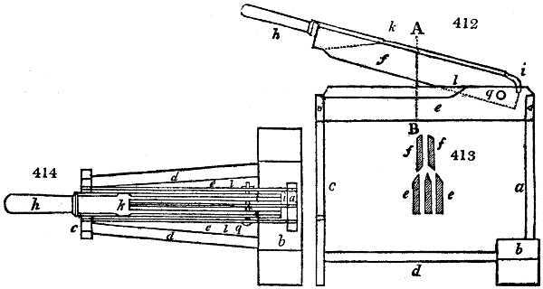
But those hand brakes are more convenient which are provided with a double cleft, or triple row of oblong teeth; with a double sword. This construction will be understood by inspecting figs. 412, 413, 414. Fig. 412. is the section of that side at which the operative sits; fig. 413. is a section in the line A, B, of fig. 412; and fig. 414., the ground plan. The whole machine is made of hard wood, commonly red beech. Two planks, a and c, form the legs of the implement. a is mortised in a heavy block, to give the brake a solid bearing; two stretchers d, bind a and c, firmly together. The frame e consists of three thin boards, which are placed edgewise, and have their ends secured in a and c. The sword f is a piece of wood, so chamfered from i to k, that it appears forklike, and embraces the middle piece of the frame; its centre of motion is the wooden pin q; in front is the handle h, which the operative seizes with the right hand. Both the lathes of the frame, and those of the sword are sharpened, from l to the front end, as is best shown in fig. 413.; but the edges must not be too sharp, for fear of injuring the flax; and, for the same reason, the sword should not sink too far between the lathes of the frame. Such hand-brakes are laborious in use, and often tear the harl into tow. The operative, usually a female, in working the brake, seizes with her left hand a bundle of flax, lays it transversely across the frame, and strikes it smartly with repeated blows of the sword, pushing forwards continually new portions of the flax into the machine. She begins with the roots, turns next round the tips, then goes on through the length of the stalks. Flax is frequently exposed twice to the brake, with a stove drying between the two applications.
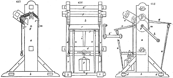
Fig. 415, 416, 417 enlarged (127 kB)
The brake machines afford a far preferable means of cleaning flax than the above hand tools. The essential part of such a machine, consists in several deeply fluted rollers of wood or iron, whose teeth work into each other, and while they stretch out the flaxen stalks betwixt them, they break the wood or boon, without doing that violence to the harl which hand mechanisms are apt to do. The following may be regarded as one of the best constructions hitherto contrived for breaking flax. Fig. 415. is a view of the right side of this machine. Fig. 416., the view from behind, where the broken flax issues from between the rollers. The frame is formed by the two side pillars or walls a, a, which are mortised into the bottom b, b; and are firmly fixed to it by braces. Two transverse rods d, d, secure the base, two others d′ d′′, the sides. In each of these a lateral arm e, is mortised in an oblique direction; a cross bar f, unites both arms. Fig. 417. shows the inside of the left side of the frame, with the subsidiary parts. The three rollers g, i, k, may be made of red beech, with iron gudgeons, and fluted in their length, each of the flutes being 5⁄12 of an inch broad, and 4⁄12ths deep. The large roller g, bears upon the right side, a handle h, which on being turned, sets the whole train in motion. The side partitions a, a, are furnished with brasses in whose round holes l, g, fig. 417., the gudgeons g work. For the extremities of the two smaller rollers, there are at a and e, slots in brasses, as may be seen in fig. 415. Within the partition a, there are movable brasses l, for the pivots of i and k, shewn in fig. 417. Each brass slides in a groove, between two ledges. A strong cord made fast at m to the partition a, runs over the brass of i, next over that of k, then descends perpendicularly, and passes over the cross bar n, fig. 415. and 416. This construction being repeated at both ends of the rollers, the rod n, binds both cords. Against the cross bar d′ of the frame, a lever o is sustained, which lies upon the rod n, and carries a weight p. The farther or nearer this weight hangs towards the end of the lever, it stretches the cord more or less, and presses by means of the brasses l, the rollers i, k, towards the main roller g. A table q, serves for spreading out the flax to be broken, and a second one r, for the reception of the stalks at their issuing from between the rollers. Both tables hang by means of iron hooks to rings of the frame s, t, fig. 415. and 417., and are supported by the movable legs u, u, u, fig. 415. and 416. In using the machine the operative lays an evenly spread handful of flax upon the table q, introduces their root ends with his left hand between the rollers g and i, and turns round the handle h, with the right. The stems are first broken betwixt g and i, then between g and k, and come out upon the table r. The handle is moved alternately forwards and backwards, in order that the flax may be rolled alternately in the same directions, and be more perfectly broken. The boon falls down in very small pieces, and the harl remains expanded in parallel bands. This should be drawn over the points of a heckle, then laid for a couple of days in a cellar to absorb some moisture, and afterwards worked once more through the machine, whereby the flax acquires a peculiar softness.
The advantages of this brake machine are chiefly the following:—
It takes up little room, and from its simplicity is easily and cheaply constructed; it requires no more power to work, than the ordinary hand-brake; it tears none of the filaments, and grinds nothing except the boon, in consequence of the flutings of the rollers going much less deep into each other, than the sword of the hand-brake; it prevents all entanglements of the flax, whence in the subsequent heckling the quantity of short fibres or tow is diminished; and it accomplishes the cleaning of even the shortest flax, which cannot be well done by hand machines.
The comminution of the boon of the stems, which is the object of the breaking process, can however be performed by threshing or beating, although in this way the separation of the woody matter from the textile fibres is much less completely effected.
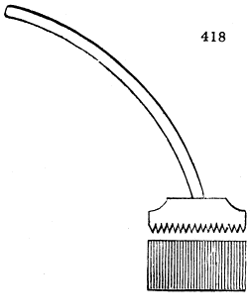
It is the practice in Great Britain, instead of breaking, to employ a water-driven wooden mallet, between which and a smooth stone the flax is laid. In that part of Belgium where the preparation of flax has been studied, the brake is not used, but beating by means of the Bott-hammer, to the great improvement, it is said, of the flax. The Bott-hammer, fig. 418., is a wooden block, having on its under face, channels or flutings, 5 or 6 lines deep, and it is fixed to a long bent helve or handle. In using it, a bundle of the dried flax stalks is spread evenly upon the floor, then powerfully beaten with the hammer, first at the roots, next at the points, and lastly in the middle. When the upper surface has been well beat in this way, it is turned over, that the under surface may get its turn. The flax is then removed, and well shaken to free it from the boon.
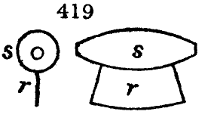
By the brake or the hammer the whole wood is never separated from the textile fibres, but a certain quantity of chaffy stuff adheres to them, which is removed by another operation. This consists either in rubbing or shaking. The rubbing is much practised in Westphalia, and the neighbouring districts. In this process, the operative lays the rubbing apron on a piece of dressed leather, one foot square, upon her knee; then seizes a bundle of flax in the middle with her left hand, and scrapes it strongly with the Ribbe-knife held in her right, fig. 419. This tool, which consists of a wooden handle s, and a thin iron blade r, with a blunt and somewhat bent edge, acts admirably in cleaning and also in parting the filaments, without causing needless waste in flax previously well broken.
The winnowing, which has the very same object as the rubbing, is, however, much more generally adopted than the latter. Two distinct pieces of apparatus belong to it, namely, the swing-stock and the swing-knife. The first consists of an upright board with a groove in its side, into which a handful of flax is so placed that it hangs down over half the surface of the board. While the left hand holds the flax fast above, the right carries the swing-knife, a sabre-shaped piece of wood from 11⁄2 to 2 feet long, planed to an edge on the convex side, and provided with a handle. With this knife the flax is struck parallel to the board, with perpendicular blows, so as to scrape off its woody asperities. The breadth of the swing-knife is an important circumstance; when too narrow it easily causes the flax to twist round it, and thereby tears away a portion of the fibres. When 8 or 10 inches broad, it is found to act best. Knives made of iron will not answer, for they injure the filaments.
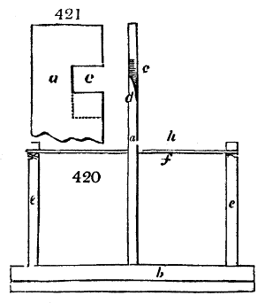
Figs. 420, 421. show the best construction of the swing-stock. The board a has for its base a heavy block of wood b, upon which two upright pins e e, are fixed. The band f, which is stretched between the pins, serves to guide the swing-knife in its movements, and prevent the operative from wounding his feet. The under edge of the groove c, upon which the flax comes to be laid, is cut obliquely and rounded off (see d in fig. 420.); thus we perceive that the swing-knife can never strike against that edge, so as to injure the flax.
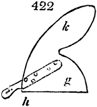
Fig. 422. exhibits the form of a very convenient implement which is employed in Belgium instead of the swing-knife. It is a sort of wooden hatchet, which is not above two lines thick, and at the edge g h is reduced to the thickness of the back of a knife. The fly k gives force to the blow, and preserves the tool in an upright position. The short flat-pressed helve i is glued to that side of the leaf which in working is turned from the swing-stock; and is, moreover, fastened with a wooden pin.
The rubbing and swinging throw off the coarsest sort of tow, by separating and shaking out the shortest fibres and those that happen to get torn. That tow is used for the inferior qualities of sacking, being mixed with many woody fibres.
We may in general estimate that 100 pounds of the stalks of retted flax, taken in the dry state, afford from 45 to 48 pounds of broken flax, of which, in the swinging or scutching, about 24 pounds of flax, with 9 or 10 pounds of scutch tow are obtained. The rest is boon-waste. The breaking of 100 pounds of stalks requires, in the ordinary routine of a double process by hand, about 20 hours; and with the above described machine, from 17 to 18 hours. To scutch 100 pounds of broken flax clean, 130 hours of labour are required by the German swinging method.
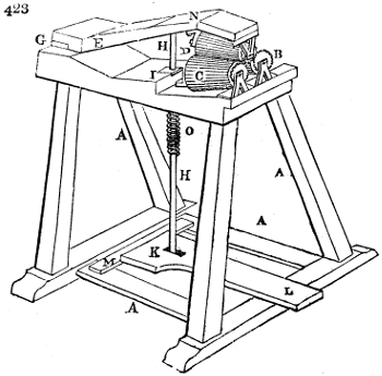
Mr. Bundy obtained a patent in 1819, for certain machinery for breaking and preparing flax, which merits description here. Fig. 423. A A A A, is the frame made either of wood or metal, which supports the two conical rollers B and C. These revolve independently of each other in proper brass bearings. A third conical roller D is similarly supported under the top piece E of the machine. All these rollers are frusta of cones, made of cast iron. Whatever form of tooth be adopted, they must be so shaped and disposed with regard to each other as to have considerable play between them, in order to admit the quantity of flax stem which is intended to be broken and prepared. The upper piece E of the machine which carries the upper conical roller D, is fixed or attached to the main frame A A A A by strong hinges or any other moveable joint at G, and rods of iron or other sufficiently strong material; H H is attached at its upper end by a joint to the top piece E, through a hole near I, and is fixed at its lower end by another joint K to the treadle or lever K L, which turns upon the joint or hinges M. A spring or weight (but the former is preferable for many reasons) is applied to the machine in such manner, that its action will always keep the upper piece E, and consequently the upper roller D, in an elevated or raised position above the rollers B and C, when the machine is not in action; and of course the end L of the treadle will also be raised, which admits of the flax to be worked being introduced between the rollers, viz. over the two lower rollers B, C, and under the upper roller D; such a spring may be applied in a variety of ways, as between the top piece E, and the top or platform of the machine at N; or it may be a strong spiral wire spring, having its upper end fastened to the platform while its lower extremity is fixed to the rod H H, round which it coils as shown at O, or it may be placed under the end L of the treadle; but in every case its strength must be no more than will be just sufficient to raise the upper roller D about two inches from the lower rollers, otherwise it will occasion unnecessary fatigue to the person working the machine.
The manner of using it is as follows: the upper and lower rollers being separated as aforesaid, a small handful of dried flax or hemp stems is to be introduced between them, and held extended by the two hands, while the rollers are brought together by the pressure of the foot upon the treadle L. This pressure being continued, the flax or hemp is to be drawn backwards and forwards by the hands between the rollers, in a direction at right angles to their axes, and eventually withdrawn by pulling with one hand only. The foot is now to be removed until the flax or hemp is again replaced, and each end is this way to be drawn several times through the machine, until such ends are respectively finished.
By a succession of these operations, using the pressure of the foot upon L, each time that the flax or hemp is introduced between the rollers, and regulating such pressure according to the progress of the work, the flax or hemp will soon be sufficiently worked, and the fibre brought into a clean and divided state fit for bleaching; or if it be required to spin it in the yellow state, it may be made sufficiently fine by a longer continuation of the same process, particularly if worked between the smaller ends of the rollers.
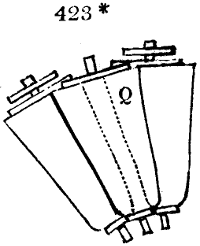
Indeed, the operation may be commenced and continued for some time, with the larger part of the rollers, and finished with their smaller ends; and, in this point of view, the invention of conical rollers will be found both convenient and useful; for as the flutes, grooves, or teeth, vary in their distance from each other at all points between the large and small ends, so it becomes almost impossible for the workman to draw the flax or hemp through such rollers in the same track; and thus the breaking of the boon must be much more irregular, and the fibre will be much more effectually cleansed than it can be by the flutes, grooves, or teeth of cylinders, or other such contrivances formerly employed; because they would probably fall frequently upon the same points of the fibres. If it is intended that the flax shall be bleached before it is spun, then the second part of Mr. Bundy’s invention may be had recourse to, which consists in moving certain trays or cradles in the water, or other fluid used for bleaching the flax or hemp, in the manner following, viz.: The flax or hemp, after having been broken and worked in the machine, should be divided into small quantities of about one ounce each, and these should be tied loosely in the middle with a string, and in this state laid in the trays or cradles, and then be soaked in cold soft water for a day or two, when each parcel should be worked separately, while wet, through a machine, precisely similar to that already described, except only that the rollers should be cylindrical, and made entirely of wood with metal axles, and the teeth, which will be parallel, should be similar in form to those shown in section at Q, fig. 423*. Such operation will loosen the gluten and colouring matter, for the rinsing and wringing which must follow. The flax must then be again disposed in a flat and smooth manner, in such trays or cradles, and once more set to soak in sufficient soft water to cover it, in which a small quantity of soap, in the proportion of about seven pounds of soap to each hundred weight of flax, has been previously dissolved, and in this state it should remain for two or three days longer, and then be finally worked through the machine, rinsed with clear water, and wrung; which will render it sufficiently white for most purposes.
III. The Heckling.—We have already stated that, by the operation of heckling, a three-fold object is proposed: 1. the parting of the filaments into their finest fibrils; 2. the separation of the short fibres which are unfit for spinning; 3. the equable and parallel arrangements of the long filaments. The instrument of accomplishing these objects is a comb-fashioned tool, called the heckle or hackle; a surface studded more or less thickly with metal points, called heckle teeth; over which the flax is drawn in such a way that the above three required operations may be properly accomplished.
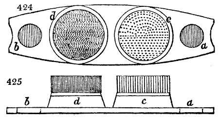
The common construction of the heckle is the following: (see fig. 424.) Fig. 424. is the ground plan, and fig. 425. is the section. Upon an oblong plank a b, two circular or square blocks of wood c and d are fixed, in which the heckle teeth stand upright. To give these a firmer hold they are stuck into holes in a brass or iron plate, with which the upper surface of c and d is covered. Both heckles may be either associated upon one board or separated; and of different finenesses; that is, the teeth of the one may be thinner, and stand closer together; because the complete preparation of the flax requires for its proper treatment, a two-fold heckling; one upon the coarse, and one upon the fine heckle; nay, sometimes 3 or 4 heckles are employed of progressive fineness. The heckle teeth are usually made of iron, occasionally of steel, and from 1 to 2 inches long. Their points must be very sharp and smooth, all at an equal level, and must all graduate very evenly into a cylindrical stem, like that of a sewing needle, without any irregularity. The face of the heckle block must be uniformly beset with teeth, which is done by different arrangements, some persons setting them in a circle, and others in parallel rows; the former being practised in Germany, the latter in England. The coarse heckle is furnished with teeth about one tenth of an inch thick, one and a quarter of an inch long, and tapering from the middle into a very fine point. In the centre of the circular heckle is a tooth planted; the rest are regularly set in 12 similar concentric circles, of which the outermost is 53⁄4 inches in diameter. The fine heckles contain no fewer than 1109 teeth. Instead of making the points of the teeth round, it is better to make them quadrangular, in a rhombus form, in which case the edges serve to separate or dissect the fibres.
The operation of heckling is simple in principle, although it requires much experience to acquire dexterity. The operative seizes a flock of flax by the middle with the right hand, throws it upon the points of the coarse heckle, and draws it towards him, while he holds the left hand upon the other side of the heckle, in order to spread the flax, and to prevent it from sinking too deeply among the teeth. From time to time the short fibres or tow sticking to the teeth are removed. Whenever one half of the length of the strake of flax is heckled, it is turned round to heckle the other half. This process is repeated upon the fine heckle. From 100 pounds of well-cleaned flax, about 45 or 50 pounds of heckled flax may be obtained by the hand labour of 50 hours; the rest being tow, with a small waste in boony particles and dust. The process is continued, till by careful handling little more tow is formed.
Many contrivances have been made to heckle by machinery, but it may be doubted whether any of them as yet make such good work with so little loss as hand labour. In heckling by the hand, the operative feels at once the degree of resistance, and can accommodate the traction to it, or throw the flax more or less deep among the teeth, according to circumstances, and draw it with suitable force and velocity. To aid the heckle in splitting the filaments, three methods have been had recourse to; beating, brushing, and boiling with soap-water, or an alkaline lye.
Beating flax either after it is completely heckled, or between the first and second heckling, is practised in Bohemia and Silesia. Each heckled tress of flax is folded in the middle, twisted once round, its ends being wound about with flaxen threads; and this head, as it is called, is then beat by a wooden mallet upon a block, and repeatedly turned round till it has become hot. It is next loosened out, and rubbed well between the hands. The brushing is no less a very proper operation for parting the flax into fine filaments, softening and strengthening it without risk of tearing the fibres. This process requires in tools, merely a stiff brush made of swines’ bristles, and a smooth board, 3 feet long and one foot broad, in which a wooden pin is made fast. The end of the flax is twisted two or three times round this pin to hold it, and then brushed through its whole length. Well heckled flax suffers no loss in this operation; unheckled, only a little tow; which is of no consequence, as the waste is thereby diminished in the following process. A cylindrical brush turned by machinery might be employed here to advantage.
The boiling of flax with potash lye alone, or with lye and soap, dissolves that portion of the glutinous cement which had resisted the retting, completes the separation of the fibres, and is therefore a good practical means of improving flax. When it is performed upon the heckled fibres, a supplementary brushing is requisite to free it from the dust, soapy particles, &c.