Volume 2 — Chapter XXXV.—WOOD WORKING MACHINERY.
Reading edition
The machines employed in wood working may be divided into 7 classes as follows:
1. Those driving circular saws.
2. Those driving ribbon or band saws.
3. Those driving boring or piercing tools.
4. Those employing knives having straight edges for surfacing purposes and cutting the work to thickness.
5. Those employing knives or cutters for producing irregular surfaces upon the edges of the work.
6. Those employed to produce irregular surfaces on the broad surface of work.
7. Those employed to finish surfaces after they have been acted upon by the ordinary steel cutting tools.
CIRCULAR SAWS.
The thicknesses of circular saws is designated in terms of the Birmingham wire gauge, whose numbers and thicknesses are shown in Fig. 3078, where a Birmingham wire gauge is shown lying upon two circular saws, which show the various shapes of teeth employed upon saws used for different purposes.
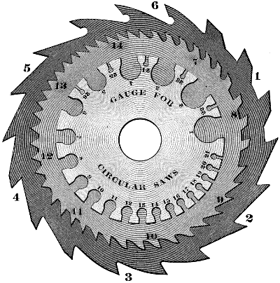
Fig. 3078.
The teeth numbered 1 are for large saws, as 36 inches in diameter, to be used on hard wood. Numbers 2 and 5 are for soft wood and a quick feed. Numbers 3 and 4 are for slabbing or converting round logs into square timber. Number 6 is for quick feeds in large log sawing. Numbers 7, 8, 9 and 10 are for bench saws, or, in other words, saws fed by hand or self-feeding saws. Number 8 is known as the “London Tooth,” because of being used in London, England, on hard and expensive woods. Number 9 is the regular rip-saw tooth for soft woods. Number 10 is the Scotch gullet tooth. Number 11 is for either cross-cutting or rip sawing by circular saws used on soft woods. Number 12, is for large cross-cut saws; the flat place at the bottom of the tooth prevents the teeth from being unnecessarily deep and weak. Number 13 is for cross-cutting purposes generally. Number 14 is for rip sawing on saws of small diameter. It is also used for tortoise-shell, having in that case a bevel or fleam on the front face, and no set to the teeth.
The following table gives the ordinary diameters and thicknesses of circular saws and the diameters of the mandrel hole:
Diameter. Thickness. Size Mandrel Hole.
4 inch. 19 gauge. 3⁄4
5 „ 19 „ 3⁄4
6 „ 18 „ 3⁄4
7 „ 18 „ 3⁄4
8 „ 18 „ 7⁄8
9 „ 17 „ 7⁄8
10 „ 16 „ 1
12 „ 15 „ 1
14 „ 14 „ 1 1⁄8
16 „ 14 „ 1 1⁄8
18 „ 13 „ 1 1⁄4
20 „ 13 „ 1 5⁄16
22 „ 12 „ 1 5⁄16
24 „ 11 „ 1 3⁄8
26 „ 11 „ 1 3⁄8
28 „ 10 „ 1 1⁄2
30 „ 10 „ 1 1⁄2
32 „ 10 „ 1 5⁄8
34 „ 9 „ 1 5⁄8
36 „ 9 „ 1 5⁄8
38 „ 8 „ 1 5⁄8
40 „ 8 „ 2
42 „ 8 „ 2
44 „ 7 „ 2
46 „ 7 „ 2
48 „ 7 „ 2
50 „ 7 „ 2
52 „ 6 „ 2
54 „ 6 „ 2
56 „ 6 „ 2
58 „ 6 „ 2
60 „ 5 „ 2
62 „ 5 „ 2
64 „ 5 „ 2
66 „ 5 „ 2
68 „ 5 „ 2
70 „ 4 „ 2
72 „ 4 „ 2
Circular saws are sometimes hollow ground or ground thinner at the eye than at the rim, to make them clear in the saw kerf or slot with as little set as possible, and therefore produce smooth work while diminishing the liability of the saw to become heated, which would impair its tension. They are also made thicker for a certain portion of the diameter and then bevelled off to the rim.
This is permissible when the work is thin enough to be easily opened from the log by means of a spreader or piece that opens out the sawn piece and prevents it binding against the saw.
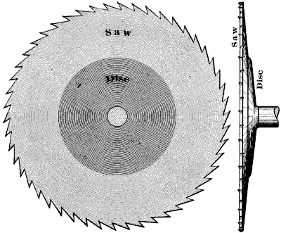
Fig. 3079.
The shingle saw, shown in Fig. 3079, is an example of this kind, the saw bolting to a disc or flange by means of countersink screws.
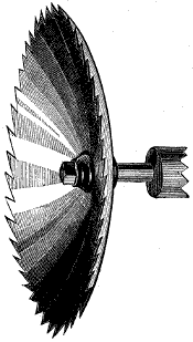
Fig. 3080.
The concave saw shown in Fig. 3080, is employed for barrel heads. The three pieces for a barrel head are clamped together and fed in a circular path, so that the saw cuts out the head at the same time that it bevels the edge.
The advantage of the circular saw lies mainly in the rapidity of its action, whether used for ripping or cross-cutting purposes. In order, however, that it may perform a maximum of duty, it is necessary that the teeth be of the proper shape for the work, that they have the proper amount of set, that they be kept sharp, and that the tension of the saw is uniform throughout when running at its working speed.
The centrifugal force created by the great speed of a circular saw is found to be sufficient to cause it to stretch and expand in diameter. This causes the saw to run unsteadily unless it is hammered in such a way as to have it rim bound when at rest, leaving the stretching caused by the centrifugal force to expand the saw and make its tension equal throughout. The saw obviously stretches least at the eye, and the most at its circumference, because the velocity of the circumference is the greatest, and the amount of stretch from the centrifugal force is therefore the greatest.
It is obvious that the amount of centrifugal force created will depend upon the speed of the saw, and it therefore follows that the hammering must be regulated to suit the speed at which the saw is to run when doing cutting duty, and in this the saw hammerer is guided solely by experience.
A circular saw may have its tension altered and impaired from several causes as follows:
1. From the saw becoming heated, which may occur from the arbor running hot in its bearings, or from the work not being fed in proper line with the saw.
2. From the reduction in diameter of the saw by frequent resharpening of the saw, this reduction diminishing the amount of centrifugal force generated by the saw, and therefore acting to cause the saw to become loose at the eye.
3. From the saw teeth being allowed to get too dull before being sharpened, which may cause the saw teeth to heat, and thus destroy the tension.
4. From stiffening the plate at the throats of the teeth when gumming the saw, an effect that is aggravated by using a dull punch.
5. From the saw teeth having insufficient set, and thus causing the saw to heat.
The methods of discovering the errors of tension in a saw, and the process of hammering to correct them, have already been explained with reference to the use of the hammer on pages from 68 to 70 of volume 2 of this work.
Before hanging a saw on a mandrel, it is necessary to know that the mandrel itself runs true in its bearings or boxes. In a new machine this may be assumed to be the case, but it is better to know that it is so, because if the mandrel does not run true several very improper conditions are set up. First, the saw will run out of true circumferentially, and therefore out of balance, and the high side of the saw will be called upon to do more cutting duty than the low side. Second, the centrifugal force will be greatest on the high side, and the saw will be stiffer, thus setting up an unequal degree of tension. Third, the saw will run out of true sideways, cutting a wider kerf than it should, thus wasting timber while requiring more power to drive.
The collar on the saw arbor should be slightly hollow, so that the saw will be gripped around the outer edge of the collar, and the arbor or mandrel should be level so that the saw will stand plumb. The boxes or bearings of the arbor should be an easy working fit to the journals, and there should be little, or what is better, no end play of the arbor in its bearings.
If a saw arbor becomes heated enough to impair the tension of the saw, it has been hot enough to impair its own truth, and should be examined and trued if necessary.
The most important point in this respect is that the face of the collar against which the saw is clamped should run true, bearing in mind that if it is one hundredth of an inch out of true in a diameter of, say 3 inches, it becomes twenty hundredths or one-fifth of an inch at the circumference of a saw that is 60 inches in diameter.
In cases of necessity, a saw that wabbles from the collar face of the mandrel running out of true, may be set true by means of the insertion of pieces of paper placed between the saw and the face of the collar.
The first thing to do in testing the saw is to take up the end motion of the saw arbor, or if this cannot be done, then a pointed piece of iron or wood should be pressed on the end of the mandrel so as to keep it from moving endways while the saw is being tested.
The saw should be revolved slowly, and a piece of chalk held in the cleft of a piece of wood should be slowly advanced until it meets some part of the face of the saw just below the bottom of the saw teeth.
As soon as the chalk has touched and the saw has made one or two revolutions the chalk should be moved a trifle farther on from the teeth, and another mark made, and then moved on again, and so on, care being taken to notice how much space there is between the high and low sides of the saw. It will be found, however, that the shorter the chalk marks are the more the saw is out of true.
A more correct method is to chalk the face of the saw and use a pointed piece of iron wire of about one-quarter inch in diameter, but in any case the saw should only be touched lightly.
The pieces of paper should be portions of rings or segments, and should extend an equal distance below the circumference of the collar, because the same thickness of paper will alter the saw more in proportion, as it is inserted farther in toward the eye of the saw.
If it should happen that two thicknesses of paper are necessary to true the saw, one should be made about half the length of the other, and the long one may extend farther in toward the eye of the saw. Thus one ring of paper may be an inch deep and the other one-half inch deep.
If but one piece of thin paper is needed, it may be simply a straight piece inserted half way down the collar and trimmed off level with the collar. In placing the paper, the middle of its length should be on that side of the saw that is diametrically opposite to the marks left by the chalk on the face of the saw.
When the saw is trued and is started it will be loose on the outside, but as its speed increases it should stiffen up so as to run true and steadily when running at its working speed.
If the saw is to be tried by actual work, it must be borne in mind that the tension of the saw must be right for its speed when in actual use, and not when running idle. If the machine has belt power enough to maintain the same speed whether the saw is cutting at its usual rate of feed, or whether it is running idle, the tension will not be altered by putting on the feed, but if the saw has been hammered to run at the full speed of the machine when not cutting and the feed is heavy enough to slacken the speed, then the tension of the saw will not be correct for its working speed.
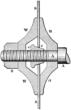
Fig. 3081.
The eyes of small saws are either made to fit the mandrel an easy sliding fit, or else the mandrel is provided with cones to accommodate various sizes of holes, an ordinary construction being shown in Fig. 3081, in which a is the saw arbor, fast on which is the collar b, s representing a section of the saw, w a washer or loose collar, and n the nut for tightening up w. The cone c is screwed upon a and passed through the saw until it just fills the hole, and thus holds the saw true.
In putting on the saw, it should be passed up to the collar, and c screwed home until it binds in the saw eye with enough force to bring the threads of c fairly in contact with those on the mandrel a, but if screwed home too tightly it may spring the saw, especially if the saw is a very thin one.
As c must be removed from the arbor or mandrel every time the saw is changed, the wear on its thread is great, and in time it becomes loose, which impairs its accuracy.
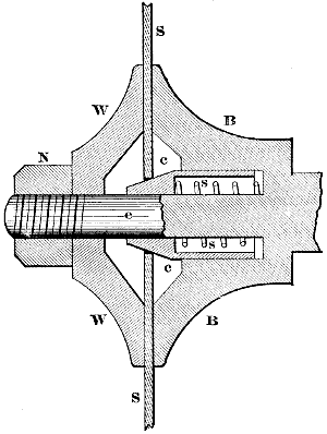
Fig. 3082.
This objection is overcome in the construction shown in Fig. 3082, which is that employed by the S. A. Woods Machine Company. It is seen in the figure that the cone c fits externally in a recess in the collar b, and at the coned end also upon the plain part e of the arbor. The cone is hollow and receives a spiral spring s, s. When the saw is put on it first meets c, and as nut n is screwed up, the saw s and cone are forced along arbor e until the saw meets the face of b, and the clamping takes place. The strength of the spring s is sufficient to hold the saw true, and as the motion of cone c is in this case but a very little, therefore its wear is but little, which makes this a durable and handy device, while the saw cannot be sprung from over-pressure of the cone. Circular saws of large diameter, as from 40 inches upwards, are made a fair sliding fit upon their arbors or mandrels, and are provided with two diametrically opposite pins that are fast in the arbor collar.
The pins should be on diametrically opposite sides of the arbor, and an easy sliding fit to the holes in the saw, but they should not bind tight. Both pins should bear against the holes in the saw, and if both the pins and the holes in the saw are properly located, the saw will pass up to the collar with either side against the arbor collar, or in other words, the saw may be turned around upon the arbor.
If the pins, or either of them, bind in the holes of the saw, and the latter is forced on the arbor, it will spring the saw out of true, and when this is the case care should be taken in making the correction to discover whether it is the pins or the holes in the saw that are wrongly located. If it is the pins, the error will show the same whichever side of the saw is placed next to the arbor collar, while if the error is in the holes, the error will show differently when the saw is reversed on the arbor.
When a saw becomes worn, and its teeth require sharpening, the first thing to do is to joint it, that is to say, bring down all its teeth to the same height, which may be done by holding an emery block or file against it while the saw is running, care being taken to hold the block or file firmly, and to continue the process until the tops of the teeth run true.
The next operation is to gum and sharpen the teeth. Gumming a saw is cutting out the throats, or gullets between the teeth, so as to maintain the height of the tooth, and it follows that on saws that have sharp gullets (or in other words, saws in which the back of one tooth and the face of the next tooth join in a sharp corner), the sharpening process with the file may be made to also perform the gumming.
In the case of teeth of coarse pitch, however, this would entail too much labor in filing, and furthermore, as the height of the teeth increases with the pitch or distance apart of the teeth of circular saws, and as the higher the tooth the weaker it is, therefore coarse pitched teeth are given round gullets so as to strengthen them as much as possible. The gumming of a saw should always be performed before the sharpening, and the sharpening before the setting.
When the sharpening is to be done with the file, the cutting strokes of the file should be in the same direction as the teeth lean for the set, as this leaves a sharper cutting edge, and it follows that the proper plan is to file every other tooth first, going all around the saw, and to then turn the saw around in the vise, and file the remaining teeth.
The height of the teeth and the diameter of the saw will be best maintained by filing the front face of the tooth to bring it up to an edge, but in filing the front face the spacing of the teeth should be kept as even as possible.
If the front face has been filed until a tooth is as widely spaced as those already filed, and the edge is not brought up sharp, then the edge may be brought up by filing the back of the tooth.
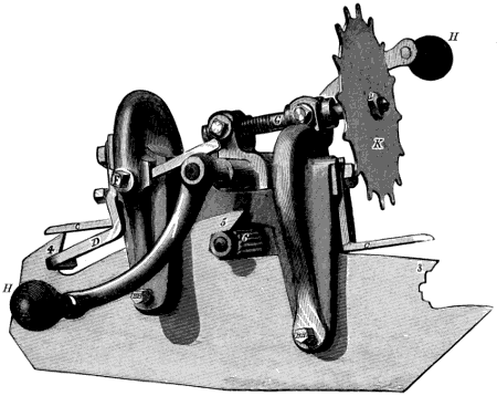
Fig. 3083.
A saw gumming, gulleting or chambering machine to be operated by hand, and constructed by Henry Disston & Sons, is illustrated in Fig. 3083. It consists of a frame spanning the saw, and having screws b b, b b, to adjust to the saw thickness; 4 and 5 are two saw teeth, and 6 the cutter, k is a wheel for the feed screw g, and c and d gauges for regulating position and depth of the gulleting.
The cutter 6 is driven or revolved by means of the handles h h, but an important point in the construction is, that a pawl and ratchet wheel is used to drive the cutter, so that if the handles h h were revolved in the wrong direction, the cutter would not be revolved. This saves the cutter teeth from breakage. The machine is operated as follows:
Run the cutter back by means of screw g as far as necessary, then place the machine on the saw, with the cutter close up in the chamber of the tooth to be gummed.
If the teeth are regular and the same distance apart, start the cutter in any chamber; but if they are irregular, make them even by commencing in the smallest space. After gumming the saw a few times the teeth must become regular. f is a set-screw to regulate the depth of gullet. Fasten the machine to the saw by means of the screws b b, and proceed to gum the first tooth, one of the points of the star being struck at each revolution by a projection on the handle, steadily feeding the cutter until arrested by set-screw f. Remove the machine to the next tooth towards you, after having run the cutter back, and proceed as before until the whole of the teeth are gummed.
The cutter is so arranged as to slide on its axis, and when one portion becomes dull, remove a washer from back to front, and thus present a new sharp cutting surface; and so continue changing the washers until the whole face of the cutter becomes dull.
Set is given to saw teeth in two ways: first, by what is called spring set, which is applied to thin saws and to cross-cut saws; and second, swage set, which is given to thick saws and to inserted teeth. Spring set consists of bending the teeth sideways so as to cause the saw to cut a passageway or kerf, as it is termed, wide enough to permit the saw to pass through the timber without rubbing on its sides.
Swage set consists of upsetting the point of the tooth with a swage, thus spreading it out equally on both sides of the body of the saw plate, as shown at a, Fig. 3084.
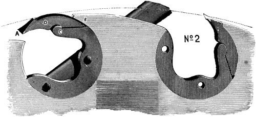
Fig. 3084.
The set of the teeth, whether given by swaging or upsetting, or by spring set, should be equal throughout the saw, so that each tooth may have its proper share, and no more, of duty to perform.
If spring set is employed, it should not extend down more than half the depth of the teeth, and this point is one of considerable importance for the following reasons. The harder the saw is left in the tempering the easier the teeth will break, but the longer they will keep sharp. Now a tooth that is hard enough to break if it is attempted to carry the set down to the root or bottom, will set safely if the set is given to it for one-half its depth only.
If a saw is to be sharpened by filing, it should be made as hard as it can be to file properly, even at the expense of rapidly wearing out the file, because the difference in the amount of work the saw will do without getting dull enough to require resharpening is far more than enough to pay the extra cost of files.
Circular saws with inserted teeth are made of thicker plate than solid saws of corresponding diameters, which is necessary in order that they may securely hold the teeth. The principal difference in the various forms of inserted teeth lies in the method of locking or securing the teeth in the saw.
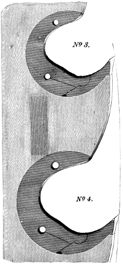
Fig. 3085.
Figs. 3084 and 3085 represent the chisel tooth saws of r. Hoe and Company. The No. 2 tooth is that used on gang edging machines and for bench work. No. 3 tooth is that used in miscellaneous sawing, for hard woods and for frozen lumber. No. 4 is the shape used in the soft and pitchy woods of southern and tropical countries.
The method of inserting the teeth is shown in Fig. 3084 on the left, the pin wrench being shown in position to move the socket whose projection at c carries the tooth d home to its seat and locks it there.
The sockets for the numbers 3 and 4 tooth are, it is seen, provided with a split, which gives to them a certain amount of elasticity that prevents the sockets from getting loose.
Swing-frame saws are made in various forms, generally for cross-cutting purposes or cutting pieces to length.
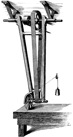
Fig. 3086.
Fig. 3086 represents a swing-frame saw that is mounted over a work bench, and can therefore be used without necessitating carrying the work from the bench. It consists essentially of a frame pivoted at the upper end to the pulley shaft and carrying below a circular saw driven by belt over pulleys on the upper shaft and the saw arbor. In this machine the iron hubs carrying the frame have sockets fitting over the outer diameter of the hanger hubs, so that the frame hangs upon those hubs and not upon the pulley shaft. The advantage of this plan is that the frame joint is relieved of the wear which would ensue were it hung upon the revolving spindle, while at the same time the movement of the joint is so small as to induce a minimum of abrasion. To counterbalance the frame while it is placed out of the perpendicular, there is provided a compensating weight as shown in the engraving.
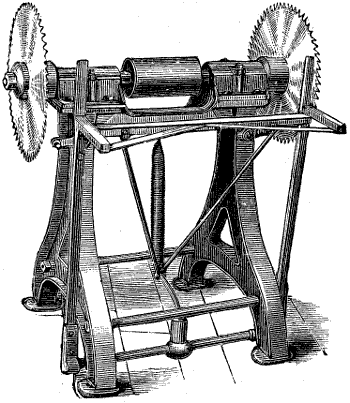
Fig. 3087.
Fig. 3087 represents an example of that class of cutting-off saw bench in which the length of the work is determined by the width apart of the saws.
This machine is constructed by Trevor and Company, and is designed for cutting barrel staves to exact and uniform lengths.
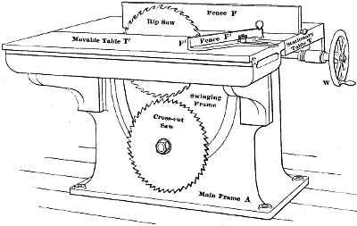
Fig. 3088.
The stave is laid upon the bars of the upright swing-frame (which is pivoted at its lower end), and the latter is vibrated by hand, which may obviously be done both easily and quickly on account of the lightness of the swing-frame and its vertical position. A dimension sawing machine, by G. Richards and Company, is shown in Fig. 3088. This machine is designed for general fine work, such as pattern making, and its general features are as follows:
It carries two saws (a cross-cut and a rip-saw), mounted on a frame that can be quickly revolved by a worm and worm wheel to bring either saw into position as may be required.
There is a fixed table and adjustable fence on one side of the saw, and a movable table and fence on the other.
VOL II. DIMENSION SAWING MACHINE. PLATE XVIII.
Large image (100 kB).
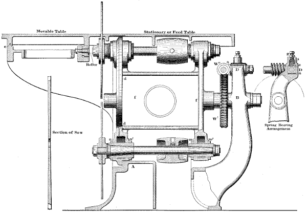
Fig. 3089.
The saws are ground thin at the centre, as shown in Fig. 3089, so that but little or no set need be given to the saw teeth; hence the cutting edges of the teeth are more substantial and true, and as a result the work is cut very smoothly, and if the machine is kept in thoroughly good order, the sandpaper may follow the saw.
In Fig. 3088, a is a substantial box frame, to which is bolted the fixed table t. t′ is the movable table which runs on rollers, and is guided by the ∧ slideway at e. This table the workman pushes to and fro by hand, the work being adjusted upon the table or to the fence, as the case may be. At w is the wheel for swinging the frame to bring the required saw into position.
In Fig. 3089 the worm gear for swinging the saws into position is shown, and also a sectional view of one saw arbor and of the movable table. a is the main frame, and f the disc frame carrying the two saw arbors. The disc d is turned to fit a seating formed in the base, while the other end of the disc frame fits through a substantial bearing b; w′ is the worm wheel, and w′′ the worm for swinging the disc frame. The worm teeth fit closely to the worm wheel teeth, and backlash or play is prevented by means of the spring bearing shown at d, the spiral springs forcing the worm teeth into the worm wheel teeth. Thus a is the bearing for the worm carried in the box c, upon which is the spiral spring whose tension is regulated by the screw g.
The end of the worm is therefore held in a swivel joint that causes it to operate very easily.
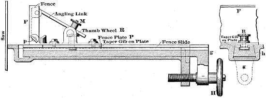
Fig. 3090.
Fence f, Fig. 3088 is for slitting, and is made to swing back for bevel cutting, while f′ is for cross cutting, and is adjustable for angle cutting. Fence f is fitted to a plate p, Fig. 3090, which rests on the table top, and also rests on the long slide g. This slide fits in a beveled way h, and contains a ⊥ groove. A tongue likewise beveled fits in the top of this groove, the tongue being permanently fast to the fence plate. The ⊥ bolt passes through the tongue and fence plate, having at its upper end a milled or knurled thumb wheel r, which when tightened up fastens the fence plate and the slide together.
Upon slacking the thumb wheel r, the fence plate and ⊥ bolt may be readily shifted, setting the fence as near to gauge as possible by hand, and the thumb wheel is then tightened, and the slide (which carries the fence bodily with it) is adjusted by means of the hand wheel h and its screw which threads into a lug from the table.
The fence f is pivoted to plate p at p, and the angling link which holds it in position is secured by a hand nut m.
The front journal of the saw arbor has a double cone, and by means of the nuts n n′, Fig. 3089, can be regulated for fit independently of the back bearing and journal, the latter being also coned and capable of independent adjustment by means of the adjustment nuts m m′.
The countershaft for driving the saw arbors is below the machine, so that the saw that is not in use remains stationary.
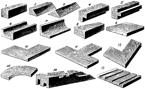
Fig. 3091.
Examples of the work done on this machine are shown in Fig. 3091, the various sections shown being produced by the vertical movement of the saw through the table and the cross movement of the fence. For example, for cutting out a core box, such as shown at 6, small grooves are cut through to remove the bulk of the wood, and the saw marks at the bottom of each saw cut serve as gauge lines for the workman in finishing the circular bore with the gouge, etc.
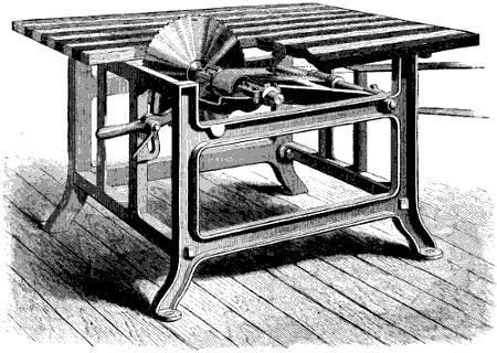
Fig. 3092.
An example in which the table is fixed to the frame and the saw is adjusted for height above the table is shown in Fig. 3092. The saw arbor is here carried in a frame that is pivoted at one end to the main frame, while at the other end is a handle through which passes a locking screw for securing that end of the saw arbor frame to the arc slot shown on the main frame.
In a more expensive form of this machine an adjusting screw is used for regulating the height of the saw, and an iron table is employed instead of a wooden one.
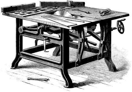
Fig. 3093.
A double saw machine constructed by P. Pryibil is shown in Fig. 3093. In this machine each saw is carried in separate frames, that are pivoted at one end to the main frame and secured at the other to segments, so that either saw may be elevated to the required distance above the work table.
One saw is for ripping and the other for cross cutting, and the arbor of the latter is provided with an adjusting screw operated by the hand wheel shown on the right hand of the machine.
As the saws are on independent arbors, they can be speeded differently to suit different saw diameters, which is an advantage because, as machines of this class are for the lighter classes of work, the ripping saw will rarely be required for work of more than about 3 or 4 inches thick, and a rip saw of large diameter is not therefore necessary.
The cross cut saw however requires to be of larger diameter, as its work includes cross cutting up to 8 or 10 inches diameter, and the saw being larger does not require so high a speed of revolution.
Both saws are provided with ripping gauges and with right and left hand mitre fences, adapted to the application of either short or long work, and provided with length gauges.
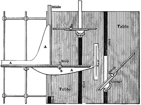
Fig. 3094.
Fig. 3094 illustrates the various gauges in place upon the table of a machine. The table is provided with a slideway, or slot, on each side of the saw, and parallel with it, and also with a slideway at one side of the table. In the figure, the mitre gauge, or gauge for sawing at an angle, is shown in two positions.
The gauge a a a is for cutting work to length, and for cropping the ends at the same time, an extension frame being used, as shown for unusually long work.
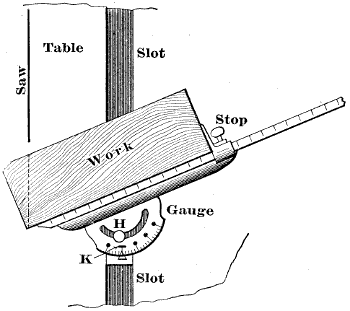
Fig. 3095.
Fig. 3095 illustrates the method of employment of the mitre gauge. The pointer is set to the degree of angle the work is to be cut to, and is fastened to its adjusted position by the set screw h. The stop is set to the required length, and the work is held by hand against the face of the gauge, and at the same time endways against the stop, and the gauge is then moved along the slot, feeding the work to the saw. When the work is sawn and is to be withdrawn, care must be taken to keep the work fair, both against the gauge and against the stop.
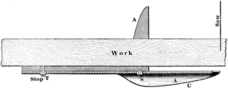
Fig. 3096.
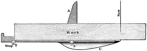
Fig. 3097.
Figs. 3096 and 3097 show the application of the gauges for cropping off the ends of work and cutting it to exact length. There are two stops, s and t, each of which is secured in position by a set screw, and has a tongue that may be thrown over, as occasion may require—thus, suppose it is desired to merely crop off the end of the work—and both stops may be set for the work to rest against as in Fig. 3096, and the end of the work may be cut off or cropped to square it or remove a defective part. Stop s may then be thrown over as in Fig. 3097, and the squared or cropped end of the work rested against stop t, to gauge the length to which the work will be cut. This is a simple and convenient method of cropping and gauging.
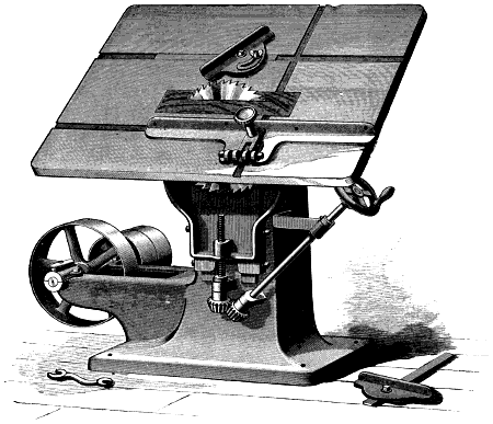
Fig. 3098.
Fig. 3098 represents a circular saw machine, constructed by the Egan Company, in which the table is carried on a vertical slide, and may be raised or lowered by means of the hand-wheel, bevel gears, and screw shown, and may be set at any required angle to the saw for cutting bevels.
The saw arbor or mandrel is carried by the main frame, and is therefore rigidly held.
The fences can be used on either side of the saw, which is very convenient when the table sets out of the level.
BEVEL SAWING MACHINE OR COMBINATION MITRE SAWING MACHINE.
In this machine, which is shown in Figs. 3099, 3100, and 3101, the construction permits of the saw being set so as to revolve at other than a right angle to the work table, which is rigidly secured to the frame of the machine.
Fig. 3099 is a general view, while Figs. 3100 and 3101, are sectional views of the machine.
This machine is constructed by J. S. Graham & Company, and its action may be understood from the following:
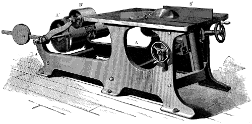
Fig. 3099.
The table is firmly bolted to the frame, and is fitted with the necessary groove slides and fences for rip sawing and cross cutting. It is also provided with a removable piece, which allows the use of wabbling saws, dado heads, etc.
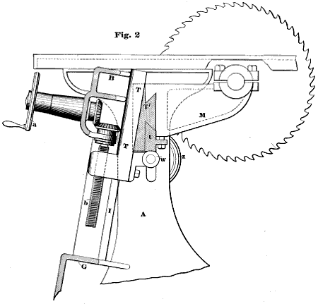
Fig. 3100.
The sides of this machine a, a, Fig. 3099, are cast with an extension for countershaft. Referring now to Figs. 3100 and 3101, the upright piece i, i, with arms b b, and g, g, is bolted to the frame as shown. The arbor frame m, m, is gibbed to t, t, by the circular piece u, and is moved to any angle by the hand wheel z, which operates the worm w, which in turn moves the arbor frame m, m. This arrangement does not require any locking device to hold the saw in position. As the centre upon which the arbor swings is in the intersection of the planes of the saw and table top, the opening in the table needs not be larger than for the ordinary saw. When cutting a mitre the saw takes the position j, Fig. 3101. When cutting at a right angle the saw takes the position j′ and the arbor takes the position p′ n′.
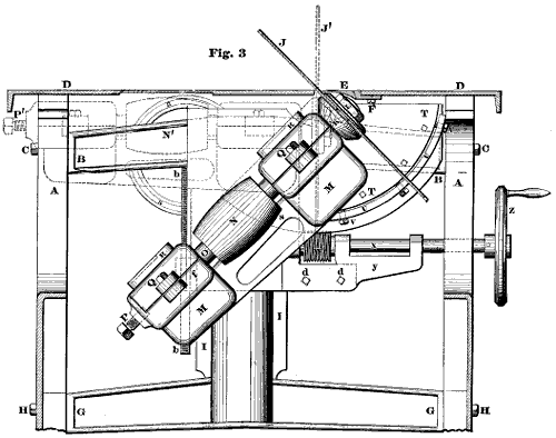
Fig. 3101.
The saw arbor can be raised and lowered by the use of the hand wheel which operates the screw b (Fig. 3100.)
There is an accurate index located in front of the machine in sight of the operator, marked from 0 to 45°.
The iron table is of one piece 4 feet by 3 feet and fitted with the necessary groove slides for ripping and cross cutting gauges. It is also provided with removable piece e, Fig. 3101, allowing the use of dado head, etc. The table is provided with a bevel slitting gauge s′, and cross cut or mitering gauge x′, Fig. 3099, which in connection with the angular adjustment of the saw enables the operator to get every conceivable plain or double mitre ever required. The pulleys a′, b′, are made wide to allow the belt to travel as the saw is inclined. The pulley b′ takes up the slack of the belt. The countershaft and tightener are a part of the machine and can be run wherever a belt can be brought to them.
ROLL FEED CIRCULAR SAWS.
Figs. from 3102 to 3105 represent a roll feed circular saw, by J. Richards.
Fig. 3102 is a side elevation, Fig. 3103 a plan, and Fig. 3104 a cross-sectional view through the rolls.
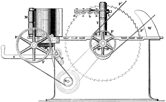
Fig. 3102.
In Fig. 3102, p is the saw-driving pulley, t a stand for carrying the saw guides a, b, c, d, which are adjustable for height by means of the arm whose set screw is shown at u; at w is the spreader for opening out the board after it has been cut by the saw, and thus prevent its binding against the saw and heating it.
The construction of the feed motion is shown in Figs. 3103, 3104, and 3105.
On the saw arbor is the feed cone c, Fig. 3103 having four steps so as to give four rates of feed. This cone connects by belt to feed cone d, whose shaft drives feed pulley e, which drives f by belt connection. f drives two worms shown by dotted lines at h and i, and these drive the worm wheels which drive the feed rolls, one of these worm wheels being shown at k, in the side view, Fig. 3102.
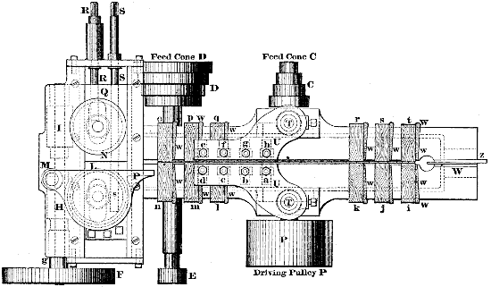
Fig. 3103.
The feed roll l (Fig. 3103) is supplemented by a fence or gauge face p, which guides the work closer up to the saw than would be possible with a roll, and a supplemental roll is provided at m, thus affording a guiding surface for the work from m to the end of p. The stand for guide roll l fits in a slideway, and is adjustable along it by means of the screw s. Similarly the stand for roll n is fed along its slideway by screw r. There are three separate sets of saw guides, all of which are shown in the plan view Fig. 3103, and of these the top ones, a, b, c, d, e, f, g, and h are adjustable by nuts. The front ones, l, m, n, o, p, q, and the back ones, i, j, k, and r, s, t, are adjustable by means of the wedges w. At z is a wedge for adjusting the spreader w so as to keep it close to the saw whatever the diameter of the latter may be.
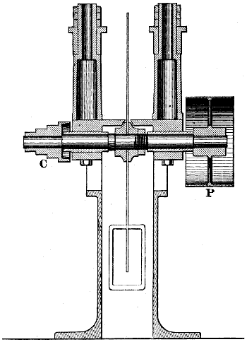
Fig. 3104.
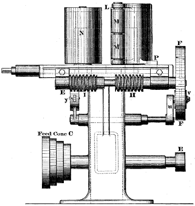
Fig. 3105.
Fig. 3105 is an end view of the machine showing the feed worms h and i, and the belt tightener v, which is carried on the arm u on whose shaft is the weight y, attached to which is the handle x.
SEGMENTAL CIRCULAR SAWS.
A segmental circular saw is one in which the saw is composed of segments secured by screws to a disc, the construction being such as shown in Fig. 3106, in which a is the saw arbor, d the disc, and e, f, g, h, i, j, etc., the segments.
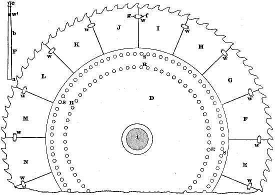
Fig. 3106.
The segments are made of varying thicknesses at the cutting edge, and are tapered for a distance for from 6 to 8 inches inwards from the teeth points. Thus in the figure there is shown at p an edge view of a segment, from a to b being parallel, and from b to c being ground off taper.
The segments are held to the disc by the two sets of screws, r, s, and are further secured at their edges by pieces of copper, as shown at w. Between the edges of the segments there is left a space or opening of about 1⁄16 inch, which is necessary to insure that the segments shall not bind together edgeways, as that might prevent their seating fairly against the face of the disc d.
The seats for these pieces of copper are shaped as shown in the face views at w, and in the edge views at w′, the mouth of the slot being widened on each side, so that riveting up the pieces of copper will prevent the segments from moving sideways.
In fitting in these pieces of copper, it is essential to take care that they do not completely fill the slots, but leave a small opening at each end of the slot, as at f and g in the figure, and in order to do this the copper must be left about 1⁄8 inch narrower than the width of the slot.
If the copper is, in riveting up, brought to bear against the end of the slot, it will twist the segments out of line one with the other, causing the saw to drag, cut roughly and produce bad work.
Left-Hand. Right-Hand.
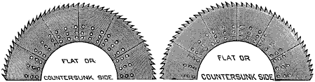
Fig. 3107. Fig. 3108.
Figs. 3107 and 3108 represent portions of segmental saws for cutting veneering. In some of these saws the screw holes are so arranged that the segments can be moved out to maintain the diameter of the saw as it wears.
GANG EDGING MACHINES.
For dressing the edges of planks parallel and to width what are called gang edgers or gang edging machines are employed.
A gang edger consists of an arbor driving two or more circular saws, through which the boards to be edged are fed. Means are provided whereby the distance apart of the saws may be rapidly adjusted while the saws are in motion, so that if a board will not true up to a given width, the saws may be set to cut it to a less one without delay.
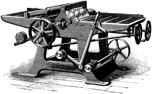
Fig. 3109.
Fig. 3109 represents a self-feeding gang edger, constructed by J. A. Fay & Company, and in which the left-hand saw may be fixed at any required position on the left-hand half of the saw arbor, while the two right-hand ones may be adjusted independently along the arbor, while the machine is running.
At the back of the saw is a feed roll, and above it a pressure roll, whose pressure may be regulated by means of the weight and bar shown at the back of the machine. The object of placing the feed and pressure rolls at the back of the saws, is, that if a board is found to be too narrow for the adjustment of the saws, it may be withdrawn without stopping or reversing the machine, and the saws may be drawn together sufficiently to suit the case.
Fig. 3110 is a plan and Fig. 3111 an edge view of the work table, and show the means of adjusting the saws. a is the saw arbor, and 1, 2, 3, the circular saws. Saw 1 is carried by the sleeve b, which is secured in its adjusted position by the set screw c.
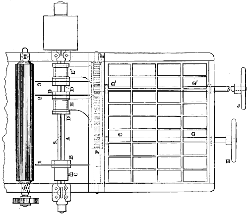
Fig. 3110.
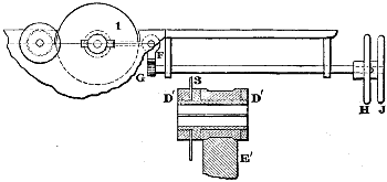
Fig. 3111.
The mechanism for traversing saws 2 and 3 corresponds in design, and may be described as follows:
The arbor a has a spline s to drive the sleeves d, d′, which hold the saws and are carried by arms e, e′, which operate in slideways and have racks f, f′, into which gear pinions whose shafts g, g′, are operated by the hand wheels h, j.
It is obvious that by means of the hand wheels h, j, saws 2 and 3 may be regulated both in their distances apart or in their distances from saw 1, while the machine is in full motion, the bushes or sleeves d and d′ being carried by and revolving in the slide pieces or sliding bearings e and e′ respectively. Now suppose that e′ be moved to the left by hand wheel j, until it abuts against the end of d, at the slide end, and a further movement of d′ will also move d, causing it to operate its pinion and revolve the hand wheel h, hence d and d′ may be simultaneously moved without disturbing their distances apart by operating hand wheel j. On the yoke above the saws is a coarse-figured register plate to enable the setting of the saws to accurate widths apart.
RACK FEED SAW BENCH.
This machine is employed for the purpose of reducing balks or logs into planks of any thickness required. The machine is fixed on the floor of the saw mill, all the gearing being underneath the floor, so that the table may be set level with the floor, which is a great convenience when heavy logs are to be operated upon. The machine consists of a substantial bed plate or frame a, Fig. 3112, carrying the saw and the feed works. The carriage runs on rollers, some of which are fixed to the frame a, and others to the framing timbers b, which are long enough to support the carriage throughout its full length, when the carriage is at either end of its traverse.
VOL. II. RACK‑FEED SAW BENCH. PLATE XIX.
Large image (82 kB).
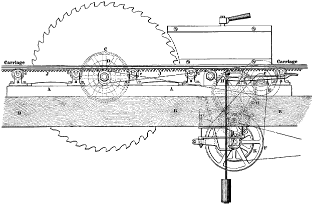
Fig. 3112.
The driving pulley for the saw arbor is shown at c, Fig. 3112, in dotted lines and in Fig. 3113 in full lines. Upon the saw arbor is a cone pulley d, Fig. 3113, for operating the carriage to the feed, the construction being as follows:
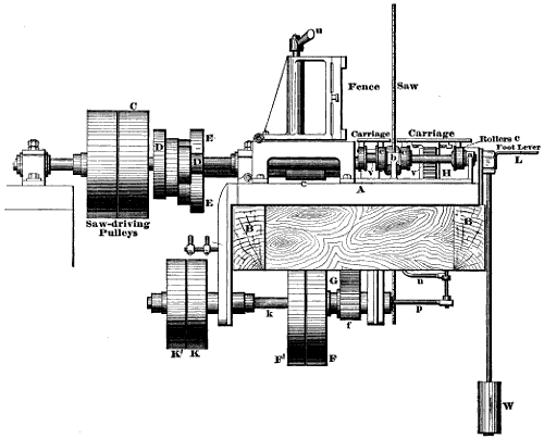
Fig. 3113.
Referring to Figs. 3112 and 3113, cone pulley d connects by a crossed belt to cone pulley e, on whose shaft is a pulley e which drives the pulley f, on whose shaft is the pinion f, which drives the gear g. On the same shaft as g is a pinion g, which drives the gear wheel h, which engages the rack j, on the carriage, and feeds the carriage to the cut. The diameters of pulleys e, f, and of f, g, and g, are proportioned so as to reduce the speed of the cone pulley d, down to that desirable for the carriage feed. But, as there are four steps on the cones d, e, therefore there are four rates of cutting feed or forward carriage traverse, which varies from 15 to 30 feet per minute.
The speed of the saw varies in practice, some running it as slow as 9,000 feet per minute at the periphery of the saw, and others running it as high as 16,000 feet per minute. The latter speed however, is usually obtained when the saws are packed with fibrous packing, which will be explained presently.
The quick return motion for the carriage is obtained as follows:
Referring to Figs. 3113, and 3114, k is a fast and k′ a loose pulley on the shaft k, and receiving motion by belt from a countershaft.
The speed of the fast pulley k is such as to give a return motion to the carriage of about 50 or 60 feet per minute, being about twice as fast as the carriage feed motion.
We have now to explain the methods of putting the respective carriage feed motions into and out of operation, and insuring that both shall not be in gear at the same time.
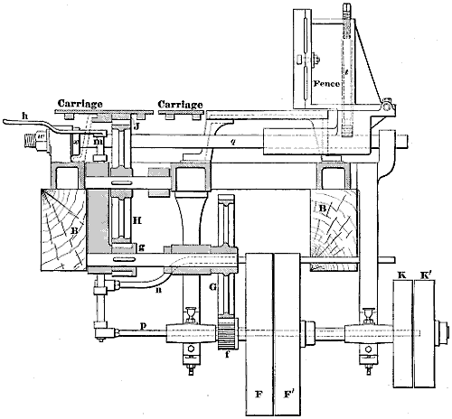
Fig. 3114.
Referring therefore to Figs. 3113 and 3114, suppose the carriage to have completed a feed or cutting traverse, and the operator pushes with his knee the lever or handle h, Fig. 3114, which revolves shaft m, on which is an arm that moves the belt-shifting rod n, thus moving the belt from fast pulley f to loose pulley f′, thus throwing the feed gear out of engagement and causing the carriage to stop. He then presses down the foot lever l, Fig. 3113, which operates the belt-shifting rod p, Fig. 3114, and moves the belt from loose pulley k′, to fast pulley k, which having a crossed belt, operates the pulley f in the reverse direction and traverses the carriage backwards, or on the return motion.
Upon releasing the foot from the lever l, the weight w operates the foot lever l, and the belt is re-shifted from fast pulley k to loose pulley k′, and the carriage stops.
The carriage is formed of iron plates with an open space of about 1⁄2 inch between them, as shown in Fig. 3114, this space forming a race to permit the carriage to travel past the saw. The only connection between the two sections or parts of the table, is a wide plate at the rear end which secures them together, and causes the lighter portion of the table, which is merely driven by the friction of the rollers c, to always travel with the lower or under portion, which is driven by the rack j. In larger machines for the heaviest work, both sections are driven by a rack motion.
The guide motion for the carriage is constructed as follows:
a, a, are brackets placed at intervals along the whole frame work.
These brackets support rollers c, which have flanges on them to prevent any side motion of the carriage, the construction being most clearly seen in Fig. 3113; b being a bearing for the shaft v of the rollers. Each section of the carriage, it will be seen, has two ribs or ways which rest on the rollers, which are arranged four on each shaft v (i.e. two for each section of the carriage).
The fence or gauge against which the face of the work runs is very simply arranged as is shown in Figs. 3113, and 3114, being secured to the shaft q, by a long bolt t, threaded into the top of the fence, and at its lower end abutting against a shoe fitting partly around the top of the shaft q. It is squared at the top to receive a wrench or handle u, and it is obvious that unscrewing the handle releases the fence from shaft q, so that the fence may be moved rapidly by hand across the table to approximate the adjustment of the fence from the saw. The fence having been thus approximately adjusted, and locked to the shaft by means of the handle u, the final adjustment is made by means of the hexagon nut w, on the bed of the shaft nut x, serving as a lock nut, to hold q in its adjusted position.
Fibrous Packing.—The fibrous packing before referred to is composed of hemp, plaited in a four strand plait and inserted in an open-top trough, along the sides of the saw for a distance about two inches less than the radius of the smallest saw the machine uses.
This packing steadies and stiffens the saw, and also affords a means of adjusting its tension, while the saw is running.
Suppose for example, that the saw is rim bound,[47] and the fibrous packing may be rammed tightly to the saw, as near to the saw rim as possible, and less tight as centre of the saw is approached.
This warms the saw, but makes it warmer at the circumference than at the centre, expanding the circumference, and by equalizing the tension, enables the saw to run straight.
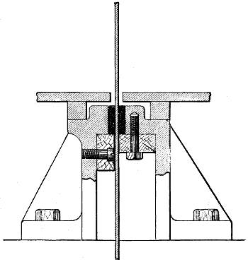
Fig. 3115.
When the packing is to be adjusted, the carriage is run out of the way, and the packing operation is performed by hand, with a caulking tool. The packing and its box, as applied to a rack saw bench is shown in Fig. 3115, by the dark rectangles. By thus packing the saw to guide it and keep it straight, thinner saws may be used, saws 52 inches in diameter, and having a thickness of but 7 or 8 gauge being commonly employed, and in some cases of 9 gauge.
Saws that are thus packed, produce much smoother work.
The packing, it may be observed, is kept well lubricated with oil, and the following is the method of adjusting it.
The side of the saw on which the operator stands is the last to be packed, the packing on the other side being inserted so as bed fairly but lightly against the saw, so as not to spring it, which may be tried with a straight-edge. The packing on the other side is then inserted to also bed fairly against the saw, without springing it, and the saw is run until it gets as warm as it may, from the friction of the packing. If, then, the saw flops from side to side, the outside (circumference) is loose, and the packing is rammed together on both sides of the saw and near the saw arbor or mandrel, care being taken that in ramming the packing the saw is not unduly pressed on either side.
Expert sawyers generally change the packing when the saw is changed, and thus keep for each saw its own packing. The slot or pocket in which the packing lies is about 11⁄4 inches deep, and 1⁄2 inch wide.
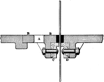
Fig. 3116.
In ordinary circular saw benches or machines the packing comes about up to the level of the table, as shown in Fig. 3116, in which a is a hand hole for putting in and lifting out the plate b, so as to put in or remove the wooden pieces c, d, upon which the packing rests.
VOL. II. PLANTATION SAW MILL. PLATE XX.
Large image (225 kB).
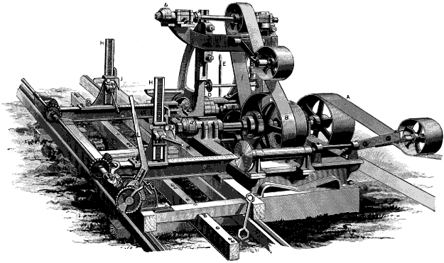
Fig. 3117.
Fig. 3117 represents a saw mill constructed by the Lane & Bodley Company. In this machine two circular saws are employed, the upper one being of small diameter and revolving in the same direction as the log feed. a is the driving pulley for the main saw arbor a, and b the driving pulley for the upper saw arbor b. The carriage feed is obtained by belt from cone pulley c to cone pulley d, on whose shaft is a friction pulley e, which, for the feed motion, is moved by lever e into driving contact with pulley f, whose shaft drives the pinion g, which gears with the rack of the carriage. The three steps on the cones c, d, give three rates of feed, and a quick return motion is given to the carriage by engaging the friction pulley with a wheel not shown in the engraving.
The log to be sawn rests upon the slideway s s’, and is secured thereon by the dogs j, j, which are capable of sliding up or down upon the heads h, h′. When the handles k are raised the slides carrying dogs j are free to be moved up and down h, h′, whereas when handles k are depressed the dogs j are locked and hold the log. The operation is to raise the dog slides to the top of h, h′, set the log up to the faces of h, h′, and then by raising handles k, let the dog slides fall, their weight forcing the dogs into the log, and the depression of k locks the dog slides upon h, h′, respectively.
The log feed is obtained from the lever l, which operates the ratchet wheel t, which drives bevel gears v and w, which operate the screws that slide the heads h, and h′, along the slideways s and s′.
Three rates of log feed are obtained by regulating the amount of motion that can be given to the lever l, the construction being as follows:
In the lever l is a slot in which a stop r can be secured at different heights, and the piece m has four notches. The limit to which l can be moved to the left is until it comes against the stop x, but the limit to which it can be moved to the right is governed by the height of the stop r in the slot in l. If stop r is set at its highest position in the slot, l can be moved to the right until the stop r meets the right hand step on the circumference of m, and a maximum of log feed is given.
TUBULAR SAW MACHINE.
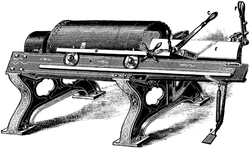
Fig. 3118.
Fig. 3118 represents a tubular saw machine. The saw runs in fixed bearings, the work feeding on the table b, running on ways on a. The work is here obviously sawn to a curve corresponding to that of the circumference of the saw.
CROSS CUTTING OR GAINING MACHINE.
In Figs. 3119 and 3120 is represented a machine constructed for either cross cutting or gaining, the gaining head shown on the machine being replaced by a cross-cut saw when cutting off is to be done.
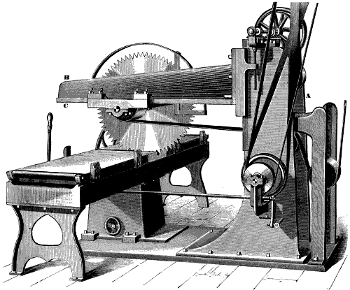
Fig. 3119.
It consists of a vertical column or standard, upon the face of which a slideway a for the arm b, on which is a slideway c, along which the head for carrying the saw arbor traverses.
VOL. II. GAINING OR GROOVING MACHINE. PLATE XXI.
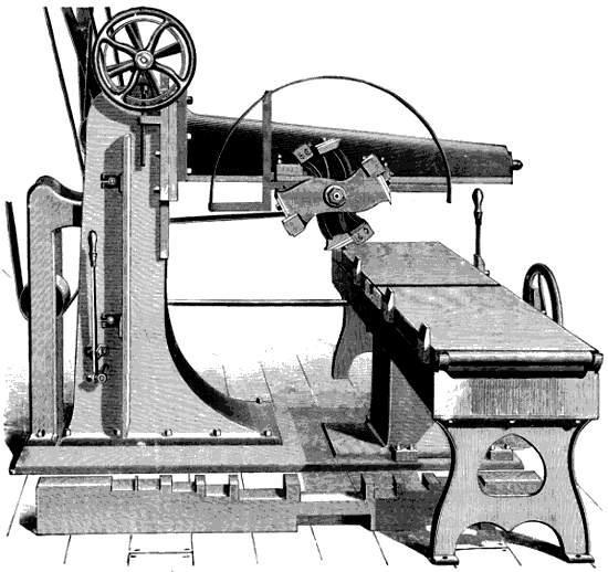
Fig. 3120.
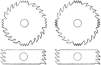
Fig. 3121.
When the saw is to be used, the carriage or work table must be locked in position and adjusted so that the saw will come fair in the groove, provided in the table, but it is not necessary to dog or fasten the work to the table, because the saw itself draws the work over fair against the fence.
When the machine is used for gaining, the work must be dogged fast to the table, so that the work and table may be moved accurately together and the widths apart of the gains kept accurate.
Joshua Oldham’s combination saw for grooving or gaining is shown in Fig. 3121. It consists of two outside saws, such as shown at the top of the figure, and having spur teeth between the ordinary cutting teeth. The tops of the spur or cross-cutting teeth are a little higher than the other teeth, so that they sever the fiber before the ordinary teeth attempt to remove it, and thus produce very smooth work. The inside pieces, shown at the bottom of the figure, go between the two outside saws, if necessary, to make up the required width of gain. They are made 1⁄8 inch thick, with an odd one 1⁄16 inch thick, and will thus make gains advancing in widths by sixteenths of an inch.
SCROLL SAWING MACHINES.
The scroll sawing machine derives its name from the fact that it is particularly fitted for sawing scroll or curved work by reason of the saw (which is a ribbon of steel with the teeth cut on one edge) being very narrow.
The principal points in a scroll sawing machine are to have the saw held under as nearly equal tension as possible throughout the whole of the stroke; to render the machine readily adjustable for different lengths or sizes of saws, to provide it with means of taking up lost motion, and to avoid vibration when the machine is at work.
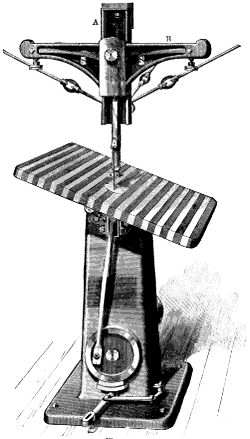
Fig. 3122.
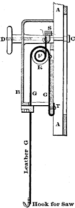
Fig. 3123.
A scroll sawing machine constructed by the Egan Company is shown in Fig. 3122, a sectional view of the saw straining mechanism being shown in Fig. 3123. a, a, is a casting having slides for the head b, which is adjustable upon a to suit different lengths of saws, and is secured in its adjusted position by the bolt c and nut d. To the ends of the springs s, a strip or band of leather is secured, the other end passing around the small step f of a roller r, and being secured thereto. The roller r is so supported that it may rise and fall with the strokes of the saw. A second leather band g is secured at t, passes over the large step of r, and at its lower end hooks to the saw, which is strained by the springs s. This reduces the motion of the springs, and thus serves to equalize their pressure throughout the saw stroke.
The lower end of the saw is gripped in a slide or cross-head that is driven by the connecting rod and crank motion shown in the general view Fig. 3122. The lever shown at the foot of the machine moves the belt to the fast or loose pulley to start or stop the machine, and operates a brake to stop the machine quickly.
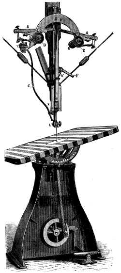
Fig. 3124.
Fig. 3124 represents a scroll saw constructed by H. L. Beach. This machine is provided with a tilting table, which can be set at any angle up to 39 degrees, either to the right or left, the exact angle being indicated by a graduated arc.
The straining device, including the springs, air pump, guide-ways, cross-head and steel bearing, are all attached to the vertical tubular shaft, which is secured to the heavy cast back support by the box e and eccentric lever f. By raising the lever f, the shaft, being balanced, is free to move up or down to suit any length of saw.
At the same time, the steel bearing l forms a support for the back and sides of the saw, and can be raised or lowered to suit any thickness of work.
The under guide-ways are so constructed that their expansion by tightening does not tighten the cross-head. Instead of the ordinary tight and loose pulleys, the crank shaft carries a friction pulley and combination brake by which the saw is stopped or started instantly, by a single motion of the foot.
This leaves the hands entirely free, and saves considerable time in stopping and starting.
The lower end of the saw is held by a steel clamp; when the saw breaks it can be used again by filing a notch. Both ends of the saw are arranged to take up lost motion and wear.
Any desired strain from 10 to 75 pounds can be given to the saw, and the strain is equal at all points of the stroke.
BAND SAWING MACHINES.
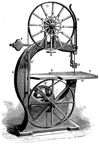
Fig. 3125.
The simplest form of band sawing machine is that in which the work is fed to the saw by hand, a machine of this class, constructed by J. A. Fay & Co., being shown in Fig. 3125. It consists of a standard or frame a, carrying the saw-driving wheel b, and the upper wheel c, the saw being strained upon these two wheels. The lower wheel runs in fixed bearings, while the bearing of the upper wheel is carried in a slide provided in the frame, being operated in the slide by a screw, whose hand wheel is shown at e, so that it may be suited for different lengths of saws.
The bearing of the upper wheel is so arranged that the tension placed on the saw may be governed by a weighted lever f, which enables the upper bearing to lower slightly, so that if a chip should fall between the saw and the lower wheel, it may not overstrain, and therefore break the saw.
At j, is a bar carrying a guide g, which sustains the saw against the pressure of the cut, a similar guide being placed below the table t, at g′. This latter guide is fixed in position, whereas the upper one, g, is adjustable for height from the work table, so that it may be set close to the top of the work, let the height of the latter be what it may. g′′ is a guide and shield for the saw at the back of the machine, and h is a shield to prevent accident to the workman, in case the saw should break.
Band saws are ribbons of steel, brazed together at their ends and having their teeth provided on one edge. The widths of band saws vary from 1⁄16 inch to 8 inches, and their thicknesses from gauge 18 to 22 gauge, according to width.
The advantage of the band saw lies in that it may be run at high velocity, may be made thin, and its cutting action is continuous.
As a band saw is weak, it is desirable to have the teeth as short as possible and leave enough room for the sawdust, so that it shall not pack in the teeth.
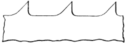
Fig. 3126.
In a circular saw, the centrifugal force acts to throw the sawdust out, while in a frame saw, the backward motion of the saw acts to clear the teeth of the dust, whereas in a band saw the dust is apt to pack in the teeth while they are passing through the work. The remedy is to space the teeth widely, thus giving room for the dust without having a deep tooth, an ordinary form of tooth being shown in Fig. 3126.
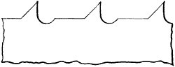
Fig. 3127.
A stronger form of tooth is shown in Fig. 3127, the tooth gullets being well rounded out, and the teeth shallow at the back, while having ample room in front for the dust.
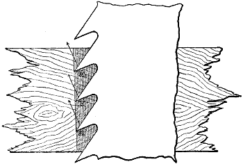
Fig. 3128.
In determining the shapes of the teeth of band saws, we have the following considerations:
One of the principal objects is to have the back edge of the saw bear as little as possible upon the saw guide, and as the feed tends to force that edge against the guide, we must so shape the teeth as to relieve the back guide as much as the circumstances will permit. This may be done by giving to the front faces of the teeth as much rake as the nature of the work will permit. Thus, in Fig. 3128, it will be seen that from the front rake, or hook of the teeth, as it is commonly called, there is a tendency for the cut to pull the saw forward, this tendency being caused by the pressure, on the teeth in the direction of the arrows, and obviously acting to prevent the saw from being forced against the back guide.
For sawing soft woods, such as pine, the teeth may be given a maximum of front rake or hook, whereas for hard woods, the front faces must be made to stand at very nearly a right angle to the length of the blade, and the feed must therefore be lighter, in order to relieve the back edge of the saw from excessive contact with the back guide, which would not only rapidly wear the guide, but acts to crystallize the edge of the saw and cause it to break.
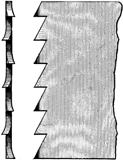
Fig. 3129.
The set of the teeth of band saws is given in two ways, i. e. by spring set, which consists of bending each alternate tooth sideways, as in Fig. 3129, or by swage set (upsetting or spreading the points of all the teeth), a plan that may be followed with advantage for all saws thicker than about 20 gauge.
Spring set is given either by bending, or by hammer blows, and swage set either by blows or by compression. In spring set, each tooth cuts on one side, and there is consequently a pressure tending to bend the tooth sideways, and break it at the root, whereas in spread set, the tooth cuts on both sides equally. As the front faces of band saw teeth are filed straight across, as in Fig. 3129, and are not given any fleam for any kind of woodwork, the set, whether spring or a spread, should be equal in amount for every tooth, and the pitch and depth of the teeth should be exactly alike, so that no one tooth will take more than its proper share of the cut.
The bend or set of the tooth in spring set saws, should not extend more than half way down the depth of the tooth, which will make the set more uniform and save tooth breakage, it being borne in mind, that a tooth hard enough to break if the set extends down to the root, will set easily if it extends half way down only, and that a saw may be soft enough to file, and of a proper temper, and yet break if the spring set is attempted to be carried too far down the tooth.
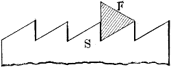
Fig. 3130.
If as in the case of fine pitched teeth, the teeth are filed with a triangular or three square file but little front rake or hook can be given, without pitching the teeth widely. This is shown in Fig. 3130, in which s, is the section of a saw, and f, a section of a three square file. The front faces have no rake, and the file is shown as acting on both faces.
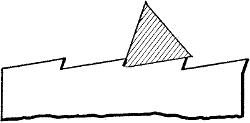
Fig. 3131.
In Fig. 3131, we have the same pitch of teeth, but as the file is canted over, so as to give front rake or hook to the tooth, the tooth depth is reduced, and there is insufficient room for the sawdust. In order, therefore, to give to the teeth front rake, and maintain their depth while keeping the pitch fine, some other than a three square file must be used.
The principal defect of the band saw is its liability to break, especially in band saws of much width, as say 3 inches and over. A saw that is 6 inches wide will ordinarily break by the time it has worn down to a width of 4 inches. Now for heavy sawing it is necessary that wide saws be used, in order to get sufficient driving power without over-straining the saw.
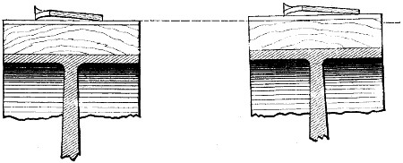
Fig. 3132. Fig. 3133.
The causes of this saw breakage are as follows:
In order that the saw may be regulated to run on the required part of the upper wheel, and lead true to the lower wheel, it is necessary that the upper wheel be canted out of the vertical, and band sawing machines are provided with means by which this may be done. If the upper wheel were set level, as in Fig. 3132, the saw itself would be held out of level, and the toothed edge would be more tightly strained than the back edge. Furthermore the middle of the saw cannot bed itself perfectly to the wheel. Furthermore, the velocity of the toothed edge would be greater than that of the back edge because of its running in a circle of larger diameter when passing over the wheels.
This is to some extent remedied by setting the wheel out of the vertical, as in Fig. 3133, in which case the two edges will be more equally strained, and have a more equal velocity while passing over the wheels.
There will still however, be an unequal strain or tension across the saw width, and it is found that unless the saw is made what is known as loose,[48] it is liable to break, and will not produce good work. It is to be observed however, that the above may be to a great extent, and possibly altogether, overcome by means of having the rim face of the wheel, or of both wheels, curved or crowned in their widths, so that the saw will be in contact with the face of the wheel, nearly equally across the full saw width. This would also cause the saw to run in the middle of the wheel width, and thus enable the alignment of the saw to be made without requiring the upper wheel to be set out of level.
RE-SAWING BAND SAW MACHINE.
A re-sawing machine is one used to cut lumber (that has already been sawn) into thinner boards. Fig. 3134 represents a band saw machine, constructed by P. Pryibil, having a self-acting feed motion, consisting of four feed rolls, all of which are driven, and two small idle rolls, which are so arranged as to guide the last end of the stuff or work after it has left the driven rolls.
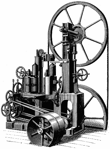
Fig. 3134.
Four rates of feed are provided, and the upper wheel can be set at the required angle from a perpendicular while the machine is in motion.
The upper guide wheel, and the mechanism by which it is carried, is counterbalanced by a weight that hangs within the column or main frame, and is therefore out of sight.
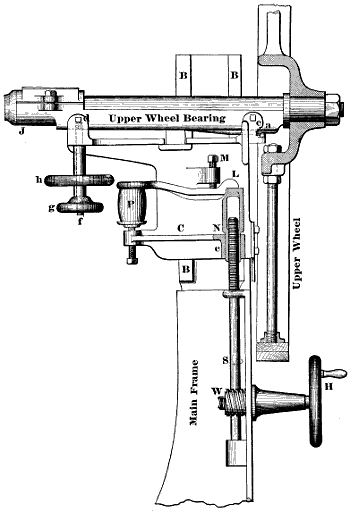
Fig. 3135.
The construction of the parts by means of which the upper wheel is adjusted in height to regulate the tension of the saw, and which also cants the wheel out of the vertical, is shown in Fig. 3135, which represents a portion of the main frame or column, on which is a slideway b, for the slide c, which carries the bearing for the upper wheel.
The method of moving the slide c for moving the upper wheel to adjust the saw tension is as follows:
By means of the handle h and the worm and worm wheel at w, the shaft s is revolved. The upper end of s is threaded into the nut n, which is capable of end motion in its bearing at e, and which abuts against the lever l, the latter abutting against the end of the screw m, and acting at its other end on the rubber cushion p. Now suppose that s be revolved in the direction denoted by the arrow, and the effect will be to raise the nut n. This effect will be transferred through the screw m to the slide c, which will rise up on b, carrying with it the upper wheel bearing and wheel.
When the upper wheel receives the strain of the saw, then the continued revolution of shaft s will cause the nut n to lift endways in its bearing e, the screw m acting as a fulcrum to cause the lever l to compress the rubber cushion p. The amount of tension on the saw is tested by springing it sideways with the hands. Now suppose the saw to be properly strained, and that a piece or chip of wood accidentally gets between the saw and the lower wheel, and the result will be that the slide c will (from the extra strain caused by the chip) move down on its slideway b, which it is capable of doing, because the long arm of the lever l can move down, compressing p, and this will prevent the saw from breaking.
To cant the wheel for leading the saw true to the lower wheel, the following means are provided:
The upper wheel bearing rests on the fulcrum at a, and is guided sideways by the screws c and d. At f is a stud threaded into the bottom half of the upper wheel bearing, the wheels g and h threading upon f. The weight of the upper saw wheel endeavors to lift the end j of the wheel bearing, and wheel h determines how much it shall do so, while wheel g acts as a check nut to lock the adjustment.
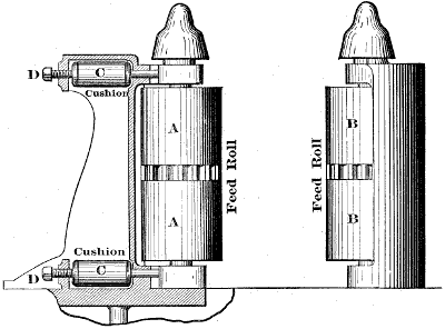
Fig. 3136. Fig. 3137.
The feed rolls are carried in slides which are operated in slideways by means of screws, and the two back rolls, or those nearest to the column are maintained vertical. The two front ones, however, are provided with means by which they may adjust themselves to bear along the full depth of the work, notwithstanding that it may be taper. The construction by means of which this is accomplished is shown in Figs. 3136 and 3137, in which a is front and b a back feed roll. The bearings of feed roll a abut against rubber cushions c, c, whose amount of compression is regulated by the set screws d, d.
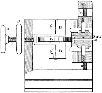
Fig. 3138.
The construction of the saw guides is shown in Fig. 3138, which is a plan view partly in section. s s are hardened steel plates set up to the saw by means of studs whose nuts are shown at n n. w is a friction wheel which supports the saw against the thrust caused by the work feeding to the saw. The adjustment of the wheel w to the saw is obtained by means of the wheel h.
The hand wheel h operates the screw r r, that adjusts the wheel w to the saw, the wheel j serving to lock the screw in its adjusted position.
VOL. II. BAND SAW WITH ADJUSTABLE FRAME. PLATE XXII.
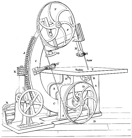
Fig. 3139.
Fig. 3139 represents Worssam’s band saw machine, in which the standard may be set at any required angle for cutting bevels.
When the work is heavy and not easily handled it is preferable to set the standard and saw at the required angle, rather than to set the table at an angle and have the saw remain vertical. In Worssam’s machine this is accomplished as follows:
a is the main frame carrying the work table t, and having circular guideways b, b′, which carry the standard c having guide c′ for working in the circular guideways b, b′.
The saw-driving wheel d, is carried in bearings provided in c, and, therefore moves when the standard c is moved.
At the upper end of c, is the slide e, which carries the bearing for the upper wheel f, this slide being adjusted to regulate the saw tension by the hand wheel o, whose screw threads into a nut in the slide e. h carries the front guide g, for the saw, the back guide g′ being carried by a bracket bolted to c. The back guide is fixed in position, but the front one is adjustable to suit the height of the work by raising or lowering it.
The means for setting the saw at the required angle to the work table are as follows:
At the back of the standard c is a rack j, whose pitch line is an arc of a circle of which the axis of the guideway c′ is the centre.
Into the rack j fits the worm wheel k, at the bottom of the shaft of which is a pair of bevel gear wheels l, which are operated by the hand wheel m.
VOL. II. BAND SAW MILL. PLATE XXIII.
Large image (130 kB).
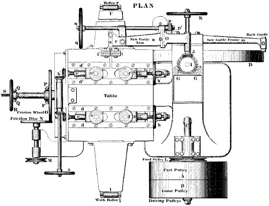
Fig. 3140.
Large image (109 kB).
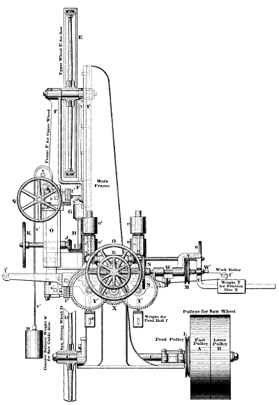
Fig. 3141.
Large image (130 kB).
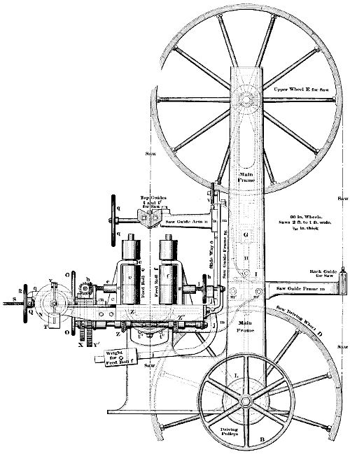
Fig. 3142.
A band saw machine constructed by Messrs. London, Berry & Orton, is shown by Figs. 3140, 3141 and 3142, in plate XXIII. The saw-driving wheel d, has wrought iron arms turned true and screwed into the wheel hub. The wooden segments have their grain lengthways of the rim, and between them are placed pieces of soft wood with the grain across the rim. This acts to keep the joints tight, notwithstanding the expansion and contraction of the wood.
The upper wheel is adjusted for straining the saw, and for leading the saw true, by the following construction. It is carried in a U-shaped frame f, which is pivoted at y to a slide that is gibbed to the main frame, and by operating the screw shown at x, the frame f is set to the required level.
To regulate the tension of the saw, the hand wheel k is operated, which drives the pair of bevel gears j and i, the latter of which operates the threaded shaft h, whose upper end g connects with the slide which carries f. Within g is a spring to act as a cushion to the slide, and thus prevent saw breakage should a chip pass between the saw and its driving wheel.
The saw guide frame is secured to the main frame at m′, m′. Upon the face of m, is a slideway for the saw guide arm n, which may thus be adjusted as closely to the upper face of the work as possible.
The weight of arm n is counterbalanced by a rope passing over the pulley v, and supporting the counterbalance weight w. The feed motion is constructed as follows:
On the same shaft as the main fast and loose pulleys a, b, is the feed pulley l, which by belt connection drives pulley m, which is on the shaft w, upon which is a friction disc n, by means of which the rate of feed is regulated. The feed disc n drives the wheel o; the degree of contact between these two (n and o) is regulated by means of the weight t, on the lever u.
On the same shaft as the friction wheel o, is a pinion driving the gear x, which is on the same shaft as the pinion y, which drives the two gears y′ and y′′.
Referring now to Fig. 3142, gear y′ drives the pair of bevel gears z and z′, for the feed roll e, and the pair of bevel gears shown at z′′, the feed roll f. The gear y′′ drives similar gearing for the feed rolls e′ and f′, seen in the plan Fig. 3140.
Referring now to the plan Fig. 3140, and the side elevation, Fig. 3142, the feed roll f is carried in a frame g, which is fitted on the slideway d, d, and receives a screw i, upon which is a hand wheel h; at the back of this wheel is the lever j, which is weighted as shown, so that the force with which feed roll f grips the work is determined by the weighted lever j, and may be varied to suit the nature of the work by moving the weight along j.
The construction of the gear for feed roll f′ is similar, as may be seen in the plan Fig. 3140, f′ being in a slide g′, which has a screw i′, and hand wheel h′, a weighted lever corresponding to j acting against wheel h′. In proportion as f and f′ are opened out to admit thick stuff or work, the hand wheels h and h′, respectively are used to screw the screws i and i′ into their respective slides g and g′, and thus maintain the weighted levers in their requisite horizontal positions. The feed rolls e and e′ are carried in slides c and c′, and are adjusted to suit the thickness of the stuff or work by a hand gearing, which consists of the hand wheel a, seen in the plan and in the front elevation, Fig. 3141, which drives the pinions b and b′, which operate screws for the slides c and c′, the latter being a left hand screw. The front rolls e and e′ are therefore held in a fixed position, whereas the back ones f and f′ may open out under the pressure of the weighted levers j, and thus accommodate any variation in the thickness of the work.
The rate of feed is varied to suit the nature of the work by the following construction: The friction wheel o and the hand wheel r are connected by a yoke q, Fig. 3142, at the ends of which are the joints p, q, seen in the plan, Fig. 3140. Hand wheel r is threaded to receive the screw s, and it follows that by revolving r, the friction wheel o may be moved towards the centre of the friction disc n, which would reduce the velocity with which n would drive o, and therefore reduce the rate of feed. If the friction wheel o be moved from the position it occupies in the plan Fig. 3140, to any point on the other side of the centre of the friction disc n, the direction of feed motion would be reversed.
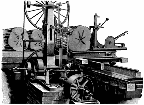
Fig. 3143.
A band saw machine for the conversion of logs into timber, and constructed by Messrs. London, Berry & Orton, is shown in Fig. 3143. The logs are fixed to the carriage by dogs and the carriage traverses the log to the feed.
VOL. II. LOG CROSS‑CUTTING MACHINE. PLATE XXIV.
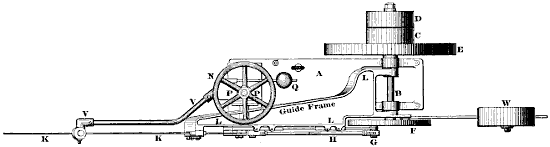
Fig. 3144.
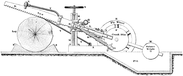
Fig. 3145.
Reciprocating Cross Cutting Saw For Logs.—The machine shown in Figs. 3144 and 3145 is designed for the purpose of cutting heavy and long logs into convenient lengths preparatory to cutting the logs up in other machines, and it is usually therefore placed at the entrance to the mill, where it is of immediate service as the lumber comes into the building.
The machine here shown is intended for logs up to 36 inches in diameter, is simple in construction, requires very little foundation, is easy to handle, and occupies but very little room.
The saw is here fed mechanically to its cut, whereas in some machines it is fed by its own weight, and therefore requires great care to be taken, when the saw is finishing its cut, in order to prevent it from falling after it has passed through the log.
Fig. 3145 is a side elevation and Fig. 3144 a plan of the machine, in which a is the frame of the machine on which are the bearings for the shaft b carrying the fast pulley c, loose pulley d and fly-wheel e at one end, and at the other, a crank disc f, whose pin is shown at g. This drives the saw k through the medium of the connecting rod h.
The saw is fast at the butt end to along slide j, j, which works in a long guide formed on the face of the swinging frame l, which pivots at one end on the shaft b and at the other is carried by a slide p, on the vertical slideway m, and is fed down the same to give the saw its cut by the screw whose hand wheel is shown at n.
v is a second guide for the saw, and being connected to the slide feeds down with the saw until it meets the log.
A counterweight w balances the weight of the slides and saw, so that there being a pit beneath the balance weight the saw and its guides may be raised so that the saw stands out of the way when not in use. y is a dog for holding the log, which is also blocked by the wedges z z′.
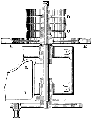
Fig. 3146.
The construction of the main bearing is shown in Fig. 3146, in which it is seen that the hub or boss of the loose pulley is much longer than that of the fast one, thus providing a large amount of bearing surface, which is advantageous because the belt will remain longer at the loose pulley than it will on the tight one. The sleeves or bushes in which the shaft runs afford a simple means of renewal to restore the fit when the shaft has worn loose in its bearings.
It is obvious that as the guide frame l is pivoted to the shaft b, it carries the end of the saw (as it is fed down) in an arc of a circle of which the axis of b is the centre, whereas the slideway m is straight, and slide p therefore moves in a straight line instead of in the required arc. Provision however is made to accommodate these two motions as follows:
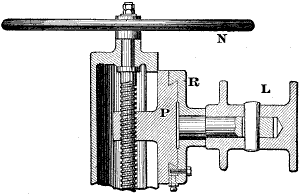
Fig. 3147.
Fig. 3147 is a sectional view of the slides on the slideway m and Fig. 3148 a plan of the same. The hand wheel n corresponds to n in Fig. 3145. Upon the vertical slideway (in Fig. 3145) of the standard fits the slide p, which has a horizontal slideway for the slide r, which is free to slide automatically, having no screw or other device to restrain it, save the guide frame l, and therefore as this frame is lowered to feed the saw the slide r moves automatically to accommodate the arc of a circle in which the guide moves on account of being pivoted at b.
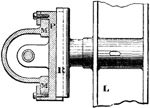
Fig. 3148.
Horizontal Saw Frame.—This machine is designed for the more expensive woods, such as mahogany, and is finding much favor because it will cut at a very high speed, the saw travelling about 150 feet per minute.
The roughest shaped trunk may be easily fixed on the travelling table, and a thin saw may be used as it may be very tightly strained. This machine is used either for breaking down timber, or for converting it from the log to any desired thickness, the thickness of the boards being very readily and easily varied.
The machine consists essentially of a framework carrying either one or two very thin and tightly strained saws operating horizontally and cutting on both strokes, so that the feed is continuous, the construction being as follows:
VOL. II. HORIZONTAL SAW FRAME. PLATE XXV.
Large image (108 kB).
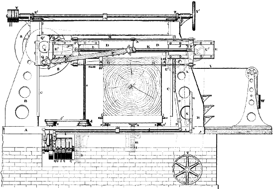
Fig. 3149.
Referring to Figs. 3149 and 3150, a is a base plate or bed carrying two uprights or standards b, b, having guideways c, c, for the cross-head d, which has slideways e, e′, for carrying the frame f, f, which carries the saw g, which is guided on each side of the work by the guides h, h′.
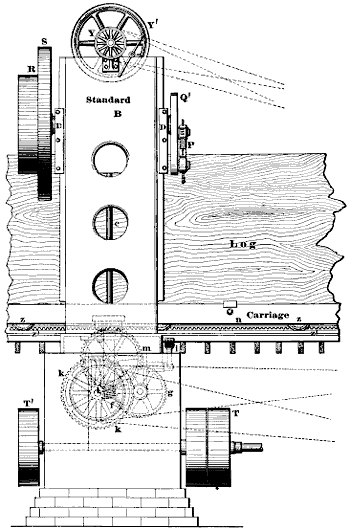
Fig. 3150.
The frame f, f is connected to the slides j, j′, and has the rod k, to which the connecting rod pin l is attached, and the rod m, which acts as a stretcher. A connecting rod p, connects the pin l to the crank pin q, on the crank q′, which is driven by belt from the pulley t, a fly-wheel being provided at s.
It is obvious that as the crank revolves the saw reciprocates, its line of motion being determined by the guideways e, e′.

Fig. 3151.
The construction of the saw is shown in Fig. 3151, and it is seen that for half its length, the teeth are formed to cut when the saw moves in one direction, while for the other half the teeth slope in the opposite direction, and are therefore arranged to cut when the saw is on the opposite or return stroke, and the construction whereby the saw is enabled to cut on both strokes is obtained as follows:
Referring to Fig. 3149, the two slides e, e′, on which the saw-carrying frame f f slides, are not in line or parallel one with the other, but each slide is at an angle of about 85 degrees to the line of feed, so that as frame f is reciprocated at each stroke, one end of the saw advances towards the cut, and the other recedes from it, thus causing the saw to cut first on one half and then on the other of its length, one half cutting on the forward, and the other on the return stroke.
The studs or saw-buckles for attaching the saw to the frame are shown in Fig. 3151, in place on the ends of the saw, the part i, that fits in the frame f, Fig. 3149, being squared so that the saw cannot be twisted in tightening up the nuts of the saw-buckle.
The belt works for driving the saw are arranged as follows: at t are the fast and loose pulleys for driving pulley r, the belt passing from t over two pulleys (shown dotted in, Fig. 3149), u, u′, whence it stretches to the crank driving pulley r, whose bearing is provided on the cross-head, so that the two move together when the cross-head is altered in height from the work-table or carriage, to accommodate different thicknesses or diameters of logs.
It is obvious that in proportion as the cross-head is set nearer to the carriage, the belt from t to u, u′ would become slack; provision is made however, to prevent this as follows:
Pulley u, is carried on a frame or swing lever x, to which is attached by rope v the weight w, which therefore regulates the tension of the belt.
The cross-head d may be raised or lowered by belt power or by hand, as occasion may require, the usual course being to move it to nearly the required position by belt power, and then complete the adjustment by hand, a graduated scale being provided as shown, whereby the rack can be set to cut the required thickness of plank without measuring the timber.
The belt motion for raising or lowering the cross-head is obtained by the pulleys at y, the wheel for the hand adjustment being shown at y′. In either case the bevel gear wheels z, z′ operate, respectively, a vertical screw engaging a nut on the cross-head.
The log feed is obtained by a motion separate from the return motion, there being three rates of feed and a quick return motion, the construction being as follows:
Referring to Figs. 3149 and 3150, a is a belt pulley fast on the crank shaft, and driving pulley b, which is also shown dotted in. Pulley b drives the vertical shaft c, on which is the cone pulley d, having three steps, and which drives (by means of belt d′) cone pulley e, on which is a worm f, driving the worm wheel g, which runs idle on its shaft unless engaged therewith by means of the clutch h. The shaft of worm wheel g is omitted in Fig. 3149, so as to leave the belt-shifting mechanism for pulleys q, q′ exposed to view. On this shaft however is a pinion driving the gear wheel k, on whose shaft is a pinion l, driving the gear m, which engages the rack n, on the under side of the carriage.
The clutch h is engaged by the lever i, to the upper arm of which is attached the rod j, j, from the lever p, hence operating p (which is done by hand), back and forth, throws clutch h into and out of gear with the worm wheel g, and puts the carriage feed on or throws it out, according to the direction in which p is moved.
The upper end of shaft c is carried in a bearing on the cross-head, and is provided with a featherway or spline, so that as the cross-head is raised or lowered the upper end of c passes through its upper bearing, and the pulley b travels with the cross-head. The three rates of carriage feed are obviously obtained by means of the three steps on the cone pulleys d and e.
We have now to explain the construction of the mechanism for traversing the table back, and giving it a quick return motion, or in other words a quicker motion on the back than on the feed traverse, and this is arranged as follows: