Volume 1 — Chapter III.—THE TEETH OF GEAR-WHEELS (continued). (continued 2)
Reading edition
For a pair of wheels Mr. Walker strikes the face curve by a point on the pitch rolling circle, and the flanks by a point on the addendum circle, fastening a piece of wood to the pitch circle to carry the tracing point. The flank of each wheel is struck with a tracing point, thus attached to the pitch circle of the other wheel.
The proportions of teeth and of the spaces between them are usually given in turns of the pitch, so that all teeth of a given pitch shall have an equal thickness, height, and breadth, with an equal addendum and flank, and the same amount of clearance.
The term “clearance” as applied to gear-wheel teeth means the amount of space left between the teeth of one wheel, and the spaces in the other, or, in other words, the difference between the width of the teeth and that of the spaces between the teeth.
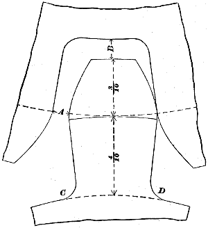
Fig. 143.
This clearance exists at the sides of the teeth, as in Fig. 143, at a, and between the tops of the teeth and the bottoms or roots of the spaces as at b. When, however, the simple term clearance is employed it implies the side clearance as at a, the clearance at b being usually designated as top and bottom clearance. Clearance is necessary for two purposes; first, in teeth cut in a machine to accurate form and dimensions, to prevent the teeth of one wheel from binding in the spaces of the other, and second, in cast teeth, to allow for the imperfections in the teeth which are incidental to casting in a founder’s mould. In machine-cut teeth the amount of clearance is a minimum.
In wheels which are cast with their teeth complete and on the pattern, the amount of clearance must be a maximum, because, in the first place, the teeth on the pattern must be made taper to enable the extraction of the pattern from the mould without damage to the teeth in the mould, and the amount of this taper must be greater than in machine-moulded teeth, because the pattern cannot be lifted so truly vertical by hand as to avoid, in all cases, damage to the mould; in which case the moulder repairs the mould either with his moulding tools and by the aid of the eye, or else with a tooth and a space made on a piece of wood for the purpose. But even in this case the concentricity of the teeth is scarcely likely to be preserved.
It is obvious that by reason of this taper each wheel is larger in diameter on one side than on the other, hence to preserve the true curves to the teeth the pitch circle is made correspondingly smaller. But if in keying the wheels to their shafts the two large diameters of a pair of wheels be placed to work together, the teeth of the pair would have contact on that side of the wheel only, and to avoid this and give the teeth contact across their full breadth the wheels are so placed on their shafts that the large diameter of one shall work with the small one of the other, the amount of taper being the same in each wheel irrespective of their relative diameters. This also serves to keep the clearance equal in amount both top, and bottom, and sideways.
A second imperfection is that in order to loosen the pattern in the sand or mould, and enable its extraction by hand from the mould, the pattern requires to be rapped in the mould, the blows forcing back the sand of the mould and thus loosening the pattern. In ordinary practice the amount of this rapping is left entirely to the judgment of the moulder, who has nothing to guide him in securing an equal amount of pattern movement in each direction in the mould; hence, the finished mould may be of increased radius at the circumference in the direction in which the wheel moved most during the rapping. Again, the wood pattern is apt in time to shrink and become out of round, while even iron patterns are not entirely free from warping. Again, the cast metal is liable to contract in cooling more in one direction than in another. The amount of clearance usually allowed for pattern-moulded cast gearing is given by Professor Willis as follows:—Whole depth of tooth 7⁄10, of the pitch working depth 6⁄10; hence 1⁄10 of the pitch is allowed for top and bottom clearance, and this is the amount shown at b in Fig. 143. The amount of side clearance given by Willis as that ordinarily found in practice is as follows:—“Thickness of tooth 5⁄11 of the pitch; breadth of space 6⁄11; hence, the side clearance equals 1⁄11 of the pitch, which in a 3-inch pitch equals .27 of an inch in each wheel.” Calling this in round figures, which is near enough for our purpose, 1⁄4 inch, we have thickness of tooth 11⁄4, width of space 13⁄4, or 1⁄2 inch of clearance in a 3-inch pitch, an amount which on wheels of coarse pitch is evidently more than that necessary in view of the accuracy of modern moulding, however suitable it may have been for the less perfect practice of Professor Willis’s time. It is to be observed that the rapping of the pattern in the founder’s mould reduces the thickness of the teeth and increases the width of the spaces somewhat, and to that extent augments the amount of side clearance allowed on the pattern, and the amount of clearance thus obtained would be nearly sufficient for a small wheel, as say of 2 inches diameter. It is further to be observed that the amount of rapping is not proportionate to the diameter of the wheel; thus, in a wheel of 2 inches diameter, the rapping would increase the size of the mould about 1⁄32 inch. But in the proportion of 1⁄32 inch to every 2 inches of diameter, the rapping on a 6-foot wheel would amount to 11⁄16 inches, whereas, in actual practice, a 6-foot wheel would not enlarge the mould more than at most 1⁄8 inch from the rapping.
It is obvious, then, that it would be more in accordance with the requirements to proportion the amount of clearance to the diameter of the wheel, so as to keep the clearance as small as possible. This will possess the advantage that the teeth will be stronger, it being obvious that the teeth are weakened both from the loss of thickness and the increase of height due to the clearance.
It is usual in epicycloidal teeth to fill in the corner at the root of the tooth with a fillet, as at c, d, in Fig. 143, to strengthen it. This is not requisite when the diameter of the generating circle is so small in proportion to the base circle as to produce teeth that are spread at the roots; but it is especially advantageous when the teeth have radial flanks, in which case the fillets may extend farther up the flanks than when they are spread; because, as shown in Fig. 47, the length of operative flank is a minimum in teeth having radial flanks, and as the smallest pinion in the set is that with radial flanks, and further as it has the least number of teeth in contact, it is the weakest, and requires all the strengthening that the fillets in the corners will give, and sometimes the addition of the flanges on the sides of the pinion, such gears being termed “shrouded.”
The proportion of the teeth to the pitch as found in ordinary practice is given by Professor Willis as follows:—
Depth to pitch line 3⁄10 of the pitch.
Working depth 6⁄10 „ „
Whole depth 7⁄10 „ „
Thickness of tooth 5⁄11 „ „
Breadth of space 6⁄11 „ „
The depth to pitch line is, of course, the same thing as the height of the addendum, and is measured through the centre of the tooth from the point to the pitch line in the direction of a radial line and not following the curve of tooth face.
Referring to the working depth, it was shown in Figs. 42 and 44 that the height of the addendum remaining constant, it varies with the diameter of the generating circle.
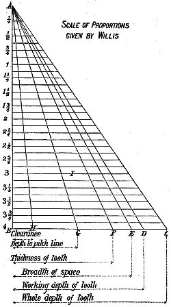
Fig. 144.
From these proportions or such others as may be selected, in which the proportions bear a fixed relation to the pitch, a scale may be made and used as a gauge, to set the compasses by, and in marking off the teeth for any pitch within the capacity of the scale. A vertical line a b in Fig. 144, is drawn and marked off in inches and parts of an inch, to represent the pitches of the teeth; at a right angle to a b, the line b c is drawn, its length equalling the whole depth of tooth, which since the coarsest pitch in the scale is 4 inches will be 7⁄10 of 4 inches. From the end of line c we draw a diagonal line to a, and this gives us the whole depth of tooth for any pitch up to 4 inches: thus the whole depth for a 4-inch pitch is the full length of the horizontal line b c; the whole depth for a 3-inch pitch will be the length of the horizontal line running from the 3 on line a b, to line a c on the right hand of the figure; similarly for the full depth of tooth for a 2-inch pitch is the length of the horizontal line running from 2 to a c. The working depth of tooth being 6⁄10 of the pitch a diagonal is drawn from a meeting line c at a distance from b of 6⁄10 of 4 inches and we get the working depth for any other pitch by measuring (along the horizontal line corresponding to that pitch), from the line of pitches to the diagonal line for working depth of tooth. The thickness of tooth is 5⁄11 of the pitch and its diagonal is distant 5⁄11 of 4 (from b) on line b c, the thickness for other pitches being obtained on the horizontal line corresponding to those pitches as before.
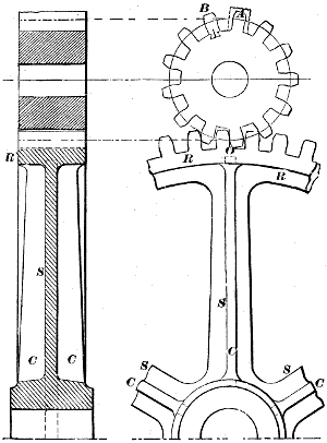
Fig. 145.
The construction of a pattern wherefrom to make a foundry mould, in which to cast a spur gear-wheel, is as shown in section, and in plan of Fig. 145. The method of constructing these patterns depends somewhat on their size. Large patterns are constructed with the teeth separate, and the body of the wheel is built of separate pieces, forming the arms, the hub, the rim, and the teeth respectively. Pinion patterns, of six inches and less in diameter, are usually made out of a solid piece, in which case the grain of the wood must lie in the direction of the teeth height. The chuck or face plate of the lathe, for turning the piece, must be of smaller diameter than the pinion, so that it will permit access to a tool applied on both sides, so as to strike the pitch circle on both sides. A second circle is also struck for the roots or depths of the teeth, and also, if required, an extra circle for striking the curves of the teeth with compasses, as was described in Fig. 130. All these circles are to be struck on both sides of the pattern, and as the pattern is to be left slightly taper, to permit of its leaving the mould easily, they must be made of smaller diameter on one side than on the other of the pattern; the reduction in diameter all being made on the same side of the pattern. The pinion body must then be divided off on the pitch line into as many equal divisions as there are to be teeth in it; the curves of the teeth are then marked by some one of the methods described in the remarks on curves of gear-teeth. The top of the face curves are then marked along the points of the teeth by means of a square and scribe, and from these lines the curves are marked in on the other side of the pinion, and the spaces cut out, leaving the teeth projecting. For a larger pinion, without arms, the hub or body is built up of courses of quadrants, the joints of the second course breaking joint with those of the first.
The quadrants are glued together, and when the whole is formed and the glue dry, it is turned in the lathe to the diameter of the wheel at the roots of the teeth. Blocks of wood, to form the teeth, are then planed up, one face being a hollow curve to fit the circle of the wheel. The circumference of the wheel is divided, or pitched off, as it is termed, into as many points of equal division as there are to be teeth, and at these points lines are drawn, using a square, having its back held firmly against the radial face of the pinion, while the blade is brought coincidal with the point of division, so as to act as a guide in converting that point into a line running exactly true with the pinion. All the points of division being thus carried into lines, the blocks for the teeth are glued to the body of the pinion, as denoted by a, in Fig. 145. Another method is to dovetail the teeth into the pinion, as in Fig. 145 at b. After the teeth blocks are set, the process is, as already described, for a solid pinion.
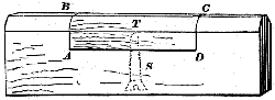
Fig. 146.
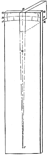
Fig. 147.
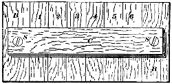
Fig. 148.
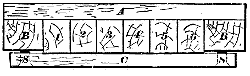
Fig. 149.
The construction of a wheel, such as shown in Fig. 145, is as follows: The rim r must be built up in segments, but when the courses of segments are high enough to reach the flat sides of the arms they should be turned in the lathe to the diameter on the inside, and the arms should be let in, as shown in the figure at o. The rest of the courses of segments should then be added. The arms are then put in, and the inside of the segments last added may then be turned up, and the outside of the rim turned. The hub should then be added, one-half on each side of the arms, as in the figure. The ribs c of the arms are then added, and the body is completed (ready to receive the teeth), by filleting in the corners. An excellent method of getting out the teeth is as follows: Shape a piece of hard wood, as in Fig. 146, making it some five or six inches longer than the teeth, and about three inches deeper, the thickness being not less than the thickness of the required teeth at the pitch line. Parallel to the edge b c, mark the line a d, distant from b c to an amount equal to the required depth of tooth. Mark off, about midway of the piece, the lines a b and c d, distant from each other to an amount equal to the breadth of the wheel rim, and make two saw cuts to those lines. Take a piece of board an inch or two longer than the radius of the gear-wheel and insert a piece of wood (which is termed a box) tightly into the board, as shown in Fig. 147, e representing the box. Let the point f on the board represent the centre of the wheel, and draw a radial line r from f through the centre of the box. From the centre f, with a trammel, mark the addendum line g g, pitch line h i, and line j k for the depth of the teeth (and also a line wherefrom to strike the teeth curves, as shown in Fig. 129 if necessary). From the radial line r, as a centre, mark off on the pitch circle, points of division for several teeth, so as to be able to test the accuracy of the spacing across the several points, as well as from one point to the next, and mark the curves for the teeth on the end of the box, as shown. Turn the box end for end in the board, and mark out a tooth by the same method on the other end of the box. The box being removed from the board must now have its sides planed to the lines, when it will be ready to shape the teeth in. The teeth are got out for length, breadth, and thickness at the pitch line as follows: The lumber from which they are cut should be very straight grained, and should be first cut into strips of a width and thickness slightly greater than that of the teeth at the pitch line. These strips (which should be about two feet long) should then be planed down on the sides to very nearly the thickness of the tooth at the pitch line, and hollow on one edge to fit the curvature of the wheel rim. From these strips, pieces a trifle longer than the breadth of the wheel rim are cut, these forming the teeth. The pieces are then planed on the ends to the exact width of the wheel rim. To facilitate this planing a number of the pieces or blank teeth may be set in a frame, as in Figs. 148 and 149, in which a is a piece having the blocks b b affixed to it. c is a clamp secured by the screws at s s, and 1, 2, 3, 4, 5, 6 are the ends of the blank teeth. The clamp need not be as wide as the teeth, as in Fig. 148, but it is well to let the pieces a and b b equal the breadth of the wheel rim, so that they will act as a template to plane the blank teeth ends to. The ends of b b may be blackleaded, so as to show plainly if the plane blade happens to shave them, and hence to prevent planing b b with the teeth. The blank teeth may now be separately placed in the box (Fig. 146) and secured by a screw, as shown in that figure, in which s is the screw, and t the blank tooth. The sides of the tooth must be carefully planed down equal and level with the surface of the box. The rim of the wheel, having been divided off into as many divisions as there are to be teeth in the wheel, as shown in Fig. 150, at a, a, a, &c., the finished teeth are glued so that the same respective side of each tooth exactly meets one of the lines a. Only a few spots of glue should be applied, and these at the middle of the root thickness, so that the glue shall not exude and hide the line a, which would make it difficult to set the teeth true to the line. When the teeth are all dry they must be additionally secured to the rim by nails. Wheels sufficiently large to incur difficulty of transportation are composed of a number of sections, each usually consisting of an arm, with an equal length of the rim arc on each side of it, so that the joint where the rim segments are bolted together will be midway between the two arms.
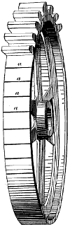
Fig. 150.
This, however, is not absolutely necessary so long as the joints are so arranged as to occur in the middle of tooth spaces, and not in the thickness of the tooth. This sometimes necessitates that the rim sections have an unequal length of arc, in which event the pattern is made for the longest segment, and when these are cast the teeth superfluous for the shorter segments are stopped off by the foundry moulder. This saves cutting or altering the pattern, which, therefore, remains good for other wheels when required.
When the teeth of wheels are to be cut in a gear-cutting machine the accurate spacing of the teeth is determined by the index plate and gearing of the machine itself; but when the teeth are to be cast upon the wheel and a pattern is to be made, wherefrom to cast the wheel the points of division denoting the thickness of the teeth and the width of the spaces are usually marked by hand. This is often rendered necessary from the wheels being of too large a diameter to go into dividing machines of the sizes usually constructed.
To accurately divide off the pitch circle of a gear-wheel by hand, requires both patience and skilful manipulation, but it is time and trouble that well repays its cost, for in the accuracy of spaces lies the first requisite of a good gear-wheel.
It is a very difficult matter to set the compasses so that by commencing at any one point and stepping the compasses around the circle continuously in one direction, the compass point shall fall into the precise point from which it started, for if the compass point be set the 1⁄200th inch out, the last space will come an inch out in a circle having 200 points of divisions. It is, therefore, almost impossible and quite impracticable to accurately mark or divide off a circle having many points of division in this manner, not only on account of the fineness of the adjustment of the compass points, but because the frequent trials will leave so many marks upon the circle that the true ones will not be distinguishable from the false. Furthermore, the compass points are apt to spring and fall into the false marks when those marks come close to the true ones.
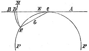
Fig. 151.
In Fig. 151 is shown a construction by means of which the compass points may be set more nearly than by dividing the circumference of the circle by the number of divisions it is required to be marked into and setting the compasses to the quotient, because such a calculation gives the length of the division measured around the arc of the circle, instead of the distance measured straight from point of division to point of division.
The construction of Fig. 151 is as follows: p p is a portion of the circle to be divided, and a b is a line at a tangent to the point c of the circle p p. The point d is set off distant from c, to an amount obtained by dividing the circumference of p p by the number of divisions it is to have. Take one-quarter of this distance c d, and mark it from c, giving the point e, set one point of the compass at e and the other at d, and draw the arc d f, and the distance from f to c, as denoted by g, is the distance to which to set the compasses to divide the circle properly. The compasses being set to this distance g, we may rest one compass point at c, and mark the arc f h, and the distance between arc h and arc d, measured on the line a b, is the difference between the points c, f when measured around the circle p p, and straight across, as at g.
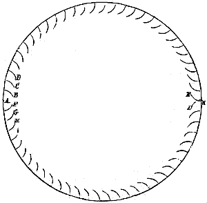
Fig. 152.
A pair of compasses set even by this construction will not, however, be entirely accurate, because there will be some degree of error, even though it be in placing the compass points on the lines and on the points marked, hence it is necessary to step the compasses around the circle, and the best method of doing this is as follows: Commencing at a, Fig. 152, we mark off continuously one from the other, and taking care to be very exact to place the compass point exactly coincident with the line of the circle, the points b, c, d, &c., continuing until we have marked half as many divisions as the circle is to contain, and arriving at e, starting again at a, we mark off similar divisions (one half of the total number), f, g, h, arriving at i, and the centre k, between the two lines e, i, will be the true position of the point diametrally opposite to point a, whence we started. These points are all marked inside the circle to keep them distinct from those subsequently marked.
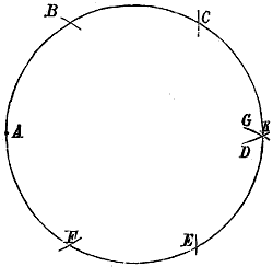
Fig. 153.
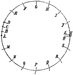
Fig. 154.
It will be, perhaps, observed by the reader that it would be more expeditious, and perhaps cause less variation, were we to set the compasses to the radius of the circle and mark off the point k, as shown in Fig. 153, commencing at the point a, and marking off on the one side the lines b, c, and d, and on the other side e, f, and g, the junction or centre, between g and d, at the circle being the true position of the point k. For circles struck upon flat surfaces, this plan may be advantageous; and in cases where there are not at hand compasses large enough, a pair of trammels may be used for the purpose; but our instructions are intended to apply also to marking off equidistant points on such circumferences as the faces of pulleys or on the outsides of small rings or cylinders, in which cases the use of compasses is impracticable. The experienced hand may, it is true, adjust the compasses as instructed, and mark off three or four of the marks b, c, &c., in Fig. 152, and then open out the compasses to the distance between the two extreme marks, and proceed as before to find the centre k, but as a rule, the time saved will scarcely repay the trouble; and all that can be done to save time in such cases is, if the holes come reasonably close together, to mark off, after the compasses are adjusted, three or four spaces, as shown in Fig. 154. Commencing at the point a, and marking off the points b, c, and d, we then set another pair of compasses to the distance between a and d, and then mark, from d on one side and from a on the other, the marks from f to l and from m to t, thus obtaining the point k. This method, however expeditious and correct for certain work, is not applicable to circumferential work of small diameter and in which the distance between two of the adjacent points is, at the most, 1⁄20 of the circumference of the circle; because the angle of the surface of the metal to the compass point causes the latter to spring wider open in consequence of the pressure necessary to cause the compass point to mark the metal. This will be readily perceived on reference to Fig. 155 in which a represents the stationary, and b the scribing or marking point of the compasses.
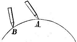
Fig. 155.
The error in the set of the compasses as shown by the distance apart of the two marks e and i on the circle in Fig. 152 is too fine to render it practicable to remedy it by moving the compass legs, hence we effect the adjustment by oilstoning the points on the outside, throwing them closer together as the figure shows is necessary.
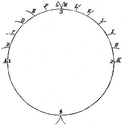
Fig. 156.
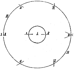
Fig. 157.
Having found the point k, we mark (on the outside of the circle, so as to keep the marks distinct from those first marked) the division b, c, d, Fig. 156, &c., up to g, the number of divisions between b and g being one quarter of those in the whole circle. Then, beginning at k, we mark off also one quarter of the number of divisions arriving at m in the figure and producing the point 3. By a similar operation on the other side of the circle, we get the true position of point No. 4. If, in obtaining points 3 and 4, the compasses are not found to be set dead true, the necessary adjustment must be made; and it will be seen that, so far, we have obtained four true positions, and the process of obtaining each of them has served as a justification of the distance of the compass points. From these four points we may proceed in like manner to mark off the holes or points between them; and the whole will be as true as it is practicable to mark them off upon that size of circle. In cases, however, where mathematical precision is required upon flat and not circumferential surfaces, the marking off may be performed upon a circle of larger diameter, as shown in Fig. 157. If it is required to mark off the circle a, Fig. 157, into any even number of equidistant points, and if, in consequence of the closeness together of the points, it becomes difficult to mark them (as described) with the compasses, we mark a circle b b of larger diameter, and perform our marking upon it, carrying the marks across the smaller circle with a straightedge placed to intersect the centres of the circles and the points marked on each side of the diameter. Thus, in Fig. 157, the lines 1 and 2 on the smaller circle would be obtained from a line struck through 1 and 4 on the outer circle; and supposing the larger circle to be three times the size of the smaller, the deviation from truth in the latter will be only 1⁄3 of whatever it is in the former.
In this example we have supposed the number of divisions to be an even one, hence the point k, Fig. 152, falls diametrically opposite to a, whereas in an odd number of points of division this would not be the case, and we must proceed by either of the two following methods:—
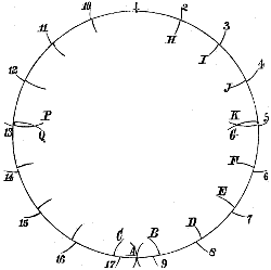
Fig. 158.
In Fig. 158 is shown a circle requiring to be divided by 17 equidistant points. Starting from point 1 we mark on the outside of the circumference points 2, 3, 4, &c., up to point 9. Starting again from point 1 we mark points 10, 11, &c., up to 17. If, then, we try the compasses to 17 and 9 we shall find they come too close together, hence we take another pair of compasses (so as not to disturb the set of our first pair) and find the centre between 9 and 17 as shown by the point a. We then correct the set of our first pair of compasses, as near as the judgment dictates, and from point a, we mark with the second compasses (set to one half the new space of the first compasses) the points b, c. With the first pair of compasses, starting from b, we mark d, e, &c., to g; and from i, we mark divisions h, i, &c., to k, and if the compasses were set true, k and g would meet at the circle. We may, however, mark a point midway between k and g, as at 5. Starting again from points c and i, we mark the other side of the circle in a similar manner, producing the lines p and q, midway between which (the compasses not being set quite correct as yet) is the true point for another division. After again correcting the compasses, we start from b and 5 respectively, and mark point 7, again correcting the compasses. Then from c and the point between p and q, we may mark an intermediate point, and so on until all the points of division are made. This method is correct enough for most practical purposes, but the method shown in Fig. 159 is more correct for an odd number of points of division. Suppose that we have commenced at the point marked i, we mark off half the required number of holes on one side and arrive at the point 2; and then, commencing at the point i again, we mark off the other half of the required number of holes, arriving at the point 3. We then apply our compasses to the distance between the points 2 and 3; and if that distance is not exactly the same to which the compasses are set, we make the necessary adjustment, and try again and again until correct adjustment is secured.
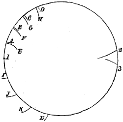
Fig. 159.
It is highly necessary, in this case, to make the lines drawn at each trial all on the same side of the circle and of equal length, but of a different length to those marked on previous trials. For example, left the lines a, b, c, d, in Fig. 159 represent those made on the first trial, and e, f, g, h, those made on the second trial; and when the adjustment is complete, let the last trial be made upon the outside or other side of the circle, as shown by the lines i, j, k, l. Having obtained the three true points, marked 1, 2, 3, we proceed to mark the intermediate divisions, as described for an even number of divisions, save that there will be a space, 2 and 3, opposite point 1, instead of a point, as in case of a circle having an even number of divisions.
The equal points of division thus obtained may be taken for the centres of the tooth at the pitch circle or for one side of the teeth, as the method to be pursued to mark the tooth curves may render most desirable. If, for example, a template be used to mark off the tooth curves, the marks may be used to best advantage as representing the side of a tooth, and from them the thickness of the tooth may be marked or not as the kind of template used may require. Thus, if the template shown in Fig. 21 be used, no other marks will be used, because the sides of a tooth on each side of a space may be marked at one setting of the template to the lines or marks of division. If, however, a template, such as shown in Fig. 81 be used, a second set of lines marked distant from the first to a radius equal to the thickness of a tooth becomes necessary so that the template may be set to each line marked. If the Willis odontograph or the Robinson template odontograph be used the second set of lines will also be necessary. In using the Walker scale a radial line, as g in Fig. 142, will require to be marked through the points of equal division, and the thickness of the tooth at the points on the pitch circle and at the root must be marked as was shown in Fig. 142.
But if the arcs for the tooth curves are to be marked by compasses, the location for the centres wherefrom to strike these arcs may be marked from the points of division as was shown in Fig. 130.
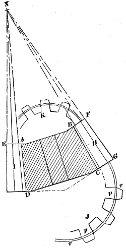
Fig. 160.
To construct a pattern wherefrom to cast a bevel gear-wheel.—When a pair of bevel-wheels are in gear and upon their respective shafts all the teeth on each wheel incline, as has been shown, to a single point, hence the pattern maker draws upon a piece of board a sketch representing the conditions under which the wheels are to operate. A sketch of this kind is shown in Fig. 160, in which a, b, c, d, represent in section the body of a bevel pinion. f g is the point of a tooth on one side, and e the point of a tooth on the other side of the pinion, while h i are pitch lines for the two teeth. Thus, the cone surface, the points, the pitch lines and the bottom of the spaces, projected as denoted by the dotted lines, would all meet at x, which represents the point where the axes of the shafts would meet.
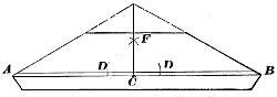
Fig. 161.
In making wooden patterns wherefrom to cast the wheels, it is usual, therefore, to mark these lines on a drawing-board, so that they may be referred to by the workman in obtaining the degree of cone necessary for the body a b c d, to which the teeth are to be affixed. Suppose, then, that the diameter of the pinion is sufficiently small to permit the body a b c d to be formed of one piece instead of being put together in segments, the operation is as follows: The face d c is turned off on the lathe, and the piece is reversed on the lathe chuck, and the face a b is turned, leaving a slight recess at the centre to receive and hold the cone point true with the wheel. A bevel gauge is then set to the angle a b c, and the cone of the body is turned to coincide in angle with the gauge and to the required diameter, its surface being made true and straight so that the teeth may bed well. While turning the face d c in the lathe a fine line circle should be struck around the circumference of the cone and near d c, on which line the spacing for the teeth may be stepped off with the compasses. After this circle or line is divided off into as many equidistant points as there are to be teeth on the wheel, the points of division require to be drawn into lines, running across the cone surface of the wheel, and as the ordinary square is inapplicable for the purpose, a suitable square is improvised as follows: In Fig. 161 let the outline in full lines denote the body of a pinion ready to receive the teeth, and a b the circle referred to as necessary for the spacing or dividing with the compasses. On a b take any point, as c, as a centre, and with a pair of compasses mark equidistant on each side of it two lines, as d, d. From d, d as respective centres mark two lines, crossing each other as at f, and draw a line, joining the intersection of the lines at f with c, and the last line, so produced, will be in the place in which the teeth are to lie; hence the wheel will require as many of these lines as it is to contain teeth, and the sides of the teeth, being set to these lines all around the pinion, will be in their proper positions, with the pitch lines pointing to x, in Fig. 160.
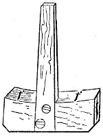
Fig. 162.
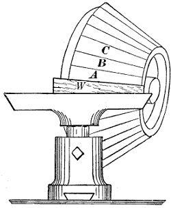
Fig. 163.
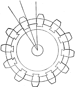
Fig. 164.
To avoid, however, the labor involved in producing these lines for each tooth, two other plans may be adopted. The first is to make a square, such as shown in Fig. 162, the face f f being fitted to the surface c, in Fig. 161, while the edges of its blade coincide with the line referred to; hence the edge of the blade may be placed coincident successively with each point of division, as d d, and the lines for the place of the length of each tooth be drawn. The second plan is to divide off the line a b before removing the body of the pinion from the lathe, and produce, as described, a line for one tooth. A piece of wood may then be placed so that when it lies on the surface of the hand-rest its upper surface will coincide with the line as shown in Fig. 163, in which w is the piece of wood, and a, b, c, &c., the lines referred to. If the teeth are to be glued and bradded to the body, they are first cut out in blocks, left a little larger every way than they are to be when finished, and the surfaces which are to bed on the cone are hollowed to fit it. Then blocks are glued to the body, one and the same relative side of each tooth being set fair to the lines. When the glue is dry, the pinion is again turned on the lathe, the gauge for the cone of the teeth being set in this case to the lines e, f, g in Fig. 160. The pitch circles must then be struck at the ends of the teeth. The turned wheel is then ready to have the curves of the teeth marked. The wheel must now again be divided off on the pitch circle at the large end of the cone into as many equidistant points as there are to be teeth on the wheel, and from these points, and on the same relative side of them, mark off a second series of points, distant from the points of division to an amount equal to the thickness the teeth are required to be. From these points draw in the outline of the teeth (upon the ends of the blocks to form the teeth) at the large end of the cone. Then, by use of the square, shown in Fig. 162, transfer the points of the teeth to the small end of the cone, and trace the outline of the teeth at the small end, taking centres and distances proportionate to the reduced diameter of the pitch circle at the small end, as shown in Fig. 160, where at j are three teeth so marked for the large end, and at k three for the small end, p p representing the pitch circle, and r r a circle for the compass points. The teeth for bevel pinions are sometimes put on by dovetails, as shown in Fig. 164, a plan which possesses points of advantage and disadvantage. Wood shrinks more across the grain than lengthwise with it, hence when the grain of the teeth crosses that of the body with every expansion or contraction of the wood (which always accompanies changes in the humidity of the atmosphere) there will be a movement between the two, because of the unequal expansion and contraction, causing the teeth to loosen or to move. In the employment of dovetails, however, a freedom of movement lengthways of the tooth is provided to accommodate the movement, while the teeth are detained in their proper positions. Again, if in making the founders’ mould, one of the mould teeth should break or fall down when the pattern is withdrawn, a tooth may be removed from the pattern and used by the moulder to build up the damaged part of the mould again. And if the teeth of a bevel pinion are too much undercut on the flank curves to permit the whole pattern from being extracted from the mould without damaging it, dovetailed teeth may be drawn, leaving the body of the pattern to be extracted from the mould last. On the other hand, the dovetail is a costly construction if applied to large wheels. If the teeth are to be affixed by dovetails, the construction varies as follows: Cut out a wooden template of the dovetail, leaving it a little narrower than the thickness of the tooth at the root, and set the template on the cone at a distance from one of the lines a, b, c, Fig. 163, equal to the margin allowed between the edge of the dovetail and the side of the root of the tooth, and set it true by the employment of the square, shown in Fig. 162, and draw along the cone surface of the body lines representing the location of the dovetail grooves. The lines so drawn will give a taper toward x (Fig. 160), providing that, the template sides being parallel, each side is set to the square. While the body is in the lathe, a circle on each end may be struck for the depth of the dovetails, which should be cut out to gauge and to template, so that the teeth will interchange to any dovetail. The bottom of the dovetails need not be circular, but flat, which is easier to make. Dovetail pieces or strips are fitted to the grooves, being left to project slightly above the face of the cone or body. They are drawn in tight enough to enable them to keep their position while being turned in the lathe when the projecting points are turned down level with the cone of the body. The teeth may then be got out as described for glued teeth, and the dovetails added, each being marked to its place, and finally the teeth are cut to shape.
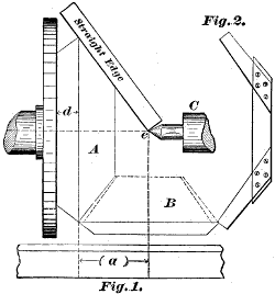
Fig. 165.
In wheels too large to have their cones tested by a bevel gauge, a wooden gauge may be made by nailing two pieces of wood to stand at the required angle as shown in Fig. 165, which is extracted from The American Machinist, or the dead centre c and a straightedge may be used as follows. In the figure the other wheel of the pair is shown dotted in at b, and the dead centre is set at the point where the axes of a and b would meet; hence if the largest diameter of the cone of a is turned to correct size, the cone will be correct when a straightedge applied as shown lies flat on the cone and meets the point of the dead centre e. The pinion b, however, is merely introduced to explain the principle, and obviously could not be so applied practically, the distance to set e, however, is the radius a.
Skew Bevel.[9]—When the axles of the shaft are inclined to each other instead of being in a straight line, and it is proposed to connect and communicate motion to the shafts by means of a single pair of bevel-gears, the teeth must be inclined to the base of the frustra to allow them to come into contact.
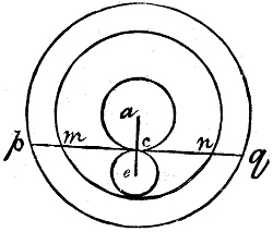
Fig. 166.
To find the line of contact upon a given frustrum of the tangent-cone; let the Fig. 166 be the plane of the frustrum; a the centre. Set off a e equal to the shortest distance between the axes (called the eccentricity), and divide it in c, so that a c is to e c as the mean radius of the frustrum to the mean radius of that with which it is to work; draw c p perpendicular to a e, and meeting the circumference of the conical surface at m; perform a similar operation on the base of the frustrum by drawing a line parallel to c m and at the same distance a c from the centre, meeting the circumference in p.
The line p c is then plainly the line of direction of the teeth. We are also at liberty to employ the equally inclined line c q in the opposite direction, observing only that, in laying out the two wheels, the pair of directions be taken, of which the inclinations correspond.
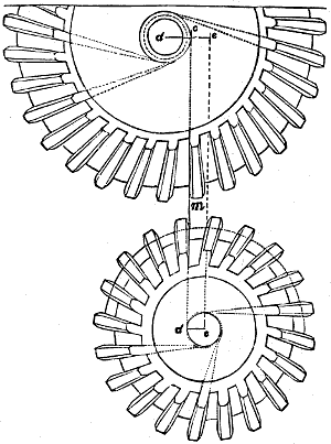
Fig. 167.
Fig. 167 renders this mode of laying off the outlines of the wheels at once obvious. In this figure the line a e corresponds to the line marked by the same letters in Fig. 166; and the division of it at c is determined in the manner directed. The line c m being thus found in direction, it is drawn indefinitely to d. Parallel to this line and from the point c draw e to e, and in this line take the centre of the second wheel. The line c m d gives the direction of the teeth; and if from the centre a with radius at c a circle be described, the direction of any tooth of the wheel will be a tangent to it, as at c, and similarly if a centre e be taken in the line e d, and with radius e d, c e a circle be drawn, the direction of the teeth of the second wheel will be tangents to this last, as at d.
Having thus found the direction of the teeth, these outlines may be formed as in the case of ordinary bevel-wheels and with equal exactness and facility, all that is necessary being to find the curves for the teeth as described for bevel-wheels, and follow precisely the same construction, except that the square, Fig. 162, marking the lines across the cones, requires to be set to the angle for the tooth instead of at a right angle, and this angle may be found by the construction shown in Fig. 167, it being there represented by line d c. It is obvious, however, that the bottoms of the blocks to form the teeth must be curved to bed on the cone along the line d c, Fig. 167, and this may best be done by bedding two teeth, testing them by trial of the actual surfaces.
Then two teeth may be set in as No. 1 and No. 6 in the box shown in Fig. 148, the intermediate ones being dressed down to them.
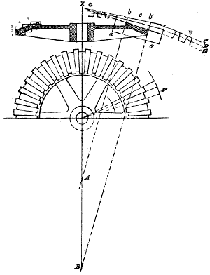
Fig. 168.
Where a bevel-wheel pattern is too large to be constructed in one piece and requires to be built up in pieces, the construction is as in Fig. 168, in which on the left is shown the courses of segments 1, 2, 3, 4, 5, &c., of which the rim is built up (as described for spur wheels), and on the right is shown the finished rim with a tooth, c, in position.
The tooth proper is of the length of face of the wheel as denoted by b b′; now all the lines bounding the teeth must converge to the point x. Suppose, then, that the teeth are to be shaped for curve of face and flank in a box as described for spur-wheel teeth in Fig. 146, then in Fig. 168 let a, a represent the bottom and b b′ the top of the box, and c a tooth in the box, its ends filling the opening in the box at b b′ then the curve on the sides of the box at b′ must be of the form shown at f, and the curve on the sides of the box (at the point b of its length) must be as shown at g, the teeth shown in profile at g and u representing the forms of the teeth at their ends, on the outside of the wheel rim at b′, and on the inside at b; having thus made a box of the correct form on its sides, the teeth may be placed in it and planed down to it, thus giving all the teeth the same curve.
The spacing for the teeth and their fixing may be done as described for the bevel pinion.
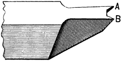
Fig. 169.
To construct a pattern wherefrom to cast an endless screw, worm, or tangent screw, which is to have the worm or thread cut in a lathe.—Take two pieces, each to form one longitudinal half of the pattern; peg and screw them together at the ends, an excess of stuff being allowed at each end for the accommodation of two screws to hold the two halves together while turning them in the lathe, or dogs, if the latter are more convenient, as they might be in a large pattern. Turn the piece down to the size over the top of the thread, after which the core prints are turned. The body thus formed will be ready to have the worm or thread cut, and for this purpose the tools shown in Figs. 169 and 140 are necessary.
That shown in Fig. 169 should be flat on the face similar to a parting tool for cast iron, but should have a great deal more bottom rake, as strength is not so much an object, and the tool is more easily sharpened. It has also in addition two little projections a b like the point of a penknife, formed by filing away the steel in the centre; these points are to cut the fibres of the wood, the severed portion being scraped away by the flat part of the tool.
The degree of side rake given to the tool must be sufficient to let the tool sides well clear the thread or worm, and will therefore vary with the pitch of the worm.
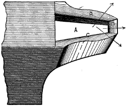
Fig. 170.
The width of the tool must be a shade narrower than the narrowest part of the space in the worm. Having suitably adjusted the change wheels of the lathe to cut the pitch required the parting tool is fed in until the extreme points reach the bottom of the spaces, and a square nosed parting tool without any points or spurs will finish the worm to the required depth. This will have left a square thread, and this we have now to cut to the required curves on the thread or worm sides, and as the cutting will be performed on the end grain of the wood, the top face of the tool must be made keen by piercing through the tool a slot a, Fig. 170, and filing up the bevel faces b, c and d, and then carefully oilstoning them. This tool should be made slightly narrower than the width of the worm space, so that it may not cut on both sides at once, as it would have too great a length of cutting edge.
Furthermore, if the pattern is very large, it will be necessary to have two tools for finishing, one to cut from the pitch line inwards and the other to complete the form from the pitch line outwards. It is advisable to use hard wood for the pattern.
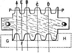
Fig. 171.
If it is decided to cut the thread by hand instead of with these lathe tools, then, the pattern being turned as before, separate the two halves by taking out the screws at the ends; select the half that has not the pegs, as being a little more convenient for tracing lines across. Set out the sections of the thread, a, b, c, and d, Fig. 171, similar to a rack; through the centres of a, b, c, and d, square lines across the piece; these lines, where they intersect the pitch line, will give the centres of teeth on that side: or if we draw lines, as e, f, through the centres of the spaces, they will pass through the centres of the teeth (so to speak) on the other side; in this position complete the outline on that side. It will be found, in drawing these outlines, that the centres of some of the arcs will lie outside the pattern. To obtain support for the compasses, we must fit over the pattern a piece of board such as shown by dotted lines at g h.
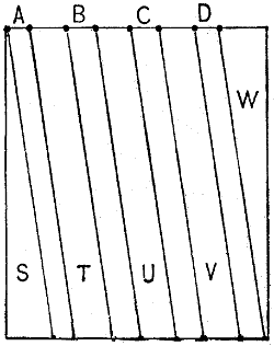
Fig. 172.
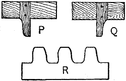
Fig. 173.
It now remains to draw in the top of the thread upon the curved surface of the half pattern; for this purpose take a piece of stiff card or other flexible material, wrap it around the pattern and fix it temporarily by tacks, we then trim off the edges true to the pattern, and mark upon the edges of the card the position of the tops of the thread upon each side; we remove the card and spread it out on a flat surface, join the points marked on the edges by lines as in Fig. 172, replace the card exactly as before upon the pattern, and with a fine scriber we prick through the lines. The cutting out is commenced by sawing, keeping, of course, well within the lines; and it is facilitated by attaching a stop to the saw so as to insure cutting at all parts nearly to the exact depth. This stop is a simple strip of wood and may be clamped to the saw, though it is much more convenient to have a couple of holes in the saw blade for the passage of screws. For finishing, a pair of templates, p and q, Fig. 173, right and left, will be found useful; and finally the work should be verified and slight imperfections corrected by the use of a form or template taking in three spaces, as shown at r in Fig. 173. In drawing the lines on the card, we must consider whether it is a right or left-handed worm that we desire. In the engraving the lines are those suitable for a right-handed thread. Having completed one half of the pattern, place the two halves together, and trace off the half that is uncut, using again the card template for drawing the lines on the curved surface. The cutting out will be the same as before.
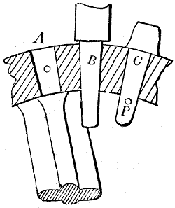
Fig. 174.
As the teeth of cast wheels are, from their deviation from accuracy in the tooth curves and the concentricity of the teeth to the wheel centre, apt to create noise in running, it is not unusual to cast one or both wheels with mortises in the rim to receive wooden teeth. In this case the wheel is termed a mortise wheel, and the teeth are termed cogs. If only one of a pair of wheels is to be cogged, the largest of the pair is usually selected, because there are in that case more teeth to withstand the wear, it being obvious that the wear is greatest upon the wheel having the fewest teeth, and that the iron wheel or pinion can better withstand the wear than the mortise wheel. The woods most used for cogs are hickory, maple, hornbeam and locust. The blocks wherefrom the teeth are to be formed are usually cut out to nearly the required dimensions, and kept in stock, so as to be thoroughly well-seasoned when required for use, and, therefore less liable to come loose from shrinkage after being fitted to the mortise in the wheel. The length of the shanks is made sufficient to project through the wheel rim and receive a pin, as shown in Fig. 174, in which b is a blank tooth, and c a finished tooth inserted in the wheel, the pin referred to being at p. But, if a mortise should fall in an arm of the wheel, this pin-hole must pass through the rim, as shown in the mortise a. The wheel, however, should be designed so that the mortises will not terminate in the arms of the wheel.
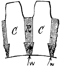
Fig. 175.
Another method of securing the teeth in the mortises is to dovetail them at the small end and drive wedges between them, as shown in Fig. 175, in which c c are two contiguous teeth, r the wheel rim and w w two of the wedges. On account of the dovetailing the wedges exert a pressure pressing the teeth into the mortises. This plan is preferable to that shown in the Fig. 174 inasmuch as from the small bearing area of the pins they become loose quicker, and furthermore there is more elasticity to take up the wear in the case of the wedges.
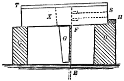
Fig. 176.
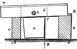
Fig. 177.
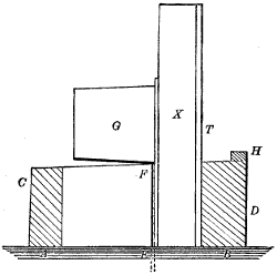
Fig. 178.
The mortises are first dressed out to a uniform size and taper, using two templates to test them with, one of which is for the breadth and the other for the width of the mortise. The height above the wheel requires to be considerably more than that due to the depth of the teeth, so that the surface bruised by driving the cogs or when fitting them into the mortises may be cut off. To avoid this damage as much as possible, a broad-face hammer should be employed—a copper, lead, lignum vitæ, or a raw hide hammer being preferable, and the last the best. The teeth are got out in a box and two guides, such as shown in Figs. 176, 177, and 178, similar letters of reference denoting the same parts in all three illustrations.
In Fig. 176, x is a frame or box containing and holding the operative part of the tooth, and resting on two guides c d. The height of d from the saw table is sufficiently greater than that of c to give the shank g the correct taper, e f representing the circular saw. t is a plain piece of the full size of the box or frame, and serving simply to close up on that side the mortise in the frame. The grain of t should run at a right angle to the other piece of the frame so as to strengthen it. s is a binding screw to hold the cog on the frame, and h is a guide for the edge of the frame to slide against. It is obvious, now, that if the piece d be adjusted at a proper distance from the circular saw e f, and the edge of the frame be moved in contact with the guide h, one side of the tooth shank will be sawn. Then, by reversing the frame end for end, the other side of the shank may be sawn. Turning the frame to a right angle the edges of the cog shank can be sawn from the same box or frame, and pieces c, d, as shown in Fig. 177.
The frame is now stood on edge, as in Fig. 178, and the underneath surfaces sawed off to the depth the saw entered when the shank taper was sawn. This operation requires to be performed on all four sides of the tooth.
After this operation is performed on one cog, it should be tried in the wheel mortises, to test its correctness before cutting out the shanks on all the teeth.
The shanks, being correctly sawn, may then be fitted to the mortises, and let in within 1⁄8 of butting down on the face of the wheel, this amount being left for the final driving. The cogs should be numbered to their places, and two of the mortises must be numbered to show the direction in which the numbers proceed. To mark the shoulders (which are now square) to the curvature of the rim, a fork scriber should be used, and the shanks of the cogs should have marked on them a line coincident with the inner edge of the wheel rim. This line serves as a guide in marking the pin-holes and for cutting the shanks to length; but it is to be remembered that the shanks will pass farther through to the amount of the distance marked by the fork scriber. The holes for the pins which pass through the shanks should be made slightly less in their distances (measured from the nearest edge of the pin-hole) from the shoulders of the cogs than is the thickness of the rim of the wheel, so that when the cogs are driven fully home the pin-holes will appear not quite full circles on the inside of the wheel rim; hence, the pins will bind tightly against the inside of the wheel rim, and act somewhat as keys, locking and drawing the shanks to their seats in the mortises.
In cases where quietness of running is of more consequence than the durability of the teeth, or where the wear is not great, both wheels may be cogged, but as a rule the larger wheel is cogged, the smaller being of metal. This is done because the teeth of the smaller wheel are the most subject to wear. The teeth of the cogged wheel are usually made the thickest, so as to somewhat equalise the strength of the teeth on the two wheels.
Since the power transmitted by a wheel in a given time is composed of the pressure or weight upon the wheel, and the space a point on the pitch circle moves through in the given time, it is obvious that in a train of wheels single geared, the velocities of all the wheels in the train being equal at the pitch circle, the teeth require to be of equal pitch and thickness throughout the train. But when the gearing is compounded the variation of velocity at the pitch circle, which is due to the compounding, has an important bearing upon the necessary strength of the teeth.
Suppose, for example, that a wheel receives a tooth pressure of 100 lbs. at the pitch circle, which travels at the velocity of 100 feet per minute, and is keyed to the same shaft with another wheel whose velocity is 50 feet per minute. Now, in the power transmitted by the two wheels the element of time is 50 for one wheel and 100 for the other, hence the latter (supposing both wheels to have an equal number of teeth in contact with their driver or follower as the case may be) will be twice as strong in proportion to the duty, and it appears that in compounded gearing the strength in proportion to the duty may be varied in proportion as the velocity is modified by compounding of the wheels. Thus, when the velocity at the pitch circle is increased its strength is increased, and per contra when its velocity is decreased its strength is decreased, when considered in proportion to the duty. When, however, the wheels are upon long shafts, or when they overhang the bearing of the shaft, the corner contact will from tension of the shaft, continue much longer than when the shaft is maintained rigid.
It is obvious that if a wheel transmits a certain amount of power, the pressure of tooth upon tooth will depend upon the number of teeth in contact, but since, in the case of very small wheels, that is to say, pinions of the smallest diameter of the given pitch that will transmit continuous motion, it occurs that only one tooth is in continuous contact, it is obvious that each single tooth must have sufficient strength to withstand the whole of the pressure when worn to the limits to which the teeth are supposed to wear. But when the pinion is so small that it has but one tooth in continuous contact, that contact takes place nearer the line of centres and to the root of the tooth, and therefore at a less leverage to the line of fracture, hence the ultimate strength of the tooth is proportionately increased. On the other hand, however, the whole stress of the wheel being concentrated on the arc of contact of one tooth only (instead of upon two or more teeth as in larger wheels), the wear is proportionately greater; hence, in a short time the teeth of the pinion are found to be thinner than those on the other wheel or wheels. The multiplicity of conditions under which small wheels may work with relation to the number of teeth in contact, the average leverage of the point of contact from the root of the tooth, the shape of the tooth, &c., renders it desirable in a general rule to suppose that the whole strain falls upon one tooth, so that the calculation shall give results to meet the requirements when a single tooth only is in continuous contact.
It follows, then, that the thickness of tooth arrived at by calculation should be that which will give to a tooth, when worn to the extreme thinness allowed, sufficient strength (with a proper margin of safety) to transmit the whole of the power transmitted by the wheel.
The margin (or factor) of safety, or in other words, the number of times the strength of the tooth should exceed the amount of power transmitted, varies (according to the conditions under which the wheels work) between 5 and 10.
The lesser factor may be used for slow speeds when the power is continuously and uniformly transmitted. The greater factor is necessary when the wheels are subjected to violent shocks and the direction of revolution requires to be reversed.
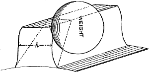
Fig. 179.
In pattern-cast teeth, contact between the teeth of one wheel and those of the other frequently occurs at one corner only, as shown in Fig. 179, and the line of fracture is in the direction denoted by the diagonal dotted lines. The causes of this corner contact have been already explained, but it may be added that as the wheels wear, the contact extends across the full breadths of the teeth, and the strength in proportion to the duty, therefore, steadily increases from the time the new wheels have action until the wear has caused contact fully across the breadth. Tredgold’s rule for finding the proper thickness of tooth for a given stress upon cast-iron teeth loaded at the corner as in Fig. 179 and supposed to have a velocity of three feet per second of time, is as follows:—
Rule.—Divide the stress in pounds at the pitch circle by 1500, and the square root of the quotient is the required thickness of tooth in inches or parts of an inch.
In the results obtained by the employment of this rule, an allowance of one-third the thickness for wear, and the margin for safety is included, so that the thickness of tooth arrived at is that to be given to the actual tooth. Further, the rule supposes the breadth of the tooth to be not less than twice the height of the same, any extra breadth not affecting the result (as already explained), when the pressure falls on a corner of the tooth.
In practical application, however, the diameter of the wheel at the pitch circle is generally, or at least often a fixed quantity, as well as the amount of stress, and it will happen as a rule that taking the stress as a fixed element and arriving at the thickness of the tooth by calculation, the required diameter of wheel, or what is the same thing, its circumference, will not be such as to contain the exact number of teeth of the thickness found by the calculation, and still give the desired amount of side clearance. It is desirable, therefore, to deal with the stress upon the tooth at the pitch circle, and the diameter, radius, or circumference of the pitch circle, and its velocity, and deduce therefrom the required thickness for the teeth, and conform the pitch to the requirements as to clearance from the tooth thickness thus obtained.
To deduce the thickness of the teeth from these elements we have Robertson Buchanan’s rule, which is as follows:—
Find the amount of horse-power employed to move the wheel, and divide such horse-power by the velocity in feet per second of the pitch line of the wheel. Extract the square root of the quotient, and three-fourths of this root will be the least thickness of the tooth. To the result thus obtained, there must be added the allowance for wear of the teeth and the width of the space including the clearance which will determine the number of teeth in the wheel.
In conforming strictly to this rule the difficulty is met with that it would give fractional pitches not usually employed and difficult to measure on an existing wheel. Cast wheels kept on hand or in stock by machinists have usually the following standard:—
Beginning with an inch pitch, the pitches increase by 1⁄8 inch up to 3-inch pitch, from 3 to 4-inch pitches the increase is by 1⁄4 inch, and from 4-inch pitch and upwards the increase is by 1⁄2 inch. Now, under the rule the pitches would, with the clearance made to bear a certain proportion to the pitch, be in odd fractions of an inch.
It appears then, that, if in a calculation to obtain the necessary thickness of tooth, the diameter of the pitch circle is not an element, the rule cannot be strictly adhered to unless the diameter of the pitch circle be varied to suit the calculated thickness of tooth; or unless either the clearance, factor of safety, or amount of tooth thickness allowed for wear be varied to admit of the thickness of tooth arrived at by the calculation. But if the diameter of the pitch circle is one of the elements considered in arriving at the thickness of tooth requisite under given conditions, the pitch must, as a rule, either be in odd fractions, or else the allowance for wear, factor of safety, or amount of side clearance cannot bear a definite proportion to the pitch. But the allowance for clearance is in practice always a constant proportion of the pitch, and under these circumstances, all that can be done when the circumstances require a definite circumference of pitch circle, is to select such a pitch as will nearest meet the requirements of tooth thickness as found by calculation, while following the rule of making the clearance a constant proportion of the pitch. When following this plan gives a thinner tooth than the calculation calls for, the factor of safety and the allowance for wear are reduced. But this is of little consequence whenever more than one tooth on each wheel is in contact, because the rules provide for all the stress falling on one tooth. When, however, the number of teeth in the pinion is so small that one tooth only is in contact, it is better to select a pitch that will give a thicker rather than a thinner tooth than called for by the calculation, providing, of course, that the pitch be less than the arc of contact, so that the motion shall be continuous.
But when the pinions are shrouded, that is, have flanges at each end, the teeth are strengthened; and since the wear will continue greater than in wheels having more teeth in contact, the shrouding may be regarded as a provision against breakage in consequence of the reduction of tooth thickness resulting from wear.
In the following table is given the thickness of the tooth for a given stress at the pitch circle, calculated from Tredgold’s rule for teeth supposed to have contact when new at one corner only.
Stress in lbs. at pitch circle. Thickness of tooth in inches. Actual pitches to which wheels may be made.
400 .52 1 1⁄8 to 1 1⁄4
800 .75 1 1⁄2 „ 1 5⁄8
1,200 .90 1 7⁄8 „ 2
1,600 1.03 2 „ 2 1⁄8
2,000 1.15 2 1⁄4 „ 2 3⁄8
2,400 1.26 2 1⁄2 „ 2 5⁄8
2,800 1.36 2 5⁄8 „ 2 3⁄4
3,200 1.43 2 7⁄8 „ 3
3,600 1.56 3 1⁄8 „ 3 1⁄4
4,000 1.63 3 1⁄4 „ 3 3⁄8
4,400 1.70 3 3⁄8 „ 3 1⁄2
4,800 1.78 3 1⁄2 „ 3 5⁄8
5,200 1.86 3 5⁄8 „ 3 3⁄4
5,600 1.93 3 3⁄4 „ 4
6,000 2.00 4 „ 4 1⁄4
In wheels that have their teeth cut to form in a gear-cutting machine the thickness of tooth at any point in the depth is equal at any point across the breadth; hence, supposing the wheels to be properly keyed to their shafts so that the pitch line across the breadth of the wheel stands parallel to the axis of the shaft, the contact of tooth upon tooth occurs across the full breadth of the tooth.
As the practical result of these conditions we have three important advantages: first, that the stress being exerted along the full breadth of the tooth instead of on one corner only, the tooth is stronger (with a given breadth and thickness) in proportion to the duty; second, that with a given pitch, the thickness and therefore the margin for safety and allowance for wear are increased, because the tooth may be increased in thickness at the expense of the clearance, which need be merely sufficient to prevent contact on both sides of the spaces so as to prevent the teeth from locking in the spaces; and thirdly, because the teeth will not be subject to sudden impacts or shocks of tooth upon tooth by reason of back lash.
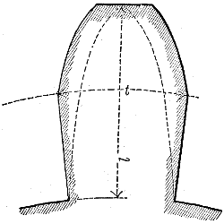
Fig. 180.
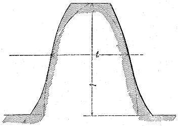
Fig. 181.
In determining the strength of cut gear-teeth we may suppose the weight to be disposed along the face at the extreme height of the tooth, in which case the theoretical shape of the tooth to possess equal strength at every point from the addendum circle to the root would be a parabola, as shown by the dotted lines in Fig. 180, which represents a tooth having radial flanks. In this case it is evident that the ultimate strength of the tooth is that due to the thickness at the root, because it is less than that at the pitch circle, and the strength, as a whole, is not greater than that at the weakest part. But since teeth with radial flanks are produced, as has been shown, with a generating circle equal in diameter to the radius of the pinion, and since with a generating circle bearing that ratio of diameter to diameter of pitch circle the acting part of the flank is limited, it is usual to fill in the corners with fillets or rounded corners, as shown in Fig. 129; hence, the weakest part of the tooth will be where the radial line of the flank joins the fillet and, therefore, nearer the pitch circle than is the root. But as only the smallest wheel of the set has radial flanks and the flanks thicken as the diameter of the wheels increase, it is usual to take the thickness of the tooth at the pitch circle as representing the weakest part of the tooth, and, therefore, that from which the strength of the tooth is to be computed. This, however, is not actually the case even in teeth which have considerable spread at the roots, as is shown in Fig. 181, in which the shape of the tooth to possess equal strength throughout its depth is denoted by the parabolic dotted lines.
Considering a tooth as simply a beam supporting the strain as a weight we may calculate its strength as follows:—
Multiply the breadth of the tooth by the square of its thickness, and the product by the strength of the material, per square inch of section, of which the teeth are composed, and divide this last product by the distance of the pitch line from the root, and the quotient will give a tooth thickness having a strength equal to the weight of the load, but having no margin for safety, and no allowance for wear; hence, the result thus obtained must be multiplied by the factor of safety (which for this class of tooth may be taken as 6), and must have an additional thickness added to allow for wear, so that the factor of safety will be constant notwithstanding the wear.
Another, and in some respects more convenient method, for obtaining the strength of a tooth, is to take the strength of a tooth having 1-inch pitch, and 1 inch of breadth, and multiply this quantity of strength by the pitch and the face of the tooth it is required to find the strength of, both teeth being of the same material.
Example.—The safe working pressure for a cast-iron tooth of an inch pitch, and an inch broad will transmit, being taken as 400 lbs., what pressure will a tooth of 3⁄4-inch pitch and 3 inches broad transmit with safety?
Here 400 lbs. × 3⁄4 pitch × 3 breadth = 900 = safe working pressure of tooth 3⁄4-inch pitch and 3 inches broad.
Again, the safe working pressure of a cast-iron tooth, 1 inch in breadth and of 1-inch pitch, being considered as 400 lbs., what is the safe working pressure of a tooth of 1-inch pitch and 4-inch breadth?
Here 400 × 1 × 4 = 1600.
The philosophy of this is apparent when we consider that four wheels of 1-inch pitch and an inch face, placed together side by side, would constitute, if welded together, one wheel of an inch pitch and 4 inches face. (The term face is applied to the wheel, and the term breadth to the tooth, because such is the custom of the workshop, both terms, however, mean, in the case of spur-wheels, the dimension of the tooth in a direction parallel to the axis of the wheel shaft or wheel bore.)
The following table gives the safe working pressures for wheels having an inch pitch and an inch face when working at the given velocities, S.W.P. standing for “safe working pressure:”—
Velocity of pitch circle in feet per second. S.W.P. for cast-iron spur gears. S.W.P. for spur mor- tise gears. S.W.P. for cast-iron bevel gears. S.W.P. for bevel mortise gears.
2 368 178 258 178
3 322 178 225 157
6 255 178 178 125
12 203 142 142 99
18 177 124 124 87
24 161 113 113 79
30 150 105 105 74
36 140 98 98 69
42 133 93 93 65
48 127 88 88 62
For velocities less than 2 feet per second, use the same value as for 2 feet per second.
The proportions, in terms of the pitch, upon which this table is based, are as follows:—
Thickness of iron teeth . 395 of the pitch.
„ wooden „ . 595 „
Height of addendum . 28 „
Depth below pitch line . 32 „
The table is based upon 400 lbs. per inch of face for an inch pitch, as the safe working pressure of mortise wheel teeth or cogs; it may be noted that there is considerable difference of opinion. They are claimed by some to be in many cases practically stronger than teeth of cast iron. This may be, and probably is, the case when the conditions are such that the teeth being rigid and rigidly held (as in the case of cast-iron teeth), there is but one tooth on each wheel in contact. But when there is so nearly contact between two teeth on each wheel that but little elasticity in the teeth would cause a second pair of teeth to have contact, then the elasticity of the wood would cause this second contact. Added to this, however, we have the fact that under conditions where violent shock occurs the cog would have sufficient elasticity to give, or spring, and thus break the shock which cast iron would resist to the point of rupture. It is under these conditions, which mainly occur in high velocities with one of the wheels having cast teeth, that mortise wheels, or cogging, is employed, possessing the advantage that a broken or worn-out tooth, or teeth, may be readily replaced. It is usual, however, to assign to wooden teeth a value of strength more nearly equal to that of its strength in proportion to that of cast iron; hence, Thomas Box allows a wood tooth a value of about 3⁄10ths the strength of cast iron; a value as high as 7⁄10ths is, however, assigned by other authorities. But the strength of the tooth cannot exceed that at the top of the shank, where it fits into the mortise of the wheel, and on account of the leverage of the pressure the width of the mortise should exceed the thickness of the tooth.
In some practice, the mortise teeth, or cogs, are made thicker in proportion to the pitch than the teeth on the iron wheel; thus Professor Unwin, in his “Elements of Machine Design,” gives the following as “good proportions”:—
Thickness of iron teeth 0.395 of the pitch.
„ wood cogs 0.595 „ „
which makes the cogs 2⁄10ths inch thicker than the teeth.
The mortises in the wheel rim are made taper in both the breadth and the width, which enables the tooth shank to be more accurately fitted, and also of being driven more tightly home, than if parallel. The amount of this taper is a matter of judgment, but it may be observed that the greater the taper the more labor there is involved in fitting, and the more strain there is thrown upon the pins when locking the teeth with a given amount of strain. While the less the taper, the more care required to obtain an accurate fit. Taking these two elements into consideration, 1⁄8th inch of taper in a length of 4 inches may be given as a desirable proportion.
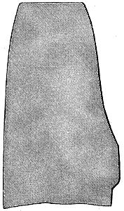
Fig. 182.
As an evidence of the durability of wooden teeth, there appeared in Engineering of January 7th, 1879, the illustration shown in Fig. 182, which represents a cog from a wheel of 14 ft. 1⁄2 in. diameter, and having a 10-inch face, its pinion being 4 ft. in diameter. This cog had been running for 261⁄2 years, day and night; not a cog in the wheel having been touched during that time. Its average revolutions were 38 per minute, the power developed by the engine being from 90 to 100 indicated horse-power. The teeth were composed of beech, and had been greased twice a week, with tallow and plumbago ore.
Since the width of the face of a wheel influences its wear (by providing a larger area of contact over which the pressure may be distributed, as well as increasing the strength), two methods of proportioning the breadth may be adopted. First, it may be made a certain proportion of the pitch; and secondly, it may be proportioned to the pressure transmitted and the number of revolutions. The desirability of the second is manifest when we consider that each tooth will pass through the arcs of contact (and thus be subjected to wear) once during each revolution; hence, by making the number of revolutions an element in the calculation to find the breadth, the latter is more in proportion to the wear than it would be if proportioned to the pitch.
It is obvious that the breadth should be sufficient to afford the required degree of strength with a suitable factor of safety, and allowance for wear of the smallest wheel in the pair or set, as the case may be.
According to Reuleaux, the face of a wheel should never be less than that obtained by multiplying the gross pressure, transmitted in lbs., by the revolutions per minute, and dividing the product by 28,000.
In the case of bevel-wheels the pitch increases, as the perimeter of the wheel is approached, and the maximum pitch is usually taken as the designated pitch of the wheel. But the mean pitch is that which should be taken for the purposes of calculating the strength, it being in the middle of the tooth breadth. The mean pitch is also the diameter of the pitch circle, used for ascertaining the velocity of the wheel as an element in calculating the safe pressure, or the amount of power the wheel is capable of transmitting, and it is upon this basis that the values for bevel-wheels in the above table are computed.
In many cases it is required to find the amount of horse-power a wheel will transmit, or the proportions requisite for a wheel to transmit a given horse-power; and as an aid to the necessary calculations, the following table is given of the amount of horse-power that may be transmitted with safety, by the various wheels at the given velocities, with a wheel of an inch pitch and an inch face, from which that for other pitches and faces may be obtained by proportion.
TABLE SHOWING THE HORSE-POWER WHICH DIFFERENT KINDS OF GEAR-WHEELS OF ONE INCH PITCH AND ONE INCH FACE WILL SAFELY TRANSMIT AT VARIOUS VELOCITIES OF PITCH CIRCLE.
Velocity of Pitch Circle in Feet per Second. Spur-Wheels. H.P. Spur Mortise Wheels. H.P. Bevel-Wheels. H.P. Bevel Mortise Wheels. H.P.
2 1.3 38 .6 47 .9 38 .6 47
3 1.7 56 .9 71 1.2 27 .8 56
6 2.7 82 1.7 6 1.7 6 1.3 63
12 4.4 3 3.1 3.1 2.1 6
18 5.7 93 4.0 58 4.0 58 2.8 47
24 7.0 25 4.9 31 4.9 31 3.4 47
30 8.1 82 5.7 27 5.7 27 4.0 36
36 9.1 63 6.4 14 6.4 14 4.5 16
42 10.1 56 7.1 02 7.1 02 4.9 63
48 11.0 83 7.6 80 7.6 80 5.4 11
In this table, as in the preceding one, the safe working pressure for 1-inch pitch and 1-inch breadth of face is supposed to be 400 lbs.
In cast gearing, the mould for which is made by a gear moulding machine, the element of draft to permit the extraction of the pattern is reduced: hence, the pressure of tooth upon tooth may be supposed to be along the full breadth of the tooth instead of at one corner only, as in the case of pattern-moulded teeth. But from the inaccuracies which may occur from unequal contraction in the cooling of the casting, and from possible warping of the casting while cooling, which is sure to occur to some extent, however small the amount may be, it is not to be presumed that the contact of the teeth of one wheel will be in all the teeth as perfect across the full breadth as in the case of machine-cut teeth. Furthermore, the clearance allowed for machine-moulded teeth, while considerably less than that allowed for pattern-moulded teeth, is greater than that allowed for machine-cut teeth; hence, the strength of machine-moulded teeth in proportion to the pitch lies somewhere between that of pattern-moulded and machine-cut teeth—but exactly where, it would be difficult to determine in the absence of experiments made for the purpose of ascertaining.
It is not improbable, however, that the contact of tooth upon tooth extends in cast gears across at least two-thirds of the breadth of the tooth, in which case the rules for ascertaining the strength of cut teeth of equal thickness may be employed, substituting 2⁄3rds of the actual tooth breadth as the breadth for the purposes of the calculation.
If instead of supposing all the strain to fall upon one tooth and calculating the necessary strength of the teeth upon that basis (as is necessary in interchangeable gearing, because these conditions may exist in the case of the smallest pinion that can be used in pitch), the actual working condition of each separate application of gears be considered, it will appear that with a given diameter of pitch circle, all other things being equal, the arc of contact will remain constant whatever the pitch of the teeth, or in other words is independent of the pitch, and it follows that when the thickness of iron necessary to withstand (with the allowances for wear and factor of safety) the given stress under the given velocity has been determined, it may be disposed in a coarse pitch that will give one tooth always in contact, or a finer pitch that will give two or more teeth always in contact, the strength in proportion to the duty remaining the same in both cases.
In this case the expense of producing the wheel patterns or in trimming the teeth is to be considered, because if there are a train of wheels the finer pitch would obviously involve the construction and dressing to shape of a much greater number of teeth on each wheel in the train, thus increasing the labor. When, however, it is required to reduce the pinion to a minimum diameter, it is obvious that this may be accomplished by selecting the finer pitch, because the finer the pitch, the less the diameter of the wheel may be. Thus with a given diameter of pitch circle it is possible to select a pitch so fine that motion from one wheel may be communicated to another, whatever the diameter of the pitch circle may be, the limit being bounded by the practicability of casting or producing teeth of the necessary fineness of pitch. The durability of a wheel having a fine pitch is greater for two reasons: first, because the metal nearest the cast surface of cast iron is stronger than the internal metal, and the finer pitch would have more of this surface to withstand the wear; and second, because in a wheel of a given width there would be two points, or twice the area of metal, to withstand the abrasion, it being remembered that the point of contact is a line which partly rolls and partly slides along the depth of the tooth as the wheel rotates, and that with two teeth in contact on each wheel there are two of such lines. There is also less sliding or rubbing action of the teeth, but this is offset by the fact that there are more teeth in contact, and that there are therefore a greater number of teeth simultaneously rubbing or sliding one upon the other.
But when we deal with the number of teeth the circumstances are altered; thus with teeth of epicycloidal form it is manifestly impossible to communicate constant motion with a driving wheel having but one tooth, or to receive motion on a follower having but one tooth. The number of teeth must always be such that there is at all times a tooth of each wheel within the arc of action, or in contact, so that one pair of teeth may come into contact before the contact of the preceding teeth has ceased.
In the construction of wheels designed to transmit power as well as simple motion, as is the case with the wheels employed in machine work, however, it is not considered desirable to employ wheels containing a less number of teeth than 12. The diameter of the wheel bearing such a relation to the pitch that both wheels containing the same number of teeth (12), the motion will be communicated from one to the other continuously.
It is obvious that as the number of teeth in one of the wheels (of a pair in gear) is increased the number of teeth in the other may be (within certain limits) diminished, and still be capable of transmitting continuous motion. Thus a pinion containing, say 8 teeth, may be capable of receiving continuous motion from a rack in continuous motion, while it would not be capable of receiving continuous motion from a pinion having 4 teeth; and as the requirements of machine construction often call for the transmission of motion from one pinion to another of equal diameters, and as small as possible, 12 teeth are the smallest number it is considered desirable for a pinion to contain, except it be in the case of an internal wheel, in which the arc of contact is greater in proportion to the diameters than in spur-wheels, and continuous motion can therefore be transmitted either with coarser pitches or smaller diameters of pinion.
For convenience in calculating the pitch diameter at pitch circle, or pitch diameter as it is termed, and the number of teeth of wheels, the following rules and table extracted from the Cincinnati Artisan and arranged from a table by D. A. Clarke, are given. The first column gives the pitch, the following nine columns give the pitch diameters of wheels for each pitch from 1 tooth to 9. By multiplying these numbers by 10 we have the pitch diameters from 10 to 90 teeth, increasing by tens; by multiplying by 100 we likewise have the pitch diameters from 100 to 900, increasing by hundreds.