Volume 1 — Chapter IX.—DRIVING WORK IN THE LATHE. (continued 2)
Reading edition
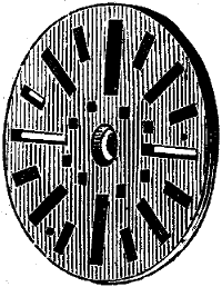
Fig. 860.
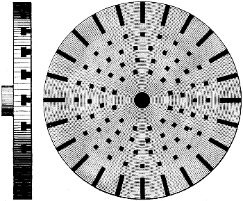
Fig. 861.
The chuck plate is simply a face as large in diameter as the lathe will swing, and is sometimes termed the large face plate. Chuck plates for smaller lathes, as 30 inches swing, or less, are sometimes provided with numerous round or square holes to receive the bolts which hold the work, but usually with slots and holes as in Fig. 860. The larger sizes of chuck plates are similarly formed, but are sometimes provided with short slots that meet the circumference of the plate as in Fig. 861, which represents a chuck plate of the Whitworth pattern. The face of the chuck plate must be maintained true in order that true work may be produced, and it is necessary when putting it upon the lathe to carefully clean its threads and those of the live spindle, as, on account of its large diameter, a very little dirt between it and the live spindle will throw it considerably out of truth at the circumference.
It is better if there be any error in a chuck plate or face plate that it be hollow rather than rounding when tested with a straightedge, because in that case a given amount of error in the plate will produce less error in the work.
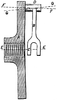
Fig. 862.
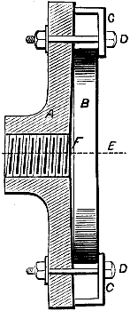
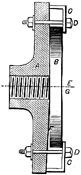
Fig. 863. Fig. 864.
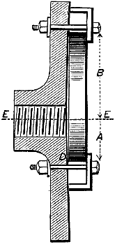
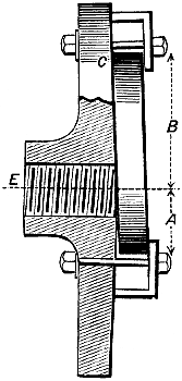
Fig. 865. Fig. 866.
In Fig. 862, for example, a represents a chuck plate hollow across the face, and b a link requiring to be bored through its double eye c, the centre line of the lathe being line e e, and the centre line of the hole in the hub d of the link being denoted by f, and as e and f are not parallel one to the other it is obvious that the holes will not be parallel. Suppose, now, that the chuck face was rounding, and the centre line of d would stand at g g, and the holes in c and d would be out of true in the opposite direction. In this case the error would be equal, but suppose we have a ring or disc such as b in Fig. 863 to chuck by bolts and plates c, d and it will be chucked true, notwithstanding that the face of the plate is hollow. But were the face of the plate rounding the disc may be chucked as in Fig. 864, the face f of the work not being held at a right angle to the line of centres e as it is in Fig. 863. The truth of the chucking in Fig. 864 depends upon whether the clamps c were screwed up with equal force upon the work. A hollow chuck plate will lose this advantage in proportion as the work covers more of one side of the chuck plate than it does of the other, but in any event it will chuck more true than a rounding one. Suppose we have, for example, a ring chucked eccentrically as in Figs. 865 and 866, the chuck being as much hollow in the one case as it is rounding in the other, and that shown in Fig. 866 will stand out of true to an amount greater than the chuck is in an equal amount of its radius. While that shown in Fig. 865 would be nearer true than the chuck is in an equal length of its radius, both amounts being in proportion to the length of the line a to that of line b.
If the chuck plate is known to be either rounding or hollow, pieces of paper of sufficient thickness to remedy the error may be placed at c and d respectively. It is better, however, to true up the faces of plates so that the surface of the work bolted against it will be true and stand at a right angle to the line of lathe centres.
In truing up a face plate, the bearings of the live spindle should be adjusted so that there is no play on them, and the screw or other device used to prevent end motion to the live spindle should be properly adjusted.
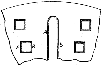
Fig. 867.
A bar or rod of iron should also be placed between the lathe centres to further steady the live spindle, and the square holes or radial slots should have the edges rounded or bevelled off, as shown in Fig. 867, so that when the tool point strikes the sides a of the holes or slots it will leave its cut gradually and not with a sudden jerk or jump, while, when it again takes its cut on the side b, it will also meet it gradually and will not meet the sand or hard skin on the face of the casting, which would rapidly dull the tool.
In facing or truing up a chuck plate, the feed nut should be put in gear with the feed screw or feed spindle, and the cut should be put on by revolving the feed spindle or feed screw. This will take up any lost motion in the feeding mechanism, after which the carriage may, if there are devices for the purpose, be locked to the lathe bed so as to prevent its moving.
It is better that the thread of the chuck be not too tight a fit upon that on the lathe spindle, the radial face of the chuck hub and of the cone spindle collar being relied upon to set the chuck true, because it is somewhat difficult to produce threads so true as to hold the faces true.
To preserve the threads both upon the chuck bore and the lathe spindle from undue wear, the chuck when taken off the lathe should be stood on edge so that falling dust may not accumulate in the thread. Before putting the chuck upon the lathe spindle the threads of both and the radial faces of the chuck hub and cone spindle collar should be carefully cleaned, because the presence of any dirt or dust on those faces will throw the face of the chuck plate out of true to an amount that may be of importance at and near the chuck’s circumference.
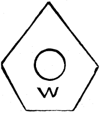
Fig. 868.
As an example of simple chucking on a face plate, or chuck plate, let it be required to bore, cut a thread in the bore, and recess the piece of work shown in Fig. 868, the radial faces being already true planes not requiring to be turned.
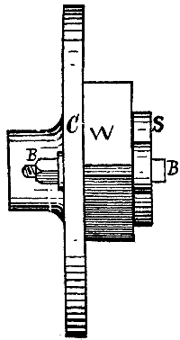
Fig. 869.
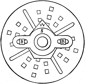
Fig. 870.
This could be held as shown in Fig. 869, in which c is the chuck plate, w the work, s a strap plate, and b, b are bolts and nuts, a face view of the work already chucked being shown in Fig. 870. The surface of the work being bolted direct against the face of the chuck plate will be held true to that face, and all that is necessary is to set it true concentrically. While performing this setting, the work should not be bolted too firmly, but just firm enough to permit of its being moved on the chuck plate by light blows, the final tightening of the clamps being effected after the work is set true. The bolts should be tightened upon the work equally, otherwise one end of the plate will grip the work firmly, while the other being comparatively slack, the work will be apt to move under the pressure of a heavy cut.
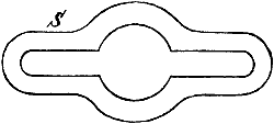
Fig. 871.
A form of strap not unusually employed for work chucked in this manner is shown in Fig. 871, its advantage being that it is capable of more adjustment about the chuck plate, because the slots afford a greater range for the bolts to come even with the holes in the chuck plate.
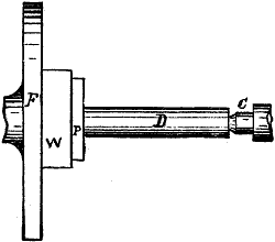
Fig. 872.
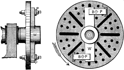
Fig. 873.
If the work be light, it may be held to the face plate while the holding or clamping plates are applied as shown in Fig. 872, in which f is the face plate or chuck plate, w the work, p a plate of iron, d a rod, and c the back lathe centre. The latter is forced out by the hand wheel of the tailstock with sufficient force to hold the work by friction while the bolts and plates are applied. It is obvious, however, that if the work has no hole in its centre, the plate p may be dispensed with, and that if a strap plate, such as shown in Fig. 871, be employed, it must first be hung on the tail spindle so that it may be passed over the rod d to the work. Strap plates are suitable for work not exceeding about 6 inches in diameter. For larger work, bolts and plates are used, as shown, for example, in Fig. 873, which represents a piece of work w held to the chuck plate by plates p and bolts b, there being at e e packing pieces or pieces of iron to support those ends of the clamps or clamping plates p. It is necessary that these packing pieces e be of such a height as to cause the plates p to stand parallel to the face of the chuck for the following reasons:—
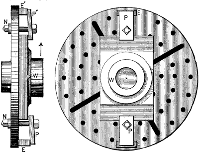
Fig. 874.
Suppose that in Fig. 874, w is a piece of work clamped to the chuck plate, and that packing piece e is too high, and packing piece e′ is too low, as shown, both pieces throwing the plates p out of level, then in setting the hole in the work to run true it will be found difficult to move it in the direction of the arrow, because moving it in that direction acts to force it farther under plate p′, and therefore, to tighten its nut. In the case of plate p, the packing piece e will be gripped by the plate more firmly than the work is, which will be held too loosely, receiving so little of the plate pressure as to be liable to move under the pressure of the tool cut. It is better, however, that the packing piece be slightly above, rather than below the level of the work surface. The position of the plates with relation to the work should be such as to drive rather than to pull it, which is accomplished in narrow work by placing them as in Fig. 873.
The position of the bolts should be as close as possible or convenient to the work, because in that case a larger proportion of its pressure falls upon the work than upon the packing piece. For the same reason, the packing piece should be placed at the end of the plates. This explains one reason why it is preferable that the packing piece be slightly above rather than below the level of the work surface, because, the bolt being nearer to the work than to the packing piece, will offset in its increased pressure on the work the tendency of the packing piece to take the most bolt pressure on account of standing the highest.
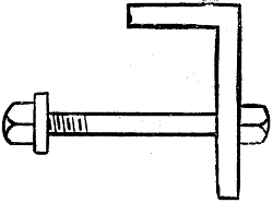
Fig. 875.
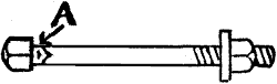
Fig. 876.
If a packing piece of the necessary height be not at hand, two or more pieces may be used, one being placed upon the other. Another plan is to bend the end of the clamping plate around, as in Fig. 875, in which case a less number of packing pieces will be required, or, in case the part bent around is of the right length or height, packing pieces may be dispensed with altogether. This is desirable because it is somewhat difficult to hold simultaneously the plate in its proper position and the packing pieces in place while the nut is screwed up, there being too many operations for the operator’s two hands. To facilitate this handling, the nuts upon the bolts should not be a tight fit, because, in that case, the bolt will turn around in the bolt holes or slot of the chuck, requiring a wrench to hold the head of the bolt while the nut is screwed up, which, with holding the plate, would be more than one operator could perform. If the holes in the chuck plate are square, as they should be, the bolt may be made square under the head, as in Fig. 876 at a, which will prevent it from turning in the hole. This, however, necessitates that the head of the bolt be placed at the back of the chuck, the nut end of the bolt being on the work side, which is permissible providing that the bolt is not too long, for in that case the end of the bolt projecting beyond the nut would prevent the slide rest from traversing close up to the work, which would necessitate that the cutting tools stand farther out from the slide rest, which is always undesirable. Bolts that are not square under the head should, therefore, be placed with the head in the work side of the chuck plate, because it is of little consequence if the bolt ends project beyond the nuts at the back of the chuck plate.
The heads of the bolts should be of larger diameter than the nuts, because the increased area under the head will tend to prevent the bolt from turning when the nut is screwed up.
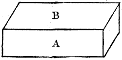
Fig. 877.
It sometimes happens that a projection on the work prevents the surface that should go against the surface of the chuck plate from meeting the latter. In this case, what are known as parallel pieces are employed. These are pieces of metal, such as shown in Fig. 877, the thickness a varying from the width b so as to be suitable for work requiring to stand at different distances from the chuck plate surface, it being always desirable to have the work held as near as possible to the chuck plate so that it may not overhang the live spindle bearings any more than necessary.
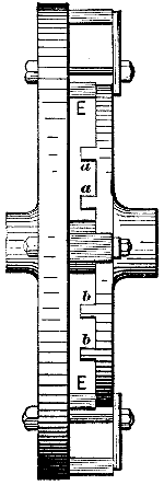
Fig. 878.
An example of chucking with bolts and plates and with parallel pieces is given in Fig. 878, in which the work has projections a, a and b, b, which prevent it going against the face of the chuck; e, e are the parallel pieces which, being of equal thickness, hold the inside face of the work parallel to the chuck face.
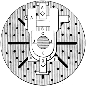
Fig. 879.
Another example of the employment of parallel pieces is shown in Fig. 879, which represents a connecting rod strap with its brasses in place, and chucked to be bored. b is a small block of iron inserted so that the key may bind the brasses in the strap and p p is one parallel piece, the other being hidden beneath the key and gib. The object in this case is to chuck the brasses true with the face a of the strap, the plates s being placed directly above or over the parallel pieces. This is a point requiring the strictest attention, for otherwise the pressure of the clamping plates will bend both the work and the chuck plate.
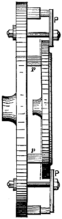
Fig. 880.
In Fig. 880, for example, the parallel pieces being placed at p, p, and the clamping plates at p, p, the pressure of the latter will bend the work as denoted by the dotted lines, and the chuck plate in the opposite direction, and in this case the work being weaker than the chuck plate will bend the most.
As a result the face of the work will not be true when released from the pressure of the bolts and nuts holding it. Parallel pieces should therefore always be placed directly beneath the clamping plates, especially in the case of light work, because if they be but an inch away the work will be bent, or spring as it is termed, from the holding plate pressure. In very large work the want of truth thus induced would be practically discernible, even though the work be quite thick, as, say, three inches, if the parallel pieces were as much as, say, 6 inches from the holding plates.
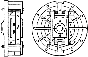
Fig. 881.
Fig. 881 shows an example of chucking by means of parallel strips in conjunction with parallel pieces. b, b are a pair of brasses clamped by the strips s, s, which are bolted together by the bolts a, a; p, p are the parallel pieces.
The strips being thus held parallel to the surface of the chuck plate, all that is necessary is to set the flanges of the work fair against the surface of the strips and true with the dotted circle, and the brass bore will be bored at a true right angle to the inside face of the flange. If the inside face of the brasses was true, the parallel pieces might be omitted, but this is rarely the case.
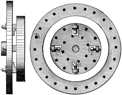
Fig. 882.
An excellent example of bolt and plate chucking is given in a heavy ring of, say, three feet diameter, and 5 or 6 inches cross section, requiring to be turned quite true, and of equal thickness all over. This job may be chucked in three different ways; for example, in Fig. 882, a, b, c, d are four-chucking dogs, so holding the work that its two radial faces and outside diameter may be turned. This being done, four more dogs may be placed to grip the diameter of the work, and the inside ones may then be removed and the bore turned out. In this way the work would not be unchucked until finished. There is danger, however, that the dogs applied outside may spring the work out of true, in which case it would require setting by a pointer in the slide rest.
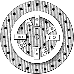
Fig. 883.
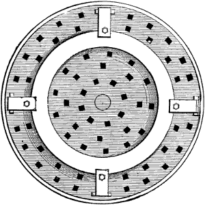
Fig. 884.
Another plan would be to hold the work by dogs applied on the outside, and turn the bore and both of the faces. To these fasten four plates on the chuck plate, and turn their ends to the size of the bore and place the work on them, as in Fig. 883, in which a, b, c, d are the four plates, and are clamping plates. This plan is often employed, but it is not a desirable one in heavy work, because the weight of the work is quite apt to move the plates during its setting. A better plan than either of these is to first turn off one face and then turn the work around in the lathe and hold it as in Fig. 884. The bore may then be turned, and all that part of the face not covered by the plates. Four holding plates must then be applied with the bolts within the bore, and when screwed firmly down the outside plates may be removed, leaving the work free to have the remainder of its face and its circumference turned up. In this way the work may be turned more true than by either of the two previously described methods, because it has no opportunity to move or become out of true.
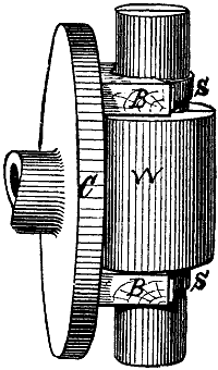
Fig. 885.
Cylindrical work to be chucked with its axis parallel to the face plate is chucked by wood workers as shown in Fig. 885, in which b, b are two blocks screwed to the chuck c, and having Vs in to receive the work as shown; the work is held to the blocks b, by means of the straps s, s, which are held to b, b by screws. An example of a different class of chucking by bolts and clamps may be given in the engine crank. A common method of chucking such a crank is to level the surface of the crank in a planing machine, and to hold that surface to the chuck-plate by bolts and plates, while boring both the holes, merely reversing the crank end for end for the second chucking.
This method has several inherent defects, especially in the case of large cranks. First, it is a difficult matter to maintain large chuck plates quite true, and as a result by this method of chucking any want of truth in the surface of the chuck will be doubled in the want of parallelism in the bores of the crank.
Suppose, for example, that the chuck surface is either slightly hollow or rounding as tested with a straight-edge placed across its face, then the axial line of the hole bored in the crank will not be at a true right angle with the planed surface of the crank. When the crank is turned end for end on the chuck-plate and again bolted with its plain surface against the surface of the chuck, the second hole bored will again not stand at a true right angle to the planed surface, and furthermore the error in one hole will be in a directly opposite direction to that of the other hole, so that the error in the crank will be double the amount that it is on the chuck surface. To this it may be answered that if such an error is known to exist it may be corrected by placing a piece of paper of the requisite thickness at the necessary end of the crank for both chuckings. But this necessitates testing the chuck on each occasion of using it, and the selection of a sheet of paper of the exact proper thickness, which is labor thrown away so long as an equally easy and more true way of chucking can be found. Furthermore there is a second and more important element than want of truth in the chuck to be found, which is that of the alteration of form which occurs in the crank (as each part of its surface is cut away) as explained in the remarks with which the subject of chucking is prefaced.
First, the planed surface of the crank will alter in truth so soon as the crank is released from the pressure of the holding devices on the planer or planing machine; second, that surface will again alter in form and truth from the removal of the metal around the surface of the hole first bored; and third, the planed surface will be to some extent sprung from the pressure of the plates holding the crank to the chuck plate, hence the following method is far preferable.
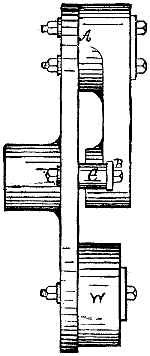
Fig. 886.
If it is intended to plane the back surface of the crank let that be done first as before, and let it be held to the face-plate by bolts and plates as before, while the hole and its radial face at the large end of the crank are turned and finished. In doing this, however, first rough out the radial face, and then rough out the hole, so that if the work alters in form a fine finishing cut on both the radial face and the bore will correct the evil. Then release the crank from the pressure of the holding plates; and it is obvious that however the planed surface may have altered in truth from removing the surface metal, the radial face just turned will be true with the bore turned at the same chucking. Now to chuck the crank to bore the second hole, turn it end for end as in Fig. 886, and bolt the face already turned to the chuck plate (as at a in the figure) with one or more bolts and strap plates. To steady the other end of the crank, and prevent it from moving under the pressure of the cut, take two bolts and plates b, and place a washer between them and the chuck surface as shown at c, then bolt the plates to the chuck plate, so adjusting them that their ends just have contact with the crank when it is set true. In setting it true it may be moved by striking the outer ends of the plates.
In this method of chucking, we have the following advantages:—
1st. If the chuck plate is not true we may place a piece of paper beneath the crank surface a, to correct the error as in the former method, or if this is neglected, the second hole bored will be out of true to an amount answerable to the want of truth in the chuck, and not to twice as much as in the former method.
2nd. Any alteration of form that may take place during the first chucking does not affect the truth of the second chucking as in the other case.
3rd. The crank being suspended during the second chucking, any alteration of form that may accompany the boring of the second hole will be corrected by the finishing cut, hence the crank will be bored with its two holes as axially true as they can be produced in the lathe.
It now remains to explain the uses of the pieces w in Fig. 886, simply weights termed counterbalances bolted to the chuck plate to balance it against the overhanging weight of the crank on one side of the chuck plate. If these weights are omitted the holes in the work will be bored oval, because the centrifugal force generated by the revolution of the work will take up any lost motion there may be between the cone spindle journal and its bearings, or if there be no such lost motion the centrifugal force will in many cases be sufficient to spring the cone spindle.
In selecting these weights it is well to have them as nearly as possible heavy enough to counterbalance the work when placed at the same distance from the lathe centre as the outer end of the work. The proper adjustment of the weight is ascertained by revolving the lathe and letting it slowly come to rest, when, if the outer end, or overhanging end as it termed, of the work comes to rest at the bottom of the circle of revolution on two or three successive trials the weight of the counterbalance must be increased by the addition of another weight, or the weight may be moved farther from the lathe centre.
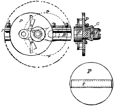
Fig. 887.
To enable a piece of work, such as a crank for example, to have two or more holes bored at one chucking, a class of chuck such as shown in Fig. 887 is sometimes employed. s is a slide in one piece with the hub that screws on the live spindle and standing at a true right angle with the axial line of the cone spindle and made as long as will swing over the lathe bed. It contains a dovetail groove (as shown in the edge view) into which a bar t, running across the back of the face plate p, passes. To cause the bar t to accurately fit the dovetail, notwithstanding any wear of the surfaces, a slip g is introduced, being set up to t by set-screws passing through that side of the dovetailed piece. The work, as the crank c, is bolted to the face plate, and the set-screws on g are eased so that the plate can be moved to set the work true; when true, the set-screws are tightened, and the first hole may be bored. To bore the second hole all that is necessary is to slacken the set-screws on g, move the plate, which will slide in the dovetail groove, and set the work; when the set-screws are again set up tight, the boring may again be proceeded with. In this way both holes may be bored without unclamping the work. The whole truth of the job, before being unclamped from the chuck plate, depends in this case upon the dovetail groove being at a true right angle to the axial line of the lathe cone spindle, it being of no consequence whether the face plate stands true or not. But suppose the removal of the metal to have released strains in the casting or forging, then the clamping plates will have prevented the crank from quite assuming its normal shape after the release of those strains, and the crank, when finished, though true while clamped, will change its form the instant the clamping plates are removed, and the holes bored will in all probability not have their axial lines true one with the other. Another objection is that throwing the chuck plate out of balance on the lathe spindle as well as the crank induces the evils due to the centrifugal motion. This may be offset by increased counterbalancing, of course, but the counterbalancing becomes cumbersome, and is not so easy a matter. For these reasons, chucks of this class are not desirable unless it may be for comparatively small and light work. It is obvious that the dovetail groove may be provided with a screw, and the back of the plate with a nut, so as to move the plate along the groove by revolving the screw. This will assist in adjusting or setting the work, but it will increase the amount of weight requiring to be counterbalanced.
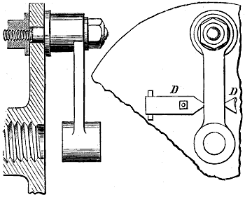
Fig. 888.
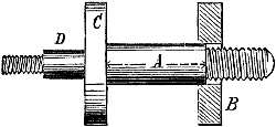
Fig. 889.
When a number of pieces are to be bored with their holes of equal diameters and of the same distance apart, the chucking should be performed as in Figs. 888 and 889; one and the same end of each link should be bored and faced, the links being held by the stem, placed on parallel pieces with plates. A pin such as shown in Fig. 889 should then be provided, its diameter across a being a close sliding fit into the bores of the links; while the length of a should be slightly less than the length of the hole in the link, the part d should be made to accurately fit the hole bored by any suitably sized reamer; a washer b should be provided, and each end should be threaded to receive nuts. There should then be provided in the chuck plate a hole whose distance from the centre of the chuck must exactly equal the distance apart the holes in the links are required to be, and into whose bore the end d of the pin shown in Fig. 889 must drive easily. The pin should be locked in this hole by a nut as shown in Fig. 889. The bored ends of the links may then be placed on the pin and fastened by a nut as in Fig. 888, which will regulate the distance apart of the holes.
It is obvious that the pin may be passed through one of the radial slots in the chuck, and set the required distance from the centre, but in this case the pin would be liable to become moved in its position in the slot.
Side plates to prevent the link from moving should of course be applied as at d, d in the figure.
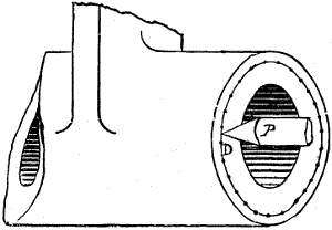
Fig. 890.
The whole process of the second chucking will thus consist of fastening the links on the pin, and setting the free end to the circle made to mark its location. This is done as shown in Fig. 890, which represents the free end of a link, d is the circle marked to set the link by, and p a pointed tool held firmly in the slide rest tool post. The link is obviously set true when the dotted circle on its end face runs true, the pointer merely serving to test the dotted circle.
When, however, one or two links only require to be turned it will not pay to make the pins shown in Fig. 888, especially if the holes of the different links vary in diameter, hence the work must be set by lines.
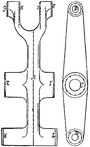
Fig. 891.
In the promiscuous practice of the general workshop, where it may and often does happen that two pieces of work are rarely of the same shape and size, lines whereby to set the work are an absolute necessity, not only to set the work by in chucking it, but also to denote the quantity of metal requiring to be taken off one face in order to bring its distance correct with relation to other faces. An example of this kind is given in Fig. 891, which represents a lever to be bored and faced at the two ends, the radial faces standing at different distances from the centre of the lever stem as denoted by the lines (defined by centre punch dots) e, f, g, h, i, j, k, l. It will be noted that at h, i, f, and e there is but little metal to be taken off, while there is ample at l. Suppose then that the face l were the first one turned, and it was only just trued up, then when f or h were turned there would be no metal to turn, for they may be too near the plane of l already.
The necessity for these lines now being shown, we may proceed to show how they should be located and their services in setting the work. The line a is called the centre line, it passing through the centre of the thickness of the link body on both edges of the link. From it all the other lines, as j, f, l, g, e, k, and h, i, are marked.
The first question that arises in the chucking is, which of the holes b, c, or d, shall be bored first. Now the faces k and l are those that project farthest from the centre line a, hence if the hole at that end be bored and the faces k, l, be turned first, we may bolt those faces against the chuck plate, and thus insure that all three holes shall stand axially true one with the other. If the holes b or c were bored first, l projecting beyond j and f (which are the faces of holes b, c) would prevent the radial face first turned from serving as a guide in the subsequent chuckings, unless a parallel piece were placed between the face and the chuck. In this case, however, there is not only the extra trouble of using the parallel piece, but there would obviously be more liability of error, as from the parallel piece not being dead true and the amount of the error multiplying in the length of the lever, and so on.
The hole d is the one, therefore, to be bored first, the chucking proceeding as follows:—Two parallel pieces of sufficient thickness to keep l clear of the chuck plate should be placed one on each side of the hub e, and bolts and plates placed directly over them. The work must be set so that the line a on each side of the link stands exactly parallel with the face of the chuck, the parallelism being tried at each end of the line, because any error that may be made in setting the work by the full length of the line will have a less effect upon the work than the same amount of error in a shorter length of line. For this reason the centre line should always be marked as long as possible and used to set by, unless there is a longer line running parallel to it and marked on both sides of the link, as would be the case if the dotted line at j and that at l were equidistant from a, in which event they may preferably be used.
The work is set true to the lines by a scribing block, or surface gauge, but as that instrument is more used in setting work with chuck dogs its application will be shown in connection with chucking by dogs; hence to proceed: To set the work true to the line a it may be necessary to place a thickness of paper, a piece of sheet tin, or the equivalent, beneath one of the parallel pieces to bring a parallel with the chuck plate surface. This being done, however, and the circle d being set to run true, the hole may be bored and the radial face l turned off so as to just split the dotted line at l, and this radial face may be used instead of the line a for all subsequent chuckings, so as to avoid the errors that might occur in referring to the line, and from the alterations that might occur in the form of the work from removing the surface metal.
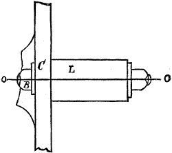
Fig. 892.
Fig. 892 represents a view of the end l as held for the second chucking. c is a section of the chuck plate, and o o represents the line of centres of the lathe, and it is obvious that the radial face of the lever end (which is here represented by l) being used for all but the first chucking, the holes will all stand axially true one with the other, no matter how many chuckings and holes there may be, hence it becomes obvious that the face that will meet the chuck plate is the one that should be turned at the first chucking. It is of no consequence in the case of a single lever whether the pin fits the hole in the end of l, Fig. 892, or not, because the dotted circles at b, c, d in Fig. 891 form the guides whereby to set the holes for distance apart, and any bolt may be used to clamp the work.
It is usual in an example of this kind to turn the stem of the lever to its proper thickness for a short distance from the hubs, so as to have the stem true with the bores, and form a guide whereby to set the lever in the planer or shaper when cutting down the lever stem to size. The rules of chucking and the balance weighting described with reference to chucking a crank, of course also apply to this example.
It will now be observed that in all cases in which work is chucked by bolts and plates, the whole of the faces cannot be turned at one chucking unless the shape of the work is such that it will permit the plates and the bolts to pass or be below the level of the work surface. It will further be noticed that if one face of the work is held against the chuck surface it cannot be turned at the same chucking that the other face is turned at. Now it may be very desirable that a part or the whole of the back face as well as the front one be turned at the same chucking as that at which the hole is bored, so as to have the hole and those two faces true without incurring the errors that might arise from a second chucking. Again, the diameter of the work may be equal to that of the chuck so as to preclude the possibility of using bolts and plates outside of the circumference, and though there be cavities or slots running through the work through which the bolts might be passed, yet the presence of the plates would prevent the face from being turned.
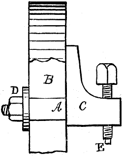
Fig. 893.
To meet these and many other requirements that might be named, chucking by the aid of chucking dogs is resorted to, one of these dogs being shown in Fig. 893. b represents a section of the chuck plate with a piece broken out to show the stem a of the dog, which is squared to prevent its revolving when the nut d, which holds the dog to the chuck plate, is tightened, the holes of the chuck, of course, being square also; e is the set-screw which holds the work, its end at e being turned down below the thread, and the head squared to receive a wrench.
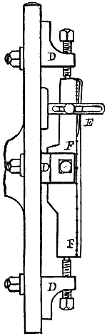
Fig. 894.
Fig. 894 represents an example of chucking by dogs, it being required to face the work off to the dotted line f f. Three of the four dogs used are shown at d, d, d. To set the work the scribing block shown in the figure is employed, the point of the needle being set to the line at any one spot, and the scribing block or surface gauge carried around the work rested with its base against the chuck plate and the needle point tried for coincidence with the line at various points in the work’s circumference. The work is not at first held too firmly by the dogs, so that light blows will suffice to so move the work that the surface gauge needle point applied as shown and at any point around the work will coincide with the line. It will here be observed that using the dogs obviates the necessity for parallel pieces, when the work has projections at the back face as shown in the cut.
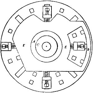
Fig. 895.
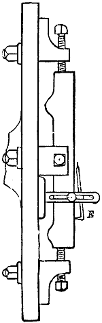
Fig. 896.
Fig. 895 represents another example in chucking by dogs. It is required to surface the whole of the surfaces shown, to bore the hole c and to face a face similar to a, but on the other side or chuck side of the work. Then the work is placed so that its outer face will project beyond the extreme surface of the dogs, and the whole of the operations can be performed at one chucking. It will be observed that in this case the surface of the chuck plate does not automatically serve to guide the work in the chucking, because there is no contact between the two, but the chuck surface can be used as a guide whereby to chuck the work as has just been shown. Or suppose the work to require to be set as true as can be to its exposed face, then the work end of the surface gauge is applied as shown in Fig. 896 at e.
The surface gauge may indeed be dispensed with if the work is sufficiently light that the lathe can be swung around by pulling the chuck plate with the hand, and the work merely requires to be set to run true on its exposed radial face. A pointer held in the slide rest, and applied as in Fig. 890, will denote the setting of the work, which must be tapped until the pointer touches it equally on four equidistant points of the surface; but if it is essential to take as little as possible off the face while truing it up, the tool point should be held stationary, while the work should be so set that the four most distant points (in that circle on the work which is equivalent in radius to the radius to which the tool point stands from the chuck centre) are equidistant as measured by a rule from the tool point. The philosophy of this will be understood from a reference to Fig. 894 and the remarks thereon, this being a parallel case, but applied to a radial face instead of to a circumference.
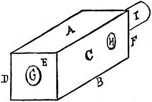
Fig. 897.
Now suppose we have the piece of work shown in Fig. 897, which requires to have its surfaces a and b parallel and at a right angle to c and d, the end faces e and f parallel to each other, and at a right angle to both a, b, c, and d, the hole at g is to be axially true with the surfaces a, b, c, and d, as well as with the pin at i, and the hole at h at a dead right angle to that at g.
We may put a plug in g and turn up the surfaces e and f, and turn the pin i; this, however, would leave the hole g unbored, whereas it should be bored when the surface e is turned; again, after these surfaces are turned they are of no advantage as guides in the subsequent chuckings.
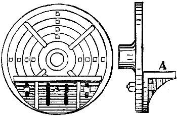
Fig. 898.
We may grip the surfaces e and f in a jaw chuck to turn the surfaces a, b, c and d, but depending upon the face jaws of the dogs to set the work surface true by; but this would not be apt to produce true work on account of the spring of the jaws, as explained in the remarks upon jaw chucks; furthermore, the work, supposing it to be a foot long, could not be held in a dog chuck sufficiently firmly to enable the turning of the end face e or the pin i, and this brings us to that most excellent adjunct to a general chucking lathe, the angle plate shown in Fig. 898.
It is simply a plate of the form shown in the figure, having two flat and true surfaces, one at a right angle to the other; one of these surfaces bolts to the chuck plate, while the other is to fasten the work on. The slots shown are to pass the bolts through to fasten the angle plate to the chuck plate, and the work surface of the plate contains similar slots and holes to receive the bolts used to fasten the work.
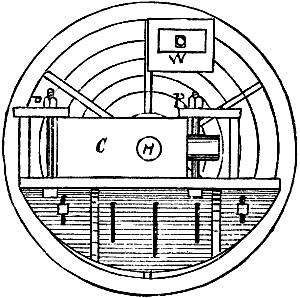
Fig. 899.
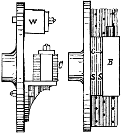
Fig. 900.
Suppose, then, we fasten the piece of work to the angle plate as shown in Fig. 899, and face off the surface c, and bore the hole h, the work being set true with its surface, or to a line, by the aid of a surface gauge, as may be required. We then turn surface c down to meet the surface of the angle plate, fasten it to the same with bolts and plates and setting it as before, and on turning its surface a we shall have the two surfaces a and c at a right angle to one another. We then turn the surface a down upon the angle plate and bolt it again as before. But we have now to set it so that the surface c shall be quite parallel with the surface of the chuck plate. This we may do by placing one or more parallel strips behind it, as at s s, in the plan view, Fig. 900, setting the work so that it binds the parallel strips tight against the chuck plate along their full lengths; or we may measure the distance of c from the chuck plate surface with a pair of inside calipers; or we may turn the bent end of a surface-gauge needle outwards and gauge the work as shown in the plan view, trying the work all along. On turning the surface d, Fig. 897, we shall have three of the surfaces done at right angles and with c and d parallel.
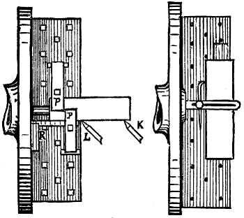
Fig. 901.
It is obvious that the surface d may be turned down on the angle plate and bolted as before, the surface a being set parallel to the chuck plate surface as before, and all four of these surfaces will be finished true as required. Next come the two end surfaces and the pin i. For f and the pin i we chuck the work on the angle plate, as shown in the plan view, Fig. 901, p, p representing the clamping-plates. The angle plate will here again serve to hold the work true one way, and all we have to do to set it true the other way is to fasten a pointer in the tool post and bring it up to just touch the corners of the work at the outer end, as at k. Now run the carriage up so as to bring the pointer to position l, and when the work is so set that all four corners just touch the pointer, tried in their two positions, without touching the cross-feed screw, the work is true, and the end surface e and hole g may be turned; e will then be at a true right angle to the four faces, a, b, c, d, while g will be axially true with them.
We may, instead of using the pointer at k and l, or in addition to so using it, apply a square against the chuck plate and bring the blade against the work, as shown at r.
We have now to turn the pin i and end face, and to do this we simply reverse the work, end for end, and bolt it as before. But we may now employ the trued surface e as an aid in setting by causing it to abut against the chuck plate surface, and, as an aid to finding that it abuts fair, we may put two strips of the same piece of paper behind it, one on each side of the square, and, after the work is bolted, see that both are held firm; but it is necessary to test with the pointer as before, as well as with the square.
It is obvious that the angle plate requires counterbalancing, which is done by means of the weight w. (Fig. 900).
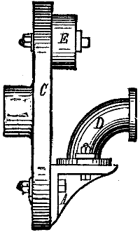
Fig. 902.
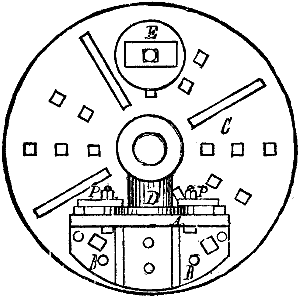
Fig. 903.
An excellent example of angle plate chucking is furnished in a pipe bend requiring both flanges to be turned up. The method of chucking is shown in Figs. 902 and 903, the flanges being simply bolted to the angle plate. The work may be set true to the body of the bend close to the neck of the flange or by the circumference of the flange. The face of the flange will be held true one way by the face on the angle plate, but must be set true the other way. The truest flange should be the one first bolted to the angle plate.
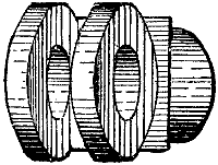
Fig. 904.
A common but good example of angle plate chucking is shown in Fig. 904, which represents a cross head requiring to have its two holes bored one at a right angle to the other, the jaws faced inside and outside, and the hub or boss turned.
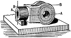
Fig. 905.
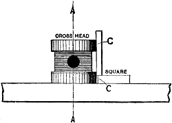
Fig. 906.
It would be proper to mark the cross-head out by lines, giving dotted circles to set the work by, and dotted lines to give the thickness of the jaws. In thus marking out two centre lines a a and b b in Fig. 905 would be used to locate the centres of the holes; and the thickness of the jaws would be marked from the line b b. In marking these lines the cross head should be rested upon a table or plate as in Fig. 905, and the line a a should be made with the jaws of the cross head lying flat on the table, that is without the interposition of any packing or paper between them and the plate, so that the edges of the jaws on that side will be true with the line a a, and will therefore serve to apply a square against when chucking to bore the hole through the jaws. If the jaw edges are not sufficiently true to permit of their lying on the table, they should be made so by filing a flat place on them, so that when a square is applied to them as in Fig. 906, the edges c, c will be parallel with the axis a a of the holes in the chucks or jaws. The first chucking should be as in Fig. 907, the cross head being bolted to an angle plate set true by the circle on the end face of its hub d, and a square being applied to the centre line a, as in Fig. 908, and to the dotted lines on the jaws as shown in Fig. 909. A balance weight w, Fig. 907, is necessary to counterbalance the weight of the angle plate.
VOL. I. EXAMPLES IN ANGLE‑PLATE CHUCKING. PLATE XII.
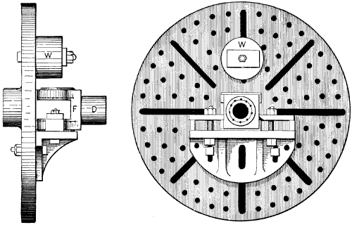
Fig. 907.
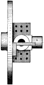
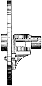
Fig. 908. Fig. 909.
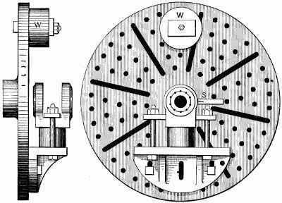
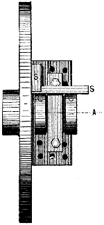
Fig. 910. Fig. 911.
The second chucking to bore the cheeks and face them inside and out to the required thickness would be as in Fig. 910, a single plate and two bolts being used to hold the cross head to the angle plate. To set the cross head true in one direction, the outer circle shown marked upon the face of the cheek is used.
It remains to so set the face of the cheeks that the hole through them shall be central with that already bored through the hub d and all that is necessary to accomplish this is to set the edge true as shown in the top view in Fig. 911, in which s is a square rested against the face of the chuck and applied to the edges of the cheeks, these edges being those that were rested on the plate when marking the line a a in Fig. 905, or that were filed square if it was found necessary as already mentioned.
The inside faces of the cheeks are turned to the dotted lines shown in Fig. 909, and the outside faces being turned each to the proper thickness measured from the outside ones, the job will be complete and true in every direction.
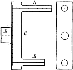
Fig. 912.
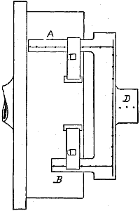
Fig. 913.
An excellent example of angle plate chucking is shown in Fig. 912—the actual dimension of the piece, measuring, say, 24 inches in length. It is required to have the cylindrical stems a, b turned parallel to each other, of equal diameters, equidistant from the central hole c, and true with the hub d. A large piece of work of this kind would be marked off with lines defined by centre-punch dots, as shown. The ends of a, b, d would require dotted circles to set them by. Now, in all work of this kind it is advisable to turn that surface first that will afford the greatest length of finished surface, to serve as a guide for the subsequent chucking, which in this case is the hub d, and the face on that side as denoted by the dotted line which has to be cut to that line. The method of chucking would, for this purpose, be as in Fig. 913.
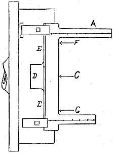
Fig. 914.
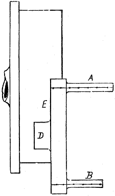
Fig. 915.
The second chucking would be as in Fig. 914 to bore the hole at c, while, at the same time, the surface from f to g may be turned. Either inside calipers or a surface gauge may be employed to set e e parallel to the chuck plate surface. It is supposed that the location c is defined by a dotted circle, by which the work may be set for concentricity, as should be the case. At the next chucking it will simply be necessary to move the work on the angle plate to the position shown in Fig. 915, setting the circle on the end of a to run true, and the surface e parallel to the chuck surface as before. The third chucking is made by simply moving the work on the angle plate again, and setting as in the last instance.