Volume 2 — Chapter XXII.—MILLING MACHINERY AND MILLING TOOLS.
Reading edition
The Milling Machine.—The advantages of the milling machine lie first in its capacity to produce work as true and uniform as the wear of cutting edges will permit (which is of especial value in work having other than one continuous plane surface); second, in the number of cutting edges its tools will utilize in one tool or cutter; and third, in its adaptability to a very wide range of work, and in the fact that when the work and the cutters are once set the operator may turn out the best quality of work without requiring to be a skilled machinist.
The extended use of the milling machine, which is an especial feature of modern machine shop practice, is due, in a very large degree, to the solid emery wheel, which provides a simple method of sharpening the cutters without requiring them to be annealed and rehardened, it being found that annealing and rehardening reduces the cutting qualifications of the steel, and also impairs the truth of the cutting edges by reason of the warping or distortion that accompanies the hardening process. Rotary cutters are somewhat costly to make, but this is more than compensated for in the uniformity of their action, since in the case of the cutter the expense is merely that involved in forming the cutting edges with exactitude to shape; once shaped the cutter will produce a great quantity of work uniform in shape, whereas in the absence of such cutters each piece of work would require, to bring it to precise form, as much precision and skill as is required in shaping the cutter.
If a piece of work is shaped in a planing machine, the different steps, curves, or members must be cut or acted upon by the tool separately, and the dimensions must be measured individually, giving increased liability to error of measurement, and requiring a fine adjustment of the cutting tool for each step or member. Furthermore, neither a planing machine or any other machine tool can have in simultaneous cutting operation so great a length of cutting edge as is possible with a rotary cutter.
Again, in the planing machine each cut requires to be set individually, and cannot be so accurately gauged for its depth, whereas with a rotary cutter an error in this respect is impossible, because the diameters of the various steps on the cutter determine the depth of the respective cuts or steps in the work.
In a milling machine the cut is carried continuously from its commencement to its end, whereas in a shaping or planing machine the tool does not usually cut during the back or return stroke. In either of these machines, therefore, the operator’s skill is required as much in measuring the work, setting the tools feeds, &c., as in shaping the tools, whereas in the milling machine all the skill required lies in the chucking and adjustment of the work to the cutter, rather than in operating the machine, which may therefore be operated by comparatively unskilled labor.
The multiplicity of cutting edges on a rotary cutter so increases its durability, and the intervals at which it must be sharpened are so prolonged, that, with the aid of the present improved cutter grinding machines, one tool maker can make and keep in order the cutters for many machines.
The speed at which milling cutters are run varies very widely in the practice in different workshops. Thus upon cast iron, cutting speeds of 15 circumferential feet per minute will be employed upon the same class of work that in another shop would be done at a cutting speed of as high as fifty feet per minute. With the quick speeds, however, lighter feeds are employed. As the teeth of milling cutters are in cutting action throughout but a small portion of a revolution, they have ample time to cool, and may be freely supplied with oil, which enables them to be used at a higher rate of cutting speed than would otherwise be the case. Yet another element of importance in this connection is that when the cut is once started on a plain cutter, the cutting edges do not meet the surface skin of the metal, this skin always being hard and destructive to the cutting edges.
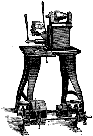
Fig. 1878.
The simplest form in which the milling machine appears is termed the hand milling machine, and an example of this is shown in Fig. 1878. This machine consists of a head carrying a live spindle which drives the cutting tools, which latter are called cutters or mills. The front of the head is provided with a vertical slideway for the knee or bracket that carries an upper compound slide upon which the work-holding devices or chucks are held. The work is fed to the revolving cutter by the two levers shown, the end one of which is for the vertical and the other for the horizontal motion, which is in a direction at a right angle to the live spindle axis.
In other forms of the hand milling machine the live spindle is capable of end motion by a lever.
In Fig. 1878a is shown Messrs. Brown and Sharpe’s plain milling machine, or in other words a milling machine having but one feed motion, and therefore suitable for such work only as may be performed by feeding the work in a straight line under the cutter, the line of feed motion being at a right angle to the axis of the cutter spindle.
Machines of this class are capable of taking heavy cuts because the construction admits of great rigidity of the parts, there being but one slideway, and therefore but one place in the machine in which the rigidity is impaired by the necessity for a sliding surface.
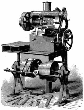
Fig. 1878a.
The construction of this machine is as follows: The head a which carries the cutter spindle is pivoted at c to a stiff and solid projection on the frame f, and means are provided to solidly clamp the two together.
A bracket b supports the outer end of the head; at its upper end b is split so that by means of a bolt it may firmly clamp the cylindrical end of a, which carries the dead centre piece d. The two lower ends of b are bolted to the frame f.
The work table t is gibbed to slideways in f, and is provided with suitable automatic feed and stop motion, and of course with a hand feed also.
To adjust the height of the cutter, the lower ends of b are released from f and the head a is swung on its centre c.
It is obvious that a machine of this class is suitable for cases where a large quantity of work of one kind is to be done and frequent changes of the adjustments are not required, and that for such work the solidity of the construction and the convenience of having all the handles employed in operating the machine accessible from one position are desirable elements obtained by a very simple construction.
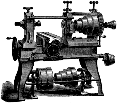
Fig. 1879.
Fig. 1879 represents Pratt & Whitney’s power milling machine. The cone and live spindle are here carried in boxes carried in vertical slideways in the headstock, so as to be adjustable in height from the work table, and is provided with a footstock for supporting the outer end of the live spindle, which is necessary in all heavy milling. The carriage is adjustable along the bed, being operated by a screw whose operating hand wheel is shown at the left-hand end of the bed.
The automatic feed is obtained as follows: The large gear on the right of the main driving cone operates a pinion driving a small four-step cone connected by belt to the cone below, which, through the medium of a pair of spur-gears, drives the feed rod, on which is seen a long worm engaging a worm-wheel which drives the feed screw. A suitable stop motion is provided.
What is termed a universal milling machine is one possessing the capacity to cut spiral grooves on either taper or parallel work, and is capable of cutting the teeth of spur and bevel-gears or similar work other than that which can be held in an ordinary vice. These features may be given to a machine by devices forming virtually an integral part of the machine, or by providing the machine with separate devices which are attachable to the work table.
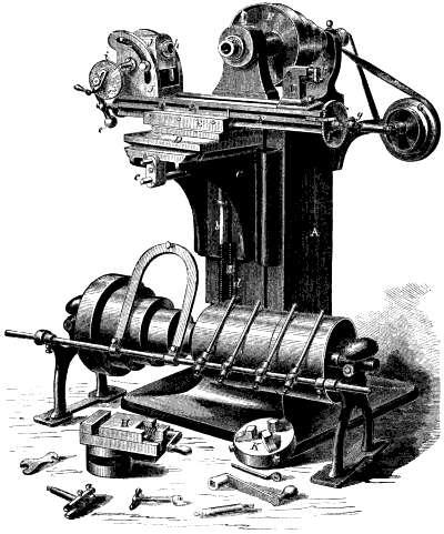
Fig. 1880.
In Fig. 1880 is represented a small size universal milling machine, in which a is the frame that affords journal bearing to the live spindle, in the coned mouth a of which the mandrel carrying the rotary cutter is fitted, means being afforded for taking up the wear of the live spindle journal and bearings. b is the cone pulley for driving a. Upon the front face of a is a vertical slide upon which may be traversed the knee or table c, which by being raised, regulates the depth to which the cutters enter the work. To operate c the vertical screw b is provided, it being operated (by bevel-gears) from a horizontal shaft whose handle end is shown at c.
The nut for elevating screw b is formed by a projecting lug from or on the main frame a. To enable c to be raised to a definite height so that the cutters shall enter successive pieces of work to an equal depth, a stop motion is provided in the rod d, which passes through a plain hole in the lug on a that forms a nut for b. Rod d is threaded and is provided with a nut and chuck nut whose location on the length of the rod determines the height to which c can be raised, which ceases when the faces of the nuts meet the face of the projecting lug.
The upper surface of c is provided with a slide on which is a slider d, which, by means of a feed screw whose handle end is shown at e, may be traversed in a line parallel to the axial line of the live spindle or arbor, as it is more often termed, this motion being employed to set the width of the work in the necessary position with relation to the rotary cutters. To d is attached e, which is pivoted at its centre so as to be capable of swinging horizontally, means being provided to fasten it to d in its adjusted position. This is necessary to enable the line of traverse of the work to be at other than a right angle to the axial line of the cutter spindle when such is desired, as in the case of cutting spirals; e serves as a guide to the carriage f, the latter being operated endwise by means of a screw whose handle is shown at e′′, the nut being attached to e, handle e′′ being to traverse e by hand. To feed f automatically gear-wheel f is attached to the other end of the same screw, this automatic feed being actuated as follows:—
At the rear end of the live spindle is a three-stepped cone pulley attached by belt to cone pulley g, which connects by rod to and drives gear f. The construction of the rod is so designed as to transmit the rotary motion from g to f without requiring any adjustment of parts when c is raised or lowered or f traversed back or forth, which is accomplished as follows:—
At g g are two universal joints attached respectively to g and f, and to two shafts which are telescoped one within the other. The inner rod is splined to receive a feather in the outer. The rotary motion is communicated from g to the universal joint, through that joint to the outer or enveloping shaft which drives the inner shaft, the latter driving a universal joint which drives f, the inner shaft passing freely within the outer or sliding out from it (while the rotary motion is continuing) to suit the varying distance from and position of f with relation to g. This automatic feed motion may be adjusted to cease at any point in the traverse of e by a stop and lever provided for the purpose, so that if an attendant operates more than one machine, or if the feed require to be carried a definite distance, it will stop automatically when that point has been reached.
The carriage f may carry various chucks or attachments to suit the nature of the work. As shown in the cut it carries a tailblock i and head j, both fitting into a way provided in f so that they will be in line one with the other at whatever part in the length of f they may be set or fixed. Both i and j carry centres between which the work may be held, as in the case of lathe work. Part j is pivoted to j so that it may be set at an angle if required, thus setting the centre, which fits in the hole at h, above the level of that in i, as may be necessary in milling taper work, the raising of j answering to the setting over of the tailstock of a lathe for taper turning.
To enable the accurate milling of a polygon, the spindle h may be rotated through any given portion of a circle by means of the index wheel at i, it being obvious that if a piece of work be traversed beneath the cutter, and h be rotated a certain portion of a circle after each traverse, the work will be cut to a polygon having a number of sides answering to the portion of a circle through which h is rotated after each traverse. Means are also provided to rotate h while f is traversing beneath the cutter; hence when these two feed motions act simultaneously the path of the work beneath the cutter is a spiral, and the action of the cutter in the work is therefore spiral; hence spiral grooves may be cut or spiral projections left on the work, as may be determined by the shape of the cutters. k is a chuck that may be connected to h to drive the work, and h a work-holding vice, that may be used instead upon f in place of heads i j.
The countershaft shown at the foot of the machine has two loose pulleys and a tight one between them, this being necessary because, in cutting spiral work, the work must rotate while on the back traverse as well as on the forward one, hence a crossed as well as an open belt is necessary.
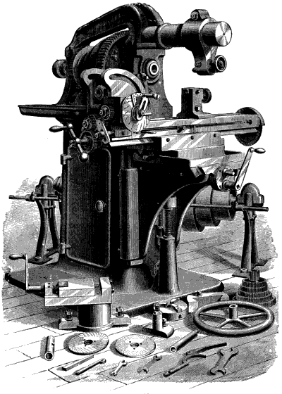
Fig. 1881.
Fig. 1881 represents a large Brown & Sharp universal milling machine, in which the cone spindle is provided with back gear, and a supporting arm is also provided for the outer end of the cutter arbor. The feed motions for this machine correspond to those already described for the smaller one, Fig. 1880, the construction of the important parts being shown in the following figures.
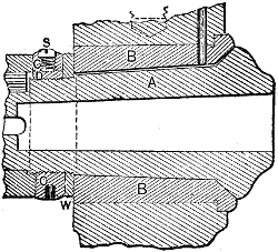
Fig. 1882.
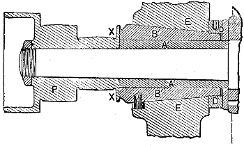
Fig. 1883.
The construction of the bearings for the cutter driving spindle of the machine is as in Figs. 1882 and 1883. a is the spindle having a double cone to fit corresponding cones in the sleeve b, the fit of one to the other being adjusted by means of the nut c, which is threaded upon a. The mouth of a is coned to receive the arbors or mandrels for driving the mills or cutters. At the back bearing, Fig. 1883, the journal a′, and bore of the sleeve b′, is parallel, this sleeve being split at the top so that when it is (by means of nut d) drawn within the head e its coned exterior will cause it to close to a proper fit upon a′, by which means the wear of the parts may be taken up as they become perceptible.
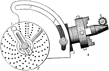
Fig. 1884.
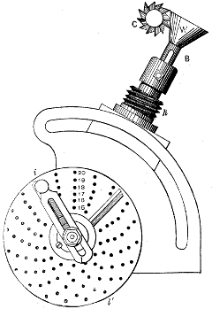
Fig. 1885.
The head j, Fig. 1880, is used (in connection with the foot block i) to suspend or hold work by or between centres, its centre fitting into the spindle at h, which is capable of being revolved continuously (to enable the cutting of spirals), by means of change gears, and intermittently through a given part of a circle by means of the index wheel i. The block j carrying the spindle is also capable of elevation for conical or taper work, two examples of such uses being shown in Figs. 1884 and 1885, in which c is the cutter and w the work.
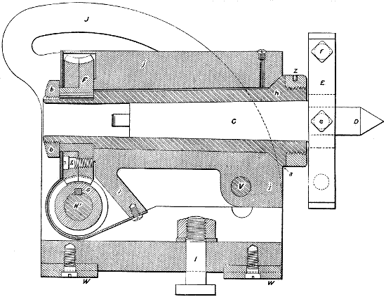
Fig. 1886.
Fig. 1886 is a sectional view in a vertical plane through the centre of the head, and showing the construction of the spindle and the means of elevating the block j; h is the spindle having journal bearing in j, and secured from end motion by the cone at a and the nut b; its bore is coned at the front end to receive the arbor c carrying the centre d, upon which is the piece e for driving the work dog, which is secured within e by the set-screw f. Fast upon spindle h is a worm-wheel f made in two halves, which are secured together by the screws g. At g is the worm-wheel (for driving f) fast upon the shaft h′.
It is obvious that the block j may be raised at its centre end upon h as a centre of motion, the worm f simply moving around upon g. At v is a bolt to lock j to j, and thus secure it in its adjusted position. w w are lugs or blocks fitting into the slot in the work table, and serving to secure the head, being in line with the foot block (shown at 1 in Fig. 1880). A sleeve z is used to cover the thread and protect it when a chuck is not used.
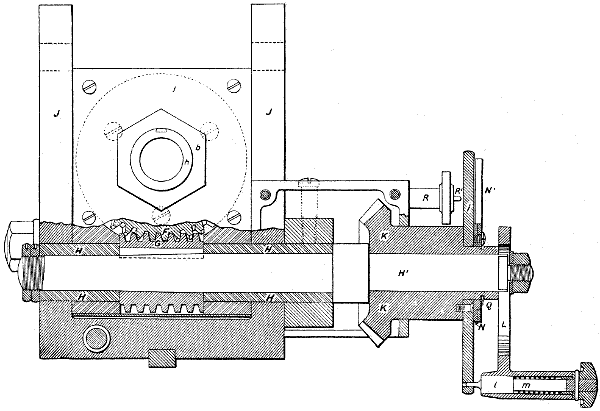
Fig. 1887.
Fig. 1887 is an end view partly in section to show the construction of the worm shaft and the index plate. h is a sleeve upon which j pivots, and h′ the worm shaft, which may be revolved by hand by the lever l, or automatically by means of the bevel-gear k, which connects with the train of change gears; these change gears being thrown out of operation when gear k (and therefore h) is not required to revolve automatically nor continuously. l is an arm for carrying the index pin l for the index plate i. The pin l is adjustable for radius from the centre of h (so as to come opposite to the necessary circle of holes on the plate i), the arm l being slotted to permit of this adjustment, and being secured in its adjusted position by the nut on the end of h′. Pin l is pushed into the index holes by means of the spiral spring coiled around l at m, which permits l to be withdrawn from i under an end pressure, but pushes it into i when that pressure is released. To indicate the amount of rotation of i, without counting the number of holes, a sector n n′ is employed, it having two arms adjustable for their widths apart so as to embrace any given number of holes on the required circle. At r′ is a pin which is pulled forward and into holes provided in the plate i to prevent its turning when using the lever l. n and n′ are held to the face of i by the friction of the spring q. A face view of index plate i is shown in Fig. 1888, the lever l, Fig. 1887, being removed to expose n and n′.
The surface of the plate is provided with rings of holes marked respectively 20, 19, 18, &c., the holes in each ring or circle being equidistantly spaced.
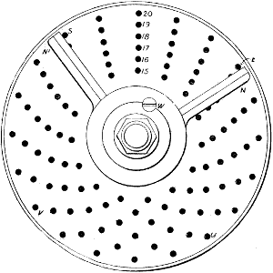
Fig. 1888.
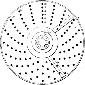
Fig. 1888a.
The sector arms n and n′ may be opened apart or closed together so as to embrace any required number of holes in either of the circles. As shown in the cut they embrace one quarter of the circle of 20, there being five divisions between the holes s and t. The screw w secures them in their adjustment apart. Suppose that pin l (Fig. 1887), is in s, and arm n′ is moved up against it, the arm n leaves t open, and indicates that t is the next hole for pin l, which is withdrawn from s, and lever l (Fig. 1887) is moved around until the pin will enter t, and the sector is then moved into the position shown in Fig. 1888a, indicating that hole u is the next one for the pin. This obviates the necessity of counting the holes, and prevents liability to error in the counting. Three of these index plates are provided, each having different numbers of holes in the circles, and in the following tables are given those specially prepared for use in cutting the teeth of gear-wheels:
No. of teeth. Index circle. No. of turns of index. No. of teeth. Index circle. No. of turns of index.
2 ANY 20 80 20 10⁄20
3 39 13 13⁄39 82 41 20⁄41
4 ANY 10 84 21 10⁄21
5 „ 8 85 17 8⁄17
6 39 6 26⁄39 86 43 20⁄43
7 49 5 35⁄49 88 33 15⁄33
8 ANY 5 90 27 12⁄27
9 27 4 12⁄27 92 23 10⁄23
10 ANY 4 94 47 20⁄47
11 33 3 21⁄33 95 19 8⁄19
12 39 3 13⁄39 98 49 20⁄49
13 39 3 3⁄39 100 20 8⁄20
14 49 2 42⁄49 104 39 15⁄39
15 39 2 26⁄39 108 27 10⁄27
16 20 2 10⁄20 110 33 12⁄33
17 17 2 6⁄17 115 23 8⁄23
18 27 2 6⁄27 116 29 10⁄29
19 19 2 2⁄19 120 39 13⁄39
20 ANY 2 124 31 10⁄31
21 21 1 19⁄21 128 16 6⁄16
22 33 1 27⁄37 130 39 12⁄39
23 23 1 17⁄23 132 33 10⁄33
24 39 1 26⁄39 135 27 8⁄27
25 20 1 12⁄20 136 17 5⁄17
26 39 1 21⁄39 140 49 14⁄49
27 27 1 13⁄27 144 18 5⁄18
28 49 1 21⁄49 145 29 8⁄29
29 29 1 11⁄29 148 37 10⁄37
30 39 1 13⁄39 150 15 4⁄15
31 31 1 9⁄31 152 19 5⁄19
32 20 1 5⁄20 155 31 8⁄31
33 33 1 7⁄33 156 39 10⁄39
34 17 1 3⁄17 160 20 5⁄20
35 49 1 7⁄49 164 41 10⁄41
36 27 1 3⁄27 165 33 8⁄33
37 37 1 3⁄37 168 21 5⁄21
38 19 1 1⁄19 170 17 4⁄17
39 39 1 1⁄39 172 43 10⁄43
40 ANY 1 180 27 6⁄27
41 41 40⁄41 184 23 5⁄23
42 21 20⁄21 185 37 8⁄37
43 43 40⁄43 188 47 10⁄47
44 33 30⁄33 190 19 4⁄19
45 27 24⁄27 195 39 8⁄39
46 23 20⁄23 196 49 10⁄49
47 47 04⁄47 200 20 4⁄20
48 18 15⁄18 205 41 8⁄41
49 49 20⁄49 210 21 4⁄21
50 20 16⁄20 215 43 8⁄43
52 39 30⁄39 216 27 6⁄27
54 27 20⁄27 220 33 6⁄33
55 33 24⁄33 230 23 4⁄23
56 49 35⁄49 232 29 5⁄29
58 29 20⁄29 235 47 8⁄47
60 39 26⁄39 240 18 3⁄18
62 31 20⁄31 245 49 8⁄49
64 16 10⁄16 248 31 5⁄31
65 39 24⁄39 260 39 6⁄39
66 33 20⁄33 264 33 5⁄33
68 17 10⁄17 270 27 4⁄27
70 49 28⁄49 280 49 7⁄49
72 27 15⁄27 290 29 4⁄29
74 37 20⁄37 296 37 5⁄37
75 15 8⁄15 300 15 2⁄15
76 19 10⁄19 310 31 4⁄31
78 39 20⁄39 312 39 5⁄39
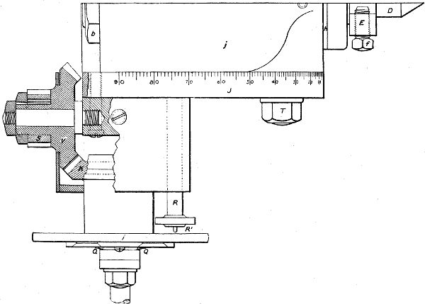
Fig. 1889.
A plan view of one-half of the head is shown in Fig. 1889, the edge of j being graduated for a guide in elevating the head at an angle, at v is the bevel-gear for driving k, and at s is a pinion receiving motion from the change gears.
Large
image
(63 kB).
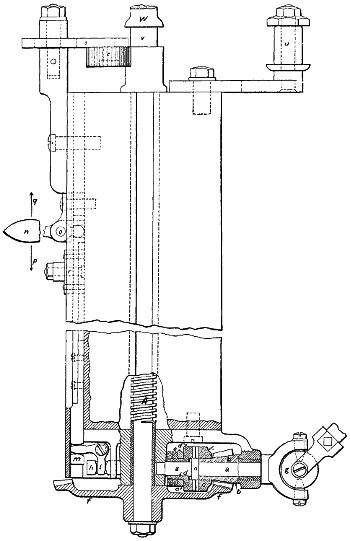
Fig. 1890.
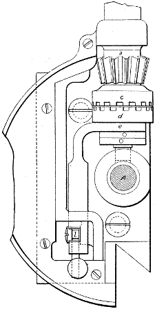
Fig. 1891.
The feed motions for the traversing table (f, Fig. 1880) is shown in Figs. 1889, 1890, and 1891, g represents the universal joint rotating continuously the spindle a, which provides journal bearing to bevel pinion b and the clutch c, these two being fixed together; d is a clutch which rotates with a, but is capable of a certain amount of end motion on or along a to enable it to engage or disengage with its mate c. When d engages with c the rotary motion of a is transmitted through d, c, b, to f, which actuates the feed screw a, while when d is disengaged from c, it rotates, leaving c b f idle. d is operated to engage with or disengage from c, its hub is enveloped by the fork e, which is attached to rod h, which is provided with a recess to receive one end of the bell crank l, the other end of which lies in a recess in the rod m, to the end of which is connected the lever handle n, which is pivoted at o; hence operating n laterally as denoted by the arrows, throws d in or out of gear with c, according to the direction of motion, direction p being that to throw it out of, and q to throw it into gear or engagement. At r is a stop that can be fixed at any adjusted position or desired location along the bed upon which the feed table or carriage (f, Fig. 1880) slides, so that when that carriage is being self-actuated it will traverse until the inner end of n meets the stop, whereupon the stop will move n and thereby disengage d from c, causing the automatic feed to cease. All that is necessary, therefore, is to set r in such a position along the bed that it will operate n when the milling cutter has operated to the required distance along or over the work; s is the stud arm that carries wheel t to engage with and drive the pinions shown in Fig. 1889, and u is the stud for carrying the wheels for giving the required changes of rotation to k, Fig. 1889, the wheels on u receiving motion from a gear placed at the seat v on the feed screw a. The stud arm s being slotted, can be moved forward, transmitting motion from the change wheels on u to wheel s, Fig. 1890, causing the automatic spiral feed to actuate; or by moving s outwards, this feed is thrown out of action, and either the hand feed of handle w or the self-acting feed traverse may be employed.
Thus the hand, and all the automatic feed motions are driven from the feed screw a, and each of the automatic feed motions may be started or stopped by operating the lever n, while the stop r causes each of them to cease when the work has traversed to the required distance beneath the milling cutter.
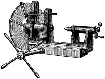
Fig. 1892.
Fig. 1892 represents an attachment to this machine to facilitate cutting the teeth of gears, which it does because its index plate operates the work-holding mandrel direct, and may, therefore, be set quicker. The base bolts to the machine table and the index head and tailblock are traversed in the base by means of the four-levered handle shown.
Figs. from 1893 to 1899 represent a universal milling machine. This machine is so constructed that all the features essential to a universal milling machine are obtained by means of attachments (each complete in itself) which may be removed, leaving the work table clear, and, therefore, serviceable for large work, or work which may be more conveniently held without the use of attachments.
The T-slots in the table are furnished to standard size, and are at right angles, so that the attachments will be held exactly parallel with, or at a right angle, as the case may be, to the live spindle of the machine; hence the machine will accomplish all the varied results required in the tool room or for machine work generally.
Thus for the cutting of spirals, a fixture capable of originating any spiral right or left hand, from 2 inches to 6 feet pitch, is provided. Two bolts secure it to the machine table, and when the job is finished it is removed. Similarly for the cutting of cams, an attachment fastened to the work table by three bolts is used, which cuts either cylinder or face cams of considerable size, and as conveniently as a machine built solely for cam cutting. A gear-cutting device is also applied in the same manner, as well as plain or universal work-holding centres.
VOL. II. EXAMPLE OF MILLING MACHINE. PLATE I.
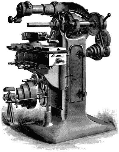
Fig. 1893.
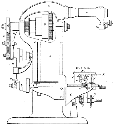
Fig. 1894.
The essential features of the machine are a standard a, Fig. 1894, with spreading base, carrying upon its top a driving cone b, which is fully back-geared like an engine lathe. The driving cone operates also the feed mechanism. Above the driving cone is an arch c, in which is inserted an arm d for supporting the outer end of the mill arbor when used for heavy work. Upon the face or front of the standard slides a knee e, which in its turn supports a carriage f, which traverses crosswise upon it and carries above it the work table, which is provided with an automatic feed at right angles with the movement of the carriage. These three movements, vertical, cross, and longitudinal, cover all that is usually required in a universal milling machine.
Coming to details we start with the spindle or arbor, the front end of which runs in bearings of bronze. These are made in two parts, tapering upon the outside and straight upon the inside, a corresponding taper hole to receive the spindle bearings being bored in the solid iron of the standard. A check nut upon each end of the bushing or bearing abuts against the end faces of the standard bearing, and by drawing the bushing or bearing through the taper hole in the standard, produces the exact required closeness of fit between the spindle journal and its bearing bore, and thus compensates for the wear of either the spindle journal or its bearing or bushing bore, the front check nut also providing a dust cap.
The back journal of the spindle runs in a bushing of considerable length. Upon the back end of the spindle is secured a train of feed gears g, the lower of which is upon a shaft that on its other end carries the first feed cone h. The corresponding feed cone i is fixed to the longer shaft j, carrying a worm (or tangent screw) k, which engages with the worm-gear l connected directly with the feed screw, for the longitudinal motion of the work table.
This whole feed work is shown fully in outline in Fig. 1894. The arm m that supports the two lower feed gears pivots upon the outboard end of the back bushing, hence its centre coincides with that of the spindle. At its lower end a projection inwards forms a hub upon which a second lug or arm n is pivoted. The lower end of this arm is bored out to receive the threaded end of a lug o with the bearing of the second feed cone i. This threaded end carries a milled or hand nut p, so that to tighten or loosen the feed belt a turn of the nut is sufficient, the effect being to increase or diminish the distance between the feed cones h and i. The front end of the feed rod is supported in a drop box q, and is splined to allow the worm k to travel upon it. It will be seen, therefore, that the feed mechanism is undisturbed either by the vertical movement of the knee, or the cross motion of the carriage, or the longitudinal feed of the table. The feed gears are covered with a shield r, a part of which is shown broken away. The knee with its appendages is actuated vertically by means of a crank connected with bevel gearing at s, which moves a perpendicular screw t under the centre of the knee. Rotating with this crank-shaft is a finger u held by friction. This finger is in close proximity to a dial v graduated to thousandths of an inch, and as one revolution of the finger indicates 1⁄8 of an inch of elevation to the knee e, the ordinary subdivisions of an inch are obtained either with or without an inner circle of graduations on the dial. A similar dial upon the cross feed motion (not shown in the engraving) is also put on, which likewise reads to thousandths of an inch.
The feed of the work table is accomplished by means of a screw whose thread is in shape a half V and does not bear upon the bottom of the thread in the feed nut, which is in halves, with provision for closing up to compensate for wear, while check nuts on one end of the feed screw take up all end play.
The automatic feed is self-stopping (so as to enable one attendant to operate several machines) by means of the following construction:—
In the general view, Fig. 1893, there is seen a stop that is secured in the required position in the T-groove shown at x in the outline view, Fig. 1894, and when this stop meets the bell crank y it unlatches it from a lug which is on the drop box q, Fig. 1893, hence this box falls and with it that end of the worm shaft j, throwing it out of gear with the worm-wheel l, and therefore stopping the feed.
The attachments giving to this machine its universal qualifications are as follows:—
The rotary vice is shown on the work table in the general view, Fig. 1893; and requires but little description. Upon the underside of the base is a circular projection having beneath it a projection fitting into the T-slots in the work table. Two segmental slots in the base admit of a rotary movement of the vice within a range of 90°, and it is held to the table by two bolts. The crank or handle of the vice is made more convenient by means of two square holes that fit the end of the screw that actuates the movable jaw. Using the central hole allows the handle to clear the work table, but when the vice jaws need to be closed with considerable force the handle is shifted to the end or outer hole, thus doubling the leverage.
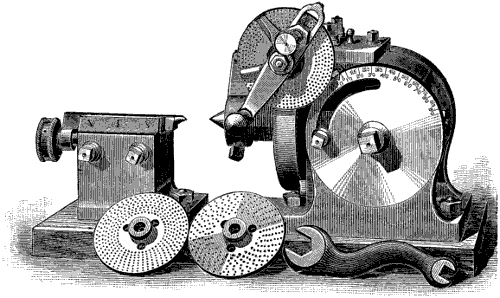
Fig. 1895.
The Universal Head and Back Centre.—This tool is used for making milling cutters either straight or angular, cutting small gears either spur or bevel, fluting taps or reamers, finishing nuts or bolt-heads, and a multitude of other jobs too numerous to particularise. The head consists, as seen in Fig. 1895, of a swinging block mounted centrally between the two upright sides or jaws of a base, and is clamped in any position by a set-screw on either side. The face of one side or jaw is laid out in degrees, and a finger or pointer on the block indicates its angle of elevation. On the front end of the spindle is secured a worm-wheel divided longitudinally, each half being used as a corrector (in the making) for the other half till all errors are eliminated. A dial is fixed upon the bushing through which passes the shaft that actuates the worm, and consequently revolves the worm-gear and the spindle. A pointer arm carrying a handle with a pointer and appendages is secured to the end of this shaft. Under it are the usual spaces for laying off or indicating the proper number of index holes for the required fraction of a circle the spindle is to be moved through. The spindle is hollow and has a screw on the outer end for taking a chuck or face plate. It has a taper hole for receiving the proper centre, which carries a lug for holding the dog used when the work to be finished is held between centres. Three index dials, which are made interchangeable, provide for most divisions except a few prime numbers to 360.
To prevent or take up lost motion between the worm and the worm-gear the entire bracket carrying the worm and indexing mechanism is made adjustable as follows:—
Through the base of the bracket thread two sleeves whose ends abut against the top of the block, and therefore determine the engagement of the worm with the worm-wheel. Through these sleeves pass the bolts which thread into the block and lock the bracket in its adjusted position. A simple screw bolts the back end of the bracket. The degree of fit between the worm and the wheel may be very sensitively made by revolving the worm spindle by hand.
The block carrying the back centre has some peculiar features, which enable it to be set in line with the axis of the work, whether the latter be parallel or taper, so as to suit the elevation or depression of the head, and enable the centre to fill the countersink of work held on centres, keeping it central and avoiding wear to one side. It consists of a block held between two uprights or jaws, and clamped thereto by two screw bolts. The block is slotted entirely through from side to side, the front slot being only wide enough to receive the bolt and making a changeable centre for the block to partially rotate upon. The rear slot is wider and is a segment of a circle. The screw bolts being slackened the back centre is raised, lowered, or tilted to any required position to bring the centre in line with the work axis, and is then clamped in place. One bolt holds this part of the machine to the work table. The centre is adjusted to place in the end of the work in the ordinary way, with a hand nut, &c.
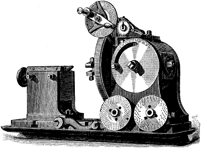
Fig. 1896.
For gear cutting, the universal head is enlarged and somewhat modified in design, as is shown in Fig. 1896, the worm and worm-wheel being much larger in diameter and exceedingly accurate by the following method having been adopted to test them: Two cast-iron disks were placed side by side on an arbor or mandrel held between the centres, and lines of division were marked across the edges of both of them (the index plate, of course, being used for the division). The disks were then separated and one of them moved and the lines of division again compared with a microscope, and no sensible errors were apparent.
The provisions for taking up the wear of the worm and its bearings, and of the worm and its wheel, are as follows: The worm-shaft runs in compensating bearings of phosphor bronze, and the bracket carrying the worm-shaft is adjustable towards the worm-wheel by the means already described for the ordinary universal head, and this head is said to be capable of making divisions as fine as one minute of an arc, or dividing the circle into 21,600 parts.
The employment of a worm and a worm-wheel necessitates that the index pointer arm be given a certain number of revolutions, in order to move the spindle the requisite amount for all divisions except those equal in number to the number of teeth contained in the worm-wheel, and to avoid any mistake in counting the number of revolutions of this index pointer arm the following device is employed: On the worm shaft is a pin, and to the right of the index plate is a dial plate which is clearly shown in the engraving. The circumference of the latter is cut with ratchet teeth, and the length of the pin on the worm-shaft is such that at each revolution it moves one tooth of the dial plate. In front of the dial plate is a fixed pointer, and as the face of the ratchet wheel is graduated and marked 1, 2, 3, &c., it is obvious that the pointer shows how many revolutions the dial plate, and therefore the worm shaft, has made. After the requisite number has been made and the index pin has been set in the index wheel, the small lever, shown on the right of the dial plate, is moved and a spring brings the dial plate back so that its zero number comes back to the pointer ready to count the number of revolutions when the worm-shaft is revolved for the next division or movement of the worm and wheel. For this head there are three index plates drilled with 23 circles of holes, making, in combination with the worm and wheel, all divisions up to 90, all even divisions up to 180, with most of the other divisions between 90 and 180, or 135 divisions and multiples of these divisions up to 16,200. The index plates are interchangeable, and additional ones for other divisions may obviously be added.
The device for cutting spirals as arranged for hand feeding is shown in Fig. 1897, while in Fig. 1898 it is shown arranged for automatic feeding, and is shown in position on the machine.
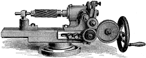
Fig. 1897.
Referring to Fig. 1897 the hand wheel operates a worm engaging with a worm-wheel on the shaft of the largest gear shown in the engraving. From this gear motion is conveyed through intermediate wheels to the pinion on the same shaft as the first bevel-gear, which obviously drives the bevel-gear shown on the end of the head. The back face of this latter gear is provided with index holes, and the usual index arm and pin are provided.
The change gears provided for this device are sufficient to cut twelve different pitches, ranging from one turn in 2 inches to one turn in 6 feet. Obviously right or left-hand spirals are produced according to the direction of revolution of the hand wheel.
VOL. II. EXAMPLES OF MILLING MACHINES. PLATE II.
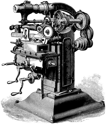
Fig. 1898.
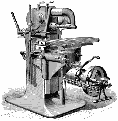
Fig. 1900.
In the general view, Fig. 1898, the device is placed upon a box bolted to the work table, and obtains its automatic feed through the medium of the worm for the table feed.
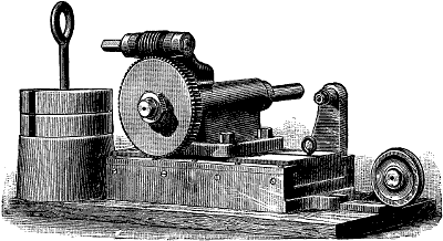
Fig. 1899.
The cam-cutting attachment, Fig. 1899, consists of a base bolted to the machine table and adjustable to any required position thereon. This base has a slide way in which a gibbed slide carrying a head is free to travel longitudinally. The pattern or former cam and the work are carried on the live spindle of the head, and the former cam is supported by circumferential contact with a roll carried on the vertical bracket shown on the right of the engraving. As shown, the device is arranged for cutting face cams, the cam-holding spindle being placed in line with the machine spindle. All that is necessary for cutting cylinder cams is to set the device with its spindle at a right angle to the machine spindle and move the supporting bracket so that its roller will meet the perimeter of the former cam. In either case the slide carrying the head is pulled forward by weights suspended over the wheel shown on the end of the base, and the feed is put on by revolving the spindle by means of the worm and worm-wheel shown in the engraving, the ordinary crank handle of the machine fitting the worm shaft.
A hand feed for cam cutters is preferable to the automatic feed, because in turning corners or curves the rate of the feed requires to be reduced in order to obtain smooth work.
Fig. 1900 represents a universal milling machine. The live spindle head is fitted to a horizontal slide on the top of the main frame, and may therefore be moved on that slideway to adjust the cutters to the work, the motion being effected by a pinion operating a rack on the underside of the head, as shown in Fig. 1901, which is a sectional view of the machine.
At the handle end of the pinion shaft there is provided a dial (which is seen in the general view of the machine) having an outer circle graduated to sixty-fourths of an inch, and an inner one graduated to fortieths of an inch. The driving shaft is at a right angle to the live spindle, and drives it by means of a hardened steel worm operating a bronze worm-wheel fast on the live spindle, and which runs in a trough of oil to provide ample lubrication.
Large image (176 kB).
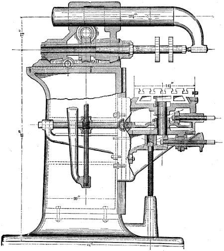
Fig. 1901.
The spindle is hollow and has tapered journals. The arm for supporting the outer end of the cutter arbor is cylindrical, and fits to a bore provided in the top of the frame of the head, which is split and has two binding screws. When these screws are loosened the arm may be readily adjusted for position, while when they are screwed up they lock the arm in its adjusted position. By this means the arm only projects out as far as the particular work in hand requires.
The knee for carrying the work table and chucking devices terminates at its top in a circular box cast open on top. This box is covered with a circular cap, in the upper face of which are the slideways or guides for the work table. The cap is recessed into the box so as to be kept central, and is fastened therein by an expanding ring operated by a single stud which projects through the walls of the box. This ring has a V-shaped groove on its periphery, which in expanding closes over corresponding bevelled ledges on the inside of both the cap and the box. The edge of the cap is graduated for cutting spirals.
By this arrangement the table can be set to move at any required angle with the live spindle and quickly clamped in position, while the ring being of larger diameter and bearing evenly around the entire circle, the cap is rigidly held. In this box, securely protected from the cuttings or dirt, is a large worm-gear secured to a short vertical shaft, on the upper end of which is a pinion projecting through the cap and engaging with a rack upon the underneath side or face of the work table. This shaft also carries a bevel-pinion which meshes with a pinion on the end of the short shaft seen projecting through the front of the box and provided with a hand crank, the hand lever shown behind this crank being for securing or releasing the cap to or from the box. The gearing is so arranged that one revolution of the hand crank traverses the work table a distance of 2 inches, thus providing for the rapid motion of the table to expedite putting in and taking out the work.
The knee is operated vertically by a pair of bevel-gears, the shaft for operating which is shown on the left-hand side of the knee. On this shaft is a pointer for an indexed dial, which has two graduated circles, the outer of which is divided so that each division corresponds to a knee motion of 1⁄32 of an inch, while the inner one denotes a knee motion of 1⁄1000 inch.
Automatic feed motion for the work table is provided as follows: The cone shaft projects through the live head and carries a leather-covered friction disk which drives a vertical shaft carried by a bracket hinged to the head. A small pulley splined on this shaft, and held at any point by a spring-pressed catch, bears against the leather-covered face of the disk, and it is obvious that the nearer to the centre of the disk the pulley is set the slower the latter will be revolved, and therefore the finer the feed will be, while the direction of revolution of the small pulley will be reversed if it be set on the upper half or above the centre of the disk, thus providing for reversing the direction of feed. By this arrangement both the rate and direction of the feed can be set without stopping the machine.
This vertical feed shaft carries a splined worm driving a worm-gear splined on a horizontal shaft which is carried by the knee, which has a projecting arm or bracket for carrying the back end of the shaft, so that the latter rises or falls with the knee. A worm on this horizontal shaft engages a large worm-wheel within the box and fast upon the short upright shaft, whose pinion engages the table rack and thus completes the feed motion.
It will be seen in the sectional view that the worm-wheel for the automatic feed is in one piece, with a smaller bevel-wheel engaging with a bevel-pinion for the hand feed.
A clutch joint near the centre of the horizontal shaft affords the means for putting the automatic feed either into or out of action.
The table can be fed its full length in either direction, and when placed so that one end will pass the main frame or column may be swung around parallel to the spindle, thus enabling the machine to be used as a boring mill for short holes, or by turning the table a half revolution work may be done on both sides of a piece at one chucking, thus insuring perfect parallelism.
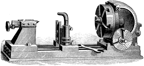
Fig. 1902.
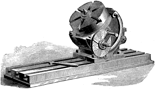
Fig. 1903.
The construction of the index head of this machine is as follows: Fig. 1902 represents it on a plate with a back centre and a centre rest, and Fig. 1903 represents the head elevated. The head is a hollow box, the outline of which is about two-thirds of a circle. The opening, in front or chord side, is surrounded by a flange, and bored out as large as permissible. This forms the front bearing of the spindle and face plate, which is cast in one piece. A rear and smaller bearing is provided on the circular part of the case. The end of the spindle projects through the case, and is held from coming out by a recessed nut and washer. The spindle also carries an accurately-divided steel gear of sixty teeth. This gear is made as large as will go through the opening in front, or about 6 inches in diameter. Directly under this gear the box is pierced from the side. In this opening is inserted a long bush, through which a steel worm engages with the gear. An index plate secured to the outer end of the bush, and an adjustable arm and index pin attached to the projecting end of the worm, complete the dividing mechanism. Substantial but delicate adjustments are provided for eliminating lost motion.
On the periphery of the case is turned a dovetail shoulder, which slides around in a corresponding groove in the quadrant-shaped base. The case is graduated on its edge, and may be clamped at any angle of elevation from 15 degrees below a horizontal line to a vertical position, being equally stable in all positions. The face plate is no farther from the bed in one position than another, and being seated to the case, and adapted to hold work directly on its face, forms a stiff and substantial device for cutting bevel-gears and other work requiring angular motion. The tail centre is also of a strong and substantial design.
An adjustable centre rest of novel design also accompanies the outfit, and an extra bed or table, with straps for securing it to the table of the machine. With the centres arranged on this bed the line of centres may be set at any angle with the sliding table, A sufficient number of index plates are provided to divide all numbers up to 100 and all even numbers to 200.
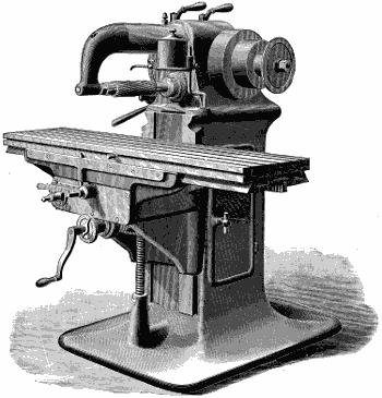
Fig. 1904.
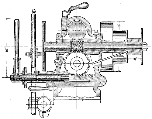
Fig. 1905.
Fig. 1904 represents a machine in which the base column and the head are constructed upon the same design as that in Fig. 1900, but the circular top and cap are replaced with a larger and heavier knee of rectangular form, and the table is longer. A cross sectional view of the head is shown in Fig. 1905. The bearings for the live spindle are solid bushes slightly tapered, and are driven into the head from each end up to and against the flanges.
The spindle is of tool steel 31⁄2 inches in diameter at the front bearing, tapering uniformly 3⁄4 inch per foot to the back end. This simple construction allows the spindle to be perfectly ground, and accurately fitted to the boxes by scraping. After this is done the spindle is withdrawn about the 1⁄100 part of an inch, and a flat babbitt metal washer fitted to exactly the space between the shoulder on the spindle and the front box. A check nut and sliding collar on the back end holds the spindle in place. A perfectly uniform space for oil is thus formed between the spindle and bearings. The worm-gear is forced tightly on the taper spindle with a nut, and keyed to prevent turning.
The spindle has a hole 19⁄16 inches through its centre, tapering in front to receive the arbor to 17⁄8 inches. The taper is made 1⁄2 inch per foot, and for ordinary work is sufficient to prevent the arbor turning, but for driving gangs or large mills an arbor is used having a hexagon enlargement just outside the spindle. A cap to screw over the end of the spindle, having a hexagon opening in it to fit the arbor, completes a positive driver that has none of the objections to cutting a mortise or keyway in the spindle or otherwise disfiguring it. This cap protects the thread on the spindle, and may be readily removed for a face plate or large facing mills.
The cone shaft and its bearings are made independent of the head. A long sleeve, which is provided with a large flange, projects through cored openings in the side of the head. The bosses around these openings are faced off square and parallel, and a large flat ring threaded on the end of the sleeve draws the flange against the opposite face. The large end of the sleeve is counterbored to receive the worm, and is cut away on the under side to allow the worm to drop into mesh with the gear. The worm is feathered on the shaft, the thrust of the worm being taken in one direction against the shoulder in the sleeve, and in the opposite direction (the machine can be driven either right or left-handed) against the end of a bush, which is screwed in the sleeve and forms one bearing for the cone shaft. Friction washers are placed to form the step, and all wear or lost motion can be removed by screwing in the bearing, which, when adjusted, is prevented from turning by a small set-screw. The cone-shaft bearings are babbitt lined, but the spindle bearings are made of cast iron, in which steel scrap has been melted. The worm-gear has 40 teeth, and the worm is triple threaded, thus making a back gear equivalent to 40⁄3, or 131⁄3 to 1. As the sleeve does not fit the openings in the head, the worm and gear may be readily adjusted to each other at all times, and held firmly and squarely in place by drawing the flange tight against the side of the head. Set-screws through the head prevent accidental displacement of the sleeve after being adjusted.
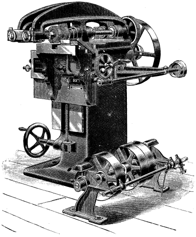
Fig. 1906.
Fig. 1906 represents a double spindle milling machine. The second spindle is for driving the finishing cutters, so that as the two spindles are capable of independent adjustment, the work may be finished at one feed traverse, thus avoiding the necessity of removing the work or making special adjustments.
VOL. II. EXAMPLES OF MILLING MACHINES. PLATE III.
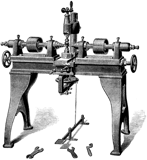
Fig. 1907.
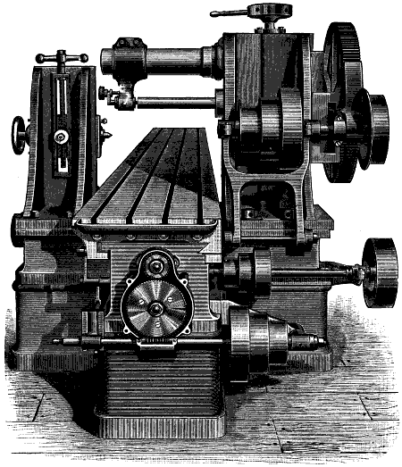
Fig. 1908.
Fig. 1907 represents a milling machine for globe valves and other similar work. Here there are two cutter-driving spindles, one on each end of the bed, and the work is held vertically. It is provided with an index wheel for milling squares, hexagons, or octagons, and the pen for the index wheel is operated by treadle. The work is fed across the bed, the chucking devices being carried on a slide rest. In the figure a globe valve is shown chucked between two plugs or arbors fitting its bore, but it is obvious that centres or other work-holding appliances may be used to suit the kind of work.
Fig. 1908 represents an eighty-inch milling machine, the table of which has longitudinal motion; and provision for vertical and crosswise movements are made in the head which carries the driving mechanism.
The machine table sets low on a bed supported by four box legs, and is actuated by a steel screw driven by a worm and worm-gear connected with a pair of spur-gears. The gearing is outside the bed, and therefore accessible, and is protected by a shield, as shown in cut. The arrangement for belting to feed works is also shown too plainly to need description. The head upon which the spindle carrier is mounted travels in ways upon the bed, and is adjusted crosswise on it by means of a screw connected with a hand wheel, partially shown at the left of engraving. For convenience and ease in fine adjustment this wheel, and also the wheel at top of machine, connected with the elevating screw, are worked by a hand lever, the wheels having sockets in their periphery for this purpose.
The carrier, upon which is mounted the driving spindle, is gibbed to the head, and has a vertical range sufficient to allow work 18 inches high to pass under centres. From this carrier projects a large arm for outside centre support of mill spindle, intended for use on work where a back stand is not admissible. There is, however, as may be seen, a back stand or tailstock of a very solid character. The arm is readily removable, when desired, or the tailstock can be slid off its seat if required. In most cases, however, the arm need not be removed, the yoke on it being swung up out of the way, leaving the centre of mill arbor free to engage with that on the back stand. This combination provides for operating on a wide range of work.
As shown in the engraving, the space between head and tailstock is about 24 inches, but if required the tailstock can be made to travel in line with the head, and its support be extended to any distance desired.
The method of driving the spindle is simple and strong, and allows of free adjustment of the spindle without disarrangement of the driving and feed belts.
The cone, which is made for 31⁄2 inch belt, is mounted in a stirrup which is pivoted to the bed, and the pinion which engages with the driving gear on the spindle is held at correct distance by a connecting yoke, and is driven by a feather.
The machine has longitudinal feed only, but where it is desired an automatic feed motion can be applied to the elevating screw in the head, giving feed in a vertical direction.
The table is arranged to be run back rapidly by power, by a device which is not seen in the engraving. As the table weighs one ton, the relief to the operator by this improvement is obvious.
All the operations of the machine are intended to be conducted from the front side, without any change in the position of the operator. The feed can be thrown out by hand at any moment by means of a rod which connects with the latch shown in the front of the cut, and the power quick-return applied; or the table can be run back by hand, and the feed thrown in by a foot lever, which lifts the drop box shown in front of cut. Adjustable dogs automatically drop the feed motion at any point.
The machine is massive in all its parts, and is intended for heavy milling of any description, but more particularly for shafting, railroad, or engineering shops, being specially adapted for key-seating long and heavy shafting, finishing guide bars, connecting rods, &c.
Its weight is 7,500 pounds. The work table is 7 feet long by 20 inches wide; length of longitudinal feed, 84 inches; distance between uprights, 24 inches. The cast-steel spindle is 4 inches in diameter, and the mill arbor 21⁄2 inches diameter. Arm for outer centre support 5 inches diameter at its smallest part.
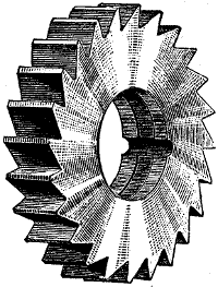
Fig. 1909.
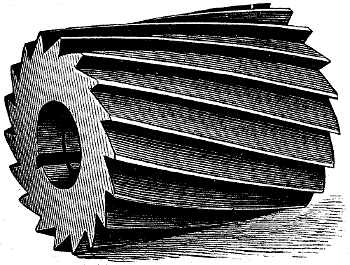
Fig. 1910.
Milling Cutters or Mills.—The simplest form of milling cutter is that shown in Fig. 1909, the teeth being equidistantly arranged upon the circumference only. Its size is usually designated by its length, which is termed the face. Thus a cutter having its teeth parallel to its axis and an inch long would be said to have 1 inch face. Cutters of more than about half an inch face usually, however, have their teeth cut spirally, as in Fig. 1910; the degree of spiral is one turn in a length of 3 feet for cutters between 21⁄4 and 4 inches in diameter. For cutters of less than 21⁄4 the degree in the spiral is increased; thus for an inch cutter, the degree is one turn in 15 inches, while for 6 inches one turn in about 60 inches is used.
In the following table is given the sizes of cutters as made by one company, the bores being 1 inch.
Width of face. Diameter of cutter. Width of face. Diameter of cutter.
inch. inch. inch. inch. inch. inch. inch. inch.
1⁄8 2 1⁄2 3 4 15⁄16 2 1⁄2 3 4
3⁄16 2 1⁄2 3 4 1 2 1⁄2 3 4
1⁄4 2 1⁄2 3 4 1 1⁄8 2 1⁄2 3 4
5⁄16 2 1⁄2 3 4 1 1⁄4 2 1⁄2 3 4
3⁄8 2 1⁄2 3 4 1 1⁄2 2 1⁄2 3 4
7⁄16 2 1⁄2 3 4 1 3⁄4 2 1⁄2 3 4
1⁄2 2 1⁄2 3 4 2 2 1⁄2 3 4
9⁄16 2 1⁄2 3 4 2 1⁄4 2 1⁄2 3 4
5⁄8 2 1⁄2 3 4 2 1⁄2 2 1⁄2 3 4
11⁄16 2 1⁄2 3 4 3 2 1⁄2 3 4
3⁄4 2 1⁄2 3 4 3 1⁄2 2 1⁄2 3 4
13⁄16 2 1⁄2 3 4 4 2 1⁄2 3 4
7⁄8 2 1⁄2 3 4
The keyways are semicircular, the key being composed of a piece of No. 25 Stubbs steel wire.
The following is a table of the sizes of milling cutters made by another company.
Width of face. Diameter of cutter. Size of hole. Width of face. Diameter of cutter. Size of hole.
inch. inch. inch. inch. inch. inch.
1⁄8 2 1⁄4 1 3⁄4 2 7⁄8 1
3⁄16 2 1⁄4 1 7⁄8 2 7⁄8 1
1⁄4 2 1⁄2 1 1 2 1⁄2 1
5⁄16 2 1⁄2 1 1 1⁄4 2 1⁄2 1
3⁄8 2 5⁄8 1 1 1⁄2 2 1⁄2 1
7⁄16 2 5⁄8 1 1 3⁄4 2 1⁄2 1
1⁄2 2 3⁄4 1 2 2 1⁄2 1
9⁄16 2 3⁄4 1 2 1⁄2 2 1⁄2 1
5⁄8 2 3⁄4 1 3 2 1⁄2 1
11⁄16 2 7⁄8 1
Cutters of 1 inch face and over have teeth of a spiral form.
The object of providing spiral teeth is to maintain a uniformity of cutting duty at each instant of time.
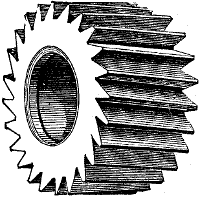
Fig. 1911.
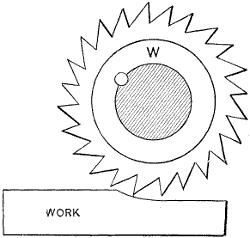
Fig. 1912.
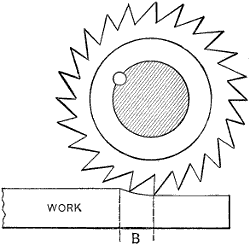
Fig. 1913.
Suppose, for example, that the teeth are parallel to the cutter axis, when the cutter first meets the work the tooth will take its cut along its full length at the same instant, causing in wide cuts a jump to the work because of the spring of the various parts of the work-holding devices, and of the cutter driving spindle; furthermore as the cutter revolves the number of teeth in action upon the work varies. Thus in Fig. 1912 it is seen that one tooth only is in action, but when the cutter has revolved a little more there will be two teeth in action, as shown in Fig. 1913. This variation causes a corresponding variation of spring or give to the machine, producing a surface very slightly marked by undulations. But if the teeth are cut spiral the cut begins at one end of the tooth and proceeds gradually along it, thus avoiding violent shock, and after the cut is fairly started across the work the length of cutting edge in action is maintained uniform, producing smoother work, especially in the case of wide surfaces and deep cuts.
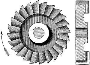
Fig. 1914.
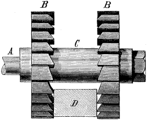
Fig. 1915.
When the cutter is required to cut on the sides of the work as well as on its upper face it is termed a face cutter, and its side faces are provided with teeth, as shown in Fig. 1914; and when these cutters are arranged in pairs as in Fig. 1915, so as to cut in the side faces only of the work d, they are termed twin or straddle mills, both being of the same diameter.
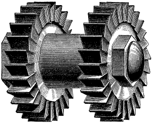
Fig. 1916.
In mills or cutters used in this way the cutting duty is excessive on the outer corners of the teeth, which, therefore, rapidly dull; hence it is usual to provide teeth on both sides of the cutter, as in Fig. 1916, so that after having been used in the position shown in the engraving until the teeth are dull the positions of cutters may be changed, bringing the unused cutting edges into use.
Twin or heading cutters are right and left hand, a right-hand one being that in which the teeth at the top of the wheel revolves towards the right, while a left-hand one revolves (at the top) towards the left.
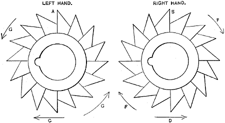
Fig. 1917.
If the machine is belted so that it can be revolved in either direction, both sides of the cutter may be utilised by taking the cutters off the arbor, turning them around and then replacing them in their original positions on the same. Thus in Fig. 1917 we have at a a left-hand cutter that if reversed upon its arbor would be a right-hand one as at b, and it is obvious that the direction of revolution must be in each case as denoted by the arrows f g, which are in opposite directions. In this case the direction of work feed must be reversed, the work for a feeding in the direction of c, and that for b in the direction of d. It is to be observed, however, that the cutter could not be reversed if it was driven by an arbor that screwed upon the driving spindle of the milling machine. For if the machine has a right-hand thread then the cutter must revolve in the direction of g, and the work feed must be in that of c; whereas if the machine spindle drives its chucks, arbors, &c., by a left-hand thread, then the direction of cutter revolution must be as at f, and that of work feed as at d. But if the cutters are upon an arbor that is driven by a conical seat in the machine spindle, or by any other means enabling the arbor to revolve in either direction without becoming released from that spindle, then the cutter may be simply turned around and the feed direction reversed, as already explained. The reason for reversing the direction of feed when the direction of cutter revolution is reversed is as follows:—
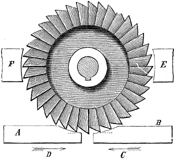
Fig. 1918.
In Fig. 1918 a and b represent two pieces of work of which b is to be fed in the direction of arrow c, so that the pressure of the cut tends to force the work back from under the cutter, whereas in the case of the work a, feeding in the direction of d, the teeth act to pull the work beneath the cutter, which causes tooth breakage.
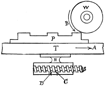
Fig. 1919.
Suppose, for example, that in Fig. 1919 p is a piece of work fastened to the table t, feeding in the direction of a, the cutter w revolving in the direction of arrow b, n representing the feed nut operated by the feed screw s. Now while the table is being pulled in the direction of a, the sides c of the feed screw thread will bear against the sides of the thread in the nut, and whatever amount of looseness there may be between the threads of the screw and nut will in this case be on the sides d of the threads. So soon, therefore, as the wheel meets the work p, it will suddenly pull the work forward to the amount of the play or looseness on the sides d of the threads, and this in addition to the feed given by the rotating screw s, would cause the wheel to lock upon the work surface.
In all milling operations, therefore, the work is fed against the cutter as at b, in Fig. 1918, unless, in the case of twin mills, it is fed (as at e and f in the same figure) in the middle of the cutters, in which case it is preferable to present it as at f, so that the pressure of the cut will tend to hold the work down to the table, and the table down upon its guideways. This position of the work presents some advantages for small work which will be explained hereafter.
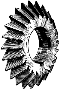
Fig. 1920.
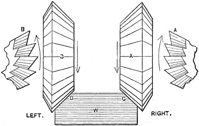
Fig. 1921.
Fig. 1920 represents angular cutters, the teeth being at an angle to the cutter axis. These cutters are made right and left as at a and b in Fig. 1921, the teeth of a being cut in the opposite direction to those at b, so as to be able to cut equal angles on the work when these angles lie in opposite directions, as c and d in the figure. Furthermore these cutters are sometimes screwed to their arbors, and can therefore be revolved in one direction only, which prevents their being turned around end for end, even though the machine be so belted as to be capable of revolving its spindle in either direction.
The angular cutters shown in Fig. 1921 have their teeth arranged for a Brainard milling machine, in which the live spindle has a right-hand thread for driving the chucks, arbors, &c.; hence the direction of cutter revolution, and the arrangement of the teeth are as in the figure.
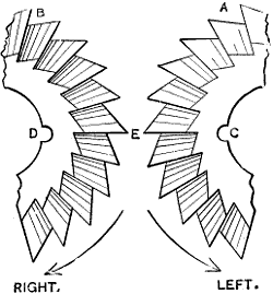
Fig. 1922.
In Fig. 1922 are segments of two wheels, a and b (corresponding to a and b in Fig. 1921), but with their teeth arranged for a Brown and Sharpe milling machine, in which the machine spindle has a left-hand thread; hence the direction of cutter revolution is reversed, as denoted by the arrows in the two figures.
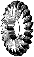
Fig. 1923.
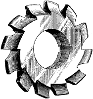
Fig. 1924.
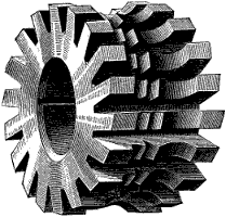
Fig. 1925.
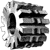
Fig. 1926.
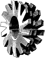
Fig. 1927.
Fig. 1923 represents a round edge cutter; and it is obvious that the curvature or roundness of the cutting edges may be made to suit the nature of the work, whether the same be of regular or irregular form. In cutters of this description it would be a difficult matter to resharpen the teeth by grinding their backs, hence they are ground on the front faces; and to maintain the form or profile of the cutting edges, notwithstanding the grinding, we have a patent form of cutter, an example of which is shown in the gear tooth cutter in Fig. 1924. The backs of the teeth are of the same form throughout their entire length, so that grinding away the front face to sharpen the cutting edge does not alter the contour or shape of the cutting edge. This is of especial advantage in cutters for gear teeth, and those for irregular forms, Figs. 1925, 1926, and 1927 forming prominent examples.
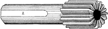
Fig. 1928.
End mills or shank cutters are formed as in Fig. 1928, the shank sometimes being made parallel with a flat place at a, to receive the set-screw pressure, and at others taper, the degree of taper being 1⁄2 inch per foot. The hole at the end facilitates both the cutting of the tooth in the making and also the grinding. Shank cutters may be used to cut their way into the work, with the teeth on the end face, and then carry it along, bringing the circumferential teeth into operation; or the end teeth may be used to carry the cut after the manner of a face cutter.
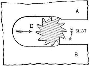
Fig. 1929.
Shank cutters are rarely made above an inch in diameter, and are largely used for cutting grooves or recesses, and sometimes to dress out slots or grooves that have been cast in the work, as in the case of the steam and exhaust ports of steam engine cylinders. In work of this kind the direction of the feed is of great importance and must be varied according to the depth of cut taken on the respective sides of the cutter. Suppose, for example, that the conditions are such as illustrated in Fig. 1929, the cut being deepest on the side a of the slot, and the cutter must be entered at the end of the slot and fed in the direction of d, so that the pressure of the cut may tend to push the cutter back, it being obvious that on the side b the cutter has a tendency to walk or move forward too rapidly to its cut, and if the cut was heaviest on that side it would do, this increasing the cut rapidly and causing tooth breakage.
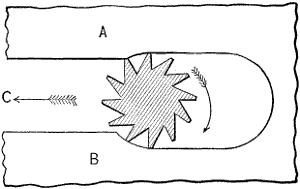
Fig. 1930.
This tendency, however, is resisted by the pressure on the side a of the slot, which acts, as already stated, to push the cutter back. In starting the cutter therefore, it is necessary to do so at that end of the slot that will cause the deepest cut to act in the direction to retard the feed. Suppose, for example, that the heaviest or deepest cut, instead of being on the side a of the slot, as in Fig. 1929, was on the side b, and in that case it would be necessary to start the cut from the other end of the slot as in Fig. 1930, the arrow c denoting the direction of feed.
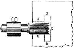
Fig. 1931.
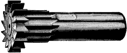
Fig. 1932.
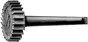
Fig. 1933.[31]
Similarly when a groove has been roughed out from the solid, and it is determined to take a finishing cut, the direction of the feed for the latter is of importance. Suppose, for example, a T-groove is to be cut, and that a slot is first cut with a shank cutter as in Fig. 1931, leaving a light finishing cut of, say, 3⁄64 inch to finish the neck to the dotted lines a b, and entering to within 1⁄16 inch of the full depth as denoted by line c. The enlarged part of the groove may then be cut out, leaving about 3⁄64 inch at the top and bottom, d and e, the cutter having a plain shank (as in Fig. 1933), whose diameter should just clear the narrow part of the groove already roughed out. The work will then be ready for the finishing cutter, formed as in Fig. 1932, whose teeth (on both the shank and the enlarged end) should have a diameter of 3⁄32 less than that of the finished slot. In taking the finishing cut this cutter must be set first to cut the sides b e to finished size, the direction of the feed being such that the pressure of the cut acts to push the cutter back as already explained, and when the cut is finished on this side the finishing cut may be put on the side a d, without traversing the cutter back, or in other words the feed must be carried in the opposite direction, so that the cutter will run under the cut and be pushed back by it, so as to prevent it from running forward as explained with reference to figure.
For ordinary work not requiring great truth, however, the first cutter, Fig. 1931, may be made of the finished diameter, and be followed by a cutter such as in Fig. 1933, also of the finished diameter.
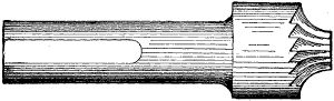
Fig. 1934.[32]
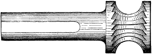
Fig. 1935.
When a shank-cutter is required to enter solid metal endways, as in the case of cutting grooves around the circumferential surface of a cylinder, it is necessary to drill a hole to admit the cutter, leaving a light finishing cut for the diameter of the cutter, and sufficient in the depth to let the end face of the cutter remove or square up the cone seat left by the drill. Shank cutters may obviously be made taper, or to any other required angle or curvature, Figs. 1934 and 1935 being examples which can be used in situations where other cutters could not, as for example on the arms or spokes of wheels.
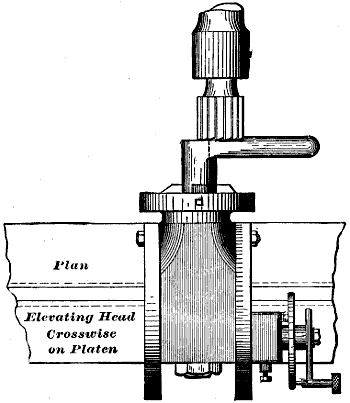
Fig. 1936.
Fig. 1936, from The American Machinist, represents an example of the employment of shank cutters, the work being a handle for a lathe cross-feed screw, and it is obvious that the double cornering cutter may be used upon both edges, and the cut being carried around the hub by the parallel part of the cutter; the whole of the work on the handle including the boring, if the hole is cast in, may be done by the shank cutter, the handle end being finished and the boring done first, the hub being finished on an arbor.
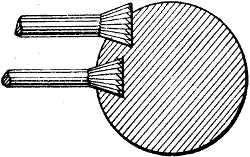
Fig. 1937.
Shank mills may obviously be made of various shapes; thus in Fig. 1937 is shown two applications of an end or shank mill, one for cutting a dovetailed groove and the other an angular one. In the case of the dovetail groove the cutter will work equally well, whether it be used on straight or spiral grooves; but this is not the case with angular grooves for reasons which are explained with reference to angular cutters and spiral groove cutting.
Shank cutters are provided with finer teeth than ordinary cutters, the following being the numbers of teeth commonly employed for the respective diameters:—
Diameter of cutter 1⁄8 or 3⁄16 inch, number of teeth 6
„ „ 1⁄4 „ „ „ 7
„ „ 3⁄8 „ „ „ 8
„ „ 1⁄2 „ „ „ 8
„ „ 5⁄8 „ „ „ 10
„ „ 3⁄4 „ „ „ 10
„ „ 7⁄8 „ „ „ 12
„ „ 1 „ „ „ 14
The front faces of the teeth are radial as in other cutters, the angle of the back of the tooth being 40° for the smaller, 50° for the medium, and 60° for an inch cutter.
Fly cutters are single-toothed cutters, or rather tools, that are largely used by watchmakers for cutting their fine pitches of gear wheels.
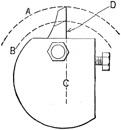
Fig. 1938.
Fig. 1938 represents a fly cutter in place in its holder or arbor, its front face d being in line with the axis c of the arbor.
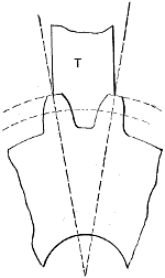
Fig. 1939.
Let it be required to make a fly cutter for a very fine pitch of gear tooth, such as used for watches, and a template, shown greatly magnified at t in Fig. 1939, is made to fill a space and one half of each of the neighboring teeth. From this template a cutting tool is made, being carefully brought to shape with an oil-stone slip and a magnifying glass. This tool is used for the production of fly cutters, and may be employed by either of the following methods:—
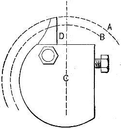
Fig. 1940.
The piece of steel to form the cutter is fastened in an arbor back from the centre, as at d in Fig. 1940, and is then cut to shape by the tool before referred to. It is then set for use in the milling machine, or in such other machine as it may be used in, in the position shown in Fig. 1938, its front face d being in line with the axis c of the arbor. The change of position has the effect of giving the tool clearance, thus enabling it to cut while being of the same shape throughout its whole thickness; face d may be ground to resharpen the cutter without altering the shape it will produce. It is this capacity to preserve its shape that makes the fly cutter so useful as a milling machine tool, since it obviates the necessity of making the more expensive milling cutters, which, unless made on the principle of the Brown and Sharpe cutters, do not preserve their shapes.
It is to be observed, however, that a fly cutter made as above does not produce work to exactly correspond to the template it was made from, because moving it from the position it was made in (Fig. 1938) to the position it is used in (Fig. 1940) causes it to cut slightly shallower, but does not affect its width.
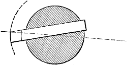
Fig. 1941.
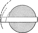
Fig. 1942.
Another method of cutting up a fly cutter by the tool made to the template is shown in Fig. 1941. The blank cutter is placed at an angle to an arbor axis, and is cut to shape by the tool. For use it is placed in line with the arbor axis as in Fig. 1942, the change of position here again giving clearance as shown by the dotted arcs, the inside ones showing the arc the cutter revolved on when it was in the arbor in Fig. 1938. Here again, however, the change of position causes the fly cutter to produce a shape slightly different from the template to which the first tool was made, hence the best method is as follows:—
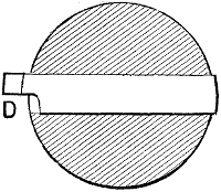
Fig. 1943.
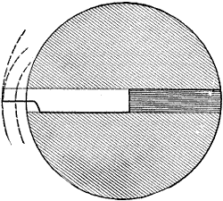
Fig. 1944.
The blank is let into an arbor of small diameter, as in Fig. 1943, its face d being in line with the arbor axis. It is then cut up with the tool made from the template. For use it is set in a larger arbor, as in Fig. 1944, the difference in its path of revolution giving it the necessary clearance. Thus, in the figure the inner dotted arcs show the path of revolution of the cutter when it was in the small arbor, and the outer arc of the path in the large arbor. The front face can be ground without altering the shapes; the cutter will produce this front face, being kept in line with the arbor axis by grinding the body of the steel as much as the front face is ground when it is resharpened. Curves or irregular shapes may be readily produced and preserved by fly cutters.
It is obvious, however, that when the tool made to the original template is worn out, another must be made, and to avoid this trouble and preserve the original shape beyond possible error, we have recourse to the following additional method:—
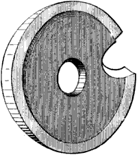
Fig. 1945.
With the tool made from the template we may cut up a wheel, such as in Fig. 1945, and this wheel we may use as a turning tool to cut up fly cutters, the principle of the wheel cutter having been shown in connection with lathe tools. It may here be pointed out, however, that if a wheel or circular cutter, as it is termed, is to be used, we may make the template, and the master tool we make from it, for one side of a tooth only, and use the master tool to cut up one side only of the corner of the circular cutter, as shown in Fig. 1945.
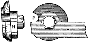
Fig. 1946.
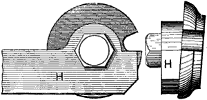
Fig. 1947.
The method of using the circular cutter is illustrated in Fig. 1946, in which h is a holder, whose end face p is level with the axis of the cutter, which is held to the holder by a screw. The side face of the holder is out of the vertical so as to give the cutter side clearance. A second holder has its side face inclined in the opposite direction, thus enabling the one edge of the circular cutter to be used as a right or as a left-hand tool and insuring uniformity, because the same edge of the circular cutter is used in both cases, so that if used for say a tool for a gear tooth, both sides of the tool will be cut from the same side of the circular cutter.
It is obvious that instead of having one continuous cutter, the necessary breadth of cutter face may be obtained by means of two or more cutters placed side by side. Thus to mill a piece of work two inches wide we may use two cutters of an inch face each (both of course being of equal diameter), or we may use one cutter, of 11⁄4 inch and another of 3⁄4 inch face. It is preferable, however, to use two cutters of an inch face each, and to set one beam left-hand and the other right-hand spiral teeth, because spiral teeth have considerable tendency to draw the machine spindle endways in its bearings, because the teeth correspond to a certain extent to a screw, and the work to a nut. A cutter with a left-hand spiral exerts end pressure tending to draw the driving spindle out from its bearings, while a right-hand one tends to push it within them; hence by making the two cutters of equal length and of the same degree of spiral, the effect of one cutter offsets that of the other. Furthermore, it is found that the tendency to chatter which increases with an increase in the width of the work, is diminished by using right and left spiral cutters side by side.
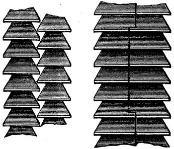
Fig. 1948.
In order that the cutting edges of cutters placed side by side in this way may be practically continuous so as not to leave a line on the finished work, the teeth may be made to overlap in two ways as in Fig. 1948, both representing magnified portions of cutters. In the method shown on the left of the figure the usefulness of either cutter to be used singly is not impaired, all that is necessary to insure the overlapping being to cut the keyways in different positions with relation to the teeth; whereas on the left of the figure neither cutter would be efficient if used singly, except upon work as narrow as the narrowest part of the cutter. On the other hand, however, it affords excellent facilities for grinding, since the two cutters may be ground together, thus ensuring that they be of equal diameters except in so far as may be influenced by the wear of the emery wheel, which is, however, almost inappreciable even in cutters of considerable width of face. In the method shown on the left there is the further advantage that as the teeth are not in line the cutting action is more continuous and less intermittent, the arrangement having in a modified degree the same advantage as the spiral cutter.
In both methods some latitude is given to adjust the total width of face by placing paper washers between the cutters. If the plan on the right is employed the projections may occupy one-fourth of the circumference, there being two projections and two depressions on one end of the cutter. When cutters of different diameters and shapes are put together side by side on the same arbor the operation is termed gang milling.
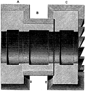
Fig. 1949.
Thus, in Fig. 1949 is shown a sectional view of a gang of three mills or cutters, a, b, and c, of which a and c are recessed to admit of the ends of b passing within them. The heavy black line representing a paper washer inserted to adjust the distance apart of a and c, it being obvious that this gives a means of letting them together after their side teeth at d and e have been ground. As shown in the figure, a has teeth on one only of its sides, while c has them on both sides as well as in its circumference, while all three are of different widths of face. This would capacitate a only for the inside cutter, as in the figure, while b would be serviceable only when there was a cutter on each side of it; or if used singly, only when its face overlapped the width of the work on each side. But c, being cut on each side, could be used singly for grooving or recessing, or for plain milling, or in the position of b or a in the figure; hence it is preferable in gang milling for general purposes to provide teeth on both sides as well as on the circumference of the mill or cutter. But if a gang of mills are to be made for some special purpose, and used for no other, the teeth may be provided on the sides or not, as the circumstances may require.
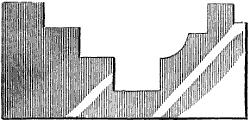
Fig. 1950.
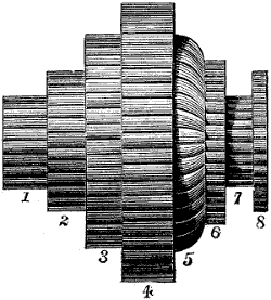
Fig. 1951.
Suppose, for example, that steps, such as shown in Fig. 1950, were required to be cut in a piece of brass work, and that, the work requiring to be very true, a set of roughing and one of finishing cutters be used, then the latter may be put together as in Fig. 1951, there being eight separate cutters, and their ends being slightly recessed but without teeth. Such cutters would wear a long time and may be readily sharpened, and there being no side teeth, the widths of the cutters, individually and collectively, would not be altered by the grinding; hence no readjustment with washers would be necessary. The tooth corners must, however, be kept sharp, for in proportion as they get dull or blunt, the sides of the cutter wedge in the work, causing friction and extra power to drive them as well as producing inferior work.
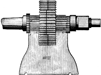
Fig. 1952.
Fig. 1952, which is from an article by John J. Grant, represents a gang of cutters arranged to mill out the jaws and the top faces of a head for a lathe; and it is obvious that a number of such heads may be set in line and all milled exactly alike.
The Number of Teeth in Mills or Cutters.—The teeth of cutters must obviously be spaced wide enough apart to admit of the emery wheel grinding one tooth without touching the next one, and the front faces of the teeth are always made in the plane of a line radiating from the axis of the cutter.
In cutters up to 3 inches in diameter, it is good practice to provide 8 teeth per inch of diameter, while in cutters above that diameter the spacing may be coarser, as follows:—
Diameter of cutter 6 inches, number of teeth in cutter 40
„ „ 7 „ „ „ 45
„ „ 8 „ „ „ 50
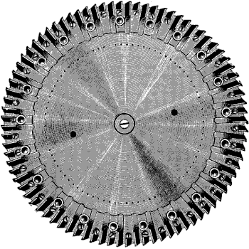
Fig. 1953.
Milling Cutters with Inserted Teeth.—When it is required to use milling cutters of a greater diameter than about 8 inches, it is preferable to insert the teeth in a disk or head, so as to avoid the expense of making solid cutters and the difficulty of hardening them, not merely because of the risk of breakage in hardening them, but also on account of the difficulty in obtaining the uniform degree of hardness or temper. The requirements for the heads for inserted teeth are, that the teeth shall be locked firmly in position without lost motion, and be easily set to gauge, ease of insertion and of removal being of secondary consideration, as such teeth should be ground in their places in the head, and are therefore rarely removed. The manner in which these requirements are attained in the Brainard heads are, as shown in Fig. 1953. A disk of wrought iron of suitable thickness and diameter is turned and squared, then a circle of index holes corresponding to the number of teeth required is drilled in its face; this circle of holes is used to insure the accurate spacing of the dovetail seats for the teeth, and to attain accuracy in grinding the teeth. All the teeth are a driving fit, and being milled are, of course, interchangeable. In order to obtain a larger number of teeth in a given size of head than could be got into the face, only one-half of the teeth are dovetailed into the periphery of the head and the other half into its face, but yet all the teeth are effective for face cutting, the construction being as follows:—
Between each pair of face teeth is a slit sleeve, which meets them and has a taper base, through which passes a taper bolt having a nut on the back face of the head. Tightening this nut expands the sleeve, thus locking the pair of teeth in their dovetail grooves. The circumferential teeth are each counter-based to receive a screw tapped in the head, and are firmly locked thereby. This affords a simple and reliable means of inserting and adjusting other teeth with the certainty that they will be true with those already in use.
The large size of some of these heads makes it convenient and desirable to grind them in their places on the machine, and for this purpose a special grinder is made by the same company. This grinder sets upon the machine table and has a point or pin for the index holes or the cutter head; by this means the grinding may be made as accurate as in small milling cutters.
The head shown in figure represents one that has been in use ten years, its cutters having been renewed but once; it is 28 inches in diameter, contains 84 teeth, and weighs 400 lbs.
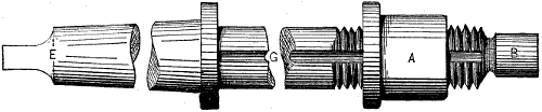
Fig. 1954.
Arbors for milling cutters may be driven in two ways. In the first the shank is made taper to fit the taper bore of the live spindle. The standard taper is 1⁄2 inch per foot of length. The keyway is semicircular, as shown at g in Fig. 1954, the key consisting of a piece of No. 25 Stubbs steel wire, which being of uniform diameter enables a number of keys of different lengths to be easily obtained or made, and the nut is usually cylindrical, having two flat sides, a.
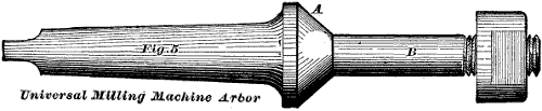
Fig. 1955.
Fig. 1955 (from The American Machinist) represents an arbor, having a cone at a, so that the cutter bore being coned to correspond, the cutter will run true, notwithstanding that it may not fit the stem b. It is obvious, however, that the nut and washer must be made quite true or the cutter will be thrown out of line with the arbor axis and therefore out of true, and also that such an arbor is not suitable for cutters of a less width of face than the length of the cone a.