Volume 2 — Chapter XXIX.—ERECTING ENGINES AND MACHINERY.
Reading edition
In engines having suspended guide bars, it is not uncommon to set those bars by the working parts of the engine, instead of by lines. This is an advantage when the parts of the engines are not taken down, and, if care is taken, will make a true and smooth working job; but otherwise, it is likely to introduce errors in the lining of the engine, which throw it out of proper line, and cause a great deal of friction.
The proper method of setting the bars depends upon the condition of the engine as to wear. Suppose, for example, that a new piston head has been put in, then, if the gland is new also, or is a good fit to both the piston rod and the bar of the stuffing box, the bars may be set as follows:—
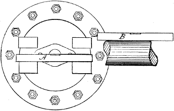
Fig. 2518.
Place the piston at the back end of the cylinder, and put the cross head and guide blocks in proper place on the rod. Put up the bottom guide bars so that they just touch the cross-head guides. Now, in adjusting these bottom bars there are two essential points: first, that the plane of their upper surfaces shall stand parallel with the axial line of the main shaft, and secondly, to place the upper surface parallel with the axial line of the cylinder (it being of course assumed that the cylinder and crank shaft are in proper line). The first of these essential points will be attained when a spirit-level, placed truly along the bore of the cylinder, shows the bubble to stand in the same position in the tube, as it does when placed upon and along the bar. The second will be attained when a spirit-level, placed across the bars, as in Fig. 2518, at a, shows the bubble to stand the same as it does when the level is placed on a parallel part of the shaft, as in the figure at b. When the bars are thus temporarily set, the liners, or pieces of iron, may be fitted to the proper thickness, so that the gland will pass in and out of the stuffing box easily by hand, no matter in what position the piston may be in the cylinder.
To get the thickness of these liners, take wedges made of iron, wood, or lead, and insert the thin end between the faces of the bars and those of the supports, forcing the wedges in sufficiently to leave a mark upon them. By chalking the faces of the wedges they will exhibit the marks more plainly. The wedges should be inserted at each end and on both sides of the bar, for one bar at a time, the liners being got out a trifle too thick so as to allow some for fitting.
If the liners require to be very thin and are difficult to hold in the vice without springing, take a piece of soft wood faced true, and grip it in the vice, and fasten the liner on it by means of brads driven in around the edge of the liner.
When the four liners are ready place them in position between the bars and their seatings. Bolt the bars firmly in position, wipe them clean and test them lengthwise with the spirit-level to ascertain if they are parallel with the cylinder bore, and place the level across the bars at each end to test parallelism with the engine shaft, as in Fig. 2518, and, having noted where further adjustment is necessary, put marking upon the bars and move the cross head back and forth to ascertain how much the respective liners require reducing. If the gland is a fit upon the piston rod and in the stuffing box, moving the gland in and out of the stuffing box will be an admirable test of the guide-bar adjustment.
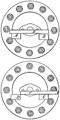
Fig. 2519.
The straight-edge should also be applied to test if the surfaces of the bars lead true one to the other; thus, in Fig. 2519, a and b are the bars and e the straight-edge, which by being pressed firmly to the surface of a discloses that the surface of a is not in line with b, because if it were so the straight-edge would meet the face of b as in Fig. 2519, where the straight-edge f pressed to the surface of c leads true to the surface of the bar d. All four of the bars require testing in this manner. If the seatings for the bars or the liners are not made flat and of equal thickness, or if from any other cause the bars do not bed properly upon the liners, then bolting up the bars will spring them as shown in Fig. 2520, in which, at a, is shown a bar sprung in the bolting up, because the liners fit at the ends b c only; while at e is shown a bar sprung or bent because the liners fit at the ends d d only. In either case the cross head would be forced to travel in a curve, bending the piston rod, and inducing much friction. The way to test the bars in this respect is, after the above operations, and before loosening the bolts, place a long straight-edge lengthwise along each bar and move it laterally at one end. If it swings from the centre the bar is rounding, while if it shuffles across first at one end and then at the other the bar is hollow in its length and we must find at which end of the bar this spring exists. To do this, slightly slacken the bolt or bolts at one end and again apply the straight-edge, if the spring is removed the error lies in the bedding of the liner at that end. If not removed, retighten the bolts at that end and slacken those or that at the other end, and again apply the straight-edge, and thus may it be determined how much of the spring is due to each of the liners, and this must be remembered and allowed for in filing the liner to its final adjustment. Before putting the liners in a second time it is better to give them a light coat of marking to show where they bear. At each trial of the bars the spirit-level and straight-edge should be applied and the cross head should be moved back and forth to show by the bearing marks how the cross-head guides fit to the bars. These marks are a great deal finer test than any spirit-level adjustment, hence the last part of the fitting should be performed with strict reference to the bearing marks upon both the bars and the cross-head guides as well as upon the liner, the cross-head flanges being adjusted and fitted at the same time as the face fitting.
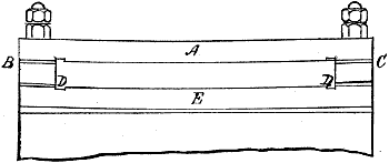
Fig. 2520.
To set the top bars place the cross head in the middle of its stroke, and place them upon the cross-head guides. Then, with the wedges applied as before, ascertain the required thickness of the respective liners one at a time, leaving them, as previously, a trifle too thick, and testing them while fitting by marking placed upon their faces. The top bars may be entirely adjusted from the contact marks left by the cross-head guides when moved along the bars, thus dispensing with the use of the straight-edge and spirit-level.
As the bolts supporting the bottom bars often require to be loosened to get the top bars off, pieces of wood may be placed beneath the bottom bars to retain them in position when the bolts are loosened. These pieces must be removed during the testing, for if left so as to wedge the bars they may spring them, and thus mislead in the adjustment. After the top bars are adjusted the whole bearing surfaces should be oiled, and the cross head pulled back and forth by hand without the use of a lever, providing the size of the piston does not exceed about eighteen inches diameter. The bars when set true should be clamped to their seatings and the holes reamed out to receive the proper bolts, and, finally, mark each bolt, bar, and liner to its place.
When the bars, tested with the straight-edge and spirit-level as described, show true, if the gland will pass freely in and out of the stuffing box with the cross head at any part of its stroke, the guide bars are set.
In this operation let it be noted that the close fit of the piston to the cylinder bore and of the gland to the stuffing box is alone depended upon as a guide whereby to so set the guide bars that the axial line of the piston rod and its plane of motion shall be in line with the centre of the crank shaft.

Fig. 2521.
Suppose, however, that the piston head is a new one, and the gland is worn a loose fit to the stuffing box, then setting the bar to the gland would produce the result shown in Fig. 2521, in which the dotted line a a is a line or cord stretched axially true with the cylinder bore, and coincident with the centre of the pillow block at b. The gland being a loose fit permits the piston rod to fall below its proper level, and the surface of the bars, if set by the gland only, without using the spirit-level, would be set true to the full line c c, and therefore out of true line. If the bars are set by spirit-level true to the length of the cylinder bore, the gland becomes useless as a guide to set the bars by. It is a not uncommon practice, when the gland has play, to insert in the stuffing-box bore, at the bottom, a piece of tin or sheet brass, equal in thickness to one-half the amount to which the gland is too small, or to insert a similar piece beneath the piston head if it is too small. As a rule, however, there will be at least as much play between the piston rod and the gland bore as between the gland and the stuffing-box bore; hence, if there is any play, it is better to discard the use of the gland altogether.
The proper method of setting guide bars by a stretched line is as follows:—
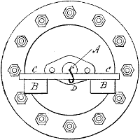
Fig. 2522.
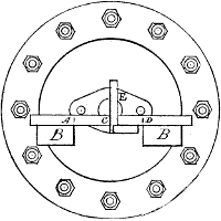
Fig. 2523.
The cord or line is set true to the cylinder bore, and coincident with the centre of the pillow block, as at a a in Fig. 2521, and the two bottom bars are put up in line horizontally with the axial line of the crank shaft, and at a distance below the stretched line equal to one-half the height of the guides for the cross head, as in Fig. 2522, in which a represents the stretched line, b, b the bottom bars, c c a straight-edge, and d a piece of wire whose length from point to point is equal to one-half the height or thickness of the guide blocks. The width apart of the bars is set to suit the width apart of the flanges of the guide blocks on the cross head, by means of a square. The square is applied in the following manner: On a straight-edge mark two lines a and d, Fig. 2523, a distance apart equal to the distance between the flange edges of the cross-head guides. Midway between a and d mark the line c; place the straight-edge across the bars as shown, and when the edge of a square, placed on the straight-edge, coincides with c and the stretched line, and the marks a and d coincide with the edges of the bars, the latter are set true, and will come right for distance apart, and distance from the centre line, supposing the flange edges of the cross-head guides to be equidistant from the centre of the length of the cross-head journal. If, however, such is not the case, the width from a to c and from c to d must be made to suit, c representing the centre of the length of the cross head journal, d the flange on one guide and a the flange on the other guide. Here it may also be remarked that, if the thicknesses of the cross-head guides vary, or if they are not central to the axial line of the cross-head journal, the bars must be set for distance from a in Fig. 2523, to suit the error, because in that figure the straight-edge is supposed to stand parallel to the axial line of the shaft, as it is also in Fig. 2522, the aim in both cases being to so set the bars that the cross-head journal shall stand parallel with the crank shaft.
It is the liability of variation in the thickness of the guide blocks, and of their not being central to the cross-head journal, that constitutes the disadvantage of setting the bars by lines, it being obvious that the bars must be either set to suit any errors in the guides, or those errors must be eliminated before setting the bars. The top bars must be set parallel to the bottom ones, at a distance from the bottom ones equal to the thickness of the guide blocks, and parallel to one another. It is preferable to set the top ones with the cross head and guides in place, observing all the precautions as to springing them given in the case of the bottom bars.

Fig. 2524.
The bars thus set will be in line with the crank axle, but unless the piston accurately fits the cylinder bore, they will not long remain in line with the line of motion of the piston rod. For example, Fig. 2524 shows a piston head too small for the cylinder bore, the guides fitting the bars properly, and the gland and stuffing box fitting the piston rod; the piston will be suspended in the cylinder, its overhanging weight being supported by the guides b, the gland, and packing ring. This would cause friction and rapid wear of the gland bore and guide surfaces in a direction parallel to the line c, which would gradually let the piston fall to the bottom of the cylinder bore, touching at the end of d first. In some engines provision is made to adjust the piston to take up its wear, which is, it will be seen, a great advantage.
The Heating and Pounding, or Knocking, of Engines.—The heating of any part of an engine occurs from one of two causes, viz., either the fit of the parts is too close, inducing undue friction, or the parts are not in line.
When the former is the cause the remedy is to ease the fit. If the parts are not in line, the heating may also be remedied by loosening the fit of the parts; but this will often induce a pound or knock, hence the true remedy is to properly align the parts.
The location of a pound may be discovered by placing a piece of metal wire between the teeth, and resting the other end of the wire upon each end of the cylinder, guide bars, and bearings of the main shaft, repeating the operation in each place, and the sense of feeling will distinctly indicate the location of the knock, by imparting a more severe shock to the teeth when the vicinity of the knock is approached.
The most prominent location of the causes of a pound are, first, in the crank pin, from causes to be hereafter explained, and from its wearing oval at the cross-head journal; and second, at the ends of the cylinders, or the ends of the guide bars, because of a ridge forming there as the wear proceeds.
A crank pin cannot wear oval if the brasses are kept adjusted to fit it, because in that case the brass bore must wear it round; but if there is any play it wears oval, because the pressure of contact between the journal and the brass bores is least when the pin is at and near the points of dead centre, and the most when it is at and near half stroke.
The cross-head pin wears oval because the pressure between the pin and its bearing is in a line with the connecting rod, and there is but little wear on the pin in a direction at right angles to the rod.
Ridges form at the ends of the cylinder bore and at the ends of the guides for the following reasons:—
Referring to the cylinder, the location of the piston stroke in the cylinder bore alters as the connecting-rod keys pass through the rod, because that alters the length of the connecting rod, and therefore the path of the cross-head guides on the guide bars, and also that of the piston in the cylinder.
As the piston rod is shortened there is less wear at the extreme end of the cylinder bore farthest from the crank, and the same remark applies to the guide bars.
If the piston head travels past the end of the cylinder bore and into the counterbore at each end, a distance equal to the amount of taper on the connecting-rod keys, or equal to the amount the connecting-rod length will alter while those keys are passed through the rod (to take up the journal and brass wear), the piston head will (if the rod is kept to its original length within that amount) always travel to the end of the cylinder bore, and no ridge should form on account of the length of the rod altering; but even then a slight ridge may form because the wear is naturally less at the ends. Thus in the middle of the cylinder length the whole thickness of the piston head, piston rings, and of the follower passes over the bore, while at the ends only the flange of the piston head at one end and the follower at the other passes over the metal of the bore; hence the friction and wear are less.
The ordinary cause of pounding and heating is a want of truth in the alignment of the crank pin, or in that of the cylinder, main shaft, or guide bars.
The method to be employed to line an engine, or to discover if it is out of line, depends upon the design of the engine and its condition; thus an engine having a Corliss frame has the slides to receive the cross head made at a true right angle to the end face which meets the cylinder end; equidistant from the centre of the gland hole or axis of the piston rod, and the end of the frame fitting either the bore of the piston or the turned flange of the cylinder cover; hence the guide bars must be true if the frame is got up true, the fit of the frame end to the cylinder end insuring truth in the guide or cross-head slides, providing that the centre line of the frame, during the turning and planing operations, leads from the centre of the cylinder end of the frame to the centre of the crank-shaft brass; or, in other words, the planing and boring of the frame must be true with a line running from the centre of the cylinder end of frame to the centre of location for the crank shaft. This will not only cause the outside of the frame casting to stand at its proper level when the cylinder bore stands horizontally level; but it will insure that the crank-shaft bearing brasses both be of equal and of a proper thickness through the crown.
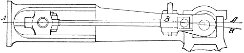
Fig. 2525.
The engine being properly lined at first will not be liable to get out of line, excepting so far as affected by the wear of the crank-shaft bearing, which will cause the crank shaft to drop, as shown in Fig. 2525, where a a represents the true centre line of the cylinder and guide bars, which, when the crank is in the position shown in the cut, should be coincident with the centre line of the connecting rod and the crank, but the crank brass having worn below the centre line of the connecting rod and crank, the crank will get out of line as denoted by the line b b.
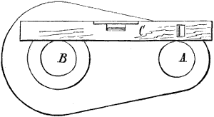
Fig. 2526.
As a result, a portion of the piston movement and pressure which should be exerted on the crank after leaving the dead centre, will be exerted on it before it reaches the dead centre, thus causing a back pressure, involving a loss of power. Furthermore, the relative position of the eccentric to the valve gear will be altered, impairing the proper set of the valves; hence it follows that the wear of the crank bearing in this direction should be taken up (by raising the lower brass) before it becomes excessive. To find how much the bottom brass requires raising, or whether it requires raising or not, find the centre of the crank shaft, and from this centre strike the circle b, in Fig. 2526, whose diameter must equal that of the crank pin a, and place the edge of a spirit-level coincident with the perimeters of the crank pin and circle, as shown in the cut. When the bubble of the spirit-level stands in the same position as it does when the level is placed upon the bore of the cylinder or along the piston rod, the crank will be in line with the cylinder bore.
As a rule, the cylinder bore of a horizontal engine stands horizontally true, and the crank centre line should also stand so when the crank is on its dead centre, but if such is not the case the crank centre line must nevertheless stand true with the axial line of the cylinder, when the crank is on the dead centre.
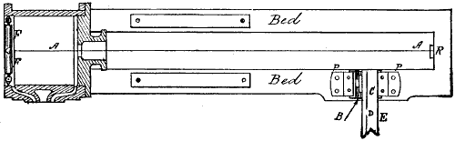
Fig. 2527.
If, instead of having a Corliss frame and fixed guide bars, the engine has a flat bed and adjustable guide bars, as shown in Fig. 2527, the operation is as follows:—
In setting up a new engine it is obvious that if the flanges of the cylinder are planed parallel with its bore and at the proper distance from its axial line, and the pillow block is made of the proper height, a line stretched axially true with the cylinder bore will pass through the centre of bore of pillow-block brasses, or be equal in height from the engine bed; but the length of the cylinder being only about one-fifth of the distance from the cylinder to the centre of pillow block, any error in the planing of the cylinder flange true to the cylinder bore becomes magnified five times at the pillow block; hence it is necessary to stretch a line through the cylinder bore and set the cylinder so that the line, being axially true with its bore, will pass the pillow block at the centre of the bore of its brasses. This is sometimes done by inserting thin pieces of sheet tin, metal, or even paper beneath the cylinder flanges and the bed, and in the requisite positions. The method of stretching the line is shown in Fig. 2527. f is a device for holding the line at that end. It consists of a frame in the form of a cross, with adjusting screws at the end of each arm, and a small hole at its centre to receive the line. The other end of the line a must be secured, under as much tension as the line will safely bear, to a piece of wood clamped to the engine frame at r. The adjustment of the line is made by measuring its distance from the walls of the bore of the cylinder at one end and of the bore of the gland hole at the other end, using a pair of inside calipers or a wire gauge. The latter should be bent in its length to admit of adjusting the same by straightening to increase, or still further bending to diminish, its length to suit the requirements.
The wire, when applied, should only just meet or touch the line and not bear the least hard, or it will spring the line, causing an error of adjustment that will be serious when multiplied by the length of the line to the pillow block as compared with the length of the cylinder bore.
If the pillow block is planed on its bottom face and has its brasses fitted, the latter may be marked off for boring from the line a, Fig. 2527, when stretched to set the cylinder, thus avoiding a second adjustment of the line a a.
Suppose now that it is required to line the brasses in the pillow blocks true to be bored (the pillow blocks being bolted in position). The distance of the face p, of the brass from the stretched line a, in Fig. 2527, must equal the distance from the centre of the length of the crank-pin journal, to the face of the large crank hub, and this distance may be shown by a line marked on the edge of the brass flange.
Place a straight-edge c, Fig. 2527, having a line d parallel with its edge e, so that this line will be in the centre of the width of the pillow-block jaws, and at a right angle to the line a. The line d will then represent the axial line of the crank shaft, and may be used as the centre from which to mark the lines on the brasses used to set them by for boring. To test if a and d are at a right angle, or to set d to a, a large square should be used. If the side face p p of the pillow block stands parallel to a, as it should do when it is true, it will serve to chuck the pillow block by, thus boring the brasses in their places in the pillow block, with the centre line of the bore at a right angle to p. If otherwise, two flat places should be filed on the brasses, as shown in Fig. 2528, in which c is the straight-edge, and a the stretched line as before, h and i representing the flat places whose distance from a, as shown at j j, may be made to represent the thickness of the crank from its large hub face to the centre of length of crank-pin journal; hence the depth of the flat places will show how much to take off the face of the brass to leave it of the proper thickness.
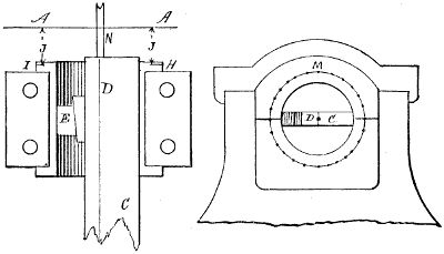
Fig. 2528.
A straight-edge placed across these flat places, or true to the lines h i, must stand at a right angle to the line d, so that by setting the brasses by the flat places they will be bored to stand at a right angle to a. To set the brasses the other way a circle is struck from d, as a centre, upon the faces of the brasses as in the end view, Fig. 2528, in which the straight-edge c is shown wedged in the bore of the brasses, which is the most convenient way when it can be done.
The line d is carried down on the end face of the straight-edge, and the latter is used as a support for the compass points while striking the circle m, which is defined more clearly by indenting it with fine centre-punch marks. The height of the centre for bore of brasses may be carried from the centre line of the cylinder a a to the end of the straight-edge c, by placing another straight-edge across the engine bed and measuring from the end of c to a.
Suppose now that the brasses are bored, and the position of the pillow block is to be set, and the process is the same, the line d being marked true from the bore of the brasses, and the pillow blocks adjusted until d is at a right angle to line a a.
Though in a new engine every part may be made as true as possible in the details of manufacture, yet when the parts come to be put together errors of alignment will generally be found to exist. These errors may be too minute for discovery in the separate piece, and yet form important defects in the finished engine.
In rough practice these defects are left to remove themselves by abrasion and wear, the process being to allow the parts to be somewhat loose (wherever possible) in their adjustment, and adjust them closer as the abrasion proceeds.
This is termed letting the parts wear down to a bearing. But the very process of wearing down to a bearing attests that the parts have not been properly fitted to a bearing, whereas to attain the best possible results the parts should be fitted to a bearing, because in wearing down to a bearing, undue abrasion, and to some extent or in some degree, roughness of the wearing surfaces, must ensue, because the strain intended to be distributed over the whole intended bearing area is limited to the actual bearing area. It is necessary, therefore, that, in putting an engine together, each part be properly fitted to its place, and that it be subsequently adjusted in its fit and position with relation to the other parts to which it is connected.
The fitting of the single piece is a test of its individual or disconnected truth; the subsequent or second adjustment is a test of its truth with relation to the others. Thus a pair of brasses may fit a journal perfectly, but that is no assurance that the brasses are so bored as to bring the rod holding them in proper line to enable connection at the other end without springing or bending the rod.
Furthermore, it often happens that the frame work of an engine does not form a base for the whole of the parts, thus in a large stationary engine, the end of the main shaft or crank shaft farthest from the crank (generally called the outboard bearing) is generally supported by a bearing having an independent foundation, and as this foundation does not exist until the engine comes to be permanently fixed for operation, its alignment must be performed when setting the engine. In an old engine this foundation may settle, or the wear itself may throw the engine out of line, so that the lining of an engine becomes periodically a necessity.
As a general rule a want of alignment induced by wear or incurred from repairs to the parts principally affects the main shaft, the cross head remaining more nearly true; and, with the exception of the crank pin, the same holds good with reference to a new engine.
Now while an error of alignment may exist in any direction, it is true, nevertheless, that an error in any direction will be discoverable if the parts be tested at four equidistant parts of the stroke or revolution, as, for instance, on the two dead centres of the crank and at the highest and lowest points of the path of rotation of the crank pin; hence attention may be confined to those four points.
Suppose then an engine already put together requires to be tested for being in line, and we have to test—
1st. The alignment of the main or crank shaft vertically.
2nd. The alignment of the main shaft horizontally.
3rd. The axial truth of the crank pin with the main or crank shaft.
4th. The adjustment of the crank shaft for vertical height, with relation to the cross-head journal.
Referring to this last, it may be necessary to remark that the axial line of the main shaft may be parallel when viewed either vertically or horizontally with the cross-head journal, and yet if a line be passed through the centre of the cylinder bore, and prolonged past the crank centre, the latter may fall above or below that line, but it will generally be below, because from the weight of the crank shaft its bottom bearings wear the most; and, further, to whatever extent those bearings wear after being in proper line, the crank shaft will fall too low.
We may now subdivide the errors of alignment of a crank shaft thus:—
1st. Its axial line, when viewed vertically, may form an acute angle to the axial line of the cross-head journal.
2nd. It may form an obtuse angle with the cross-head journal when so viewed.
3rd. It may, when viewed from the crank-pin end of the engine on about a horizontal position, be too high or too low at the crank-pin end only.
4th. It may be too high or too low at the outboard end only.
5th. It may be too high or too low at both ends, although parallel to the cross-head journals.
It will be found on consideration that with the exception of the last-named case, the connecting rod forms the best test whereby to discover an error in any of these directions, because it magnifies the error and makes it more plainly discernible. It will further be found upon careful observation, that although a combination of these errors may exist, the connecting rod will serve to discover each error separately, as well as the collective error, because, although in some respects two distinct errors may have the same general result, yet the result will be different if taken in detail, and it follows, therefore, that the testing must be taken or made in detail first.
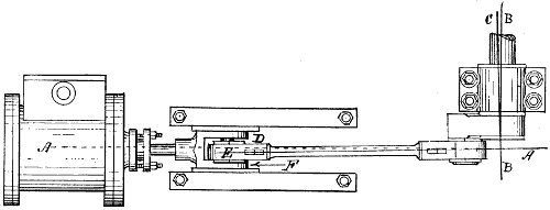
Fig. 2529.
To test the parallelism of the axial line of the crank shaft with that of the cross-head journal, when viewed vertically: In Fig. 2529, let a a represent a line true axially with the bore of the cylinder, and b b a line at a right angle to a a, and passing through the centre of the pillow block or bearing spaces. If the engine were in line, b b would be coincident with the axial line of the crank. Suppose, however, that line b c represents the actual centre line of the crank, not then being at right angles to a, the end e of the connecting rod, if connected to the crank pin as shown, and made a good working fit so that there is no play of the pin in the brasses, will not come fair laterally with the bearing in the cross head. The amount of the error is the amount it is out of true in the length of the crank-pin journal, multiplied by the product of the length of the connecting rod (from centre to centre of the bores of the brasses) divided by the length of the crank-pin journal. It is apparent, however, that if the crank shaft be set to have its axial line at b b instead of at b c, the error at e d will be corrected, and thus we may employ the connecting rod to set the crank shaft in line.
It is, however, not sufficient to try the crank on one dead centre only (as will be seen presently), hence we place it on the other, and move the cross head to the other end of its stroke, and again try the end e of the connecting rod with the cross-head journal, and if it falls to one side, and on the same side as before, but to a less amount, it demonstrates that the axial line of the crank forms with the line a a an acute angle. If, however, instead of falling too much laterally towards the side f of the cross head, it fell too much towards d, but more so when tried with the crank on the dead centre nearest to the cylinder than when tried with the crank on the other dead centre, then it is proof that the axial line of the crank shaft forms with a a an obtuse angle.
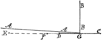
Fig. 2530.
The reason that the error will be more plainly shown with the crank on one dead centre than when on the other is shown in Fig. 2530, in which a a is a line coincident with the axial line of the cylinder bore, and b b the axial line of the crank shaft, from c to d is the plane of revolution of the crank pin, while g represents the crank centre. The points at c and f denote points central to the length and diameter of the crank-pin journal. Now, the centre line of the connecting rod for one dead centre is represented by e d, and for the other by f c, and it will be seen that the point at e is farther from a than is the point at f. It will be observed that the point d falls outside, while the point c falls inside of a a, and yet the centre line of the connecting rod stands, in both cases, at the same angle to the centre line a a of the engine, and in both cases throwing the end of the connecting rod, represented by the points at e f, outside the line a a.
If the connecting rod does not, when connected to the engine, as in Fig. 2529, fall true into the cross-head bearing, the error is the same in amount and comes on the outside of the cross-head journal with the crank placed on each respective dead centre, it is proof that either the flange of the crank-shaft brass (which is between the crank face and the frame) is too thick, or the inside flange of the connecting-rod on the crank pin is too thick, or else the crank is too thick, measured from the crank-pin journal to its inside hub face, the error being in the new crank or new brass, if one has been put in.
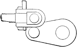
Fig. 2531.
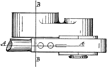
Fig. 2532.
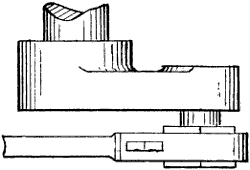
Fig. 2533.
It may here be remarked that if the bore of the crank-pin brasses of the connecting rod is not at right angles to the centre line of the rod itself, the end e, Fig. 2529, might fall either inside or outside, laterally, of the cross-head bearing, but in this case the error will show more at one end of the stroke than at the other, for reasons which are explained with reference to Fig. 2530; hence it follows that the connecting-rod brasses should be properly fitted to their journals, and made to lead true before using the rod to line the engine by. In some cases it is more convenient to connect the rod at the cross-head end, and try the other end with the crank-pin journal, as shown in Fig. 2531. In this case, however, the connecting rod will (whenever the axial line of the crank shaft is out of square, forming an acute angle with the centre line a a, as in Figs. 2529 and 2530), fall laterally inside the crank-pin journal when on one dead centre, as in Fig. 2531, and outside when on the other dead centre, as in Fig. 2532, the respective amounts of error being in this case equal for the two positions. The reason for this is that the plane of revolution of the crank pin falls outside of the centre line in one case, and inside for the other, as shown in Fig. 2530 at d c.
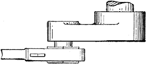
Fig. 2534.
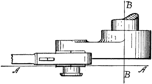
Fig. 2535.
If the axis of the crank axle formed an obtuse angle to the engine centre line a a in Fig. 2529, the connecting-rod end tried with the crank pin, as shown in Fig. 2531, would fall outside of the crank-pin journal when the latter was on the dead centre nearest to the cylinder, as shown in Fig. 2534, and inside of the crank-pin journal when on the other dead centre, as in Fig. 2535.
Now, suppose either of the errors to exist, and the alignment be neglected, then if the brasses at each end be keyed up to fit their respective journals, then the body of the rod must be bent into a bow shape, and the strain of forcing or springing it into this shape will fall upon the journals, which will heat and pound in consequence.
It is now to be explained how to test if the axial line of the crank shaft is at a right angle to that of the cross-head journal, when viewed from the crank-shaft end and horizontally.
From a want of parallelism in this direction, heating of the crank pin and cross-head journals is sure, and a pound or thump is, to some extent, liable to occur, and the cause, if the error is slight, is difficult to discover, save by using the connecting rod to test it with.
When a thump occurs at the end of the stroke (when the crank is on a dead centre), it may arise from a ridge at the cylinder, or at the guide-bar end, or from the connecting-rod brasses being insufficiently keyed up; but when it occurs while the crank is at half stroke these causes are eliminated, and the cause must be looked for in either a crank pin not parallel to the crank shaft, or, as in the case now under consideration, because of one or the other of the crank-shaft journals being too low.
Assuming the crank pin and crank shaft to be axially true, one with the other, we may proceed to show separately the cause of the heating and that of the pounding, if the crank journal is too low at either end.
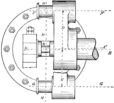
Fig. 2536.
In Fig. 2536, let a represent the cross-head journal, and b b a line parallel to it. Let b c represent the axial line of the crank shaft (being out of parallel because the crank end is too high or the other end too low). Let f f represent the centre line of the crank pin when at the top, and g g when at the bottom of its path of rotation, and it will be observed that the vertical distance between the crank pin and the axial line of the cross-head journal is less on one side than on the other; thus in the figure distance d is less than e. We have in this case measured these distances on a plane at a right angle to the cross-head journal, but it will make no difference if we measure them on a plane with the path of rotation of the crank pin, as will be seen in Fig. 2537, in which the distance from the centre of the crank pin at two opposite points in its path is represented by dots shown at e f, and from e to h measures less than from f to h, h representing the centre of the cross-head journal.
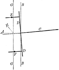
Fig. 2537.
In Fig. 2537, let a represent the axial line of the cross-head journal, b a vertical line at a right angle to a; c representing the crank shaft extended by a dotted line, so as to enable comparison with a; d the crank, e and f the centre of the crank-pin journal, and g g a line at a right angle to cross-head journal a.
Now g, being at a right angle to a, represents what should be the plane of rotation of the crank pin, whereas c, being out of parallel with a, causes the path of rotation to be in the path from e to f, or as d compared to b; supposing then that the bores of the connecting-rod brasses to be axially parallel one to the other, and keyed up properly, and when at e one bore of those brasses will stand parallel to e while the other is parallel to a, or when at the bottom of the crank rotation, one bore will be parallel to f and the other parallel to a. Thus the rod will be twisted, and the strain due to this twist will cause the bearings to heat. That this twisting is continuous throughout the whole revolution may be seen by the want of parallelism of the dotted line (representing the crank pin when on the dead centre) with a (representing the cross-head journal).
It is now to be observed that if the plane of the crank rotation were at a right angle to the axis of the cross head, as it should be, the path of the centre of the crank-pin journal would be in the plane of g g, whereas it falls outside as at e, and inside as at f, while at h it is coincident; hence it appears that starting from a dead centre h, the rod bends, passing at that end outward to e (when the crank has made a quarter revolution), where it attains its maximum bend, thence diminishing until finally ceasing, when the crank reaches the other dead centre. As soon, however, as it passes the last dead centre a bend in the opposite direction takes place, attaining its maximum at f, and ceasing at h. This bending also causes undue friction and the consequent heating of the journals; furthermore, if there be any end play between the brasses and the journals, there will be a pound, as the brasses jump from one end of the journal to the other at different parts of the stroke. It is obvious that if the crank end of the crank shaft was too high instead of too low, as in our example, then the effects would be the same, but e would fall on the inside instead of the outside of g, while f would fall outside instead of inside.
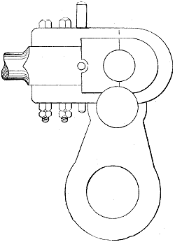
Fig. 2538.
To discover if the crank shaft is out of parallel in the direction here referred to, connect the connecting rod to the cross-head journal, setting the brasses up to a close working fit. At the other end of the connecting rod put the strap keys and brasses in their places, but not on the crank-pin journal. Place the crank in its highest position, and lower the end of the rod down to the crank-pin journal, as shown in Fig. 2538, and if the crank shaft is parallel (in the respect here referred to) to the cross-head journal, the brass flanges will just meet the faces of the crank-pin journal, as shown in Fig. 2539. If, however, the crank end of the crank shaft is too low, as in our example, the flanges of the brasses will fall to one side of the crank-pin journal, and that side will be toward b, Fig. 2540, when the crank pin is at the top, and toward c, Fig. 2541, when it is at the bottom of its path of rotation.
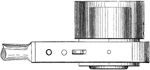
Fig. 2539.
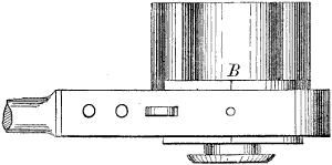
Fig. 2540.
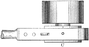
Fig. 2541.
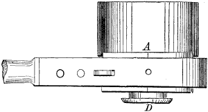
Fig. 2542.
The effects will be precisely the same, and in the same direction with relation to the various parts of the crank’s revolution, if the crank-pin end of the shaft was of correct height; but the other end was too high, hence, in correcting the error, it is desirable to place the engine on the dead centre, so as to determine which end of the shaft to operate on—that is to say, whether to raise the crank-pin end or lower the other end. But suppose the error to be that the crank-pin end of the shaft was too high instead of too low, then, the testing being continued as before, the effects will be of the same general character, but altered with relation to the specific parts of the revolution. Thus, when the crank is at the bottom, the rod would fall towards a, Fig. 2542, and when at the top, it would fall in the opposite direction—that is, towards d, Fig. 2542.
We now come to one of the most common errors in the alignment of the parts of an engine, and to the one that it is the most difficult to locate or discover, namely, a want of parallelism between the axial line of the crank pin and that of the crank shaft.
This generally arises from improper methods in the chucking of the crank to bore it, or from errors induced in fastening the crank to its shaft. The results are precisely alike in both cases, supposing, of course, the errors to exist in the same direction in the two cases.
The error in chucking usually consists in planing one surface of the crank, and bolting the planed surface against the chuck to bore both crank holes. In this case the crank holes will be out of true to twice the amount the lathe face plate may be out of true, and to whatever amount the crank may alter its form from having its surface metal removed.
To avoid these errors the large bore and its hub face should be turned at one chucking, and this hub face should be bolted to the face plate for the second chucking, the small end swinging free, except in so far as the ends of the plates may touch against it to steady it.
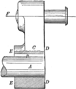
Fig. 2543.
The error in putting the crank on may occur from the key springing the crank out of true, and if the crank is shrunk on from too great an allowance for shrinkage or improper heating for the shrinkage or contraction, as it is sometimes termed. Referring to the error in keying, it is more liable to occur when the crank bore and its seat upon the shaft are made taper, than when made parallel, because it is a difficult matter to insure accuracy in the fit of the taper, and the key pressure will spring the crank over on the side at which it is the easiest fit. In Fig. 2543 let a represent the end of the crank shaft; b the key, and c the crank shown partly in section: suppose the crank bore (whether made taper or parallel) has a slightly easier fit on the side d than on the side e, and the pressure of the key (supposing it to fit properly top and bottom) would spring the crank over in the direction shown in the figure, the axial line of the crank pin standing at the angle denoted by the line f, instead of parallel to the axial line of the shaft. Suppose the crank to be put on by hydraulic pressure, and the key to fit on the sides and not on the top and bottom, then its fit to its seat on the shaft would depend on the truth and smoothness of its bore and seat on the shaft, the amount allowed for the forcing fit and the amount of the error. If the latter amount was so small that the crank would fit at both ends, but simply fit tighter at e e than at d, the crank would remain true, but might possibly get loose in time. This would be especially liable to occur if the tool marks on the bore and seat were so deep that the contact was mainly at the tops of those marks or ridges which would be apt to compress. But if the surfaces were cylindrically true and smooth, and the amount allowed for forcing was sufficient as stated to give the bore and seat contact at d, with a key fitting sideways, the crank would probably remain tight and true.
Were the bore and its seat parallel the crank would remain true, no matter whether the key fitted on the sides or at the top and bottom, providing the key fitting top and bottom were bedded fairly from end to end.
When the surfaces are not smooth, but contain tool marks or ridges, an unequal pressure of the key at one end, as compared to the other, sets the crank over, as shown in the figure, because the key pressure compresses the ridges and lets the crank move over.
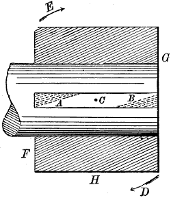
Fig. 2544.
Supposing the strain of the key, or keys, to be depended upon to hold the crank, they must fit top and bottom, and their accurate fit becomes of the first importance; because not only is it necessary that they fit equally at each end, but they must also fit equally across the width of the key at each end. For example, in Fig. 2544 is a key binding most at the opposite corners, as denoted by the dotted surfaces a b, and the result will be that the key pressure would tend to twist the crank in the direction of d e, having c as a centre of motion, providing that the error was equal at a and b; but in proportion as the error was greatest and the fit tightest at a, or at b, would the centre of motion be moved nearer to either point.
Supposing now that the crank is to be shrunk, or contracted on, then the points of consideration are (supposing the crank to fit properly to its seat, whether the same be either parallel or taper) that the hub of the crank opposite to the throw is the weakest and is likely to give most in the process of contraction, so that if one part (as f) of the crank be made hotter than another (as g) it will give way more, and this will twist the crank. This is specially liable to occur if an excessive amount of difference in the bore and seat diameters has been allowed for contraction.
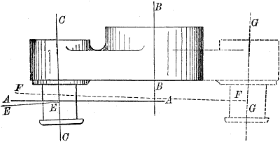
Fig. 2545.
It may not happen that a crank pin is out of truth in a direction in which the error will show plainest when the crank is on its dead centres, or at half-stroke; but if a crank pin, tested in those four positions, fails to show any error when tested by the connecting rod, it will be true enough for all practical purposes, and true enough to avoid heating and pounding, both of which evils accompany an untrue crank pin. Suppose, now, that a crank pin stands out of true in the direction shown in Fig. 2545, in which a a represents the axial line of the cylinder bore prolonged, and b b the axial line of the crank shaft (the two being parallel or in proper line). Let e e represent the centre line of the connecting rod when the crank is on one dead centre, the axial line of the crank pin being at c c. Then the brasses being keyed up to fit the crank pin, the centre or axial line of the connecting rod would stand as denoted by e e. But the brasses at the other end of the rod being keyed up to fit the cross-head journal, and their lines being at a right angle to the line a a, we have that the rod is at that end endeavored to be held parallel to a a; hence, keying up the connecting-rod brasses on the crank pin would tend to bind the rod, one end standing parallel to a a, and the other parallel to e e.
This would place great strain on the outer radial face of the cross-head journal, as well as on the cylindrical body of the journal.
When, however, the crank pin arrives at the opposite dead centre, as denoted by the dotted lines in Fig. 2545 (g g representing its axial line, and f f the centre line of the connecting rod at a right angle to g g), the want of truth in the pin throws the cross-head end of the connecting rod against the inside face of the cross-head journal. Hence, twice in each revolution is the connecting rod bent, and twice does it jam from side to side of the cross-head journal.
It may now be pointed out that if we take either dead centre singly, and connecting the rod at the crank-pin end, try it at the cross-head end, and it will be a difficult matter to determine whether any want of truth at the latter end is caused by the crank pin being out of axial truth, or whether it is the crank shaft itself that is out of line. But there is this difference between the two cases. When the error is due to want of alignment in the crank shaft, the connecting rod will show the error on the same side of the cross head, no matter on which dead centre the crank pin stands; but when it is due to the crank pin, the rod will fall inside the cross head on one dead centre, and outside when tried on the other dead centre, as is shown by the respective lines e and f, in Fig. 2545; e being at a right angle to c, and f at a right angle to g.
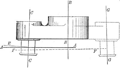
Fig. 2546.
Again, it has been shown that when the shaft was out of line, a point on the crank-pin journal passed outside of the cylinder centre line at one dead centre and inside at the other; but when the pin is axially out of parallel, the path of a point on its journal will remain in the true plane, as is shown in Fig. 2546, the point being taken at the intersection of e and c c. a a represents the path of rotation of the same, which is parallel to the true face b of the crank.
From the angle of the axial line of the pin being in opposite directions, when on opposite dead centres to the axial line of the crank shaft, the bore of the brasses cannot wear to suit the error, which, therefore, only diminishes by the wear of the crank pin. Suppose the error to be 1⁄64 inch in a crank-pin journal 3 inches long, and that the connecting rod is 6 feet long, the error at the cross-head end of the rod will amount to 3⁄8 inch.
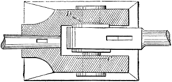
Fig. 2547.
In Fig. 2546 the error is shown to exist in an opposite direction, throwing the rod to the other side of the cross-head journal. But, in this case, the crank, when on the dead centre nearest to the engine cylinder, throws the connecting-rod end against the inside face of the cross-head journal, as denoted by the line e, which is on the opposite side of a a to what it is in Fig. 2545. Again, when on the other dead centre, the line f f, in Fig. 2546, falls outside, while f f, in Fig. 2545, falls inside of a a, and it is by this difference that we are enabled to know in which direction the crank pin is out of true. To find the amount to which it is out of true in the length of its journal, place the crank on one dead centre, and with the connecting-rod brasses keyed up firmly home on the crank pin, and the other end of the connecting rod entirely disconnected from the cross head, mark on the latter a line coincident with the side face of the rod end, as at d, Fig. 2547. Then, with the crank pin placed on the other dead centre, mark another line on the cross head, coincident with the other side face of the rod, at c, Fig. 2547. Now, suppose that the line d shows the rod to fall 3⁄8 too much on that side, and line c shows it to fall (when on the other dead centre) 3⁄8 too much on the other side of the journal, and that the length of the rod is 6 feet, while that of the crank-pin journal is 3 inches, then the latter, divided into the former, gives 24, and this sum divided into the 3⁄8, the rod end falling out of true at c and d, Fig. 2547, gives us 1⁄64-inch as the amount the crank pin stands out of true in its length; hence, to correct the error, we may file on the crank pin a flat place at each end, as shown in Fig. 2548 by the lines c d, and then file on the top and the bottom of the crank pin a flat place b, 1⁄128-inch deep, and of equal depth all along the journal; by then filing the crank pin round and bringing the flat places just up to a circle, we shall have reduced the diameter of the crank pin by 1⁄64 inch, and have made it axially true with the cross-head journal. It is important, however, to bear in mind that, in this case, the crank pin is supposed to be out of true in the direction shown in Fig. 2545, and to stand axially true with the cross-head journal, when the crank is placed at half stroke, top and bottom, the crank shaft being in proper line.
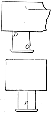
Fig. 2548.
If the axial line of the cross-head journal stands truly horizontal, the flat places on the crank pin may be filed horizontally level, with the crank placed on the corresponding and respective dead centres. But as the length of the cross-head journal is so short, it is difficult to gauge, if it does stand axially exactly horizontal, hence it is better to try the rod, or follow the above directions; especially as the cross-head journal and crank shaft may be in line without being axially horizontal.
Suppose now that the axial line of the crank pin stands true with that of the cross-head journal when the crank is on either dead centre, but out of true when at the top and bottom half stroke. The connecting rod, connected as before, and tried with the cross head, will fall first to one and then to the other side of the cross-head journal, and the direction in which the crank is out of true may be known from the position of the crank pin when the error shows itself.
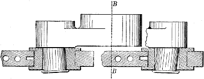
Fig. 2549.
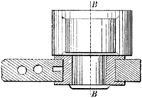
Fig. 2550.
If the error exists to an extent that is practically measurable, a pound in the journals, as well as their heating, is the inevitable result. In Fig. 2549, for example, the rod end is shown in section, and it will be noted that the error being in the direction there shown, and the crank pin in the respective positions there shown, the brass bore only contacts with the journal at each end, and that the diameter of the bore of the brasses is greater than the diameter of the crank pin journal to twice the amount the crank pin is out of line. Now let us place the crank at the top of its revolution, as in Fig. 2550, and as its axial line then stands parallel to that of the cross-head journal, the brass bore is too large to fit the crank pin journal and there is lost motion.
From the time the crank pin passes the dead centre this lost motion increases in amount until it becomes sufficiently great to slam the rod over against the side of the cross-head journal, while at the same instant the crank pin pounds in the connecting-rod brasses. At what precise part of each quarter crank revolution this action will occur, depends upon the amount the crank pin is out of line; but the more it is out the nearer to the dead centre it will be, and, conversely, the nearer true it is the nearer the crank will approach its highest and lowest positions before the pound takes place. If it is attempted to key up the brasses so as to spring the rod and let them close along the journal, the brasses will heat in proportion to the amount of error; hence when the crank pin pounds with the brass properly adjusted, and heats while keyed up enough to stop the pound, the crank pin is out of true.
To test the alignment of an engine with stretched lines take out the piston and rod, and take off the connecting rod, then fasten a piece of iron at the open end of the cylinder so that it will hold a stretched line true with the axis of the cylinder bore. Provide at the crank end of the engine bed a fixed piece of wood to hold the other end of the line, and then with a piece of wire as a gauge set this line (tightly stretched) true with the cylinder bore. Then place the crank pin at the top of its path of rotation and drop a plumb line from the centre of its journal length, and this line should, if the crank shaft is horizontally level, just meet the stretched line. If it does not do so place a spirit level on a parallel part of the crank shaft, and if the shaft is not level it should be made so, and so adjusted that the line from the centre of the length of the crank pin journal just meets the stretched line from the cylinder bore.
To test if the axial line of the crank shaft is at a right angle to the cylinder bore axis move the crank pin nearly to its dead centre, and measure the distance from the middle of its length to the stretched line. Then move the crank pin over to nearly the opposite dead centre, and (by means of the plumb line) measure the distance of the plumb line from the stretched line. To be correct the plumb line from the crank pin will during this movement just touch the stretched line.
To test if the stretched line is fair with the centre of the crank shaft place a square on the end of that shaft and even with its centre, and the blade should then just meet the stretched line.
The edges of the guide bars may also be tested with the stretched line, and the top and bottom of the guide-bar flanges may be tested to prove if the bars are of the correct height.
To further test the bars place a spirit-level across them and lengthwise on them.
If the piston rod and connecting rod are in place the alignment may be tested as follows; Let the piston rod be as far out of the cylinder as possible, and stretch a line to one side of it, just far enough off to clear the guide bars, &c. Set this line as follows: Let it be in line with the rod as sighted by the eye when standing some few feet away from it but horizontally level with the centre of the rod, set it parallel to the rod with a rule or its equivalent. Then the centre of the crank-pin journal should measure from the stretched line, the distance of the line from the piston rod added to half the diameter of that rod. This test, however, is not very accurate on account of the difficulty in setting the line, and because the piston rod may not have worn equally on each side.
Setting Slide-Valves—An engine slide-valve may be so set as to accomplish either one of three objects. First, to give equal lead for each stroke; second, to cause the live steam to be cut off and expansion to begin at an equal point in each stroke; and third, for the exhaust to begin at an equal point in each stroke.
If we, set the eccentric so that the exhaust will begin at corresponding points for the two strokes, the valve lead will not be equal, and the exhaust opening will be greater when the piston is at one end of the cylinder than it will be when the piston is at the other end.
If the eccentric be set to cut off the steam at corresponding points for the two strokes, then the lead, the admission, and the exhaust of the steam at one port will differ (with relation to the piston movement) from that at the other. It is generally preferred to set the eccentric so as to give equal lead for the two ports when the piston is at the respective ends of its stroke, which gives an equal amount of exhaust opening when the piston is at the respective ends of its stroke.
The only operations properly belonging to the setting of a slide-valve are those of finding the true dead centres of the crank pin, and setting the eccentric to give the valve the desired amount of lead. It is generally found, however, that the length of the eccentric rod requires a little correction, and as this must be done before the eccentric can be set, the setting operations should be conducted with a view to making the correction as early as possible.
In many of the instructions given by various writers it is directed to first square the valve, which is to attach the parts and move the engine crank, or fly-wheel, through one revolution, to ascertain if the valve moves an equal distance on each side of the centre of the cylinder ports, correcting the length of the eccentric rod until this is the case. This is an error, because on account of the angle of the eccentric rod the valve does not, when set to have equal lead at each end of the stroke, move an equal distance on each side of the cylinder ports, but travels farther over the port nearest than it does over that farthest from the crank.
When the travel of the valve is equal to twice the width of the steam port, added to twice the amount of steam lap, the valve does not fully open the farthest port from the crank. When the valve-travel is more than this amount both ports may open fully, but the error due to the unequal valve-travel from the angularity of the eccentric rod is increased. That the amount of error induced by squaring the valve is appreciable, may be seen from the fact that with 11⁄4 inch steam ports, 3⁄4 inch steam lap, and 41⁄2 inches of valve-travel, it amounts to about 1⁄8 inch with an eccentric rod 4 feet long. As the eccentric rod has (if a solid one, as in the case of a locomotive) to be operated upon by the blacksmith to alter its length, and requires some accurate setting for alignment after having its length corrected, it is obviously preferable to obtain its exact length at once. This may be done with less work than by the squaring process, which is entirely superfluous.
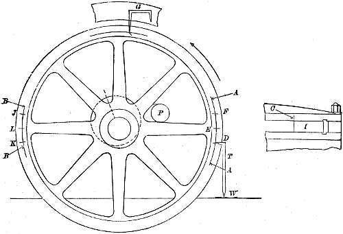
Fig. 2551.
Assuming, then, that all the parts are properly connected and oiled, the valve is set as follows: Upon the face or edge of the fly-wheel an arc, true with the centre of the wheel, should be drawn, as at a b, in Fig. 2551, marking it on opposite sides of its diameter and opposite to the crank pin p. The engine should then be moved in the opposite direction to that in which it is to run, until the guide block i is very near its full travel. A straight-edge must then be placed to bear against, or be coincident with, the end face of block i, and held firmly while a line is drawn across the edge of the guide bars, as shown at c. There should then be fastened to the floor (which must be firm, and not give under the engineer’s weight), a piece of iron w, having a deep centre-punch mark, or its equivalent. A steel tram-rod t, pointed at each end, is then set in the centre-punch mark at w, and with the upper end d a line made across the wheel edge or face. The fly-wheel must then be moved so that the crank passes the dead centre, the guide block moves back and away from the line c, and then approaches it again. When the end of the guide block is again coincident with the line c, the tram should be set as before and a second line, f, marked on the fly-wheel rim, and from these two lines, d and f, the crank may be placed upon its true dead centre as follows:—
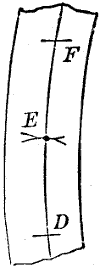
Fig. 2552.
In Fig. 2552 a section of the fly-wheel rim is shown (enlarged for clearness of illustration); from the lines d, f the centre e is found, and marked with a centre punch dot to define it. It will be obvious, then, that if the fly-wheel be moved until this line and dot come fair with the upper edge of the tram t, the guide block will be at the exact end of its travel, and the crank, therefore, on its dead centre. By a similar operation performed with the guide block at the other end of the guide bars, and with lines on the other side of the wheel rim (as shown at b, j, k), the other centre l may be found. In obtaining these centres, however, a question arises as to the direction in which the wheel should be moved for bringing the guide block up to the lines at c, and for marking the lines d f and j k, or for bringing e or l true with the tram point. If the fly-wheel be moved in the opposite direction to that in which the engine is to run, the cross-head journal and crank pin will bear against the boxes of their brasses in the direction in which they will have contact when the engine is running. Suppose, for example, that the top of the fly-wheel when the engine is in motion moves from the cylinder, then the cross-head and crank-pin journals, driven by the piston, will bear against the half-brass nearest to the cylinder, which, when the force-producing motion is applied to the fly-wheel instead of to the piston will be the case when the fly-wheel is moved in the opposite direction. By moving the fly-wheel in an opposite direction to that in which the engine is to run, the lost motion in the journals and bearings is therefore taken up in the proper direction so far as the connecting-rod brasses are concerned, and any lost motion between them and their journals will not impair the set of the valve, as would be the case were the fly-wheel moved in the direction in which it is to run.
But by moving the fly-wheel backwards the play in the eccentric and in all the joints between it and the valve spindle is up in the wrong direction, because the power to move the rods is being applied in the opposite direction to that in which it will be applied when the engine is running, and, therefore, the play motion of the jointed or working parts will cause a lost motion impairing the set of the valve.
Now there are generally more working parts between the eccentric and the valve than between the crank pin and the piston, and hence more liability for lost motion to exist, and it follows that in such case it is better to move the engine in the direction in which it is to run.
It may be remarked, however, that the play may be taken up in the proper direction in both cases, and the engine be brought upon its dead centre, by moving it in the opposite direction to that in which it is to run, and that in setting the eccentrics they be moved on the shaft in the direction in which the engine is to run, as forward for the forward eccentric, and backward for the backward one (assuming the engine to have a link motion, and, therefore, two eccentrics).
It is obvious that any other resting place may be used instead of the floor for the tram; thus in a locomotive the wheel guard may be used, the tram t being used to mark lines on the upper part of the wheel rim, instead of opposite the crank. To set the valve, place the fly-wheel on its dead centre, moving the fly-wheel as directed until one of the points (e or l, say e) comes fair with the point of the tram; then move the eccentric on the shaft until the steam port is open to the required amount of lead, and fasten the eccentric to the main shaft. Next move the fly-wheel around until on the opposite dead centre, and if the lead is the same in amount for both ports the valve is set. Suppose, however, that in this last case the lead is too great; then it shows that the eccentric rod is too long, and it must be shortened to an amount equal to half the difference in the lead. Or suppose that the lead when the wheel was tried on the last dead centre l, was less than for the other port; then the eccentric rod must be lengthened to half the amount of the difference. Assuming that the rod was too long by 1⁄32 of an inch, then it may very often be shortened by simply heating about six inches of its length to a low red heat, and quenching it in water. If the rod has a foot which bolts on a corresponding foot on the eccentric, then to lengthen it a liner of the requisite thickness may be placed between the two feet.
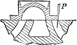
Fig. 2553.
Suppose there is an equal amount of lead at each end but the amount is not sufficient or is too great: then the eccentric must be moved on the shaft until the proper amount of lead appears at the port. The lead must then be again tried at the other dead centre. In moving the eccentric, however, it must, under all conditions, be moved in the direction in which it will rotate, for reasons already given. The best method of measuring the lead where the lines on a rule cannot be seen is with a lead wedge p, as shown in Fig. 2553; this, if slightly forced in, will mark itself, showing how far it entered.
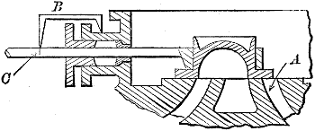
Fig. 2554.
In some practice the position of the valve is transferred to the valve stem outside of the stuffing box or gland, as shown in Fig. 2554, sectional view. The valve stem being disconnected from the rod or arm that drives it, the valve is moved by hand to have the proper lead, as at a; a centre-punch mark is then made outside the stuffing box and a tram b rested thereon; with the other end of the tram a mark c is made on the valve stem. A similar mark is made on the stem when the crank is on the other dead centre, and the tram and marks, applied as shown, are employed instead of measuring the lead at the ports themselves. This involves extra work, but gives no more correct results. It involves marking lines on the valve stem, which is objectionable. If several trials have to be made there is a confusion of lines on the valve stem, and the wrong one is apt to be taken. On the other hand it affords a facility for setting the valve without having the steam chest open, which may in some cases be desirable. If this plan be adopted the lines on the valve rod should not be defined by centre-punch marks, for they will cut the packing in the stuffing box.
When the eccentrics are secured to the shaft by a set-screw only, and not by a feather, it is an excellent plan, after they are finally set, to mark their positions on the shaft, so that if they should move they may be set to these marks without moving the engine around.
For this purpose take a chisel with the cutting end ground to the form of a fiddle drill, one cutting edge being at a right angle to the other. The chisel must be held so that while one edge rests upon the axle, the other edge will bear against the radial face of the eccentric. A sharp blow with a hammer upon the chisel head will make a clean indented cut upon the axle and the eccentric, the two cuts exactly meeting in a point where the eccentric bore meets the axle circumference, so that when they coincide the eccentric is in its proper position.
If the eccentrics of a locomotive should slip when the engine is upon the road, and there are no marks whereby to readjust them, it may be done approximately as follows:—Put the reverse lever in the end notch of the forward gear, then place the crank as nearly on a dead centre as the eye will direct, and open both the cylinder cocks, then disconnect the slide-valve spindle from the rocker arm, and move the valve spindle until the opening of the port corresponding to the dead centre on which the crank stands will be shown by steam blowing through the cylinder cock, the throttle valve being opened a trifle. The position of the valve being thus determined, the eccentric must be moved upon the shaft until the valve spindle will connect with the rocker arm without being moved at all. The throttle valve should be very slightly opened, otherwise so much steam will be admitted into the cylinder that it will pass through any leak in the piston and blow through both cylinder cocks before there is time to ascertain which cock first gives exit to the steam.
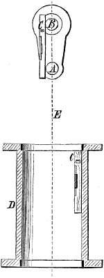
Fig. 2555.
Instead of finding when the crank pin is on the dead centre by means of the process shown in Fig. 2551, it may be found as in Fig. 2555, which is for a vertical engine. On the face of the crank and from the centre of the crank shaft as a centre, draw a circle b equal in diameter to the diameter of the crank pin. Then take a spirit-level c and apply it to the cylinder bore and note where its bubble stands. Then apply the spirit-level to the perimeter of the crank pin a and circle b, and move the crank until the spirit-level bubble stands in the same position as it occupies when applied to the cylinder bore. If the cylinder bore stands truly vertical the bubble will in both cases stand in the middle of the spirit tube; but in any event, the bubble must stand in the same position when applied to the crank as when applied to the cylinder bore, in which case the crank will be on its dead centre whether the cylinder bore be horizontal, vertical, or at an angle, the dotted line e passing through the centre of the crank and the axis of the cylinder bore.
When an engine has two eccentrics, so as to enable the engine to run in either direction, as in the case of a locomotive, it is necessary to consider which eccentric is to be set for the forward, and which for the backward motion. In American locomotive practice it is usual to let the eccentric nearest to the wheel, and, therefore, the most difficult to get at, be for the backward motion, which is the least used, and therefore the least liable to get loose upon the axle.
The eccentric that connects to the top of the link is usually that for the forward motion, and hence that which connects with the eccentric farthest from the wheel.
In testing the lengths of the eccentric rods, work may be saved after the engine is first placed on its dead centre by putting the reverse-lever in the forward notch of the link, and adjusting the forward eccentric until the valve has the proper lead. Then set the reverse-lever in the back notch and move the backing eccentric (in both cases moving them in the direction in which they will run), until the proper amount of lead appears. The engine may then be placed on the other dead centre, and the lead both for forward and backward gear measured, so that if there are any errors both the rods may be corrected for length; but for the final trial the crank pin must be set on its dead centre for each direction of motion separately, so as to take up any lost motion in the connecting-rod brasses.
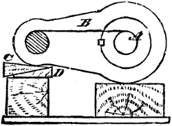
Fig. 2556.
In the case of large marine engines it is not practicable to move or rotate the engines to set the valves, and the eccentrics are therefore adjusted to their positions on the crank shaft by lines before the crank shaft is put into its place or bearings. First, the throw of the crank is set to stand horizontally true by the following method: From the centre of the crank shaft strike a circle of the diameter of the crank pin, as shown in Fig. 2556, at a, and draw upon the face of the crank a line that shall just meet the two circles as denoted by the line b, using a straight-edge, one end of which rests upon the crank pin, while the other end is coincident with the perimeter of the circle a.
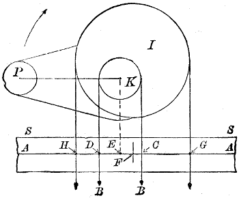
Fig. 2557.
By means of the wedges shown at c d adjust the crank until the line b stands horizontally level, tested by a spirit-level. A straight-edge having straight and parallel edges is set horizontally level, beneath the eccentric, so that its edges will stand parallel with the throw line of the crank. On this straight-edge, and parallel to the edges, is marked the line a a, Fig. 2557. The first process is to mark on a a the centre of the crank shaft k, which is done as follows: Over k is placed the fine line b b, suspending the weights or plumb bobs at b b; coincident with this line and across a a, are marked two lines c d; midway between c d is marked e, which therefore stands directly beneath the shaft centre. From e the line f is drawn distant from e to the amount of lap added to the lead the valve is to have. From f as a centre two lines are drawn across a, their distance apart equalling the full diameter of the eccentric; the plumb line is then placed over the eccentric, and the latter is rotated on the shaft until the plumb lines come exactly fair with the lines g h.
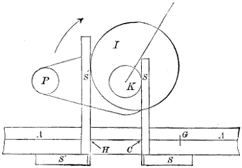
Fig. 2558.
It is obvious that instead of using plumb lines a square may be employed to mark the lines c d, and to set the eccentric to the lines g h, the square being applied as at s and s′, in Fig. 2558.
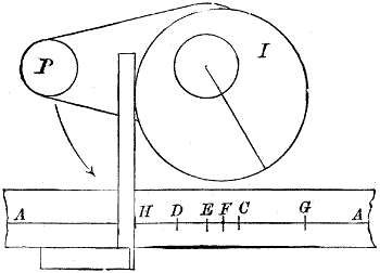
Fig. 2559.
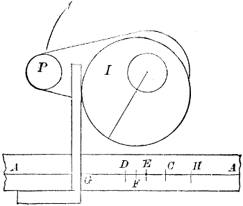
Fig. 2560.
In this example it has been assumed that the direction of crank rotation was to be as denoted by the arrow; but, suppose the crank rotation required to be in the opposite direction, then the marks on the straight-edge would require to be located precisely the same, but the position of the eccentric throw-line would require to be as in Fig. 2559, the perimeter of the eccentric being set to the lines g h as before. The eccentric rod being supposed to connect direct to the valve spindle, without the intervention of a rock shaft, for if there is no rock shaft the eccentric leads in the direction of rotation, while if the engine has a rock shaft the eccentric follows the crank-pin in the direction of rotation, and f must be marked on the crank-pin side of e, as in Fig. 2560.
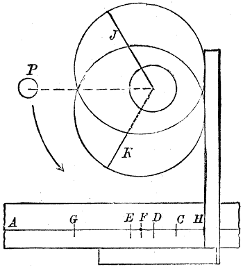
Fig. 2561.
If two eccentrics are used, as in a link motion, the lines for setting one eccentric are equally applicable to both; the lap and lead line f being located on the crank-pin side of e when there is a rock shaft, as is supposed to be the case in Fig. 2561; and on the other side of e when there is no rock shaft; and in this case the eccentric that is to operate the valve to make the engine run forward must have its throw-line following the crank pin, as at j, in Fig. 2561; the eccentric k operating the valve for running backward. Conversely, in the absence of a rock shaft, the throw-line of the forward eccentric leads, while that of the backward eccentric follows the crank pin.
When the line of connection of the eccentric rod is not parallel to the axial line of the cylinder bore, the crank must be placed horizontally level (or if it be a vertical engine, on the dead centre), but instead of the straight-edge being placed parallel to the throw-line of the crank, it must be placed at a right angle to the line of connection of the eccentric rod.
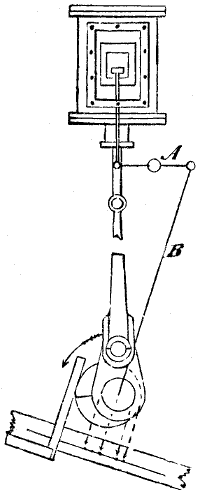
Fig. 2562.
Thus in Fig. 2562 the engine is supposed to be a vertical one, and the crank is, therefore, placed on its dead centre, its throw-line being vertical instead of horizontal as in our previous examples (which were supposed to be for a horizontal engine). It is also supposed to have a rock shaft a; hence the straight-edge is set at a right angle to the line of connection of the eccentric rod which is denoted by b.
It is obvious that to set the crank throw-line vertical the circle b in Fig. 2509 may be used, the spirit-level being resorted to to discover when the crank stands vertical.
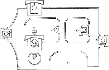
Fig. 2563.
An example in the erection or setting of framed work is shown in Fig. 2563, which represents a side elevation of a frame put together in four parts, two side and two end frames. a and b are journal bearings requiring to stand parallel and true one to the other, b being capable for adjustment in distance from a by means of the adjusting screws g, h. The bearings c, d, e, f, are to be parallel one to the other and to a, b. Their proper relative distances apart, and the axes of all the shafts, are to stand at a right angle to the side frames.
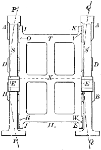
Fig. 2564.
Fig. 2564 represents an end view of the frame, the ends t being bolted to the side frames s and s′ at i, j, k, and l.
Now it is obvious that the ways for the bearings a, b, c, &c., may be trued out, ready to have the brasses fitted before the framework is put together, and that from their positions they would have to be planed out at separate chuckings; supposing, of course, the frame to be too large to be within the capacity of the machine table. It would be difficult to cut all the surfaces of the bearing ways to stand in the same plane, unless there were some true plane to which all might be made common for parallelism.
Furthermore, unless the surfaces where t is fastened to s and s′ are properly bedded to fit each other, bolting them up would spring and bend the frames out of their normal planes. To meet these requirements, there are given to the side frames a slightly projecting surface where the feet of t meet them, and furthermore, the feet of t themselves project beyond the sides of t as shown. These projecting pieces may therefore be planed to a common plane without planing the sides of the respective frames; and this plane should be as nearly as can be parallel with the body of each frame surface. The surfaces of the bearing ways may then be planed parallel to those of the projections, and the jaw surfaces true to the side surfaces, and all the bearing ways will stand true if the frames be properly set—when put together with the bolts. But unless the bedding surfaces at i, j, k, l, be made to bed and fit properly, the whole truth of the bearing ways and their distances apart across the framework may be altered. Thus, supposing the feet of t at i and j to meet s as denoted by the dotted lines o r, and whether the fault lie with the feet of t or with the projections on s the result will be that the pressure of the bolts holding i j to s will bend s so that its plane will be a curve as denoted by the dotted line p p, and the distances apart of the journal ways b b and d d respectively will be wrong, being too wide on account of the bend outward of s.
But the feet may touch on the opposite corners, the surfaces of s′ or of t being out of true or out of full contact, as denoted by the dotted lines v w on k, l; in this case the frame s′ would be bent to the curve q q, and the journal ways would be too close together.
On the other hand, the want of fit between these surfaces may be in the direction of the length of the frame instead of the direction of its height, as has been supposed; or it may be in one direction on one foot and in another direction on another foot. But in whatever direction it does exist, it will inevitably bend and twist the frame.
It must not be taken for granted, that because these surfaces have been planed or milled, that therefore they are true; because frames of this class cannot, if large, be held without springing them to some extent from the pressure of the bolts or other devices necessary to hold them to be cut.
It is not uncommon to plane the surfaces as true as may be, and put the frames together, bolting them up tight, and then applying the straight-edge trammel and rule to test the truth, correcting any error that may be found by inserting pieces of paper, sheet tin or material of requisite thickness on one side of the surfaces, so as to offset the error in their fit and bring the framing true; but this is not the proper way, because it reduces the area of contact, and furthermore renders a new testing and adjustment necessary whenever the frames are taken apart. It is better therefore to apply a straight-edge to the surfaces and true them to it, testing them vertically as by placing the straight-edge across k l, and longitudinally across s′, at k and the corresponding projection at the other end of the frame, filing them until they appear true.
The holes through the frame may be drilled before filing these surfaces, so as to reduce the area to be filed. Since the end frames t do not in this example carry any journals or mechanism, the position of t is not so particular as it otherwise would be; hence, the holes in its feet may be marked off and drilled independently of the frame, the holes being drilled a little too small to allow for reaming with the holes in the frame. The framing will then be ready to put together (all machine work upon them being supposed to be done). The feet of all such frames should be planed true, so that the frame, when put together, may stand true and steady when placed upon a level floor or foundation, and in this case the distance and parallelism of the feet surfaces will be true with the ways or bearings, affording much assistance in holding the frame while putting it together. The height of the holes may be measured and marked from the feet surface, thus insuring truth as far as height is concerned. Lines may be drawn or marked on each side frame, at the proper distance from and parallel with the jaws of the ways a, b, thus completing on the side frames the marking of the location of the centres of the holes for bolting the end frames on.