Volume 1 — Chapter VIII.—SPECIAL FORMS OF THE LATHE.
Reading edition
The lathe is made in many special or limited forms, to suit particular purposes, the object being to increase its efficiency for those purposes, which necessarily diminishes its capacity for general work.
In addition to this, however, there are machine tools whose construction varies considerably from the ordinary form of lathe, which nevertheless belong to the same family, and must, therefore, be classified with it, because they operate upon what is essentially lathe work. Thus boring and turning mills are essentially what may be termed horizontal lathes.
VOL. I. WATCHMAKER’S LATHE. PLATE VIII.
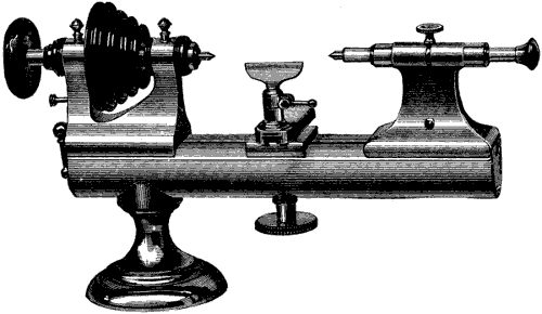
Fig. 650.
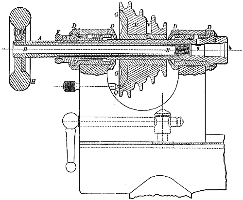
Fig. 651.
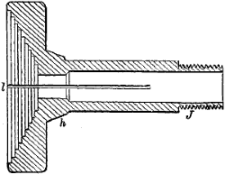
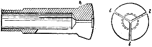
Fig. 653.
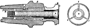
Fig. 652. Fig. 654.
Figs. 650 to 655 inclusive, represent the American Watch Tool Company’s special lathes for watch-makers, which occupy a prominent position in Europe, as well as in the United States.
In lathes of this class, refinement of fit, alignment, truth, and durability of parts are of the first importance, because of the smallness of the work they perform, and the accuracy to which that work must be made. Furthermore, such lathes must be constructed to hold and release the work as rapidly as possible, because in such small work the time occupied by the tools in cutting is less, while that occupied in the insertion and removal of it is greater in comparison than in larger jobs; it often takes longer to insert and remove the work than to perform it.
These facts apply with equal force to all such parts as require the removal to or from the lathe-bed, or frequent adjustment upon the same. Thus the devices for holding and releasing the tool post or hand rest and tailblock are each so constructed that they may be set without the use of detached wrenches.
Fig. 650 represents a general view of the lathe, while Fig. 651 represents a sectional view of the headstock. The live spindle consists of two parts, an outer sleeve a a, having journal bearing in the head, and an inner hollow spindle b b, threaded at its front end e, to receive the chucks. The main spindle at the front end works in a journal box c, that is cylindrical to fit the headstock, but double coned within to afford journal bearing to the spindle a. The inner step of this double cone is relied upon mainly to adjust the diametral fit of the bearing, while the outer step is relied upon mainly to adjust the end fit of the spindle; but it is obvious in both cases there is an action securing simultaneously the diametral and the end fit. In the back bearing there are two cones. The outer one r is cylindrical outside where it fits into the head, and coned in its bore to receive the second cone s, which rotates with spindle a. The nut f is threaded upon a, so that by operating f, a is drawn within c, and s is simultaneously moved within r, so that both bearings are simultaneously adjusted. d d are dust rings, being ring-caps which cover the ends of the bearings and the oil holes so as to prevent the ingress of dust.
The inner spindle b has a bearing in a at the back end to steady it, and a bearing at end e, and is provided with the hand wheel h, by which it may be rotated to attach the chucks which screw into its mouth at e. To rotate or drive the chucks there is in a a feather at g, the chucks having a groove to receive this feather and screwing into b at e, when b is rotated.
The mouth of a is coned, as shown at h, and the chucks are provided with a corresponding male cone, as shown at h in Figs. 652 and 653, so that the chucks are supported and guided by the cone, and are therefore as close to the work as possible while having a bearing at g. But the cone on the chucks being split, (as is shown in Fig. 652), rotating b while holding a stationary (which may be done by means of the band pulley p), causes the chucks to move endwise in a, and if the motion is in the direction to draw the chuck within a, the cone h causes the chuck to close upon and grip the work. Thus in Fig. 652 is shown a step chuck. The thread at j enters the end e of b, in Fig. 651, which screws upon it. Cone h fits mouth h in Fig. 651, and l represents the splits in the chuck, which enable it to close when the cone h is drawn within the mouth h of spindle a.
The chuck is employed to hold cylindrical plates or discs, such as wheels and barrels, and the various steps are to suit the varying diameters of these parts in different sizes of watches.
Fig. 653 represents a wire chuck, having the cone at h, and the three splits at l, as before, the cone-mouth h closing the chuck as the latter is drawn within the spindle a.
In both the chucks thus far described, the construction has been arranged to close the splits and thus grip the circumferences of cylindrical bodies, but in Fig. 654 is shown the arrangement for enabling the chuck to expand and grip the bores of hollow work, such as rings, &c.
The outer spindle a corresponds to the outer spindle a in Fig. 651, and the inner one to spindle b in that figure. The chuck is here made in two separate parts, a sleeve v fitting in and driven by a, and a plug x fitting into a cone in the mouth of v, and screwing into the end of drawing spindle b. But while v is driven by and prevented from rotating within a by means of the feather at g, so likewise x is prevented from rotating within v by means of a feather h fast in x and fitting into a groove or featherway in v. It follows then that when b is rotated x may be traversed endways in v, to open or close the steps y according to the direction of rotation of b.
It will now be apparent that in the case of chucks requiring to grip external diameters, the gripping jaws of the chucks will, when out of the lathe, be at their largest diameter, the splits l being open to their fullest, and that when by the action of the cones, they are closed to grip the work, such closure must be effected against a slight spring or resistance of the jaws, and this it is that enables and causes the chuck to open out of itself, when the enveloping cone permits it to do so.
But in the case of the opening or expanding chuck, the reverse is the case, and the chuck is at its smallest diameter (the splits l being at their closest) when the chuck is removed from the lathe, as is obviously necessary. In reality the action is the same in both cases, for the chuck moves to grip the work under a slight resistance, and this it is that enables it to readily release the work when moved in the necessary endwise direction.
The band pulley p is fast upon a, and is provided with an index of 60 holes on its face g, and which are adjusted for any especial work by a pin q, so that a piece of work may have marked on it either 60, 30, 20, 15, 12, 10, 6, 5, 4, 3, or 2 equidistant lines of division, each of those numbers being divisors of 60. In marking such lines of division upon the work a sharp point may be used, supported by the face of the hand rest as a guide; or a sharp-pointed tool may be placed in the slide rest to cut a deeper line upon the work. The index plates used for cutting wheels and pinions may be placed on the rear end of a, the pawl being secured to the work-bench. The wheel h is for rotating spindle b to screw the chucks on or off the same.
VOL. I. DETAILS OF WATCHMAKER’S LATHE. PLATE IX.
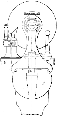
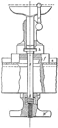
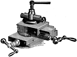
Fig. 657.
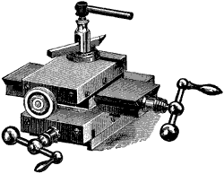
Fig. 655. Fig. 656. Fig. 658.
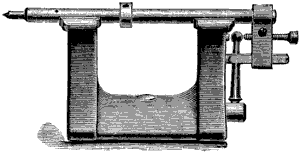
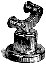
Fig. 659. Fig. 660.
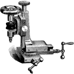
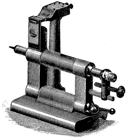
Fig. 661. Fig. 662.
Fig. 655 represents an end view from the tailstock end of the lathe; a′ is the bed having the angles a a to align the heads and rests. The means of holding or releasing the tailstock, on the lathe-bed, is the same as that for holding the headstock, the construction being as follows: b is the shoulder of a bolt through which passes the shaft c, with a lever d to operate it. This shaft is eccentric where it passes through the bolt, so that by using the lever aforesaid the bolt secures or releases the head according to the direction in which it is moved. A very small amount of motion is needed for this. The standard for the hand rest is split, and a screw is used to tighten it in an obvious manner, the screw being operated by the handle e′. An end view of the rest, showing the device for securing the foot h to the bed, is shown in Fig. 656, f is a shoe spanning the bed and fitting to the bed angles a. Through f passes the bolt g, its head passing into the T-shaped groove h; n′ is a hand wheel for operating bolt g. At s is a spiral spring, which by exerting an end pressure on washer w and nut n′, pulls g and the head h down upon f, and therefore f down upon the bed, whether the rest be locked to the bed or not; hence when n′ is released to remove or adjust the rest, neither dust nor fine cuttings can pass either between the rest and shoe or the shoe and the lathe-bed, and the abrasion that would otherwise occur is thus avoided.
Two qualities of these lathes are made: in the better quality all the working parts are hardened and afterwards ground true. In the other the parts are also ground true, but the parts (which in either case are of steel) are left soft for the sake of reducing the cost. In all, the parts are made to gauge and template, so that a new head, tailstock, or any other part in whole or in detail may be obtained from the factory, either to make additions to the lathe or to replace worn parts.
Two styles of slide rest are made with these lathes: in the first, shown in Fig. 657, the swivel for setting the top slide at an angle for taper turning is at the base of the top slide, hence the lower slide turns all radial faces at a right angle to the line of lathe centres. In the second, Fig. 658, there is a third slide added at the top, so that the bottom slide turns radial faces to a right angle with the line of lathe centres, the next slide turns the taper and the top slide may be used to turn a radial face at a right angle to the surface of the taper, and not at a right angle to the axis of the work. Both these rests are provided with tool post clamps, to hold tools made of round wire, such clamps being shown in position in figure 657.
Fig. 659 represents an additional tailstock for this lathe, the tail spindle lying in open bearings so that it can be laid in, which enables the rapid employment of several spindles holding tools for performing different duties, as drilling, counter-boring, chamfering, &c.
Fig. 660 represents a filing fixture to be attached to the bed in the same manner as the slide rest. It consists of a base supporting a link, carrying two hardened steel rolls, upon which the file may rest, the rolls rotating by friction during the file strokes, and serving to keep the file flat and fair upon the work.
Fig. 661 represents a fixture for wheel and pinion cutting; it is attached to the slide rest. When the cutter spindle is vertical the belt runs directly to it from the overhead counter shaft, but when it is horizontal the belt passes over idler pulleys, held above the lathe. The cutter spindle is carried on a frame, pivoted to the sliding piece on the vertical slide, so that it may be swivelled to set in either the vertical or horizontal position.
Fig. 662 represents a jewelers’ rest for this lathe. It fits on the bed in the place of the tailstock, and is used for cutting out the seats for jewels, in plates, or settings. It is especially constructed so as to receive the jewel at the top and bore the seating to the proper diameter, without requiring any measurements or fitting by trial, and the manner in which this is accomplished is as follows:—
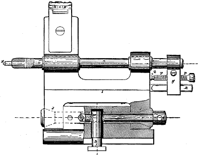
Fig. 663.
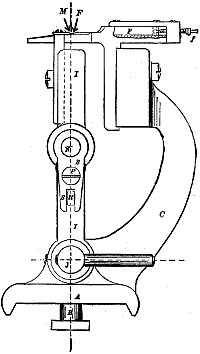
Fig. 664.
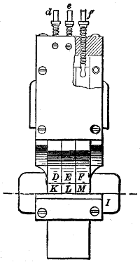
Fig. 665.
Fig. 663 is a side elevation, Fig. 664 an end elevation, and Fig. 665 a plan view of this rest, and similar letters of reference indicate like parts in each of the three figures. a is the base, held to the lathe bed by the bolt b, whose operation is the same as that already described for the head and tailstocks.
In one piece with a is the arm c, carrying at its head three gauge tongues or pieces d e f, which are adjustable by means of the screws d e f, which move the gauge tongues horizontally. Through a suitable guide i is a standard or head; pivoted to a at j j, and carrying at its top three gauge tongues k l m.
Midway between pivots j j and the ends of the gauge tongues, is the centre or tool carrying spindle o. If a piece of work, as a jewel, be placed between the tongues f and m, Fig. 664 [swinging m, and with it i (which is pivoted at j), laterally], then the point of the centre n will be thrown out of line with the lathe live spindle half the diameter of the jewel, because from j to the centre n, of o, is exactly one half of the vertical distance from j to the jewel. If then a tool be placed in the dead centre and its cutting edge is in line with the axis of spindle o, it will bore a hole that will just fit the jewel. Hence placing the jewel between the two tongues sets the diameter to which the tool will bore and determines that it shall equal the diameter of the jewel.
The object of having three pair of gauge tongues is to enable the obtaining of three degrees of fit; thus with a piece placed between d k the hole may be bored to fit the piece easily, with it placed between e l the fit may be made barely movable, while with it placed between f m the fit may be too tight to be a movable one save by pressure or driving, each degree of fit being adjusted by means of the screws e f g.
The tool is fed by moving spindle o by hand, the screw p being adjusted so that its end abuts against stop q, when the hole is bored to the requisite depth; r is simply a guide for the piece s, which being attached to o, prevents it from rotating.
In watch manufactories special chucks and appliances are necessary to meet their particular requirements. There is found to exist, for example, in different rods of wire of the same nominal diameter, a slight variation in the actual diameter, and it is obvious that with the smaller diameters of wire the split chucks will pass farther within the mouth h of a, Fig. 651, because the splits of the chucks will close to a greater extent, and the cones on the chucks therefore become reduced in diameter.
If then it be required to turn a number of pieces of work to an exact end measurement, or a number of flanges or wheels to equal thicknesses, without adjusting the depth of cut for each it becomes necessary to insure that the successive pieces of work shall enter the chucks to an equal distance, notwithstanding any slight variation in the work diameter at the place or part where it is gripped by the chuck.
To accomplish this end what is termed a sliding-spindle head is employed. In this the outer spindle has the end motion necessary to open and close the chuck, the chuck having no end motion.
Large image (141 kB).
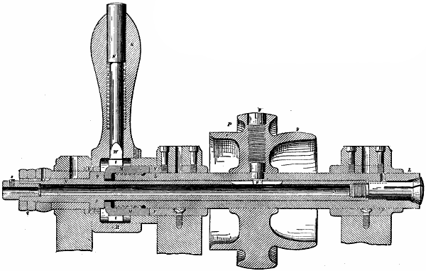
Fig. 666.
The construction of this sliding-spindle head is shown in Fig. 666, in which a wire chuck is shown in position in the spindles; l is the live spindle passing through parallel bearings, so that it may have end motion when the nut m is operated. The inner spindle n to which the chucks are screwed is prevented from having end motion by means of the collar p and nut q at the rear bearing. When nut m is rotated and n is held stationary by means of the pulley p, l slides endways, and the chuck opens or closes according to the direction in which the nut moves the spindle l.
To regulate the exact distance to which the work shall be placed within the chuck, a piece of wire rod may be placed within the hollow spindle n being detained in its adjusted position by the set screw s.
The construction whereby the nut is permitted to revolve with spindle l, and be operated by hand to move spindle l when the lathe is at rest, is as follows.
The cylindrical rim t of the nut is provided with a series of notches arranged around its circumference. r is a lever whose hub envelops nut m, but has journal bearing on v. r receives the pin s, which rests upon a spiral spring t. When, therefore, s is pushed down it depresses the spring t and its end w enters some one of the notches in the rim t, and operates the nut after the manner of a ratchet. But so soon as the end pressure on r is released, the spiral spring lifts it and m is free to revolve with l as before. The inner spindle is driven by means of the feather g.
Pulley p has two steps y for the belt, and a friction step z, around which passes a friction band operated by the operator’s foot to stop the lathe quickly. This performs two functions, as follows. The thread of m is a left-hand one so that the inertia of the nut will not, when the lathe is started, operate to screw the nut back, and release the chuck jaws from the work, by moving spindle l endwise. Per contra, however, in stopping the lathe suddenly by means of the brake, there is a tendency of nut m to stop less quickly than spindle l, and this operates to unscrew nut n and release the work. To assist this r is sometimes in lathes for watch manufactories provided with a hand wheel whose weight is made sufficient for the purpose.
Large image (78 kB).
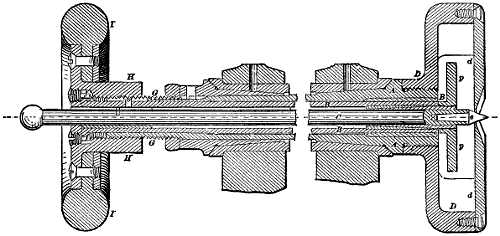
Fig. 667.
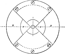
Fig. 668.
Figs. 667 and 668 represent a pump centre head for watch manufactories, being a device for so chucking a piece of work that a hole may be chucked true and enlarged or otherwise operated upon, with the assurance that the work will be chucked true with the hole. Suppose two discs be secured together at their edges, their centres being a certain distance apart, as, for example, a top and bottom plate of a watch movement, and that the holes of one plate require to be transferred to the other, then by means of this head they may be transferred with the assurance that they shall be axially in line one with the other, and at a right angle to the faces of the plates, as is necessary in setting jewels in a watch movement.
In holes of such small diameters as are used in watch work, it is manifestly very difficult to set them true by the ordinary methods of chucking and it is tedious to test if they are true, and it is to obviate these difficulties that the pump centre head is designed. Its operation is as follows.
There are in this case three spindles a, b, and c, in Fig. 667; a corresponds to spindle a in Fig. 651, driving the chuck d which screws on a as shown; b simply holds the work against the face d of d, and c holds the work true by means of the centre e, which enters the hole or centre in the work and is withdrawn when the work is secured by spindle b.
The chuck d is open on two sides as shown at e e in Fig. 668, which is an end face view of the chuck, and through these openings the work is admitted to the chuck. The rod or spindle c is then pushed, by hand, endwise, its centre e entering the hole or centre in the work (so as to hold the same axially true) and forcing the work against the inside faces d, spindle b is then operated, the face p forcing the work against face d, and between these two faces d p the work is held and driven by friction. The spindle c and its centre e is then withdrawn by hand, leaving the hole in the work free to be operated upon.
The journal bearings for spindle a are constructed as described for a in Fig. 666; spindle b is operated endways within a as follows. a is threaded at g to receive the hub h of wheel i, at the end of b is a collar which is held to and prevented from end motion within the hub h: hence when wheel i is rotated and a is held stationary (by means of the band pulley), h traverses on g and carries b with it. Operating i in one direction, therefore moves p against the work, while operating it in the other direction releases face p from contact with the work.
It is obviously of the first importance that the spindle c be held and maintained axially true, notwithstanding any wear, and that it be a close fit within b so as to remain in any position when the lathe is running, and thus obviate requiring to remove it. To maintain this closeness of fit the following construction is designed. Between spindle a and spindle b, at the chuck end of the two, is a steel bush which can be replaced by a new one when any appreciable wear has taken place. Between b and c are two inverted conical steel bushes, which can also be replaced by new ones, to take up any wear that may have taken place.
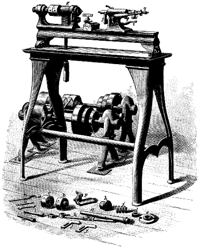
Fig. 669.
Fig. 669 represents an improved hand lathe by the Brown and Sharpe Manufacturing Company, of Providence, R. I. It is specially designed for the rapid production of such cylindrical work as may be held in a chuck, or cut from a rod of metal passing through the live spindle, which is hollow, so that the rod may pass through it. Short pieces may be driven by the chuck or between the centres of a face plate (shown on the floor at e) screwing on in the ordinary manner. When, however, this face plate is removed a nut d screws on in its stead, to protect the thread on the live spindle.
The chuck for driving work in the absence of face plate e (as when the rod from which the work is to be made is passed through the live spindle) may be actuated to grip or release the work without stopping the lathe. The pieces j j are to support the hand tool shown in Figs. 1313 and 1314, in connection with hand turning, the tool stock or handle being shown at k on the floor. The lever for securing the tailstock to or releasing it from the shears is shown at t. The tail spindle is operated by a lever pivoted at g so that it may be operated quickly and easily, while the force with which the tail spindle is fed may be more sensitively felt than would be the case with the ordinary wheel and screw, this being a great advantage in small work. The tail spindle is also provided with a collar r, that may be set at any desired location on the spindle to act as a stop, determining how far the tail spindle can be fed forward, thus enabling it to drill holes, &c., of a uniform depth, in successive pieces of work.
The live spindle is of steel and will receive rods up to 1⁄2 inch in diameter. Its journals are hardened and ground cylindrically true after the hardening. It runs in bearings which are split and are coned externally, fitting into correspondingly coned holes in the headstock. These bearings are provided with a nut by means of which they may be drawn through the headstock to take up such wear in the journal and bearing fit, as may from time to time occur.
It is obvious that the lathe may be removed from the lower legs and frame and bolted to a bench, forming in that case a bench lathe.
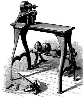
Fig. 670.
Fig. 670 represents a special lathe or screw slotting machine, as it is termed, for cutting the slots in the heads of machine or other screws. The live spindle drives a cutter or saw e, beneath which is the device for holding the screws to be slotted, this device also being shown detached and upon the floor.
The screw-holding end of the lever a acts similarly to a pair of pliers, one jaw of which is provided on handle a, while the other is upon the piece to which a is pivoted. The screw to be slotted is placed between the jaws of a beneath e; handle a is then moved to the left, gripping the screw stem; by depressing a, the screw head is brought up to the cutter e and the slot is cut to a depth depending upon the amount to which a is depressed, which is regulated by a screw at b; hence after b is properly adjusted, all screw heads will be slotted to the same depth.
The frame carrying the piece to which a is pivoted may be raised or lowered to suit screws having different thicknesses of head by means of a screw, whose hand nut is shown at d.
The frame for the head of the machine is hollow, and is divided into compartments as shown, in which are placed the bushings used in connection with the screw-gripping device, to capacitate it for different diameters of screws, and also for the wrenches, cutters, &c.
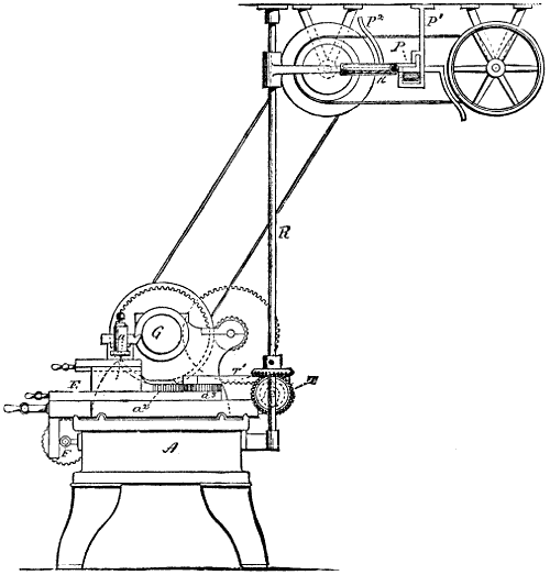
Fig. 671.
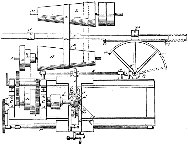
Fig. 672.
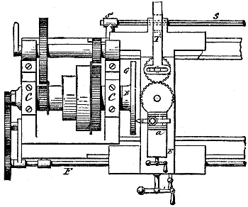
Fig. 673.
Figs. 671, 672, and 673, represent a lathe having a special feed motion designed and patented by Mr. Horace Lord, of Hartford, Connecticut. Its object is to give to a cutting tool a uniform rate of cutting speed (when used upon either flat or spherical surfaces), by causing the rotations of the work to be retarded as the cutting tool traverses from the centre to the perimeter of the work, or to increase as the tool traverses from a larger to a smaller diameter. If work of small diameter be turned at too slow a rate of cutting speed, it is difficult to obtain a true and smooth surface; hence, as the tool approaches the centre, it is necessary to increase the speed of rotation. As lathes are at present constructed, it is necessary to pass the belt from one step to another of the driving cone, to increase the speed. In this two disadvantages are met with. First, that the increase of speed occurs suddenly and does not meet the requirements with uniformity. Second, that the strain upon the cutting tool varies with the alteration of cutting speed. As a result, the spring of the parts of the lathe, as well as of the cutting tool, varies, so that the cut shows plainly where the sudden increase or decrease (as the case may be) of cutting speed has occurred. The greatest attainable degree of trueness is secured when the cutting speed and the strain due to the cut are maintained constant, notwithstanding variations of the diameter.
This, Mr. Lord accomplishes by the following mechanism: Instead of driving the lathe from an ordinary countershaft, he introduces a pair of cones which will vary the speed of the lathe as shown in Fig. 672 as applied to ball turning. l is a belt cone upon the counter-shaft driven from the line shaft. l drives h, which may be termed the lathe countershaft, and from the stepped cone k the belt is connected to the lathe in the usual manner. p is a shipper bar to move the belt n upon and along the belt cones, and thus vary the speed. r is a vertical shaft extending up at the end of the lathe and carrying a segment. This segment is connected to the belt shipper bar p by two cords, one passing from r1 around half the segment to r2, and the other passing from r3 to r4, so that if the segment be rotated, say to the right, it and the bar will move as denoted by the dotted lines, or if moved in an opposite direction, the bar motion will correspond and move the belt n along the cones respectively left or right.
At the back of the lathe is a horizontal shaft s, similar to an ordinary feed spindle, and connected to the segment shaft by a pair of bevel gears s2. Between the two ears e e, at the rear of the lathe carriage, is a pinion t, which drives the splined shaft s, which works in a rack t′. The tool rest is pivoted directly beneath the ball, to be turned after the usual manner of spherical slide rests, and carries a gear a2, which, as the rest turns, rotates a gear a3. Upon the face of the latter is a pin a4 working in a slot a5 at the end of the rack t′; hence as the tool rest feeds, motion is transmitted from a2 through a3, a4, a, t′, t, and s s2 to r, which operates the belt shipper p. As it is the rate of tool feed that governs the speed of these motions, the effect is not influenced by irregularity in feeding; hence the speed of the work will be equalized with the tool feed under all conditions. The direction of motion of all the parts will correspond to that of the tool feed from which their motion is directed, and therefore the work speed will augment or diminish automatically to meet the requirements.
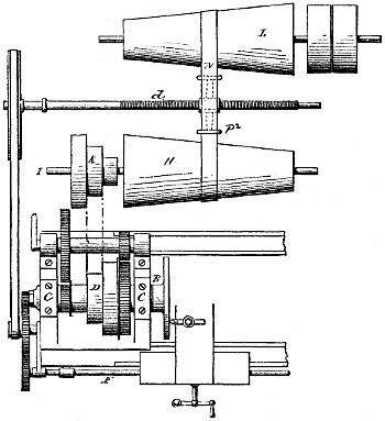
Fig. 674.
Fig. 673 illustrates the action of the mechanism when used for surfaces, like a lathe face plate. In this case the two gears and the rack t′ simply traverse with the cross-feed slider, and the mechanism is actuated as before. In Fig. 674 a different method of actuating the belt shipper is illustrated. A pulley is attached to the intermediate stud of the change gears, being connected by belt to the shipper, which is threaded as shown at d, the belt guiding forks, as p2, being carried on a nut actuated by the screw d.
Cutting-off Machine.—The cutting-off machine is employed to cut up into the requisite lengths pieces of iron from the bar. As the cutting is done by a tool, the end of the work is left true and square and a great saving of time is effected over the process of heating and cutting off the pieces in the blacksmith’s forge, in which case the pieces must be cut off too long and the ends left rough.
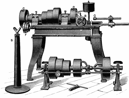
Fig. 675.
Fig. 675 represents Hyde’s cutting-off machine, which consists of a hollow live spindle through which the bar of iron is passed and gripped by the chucks c c. At g is a gauge rod whose distance from the tool rest r determines the length of the work. f is a feed cone driven by a corresponding cone on the live spindle and driving the worm w, which actuates the self-acting tool feed, which is provided with an automatic motion, which throws the feed out of action when the work is cut off from the bar. The stand s is movable and is employed to support the ends of long or heavy bars.
To finish work smooth and more true than can be done with steel cutting tools in a lathe, what are known as grinding lathes are employed. These lathes are not intended to remove a mass of metal, but simply to reduce the surfaces to cylindrical truth, to true outline and to standard diameter, hence the work is usually first turned up in the common lathe to the required form and very nearly to the required diameter, and then passed to the grinding lathe to be finished. The grinding lathe affords the best means we have of producing true and smooth cylindrical parallel work, and in the case of hardened work the only means. In place of steel cutting tools an emery wheel, revolved at high speed from an independent drum or wide pulley, is employed, the direction of rotation of the emery wheel being opposite to that of the work.
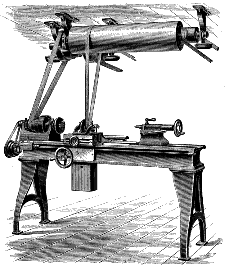
Fig. 676.
Fig. 676 represents Pratt and Whitney’s weighted grinding lathe. The headstock and tailstock are attached to the bed in the usual manner, the frame carrying the emery wheel is bolted to the slide rest as shown, the rest traversing by a feed spindle motion. The carriage traverse is self-acting and has three changes of feed, by means of the feed cones shown.
To enable the lathe to grind taper work (whether internal or external) the lathe is fitted with the Slate taper attachment shown in Figs. 508 and 509.
It is obvious that in a lathe of this kind, there must be an extra overhead shaft, driving a drum of a length equal to the full traverse of the lathe carriage, or of the plate carrying the head and tailstocks, and the arrangement of this drum with its belt connection to the pulley on the emery wheel arbor, is sufficiently shown in figure. To protect the ways of the bed from the abrasion that would be caused by the emery and water falling upon them, guards are attached to the carriage extending for some distance over the raised Vs.
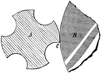
Fig. 677.
It is essential that the work revolve in a direction opposite to that of the emery wheel, for the following reasons. In Fig. 677 let a represent a reamer and b a segment of an emery wheel. Now suppose a and b to revolve in the direction that would exist if one drove the other from frictional contact of the circumferential surfaces, then the pressure of the cut would cause the reamer a to spring vertically and a wedging action between the reamer and wheel would take place, the reamer vibrating back and forth under varying degrees of this wedging; as a result the surface of a would show waves and would be neither round nor smooth.
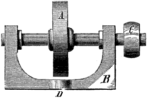
Fig. 678.
In the absence of a proper grinding lathe, an ordinary lathe is sometimes improvised for grinding purposes, by attaching to the slide rest a simple frame and emery wheel arbor with pulley attached as in Fig. 678, in which a is the emery wheel, c the pulley for driving the arbor, and b the frame, d being a lug for a bolt hole to hold the frame to the lathe rest.
In some cases the work may remain stationary and the emery wheel only rotate. Thus, suppose it was required to grind the necessary clearance to relieve the cutting edge c of the reamer, then a could be rotated until c stood in the required position with relation to b, and the revolving emery wheel may either be traversed along, or the work may traverse past the wheel, according to the design of the grinding lathe, but in either case a remains stationary during each cut traverse; after each successive traverse a may be rotated sufficiently to give a cut for the next traverse.
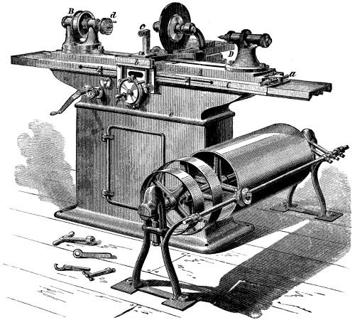
Fig. 679.
Fig. 679 represents Brown and Sharpe’s universal grinding lathe.
This lathe is constructed to accomplish the following ends. First, to have the lathe centres axially true with the work when grinding tapers, so that the lathe centres shall not wear and gradually throw the work out of true from the causes explained in the remarks on turning tapers in a lathe of ordinary construction.
Second, to have the headstock b capable of lateral swing, so as to enable the grinding of taper holes.
The manner in which these results are accomplished is as follows:
The headstock b and the tailstock are attached to the bed or table a, which is pivoted at its centre to a table beneath it, this latter table being denoted by c. This permits table a to swing laterally upon c and stand at any required angle. To enable a delicate adjustment of this angle, a screw a having journal bearing in a lug on c is threaded through a piece carried in projection on the end of a.
The table c traverses back and forth past the emery wheel, after the manner of an ordinary iron planing machine, the mechanical parts effecting this motion being placed within the bed upon which c slides. The carriage supporting the emery frame and table d remains stationary in its adjusted position, while c (carrying a with it) traverses back and forth.
Now, if a be adjusted so that the line of centres is parallel with the line of motion of c, then the work will be ground parallel, but if a be operated to move a upon its pivoted centre and draw the tailstock end of a towards the operator, then the work will be ground of larger diameter at the tailblock end. Conversely, by operating screw a in the opposite direction, it will be of smaller diameter at that end.
But whatever the degree of angle of a to c, the line of centres of the head and tailstocks will be axially true with the axial line of the work, hence the work centres are not liable to wear off true, as is the case when the tailstock only sets over (as will be fully explained in the remarks on taper turning).
To grind conical holes the headstock b is pivoted at its centre upon a piece held by bolts to the table a, so that it is capable of being swung laterally to the degree requisite for the required amount of taper in the work bore, and of being locked in that adjusted position, the work being held in a chuck screwed upon the spindle in the usual manner. The pulley d being removed to enable the grinding of cones, chamfers, or tapers of too great an angle to permit of a setting over to the required degree. The line of cross-feed motion of the emery wheel may be set to the required angle as follows.
The frame carrying the emery wheel arbor is fixed to a table d, which is capable of being operated (in a direction across the table a) upon a carriage beneath a. This carriage, or saddle (as it may perhaps be more properly termed), is pivoted so as to allow of its movement and adjustment in a horizontal plane, and since d operates in the slide of the carriage, its line of motion in approaching or receding from the line of centres will be that to which the saddle is set. This enables the grinding of such short cones as the circumferences of bevelled cutters, chamfers, &c., at whatever angle the saddle may be set, however, d may be operated from the feed screw disc and handle f.
The lever handle at the left hand is for operating or rather traversing c by hand; b is a pan to catch the grit and water, the water being led to the back of machine into a pail; c is a back rest to steady the work when it is slight and liable to deflection.
The slot and stops shown upon the edge of c are to regulate the points of termination of the traverse (in the respective directions) of c. A guard is placed over the emery wheel to arrest and collect the water cuttings, &c., which would otherwise fly about.
A large amount of work which has usually been filed in a lathe, can be much more expeditiously and accurately finished by grinding in this machine.
Work to be ground may obviously be held in the same chucks or work-holding appliances as would be required to hold it to turn it with cutting tools, or where a quantity of similar work is to be done special chucks may be made.
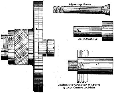
Fig. 680.
Fig. 680 (from The American Machinist) shows a special chuck for grinding the faces of thin discs, such as very thin milling cutters, which could not be held true by their bores alone. The object of the device is to hold the cutter by its bore and then draw it back against the face of the chuck, which, therefore, sets it true on the faces. The construction of the chuck is as follows. The hub screws upon the lathe like an ordinary face plate, and has a slot running diametrically through it. Upon its circumference is a knurled or milled nut c, which is threaded internally to receive the threaded wings of the bush b. A collar behind c holds it in place upon the hub. To admit piece b the front of the chuck is bored out, and after b is inserted and its threaded wings are engaged in the ring nut c a collar is fitted over it and into the counter-bore to prevent b from having end motion unless c is revolved. d is a split bushing that fits into b, its stem fitting the bore of the disc, or cutter to be ground: the enlarged end of d is countersunk to receive the head of the screw e, whose stem passes through d and threads at its end into b, so that when e is screwed up its head expands d and causes it to grip the bore of the disc or cutter to be ground. After e is screwed up the ring nut c is revolved, drawing b within the chuck and therefore bringing the inside face of the disc or cutter against the face of the chuck or face plate, and truing it upon the bushing d. All that is necessary therefore in using the chuck is to employ a bushing of the necessary diameter for the bore of the cutter, insert it in b, then screw up the screw e and then revolve the ring nut c until the work is brought to bear evenly and fair against the face of the chuck, and to insure this it is best not to screw e very tightly up until after the ring nut c has been operated and brought the work up fair against the chuck face.
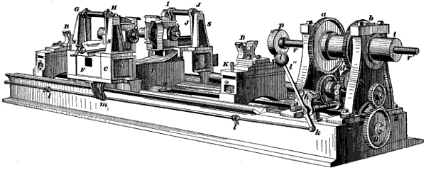
Fig. 681.
Fig. 681 represents the J. Morton Poole calender roll grinding lathe, which has attained pre-eminence both in Europe and the United States from the great accuracy and fine finish of the work it produces.
In all other machine tools, surfaces are made true either by guiding the tool to the work or the work to the tool, and, in either case, guide-ways and slides are employed to determine the line of motion of the tool or the work, as the case may be. These guideways and slides are usually carried by a framing really independent of the work, so that the cutting depends entirely upon the truth or straightness of the guideways, and is not determined by the truth, straightness, or parallelism of the work itself. As a result, the surface produced depends for its truth upon the truth of the tool-guiding ways. In the Poole lathe, however, while guideways are necessarily employed to guide the emery wheels in as straight a line as is possible, by means of such guides, the roll itself is employed as a corrective agent to eliminate whatever errors may exist in the guide. The rolls come to this machine turned (in the lathe Fig. 730), and with their journals ground true (on dead centres).
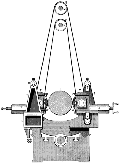
Fig. 682.
Fig. 681 represents a perspective view of the machine, as a whole. It consists of a driving head, answering to the headstock of an ordinary lathe. b b are bearings in which the rolls are revolved to be ground. c is a carriage answering to the carriage of an ordinary lathe, but seated in sunken V-guideways, corresponding to those on an ordinary iron planing machine. Referring to Fig. 682, f is a swing-frame suspended by four links at g, h, i, j, which are upon shafts having at their ends knife edges resting in small V-grooves on the surface of standards s, which are fixed to carriage c. The frame f being thus suspended and being in no way fixed to c, it may be swung back and forth crosswise of the latter, the links at g, h, i, j, swinging as pendulums. At the top of f are two slide rests a a, one on each end, carrying emery or corundum wheels w, and the roll r, which rests in the bearings b, rotates between these emery wheels. The carriage c is fed along the bed as an ordinary lathe carriage, and the emery wheels are revolved from an overhead countershaft. Now, it will be found that from this form of construction the surface of the roll, when ground true, serves as a guide to determine the line of motion of the emery wheels, and that the emery wheels may be compared to a pair of grinding calipers that will operate on such part of the roll length as may be of larger diameter than the distance apart of the perimeters of the emery wheels, and escape such parts in the roll length as may be of less diameter than the width apart of those perimeters; hence parallelism in the roll is inevitable, because it is governed solely by the width apart of the wheel perimeters, which remain the same, while the wheels traverse the roll, except in so far as it may be affected by wear of emery-wheel diameters in one traverse along the roll.
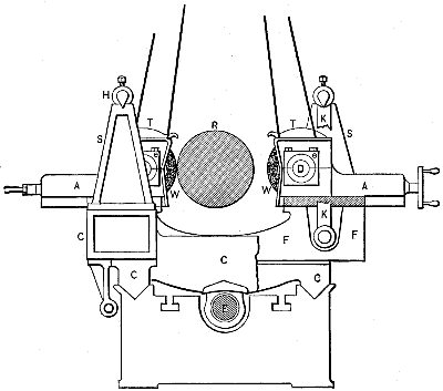
Fig. 683.
Supposing now that we have a roll r (Fig. 683), placed in position and slowly revolved, and that the carriage c is fed along by feed screw e, then the line of motion of the emery wheels will be parallel to the axis of the roll, provided, of course, that the bearings b (Figs. 681 and 687) are set parallel to the V-guideways in the bed, and that these guideways are straight and parallel. But the line of travel of the emery wheels is not guided by the Vs except in so far as concerns their height from those Vs, because the swing-frame is quite free to swing either to the right or to the left, as the case may be. Its natural tendency is, from its weight, to swing into its lowest position, and this it will obviously do unless some pressure is put on it in a direction tending to swing it. Suppose, then, that instead of the roll running true, it runs eccentrically, or out of true, as it is termed, as shown in Fig. 683, when the high side meets the left-hand wheel it will push against it, causing the carriage c to swing to the left and to slightly raise. The pressure thus induced between the emery wheel and the roll causes the roll surface to be ground, and the grinding will continue until the roll has permitted the swing-frame to swing back to its lowest and normal position. When the high side of the roll meets the right-hand emery wheel it will bear against it, causing the swing-frame to move to the right, and the pressure between the wheel and the roll will again cause the high side of the latter to be reduced by grinding. This action will continue so long as the roll runs out of true, but when it runs true both emery wheels will operate, grinding it to a diameter equal to the distance between the emery-wheel perimeters, which are, of course, adjusted by the slide rests a a. If the roll is out of true in the same direction and to the same amount throughout its length, the emery wheel will act on an equal area (for equal lengths of roll) throughout the roll length; but the roll may be out in one direction at one part and in another at some other part of the length; still the emery wheel will only act on the high side, no matter where that high side may be or how often it may change in location as the carriage and wheels traverse along the roll. Now, the roll does not run true until its circumference is equidistant at every point of its surface from the axis on which the roll revolves, and obviously when it does run true its circumference is parallel to the axis of revolution of the roll, because this axis is the line which determines whether the roll runs true or not, and therefore the swing-frame is actually guided by the axis of revolution of the roll, and will therefore move parallel to it.
It is obvious that if by any means the swinging of frame f is slightly resisted, as by a plate between it and c, with a spring to set up the plate against f, then the emery wheels will be capacitated to take a deeper cut than if the frame swing freely, this plan being adopted until such time as the roll is ground true, when both wheels will act continuously and simultaneously, and f may swing freely.
A screw may be used to set up the spring and plate when they are required to act.
Suppose now that the roll was not set exactly level with the V-guideways of the bed, there being a slight error in the adjustment of the roll journals in the bearings on b, and the emery-wheels would vary in height with relation to the height of the roll axis, and theoretically they would grind the roll of larger diameter at one end than at the other.
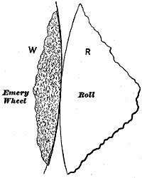
Fig. 684.
This, however, is a theoretical, rather than a practical point, as may be perceived from Fig. 684, in which r is a part of a section of a roll, and w a part of a section of a wheel. Now, assuming that the V-ways were as much as even a sixteenth out of true, so far as height is concerned, all the influence of the variation in height is shown by the second line of emery-wheel perimeter, shown in the figure, the two arcs being drawn from centres, one of which is 1⁄16th inch higher than the other. It is plain, then, that with the ordinary errors found in such V-guideways, which will not be found to exceed 1⁄30th of an inch, no practical effect will be produced upon the roll. Again, if one V is not in line with the other, no practical effect is produced, because if the carriage c were inclined at an angle, though the plane of rotation of the emery-wheel would be varied, its face would yet be parallel to the roll axis. If the Vs were to vary in their widths apart (the angles of the Vs being 45° apart), all the effect it would have would be to raise or lower the carriage c to one-half the amount the Vs were in error. It will be thus perceived that correctness of the roll both for parallelism and cylindricity is obtained independent of absolute truth in the V-guides.
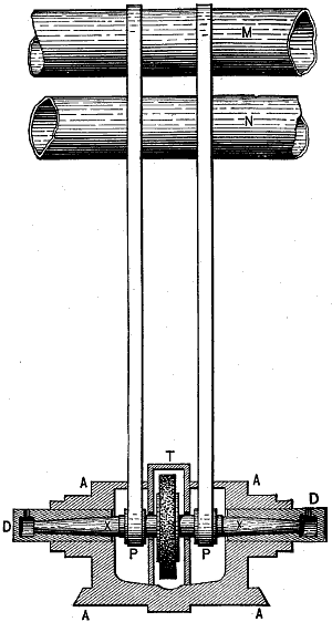
Fig. 685.
Referring now to some of the details of construction of the lathe, the slide rest a, Fig. 683, is bored to receive sockets d d, Fig. 685, and is provided with caps, so that the sockets may be firmly gripped and held axially true one with the other. The socket-bores are taper, to receive the taper ends of the arbor x, and are provided with oil pockets at each end. There is a driving pulley on each side of the emery-wheel, and equal belt-speed is obtained as follows: Two belt driving drums m n are employed, and each belt passes over both, as in Figs. 683 and 685, and down around the pulleys p. The diameter of the drum n is less than the diameter of the drum m by twice the thickness of the belt, thus equalizing inside and outside belt diameters, since they both pass over the pulley of the emery-arbor. The piece t is a guard to catch the water from the emery-wheels, and is hinged at the back so that the top is a lid that may be swung back out of the way when necessary.
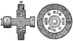
Fig. 686.
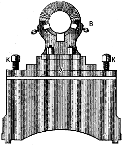
Fig. 687.
The method of securing the emery-wheels is shown in Fig. 686. Two flanges z (made in halves) are let into the wheel, and clamp the wheel by means of the screws shown. The bore of these flanges z is larger than the diameter of pulleys p, so that the emery-wheels may be changed on the arbor without removing the pulley. Fig. 687 represents an end view of the bearings b for the roll to revolve in, being provided with three pieces, the two side ones of which are adjustable by the set-screws, so as to facilitate setting the roll parallel with the bed of the lathe. The height is adjusted by means of screws k, k, which may also be used in grinding a roll of large diameter at the middle of its length, by occasionally raising the roll as the carriage c proceeds along the roll (the principle of this action is hereafter explained with reference to turning tapers on ordinary lathe work). When the wheels have traversed half the length of the roll, the screws k are operated to lower it again, it being found that the effect of a slight operating of the screws k is so small that the workman’s judgment may be relied upon to use them to give to a roll with practical accuracy any required degree of enlarged diameter at the middle of its length with sufficient accuracy for all practical purposes.
There are, however, other advantages of this system, which may be noted as follows. When a single emery-wheel is used there is evidently twice the amount of wear to take a given amount of metal off (per traverse) that there is when two wheels are used, and furthermore the reduction of every wheel diameter per traverse is evidently twice as great with one wheel as it is with two. From some experiments made by Messrs. Morton Poole, it was found that using a pair of 10-inch emery-wheels it would take 40,000 wheel traverses along an average sized calender roll, to reduce its diameter an inch, hence the amount of error due to the reduction of the emery-wheel diameters, per traverse, may be stated as 1⁄40000 of an inch per traverse, for the two wheels.
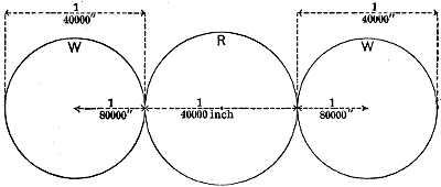
Fig. 688.
Now referring to Fig. 688, let r represent a roll and w w the two emery-wheels.
Suppose the wheels being at the end of a traverse, the roll is 1⁄40000 inch larger at that end on account of the wear of the emery-wheels, then each wheel will have worn 1⁄40000 inch diameter or 1⁄80000 inch radius, hence the increase of roll diameter is equal to the wear of wheel diameter.
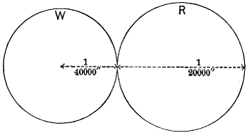
Fig. 689.
Now, suppose that one wheel be used as in Fig. 689, and its reduction of diameter will be equal to that of the two wheels added together, or 1⁄20000 inch, this would be 1⁄40000 in the radius of the wheel, producing a difference of 1⁄20000 difference in the diameter of the wheel.
There is another advantage, however, in that a finer cut can be easier put on in the Poole system, because if a feed be put on of 1⁄100th inch, the roll is only reduced 1⁄100th inch in diameter, but if the same amount of feed be put on with a single wheel, it will reduce the roll 1⁄50th inch, hence for a given amount of feed or movement of emery-wheel towards the roll axis, the amount of cut taken is only half as much as it would be if a single wheel is used. This enables a minimum of feed to be put on the wheel, wear being obviously reduced in proportion as the feed is lighter and the duty therefore diminished.
The method of driving the roll is as follows: Shaft t, Fig. 681, runs in bearings in the head, and spindle r r′ passes through, and is driven by shaft t. A driving pulley is fitted on the spindle at end r′, at the other end is a driving chuck p for driving the roll through the medium of a wabbler, whose construction will be shown presently. Spindle r may be adjusted endwise in t, so that it may be adjusted to suit different lengths of rolls without moving the bearing blocks b.
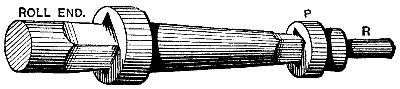
Fig. 690.
The wabbler is driven by p and receives the end of the roll to be ground, as shown in Fig. 690, the end of the roll being a taper square and fitting very loosely in a square taper hole in the end of the wabbler; similarly p may have a taper square hole loosely fitting the squared end of the wabbler. The looseness of fit enables the wabbler to drive the roll without putting any strain on it tending to lift or twist it in its bearings in block b, and obviates the necessity for the axis of the rolls to be dead in line with the axis of r r′. Various lengths of wabblers may be used to suit the lengths of roll and avoid moving blocks b, and it is obvious also that if the ends of the roll are round instead of square, two set-screws may be used to hold the roll end being set diametrically opposite, and if set screws are used in p to drive the wabbler they should be two in number, set diametrically opposite, and at a right angle to the two in the wabbler, so that it may act as a universal joint.
The method of automatically traversing the carriage c is as follows: Referring to Fig. 681, two gears a, b are fast upon shaft t, gear a drives c which is on the same shaft as e, gear b drives d which drives a gear not seen in the cut, but which we will term x, it being on the same shaft as c and e. Now if e is driven through the medium of a c, it runs in one direction, while if it is driven through the medium of b d x, it revolves e in the opposite direction, and since e drives g and g is on the end of the feed screw (e, Fig. 682) the direction of motion of carriage c is determined by which of the wheels a or b drives e. At h is a stand affording journal bearing to a shaft n, whose end engages a clutch upon the shaft of wheels c, x and e. On the outer end of shaft n is ball lever l′′, whose lower end is attached to a rod k, upon which are stops l l′ adjustable along rod k by means of set-screws. At m is a bracket embracing rod k.
Now suppose carriage c to traverse to the left, and m will meet l moving rod k to the left, the ball i will move up to a vertical position and then fall over to the right, causing the clutch to disengage from gear c and engage with the unseen gear x, reversing the motion of e and of g, and therefore of carriage c, which moves to the right until m meets l′ and pushes it to the right, causing i to move back to the position it occupies in the engraving, the clutch engaging c, which is then the driving wheel for e.
Screw Machine.—The screw machine is a special form of lathe in which the work is cut direct from the bar, without the intervention of forging operations, and it follows therefore that the bar must be large enough in diameter to suit the largest diameter of the work, the steps or sections of smaller diameter being turned down from the full size of the bar. The advantages of the screw machine are, that the work requires no centring since it is held in a chuck, that forging operations are dispensed with, that any number of pieces may be made of uniform dimensions without any measuring operations save those necessary when adjusting the tool for the first piece, and that it does not require skilled labor to operate the machine after the tools are once set.
The capacity of the screw machine is, therefore, many times greater than that of a lathe, while the diameters and lengths of the various parts of the work will be more uniform than can be done by caliper measurements, being in this case varied by the wear of the cutting edges of the tools only, which eliminates the errors liable to independent caliper measurement. Hollow work, as nuts and washers, may be equally operated on being driven by a mandril held in the chuck.
VOL. I. EXAMPLES OF SCREW MACHINES. PLATE X.
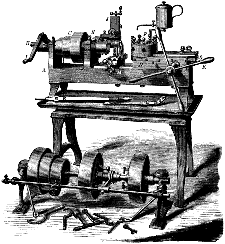
Fig. 691.
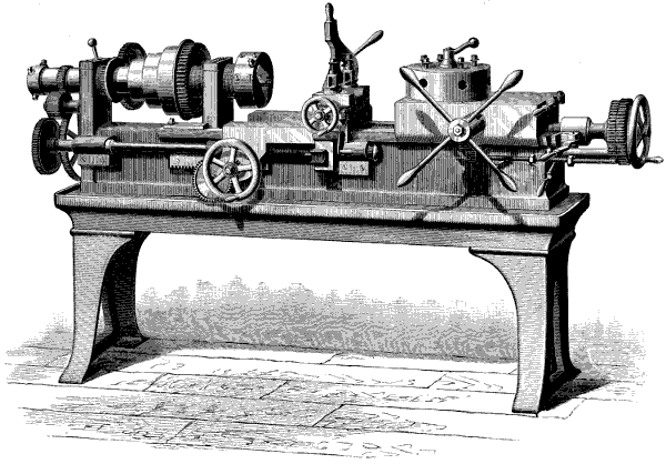
Fig. 692.
Fig. 691 represents Brown and Sharpe’s Number 1 screw machine, which is designed for the rapid production of small work.
Three separate tool-holding devices may be employed: first, cutting tools may be placed in the holes shown to pierce (horizontally) the circular head f; second, tools may be fixed in the tool posts shown in the double slide rest, which has two slides (one in the front and one at the back of the line of centres); and third, tools may be placed in what may be termed the screw-cutting slide-rest j.
f is a head pierced horizontally with seven holes, and is capable of rotation upon l; when certain mechanism is operated l slides on d and the mechanism of these three parts is arranged to operate as follows. The lever arms k traverse l in d. When k is operated from right to left, l advances towards the live spindle until arrested at some particular point by a suitable stop motion, this stop motion being capable of adjustment so as to allow f to approach the live spindle a distance suitable for the work in hand.
When, however, k is operated from left to right l moves back, and when it has traversed a certain distance, the head f rotates 1⁄7 of a rotation, and becomes again locked so far as rotation is concerned. Now the relation between the seven holes in f is such that when f has rotated its 1⁄7 rotation, one of the seven holes is in line with the live spindle. Suppose then seven cutting tools to be secured in the holes in f, then k may be operated from right to left, traversing l and f forward, and one of the cutting tools will operate upon the work until l meets the stop; k may then be moved from left to right, l and f will traverse back, then f will rotate 1⁄7 rotation and l and f may be traversed by k, and a second tool will operate upon the work, and so on.
The diameter of the work is determined by the distance of the cutting edge of the tool from the line of centres, when such tool is in line with the work, or, in other words, is in position to operate upon the work. The end measurements of the work are secured by placing the cutting edges of the tools the requisite distance out from f, when l is moved forward as far as the stop motion will permit. But it is evident that the length of cut taken along the work, would under these simple conditions vary with the distance of the end of the work from the face of the chuck driving it, but this is obviated as follows:—
The live spindle is made hollow so that the rod of metal, of which the work is to be made, may pass through that spindle. A chuck on the spindle holds the work or releases it in the usual manner. Suppose then the chuck to be open and the bar free to be moved, then there is placed in the hole in f, that is in line with the work, a stop instead of a cutting tool. The end of the work may then, for the first piece turned, be squared up by a tool placed in the slide rest and then released from the chuck and pushed through the live spindle until it abuts against the stop so adjusted and affixed in the hole in f; k may then be operated to act on the work. The first tool may reduce the work to its largest required diameter, the second turn down a plain shoulder, the third may be a die cutting a thread a certain distance up the work, the fourth may be a tool turning a plain part at the beginning of the thread, the fifth may round off the end of the work, and the sixth may be a drill to pierce a hole a certain distance up the end of the work.
Now suppose the work to require its edge at the other end to be chamfered, then there may be placed in the slide rest tool posts a tool to sever the work from the bar out of which it has been made, while the other may be used to chamfer the required edge, or to round it if needs be to any required form.
Work held in the chuck but not formed from a rod may be, of course, operated upon in a similar manner.
In the case, however, of work of large diameter requiring to be threaded, the threading tool may be held and operated differently and more rigidly as follows. i is a lever carrying under its bend and over the projecting end of the live spindle, a segment of a nut whose thread must equal in pitch the pitch of thread to be given to the work. A collar or ring, oftentimes called the leader, having a thread of the same pitch, is then secured upon the live spindle, so as to rotate with it, and have no end motion; when therefore i is depressed, the nut will come into work with the collar or ring, and i will be traversed at a speed proportioned to the pitch of the threads on the collar and nut.
Now i is attached to a shaft having journal bearing (and capable of end motion) at the back of the lathe head, and on this bar is attached the slide rest j, in which the turning or threading tool may be placed. The shaft above referred to having end motion, may be operated (when the nut in the lever i is lifted clear of the collar) laterally by means of the lever i; hence to traverse j to the right, or for the back traverse, i is raised and pulled to the right, i is then lowered, the nut engages with the collar, and the tool is traversed to the cut. The cut is adjusted for diameter by the slide rest, which is provided with an adjustable stop to determine the depth to which the tool shall enter the work.
It is obvious that this part of the machine, may be employed for ordinary turning operations, if the collar be of suitable pitch for the feed.
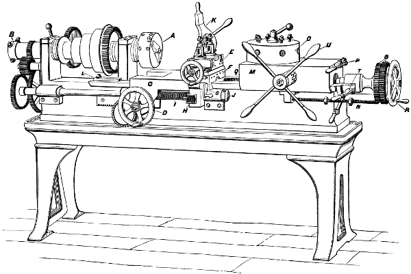
Fig. 693.
Figs. 692 and 693 represent a screw machine for general work.
a is a chuck with hardened steel V-shaped jaws. It is fast on the hollow arbor of the machine. b is a steadying chuck on the rear end of the arbor. The arbor has a two and one-sixteenth hole through it and its journals are very large and stiff. It is of steel, and runs in gun-metal boxes. The cone pulley and back gear is of the full proportion and power of an eighteen-inch lathe. c is an ordinary lathe carriage fitted to slide on the bed, and be operated by hand-wheel d and a rack pinion as usual. Across this carriage slides a tool rest e operated by screw as usual, and having two tool posts, one to the front and one to the rear of the work. This tool rest, instead of sliding directly in the carriage as is the case with lathes, slides on an intermediate slide which fits and slides in the carriage. This intermediate slide is moved in and out, a short distance only, by means of cam lever g. An apron on the front end of this slide carries the lead screw nut h. When the cam lever is raised it brings the slide outward about half an inch, and the tool rest e comes out with it and at the same time the nut leaves the lead screw. The inward movement of the slide is always to the same point, thus engaging the lead screw and resetting the tool. In cutting threads with a tool in the front tool post the tool is set by moving the tool rest as usual, and at the end of the cut the cam lever serves to quickly withdraw the tool and lead screw nut so that the carriage can be run back. The tool rest is then advanced slightly and the new cut taken. By this means threads are cut without any false motions, and the threads may be cut close up to a shoulder.
i is the lead screw. This screw does not extend, as is usual, to the head of the machine. It is short and is socketed into a shaft which runs to the head of the machine and is driven by gearing as usual. The lead screw is thus a plain shaft with a short, removable, threaded end. The gearing is never changed. Different lead screws are used for different threads, thus permitting threads to be cut without running back. The lead screws are changed in an instant by removing knob j. The lead screw nut h is a sectional nut, double ended, so that each nut will do for two pitches, by turning end for end in the apron. l is an adjustable stop which determines the position of the carriage in cutting off, facing, &c. k is an arm pivoted to the rear of the carriage and carrying three open dies like a bolt cutter head. At m is a block sliding or capable of being fed along the bed. n is a gauge screw attached to this block and provided with two nuts. The stop lever shown in the cut turns up to straddle this screw, and the position of the nuts determines how far each way the block may slide. o is the turret fitted to turn on the block. It has six holes in its rim to receive sundry tools. It can be turned to bring any of these tools into action, and is secured by the lock lever p.
The turret slide is moved quickly by hand, by means of the capstan levers u, which, by an in-and-out motion, also serve to lock the turret at any point. The turret slide is fed, in heavy work, by the crank-wheel r on its tail screw. This tail screw carries, inside the crank-wheel, two gears s, which are driven at different speeds by a back shaft behind the machine. These two gears are loose on the tail screw, and a clutch operated by lever t locks either one to the screw. Both the carriage and turret are provided with oil pots not shown in the cuts.
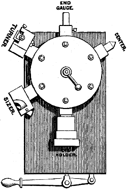
Fig. 694.
A top view of the turret is shown in Fig. 694, a set of tools being shown in place.
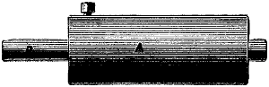
Fig. 695.

Fig. 696.
The end gauge which is shown removed from the chuck in Fig. 695, is composed of a hollow shank a fitting the hole in the turret, and a gauge rod b fitting the bore of the shank. The shank a may be set farther in or out of the turret, and the rod b may be set farther in or out of the shank, the two combined being so set that when the turret is clear back against its stop the end of the rod b will gauge the proper distance that the bar iron requires to project outwards from the chuck of the machine. The centre shown in Fig. 696 corresponds to an ordinary lathe centre, and is only used when chasing long work in steel.
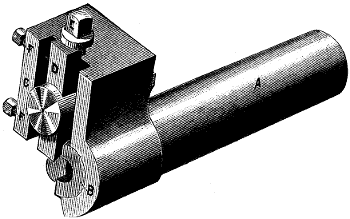
Fig. 697.
The turner shown removed from the chuck in Fig. 697, consists of a hollow shank a, fitting the turret and having at its front end a hardened bushing b secured to a by a set screw. It has also a heavy mortised bolt c in the front lug of the shank; an end-cutting tool d shaped like a carpenter’s mortising chisel, and clamped by the mortised bolt; a collar screw e to hold the tool endwise; and a pair of set-screws f to swivel the tool and its bolt. Bushing b is to suit the work in hand. The tool d is a piece of square steel hardened throughout. It is held by its bolt with just the proper clearance on its face. It cuts with its end without any springing, and will on this account stand a very keen angle of cutting edge. There is hardly any limit to its cutting power. It will cut an inch bar away at one trip with a coarse feed. It does not do smooth work, and is, therefore, used only to remove the bulk of the metal, leaving the sizer to follow.
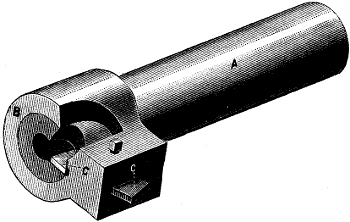
Fig. 698.
The sizer Fig. 698, consists of a hollow shank a fitting the turret and carrying in its front end a hardened bushing b and a flat cutting tool c. The sizer follows the turner and takes a light finishing cut with oil or water, giving size and finish with a coarse feed, and having only a light and clean duty it maintains its size.
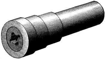
Fig. 699.
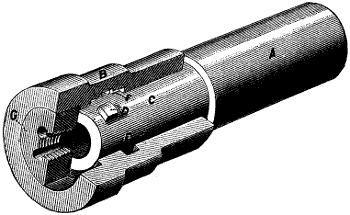
Fig. 700.
The die holder shown in Figs. 699 and 700, is arranged to automatically stop cutting when the thread is cut far enough along the work. It will cut a full thread cleanly up against a solid shoulder. It consists of a hollow shank a fitting the turret; a sleeve b fitted to revolve and slide on the front end of the shank c; a groove e bored inside the sleeve; a pin d on the shank fitting freely in the groove e; a keyway f at one point in the groove and leading out each way from it; and a thread die g held in the front end of the sleeve. When the turret is run forward, the thread die takes hold of the bolt to be cut, but it revolves idly instead of standing still to cut, until the pin d comes opposite the keyway f when, the turret still being moved forward, the pin enters the back of the keyway. The sleeve now stands still, the die cuts the thread and pulls the turret along by the friction of the pin in the keyway. Finally the turret comes against its front stop and can move forward no farther. Consequently the sleeve is drawn forward on its shank c, and the instant the pin d reaches the groove e the die and sleeve commence to revolve with the work and cease cutting. The machine is then run backward, and the turret moved back a trifle. This causes the pin to catch in the front end of the keyway and the sleeve is again locked. The die then unscrews, and, in doing so, pushes the turret back. A tap holder may be inserted in place of the die, and plug taps may be run to an exact depth without danger.
Drills and other boring tools are held in suitable sockets, which fit into the turret.
The following are the operations necessary to produce in this machine an hexagon-headed bolt.
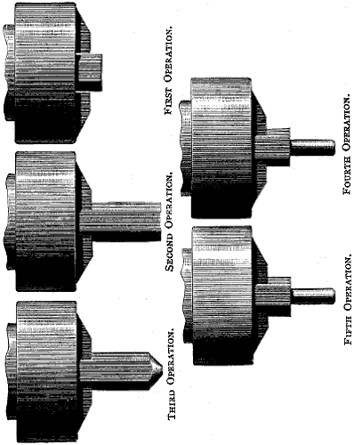
Fig. 701.
First operation: The bar is inserted through the open chuck.
Second operation: Turret being clear back against its stop and revolved to bring present the end gauge, the bar is set against the end gauge, and the chuck is tightened. This chucks the bar and leaves the proper length projecting from the chuck.
Third operation: Front tool in the carriage, a bevelled side tool cones the end of the bar so turret tools will start nicely.
Fourth operation: Turret being revolved to present the turner, the bar is reduced, at one heavy cut, to near the proper size, the turret stop determining the length of the reduced portion.
Fifth operation: Turret being revolved to present the sizer, the body of the bolt is brought to exact size by a light, quick, sliding cut.
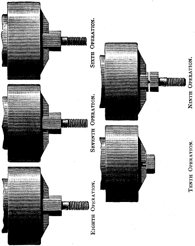
Fig. 702.
Sixth operation: Open die arm being brought down, the bolt is threaded; the left carriage stop indicating the length of the threaded part.
Seventh operation: Turret being revolved to present the die holder, the solid die is run over the bolt, bringing it to exact size with a light cut, and cutting full thread to the exact point desired.
Eighth operation: Front tool in the carriage chamfers off the end thread.
Ninth operation: Back tool of carriage, a parting tool, cuts off the bolt; the left carriage stop determining the proper length of head.
Tenth operation: Bolt being reversed in chuck, the top of the head is water cut finished by a front tool in the carriage. This operation is deferred till all the bolts of the lot are ready for it.
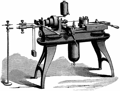
Fig. 703.
Fig. 703 represents a general view of a screw machine designed by Jerome B. Secor, of Bridgeport, Connecticut. The details of the machine are shown in Figs. 704, 705, 706, 707, 708, 709, 710, and 711.[13] The live spindle is of steel and is hollow, and its journals are ground. The boxes are lined with babbitt, so that no other metal touches the spindle, and may, by a special device, be re-babbitted and bored exactly parallel with the planing of the bed.
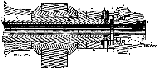
Fig. 704.
A steel collar j, Fig. 704, between the front end of the forward box and the spindles, receives the thrust due to the cut, and a nut on the spindle acts against the cone to adjust it forward on a feather k in the spindle to take up end wear. The wire or rod from which the work is to be made is passed through the spindle and collar on the stand, and is held by a thumb-screw in the collar, which is influenced by the weight and cords, so that when the wire is released in the chuck the weight pulls the collar and wire forward, forcing the wire out through the front end of the chuck until it comes against the stop in the turret, which gauges the length needed to make the piece required. From time to time, as the rod is used up, the thumb-screw in the sliding collar is loosened, and the collar is shoved back on the rod as far as it will go, and the set-screw is again tightened.
Fig. 704 shows in section the front bearing and the automatic chuck. m is a hollow spindle within which is the hollow spindle h, through which the rod or wire to make the work passes. It is prevented from end motion by the cone hub on one side and the collar j on the other side of the bearing, while h may be operated endwise within m by means of the hand-lever shown on the left-hand of the headstock in the general view. The core a of the chuck screws upon m, and is threaded to receive the adjustment nut b, which receives and holds the adjustment wedges c at their ends by the talon shown. The shell d is secured to h by the screws i, which pass through slots in a, and therefore move endwise when h is operated by its hand-lever. Now the mouth of d, against which the adjustment wedges c rest, is coned 21⁄2°, as marked; hence the end motion of d to the left causes c, and therefore f, to approach the axis of the chuck and grip the rod or wire, while its motion to the right causes c, and therefore f, to recede from the chuck axis and to release the wire. Since b is screwed upon a, and c is guided at the end by b, and since also f is detained endwise in a, the motions of c and of f are at a right angle to the chuck axis. Hence in gripping the rod or wire there is no tendency to move it endways, as there is where the gripping jaws have, as in many machines, a certain amount of end motion while closing. When this end motion exists, tightening the jaws upon the work draws it away from the stop in the turret and impairs the adjustment for length of work. The gripping jaws are closely guided in slots in d and in a, and three sets of these jaws are necessary to cover a range of work from the full diameter of the bore of h down to zero. The capacity of each of these sets of jaws, however, may be varied as follows: The adjustment ring b is threaded upon a, and may be operated along a to move c endwise by means of the tangent screw e, whose threads engage with teeth parallel to the axis of b, and running across its width all around its circumference, hence rotating e, rotates b, causing it to move along a, and carry c beneath f. By this method of adjustment f need be given only enough motion to and from the chuck axis to grip and release the work, and the reduction of motion between the hand-lever operating h and the motion of f is so great, that with a very moderate force at the lever the wire may be held so that its projecting end may be twisted off without slipping the wire within the jaws or impairing the jaw grip.
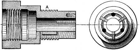
Fig. 705.
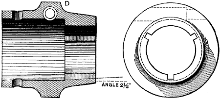
Fig. 706.
Fig. 705 is a sectional and end view of the core a of the chuck, and Fig. 706 a sectional and end view of the shell d.
Large image (83 kB).
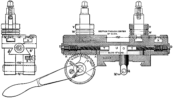
Fig. 707.
Fig. 707 represents a sectional side view and an end view of the cross slide, or cutting-off slide, which carries two tool posts, and therefore two cutting tools, one of which is at the back of the rest. In place of a feed screw and nut, or of a hand lever and link, it is provided with a segment of a gear-wheel p operating in a rack r, which avoids the tendency to twist the cross slides in its guides which exists when a hand lever and link is used.
The cross slide is adjusted to fit in its guideway by a jaw s1, Fig. 707, which is firmly screwed to and recessed into r. To take up the wear, the face of s1 is simply reduced. This possesses a valuable advantage, because it is rigid and solid, does not admit of improper adjustment, nor can the adjustment become impaired at the hands of the operator.
To adjust the position of the cross slide upon the shears a screw passes between the shears and is threaded into the stud q. This screw is operated by a hand wheel shown in the general view, Fig. 703, beneath the rear bearing of the headstock.
A special and excellent feature of the machine is the stop device for the motion of the cross slide which is shown in Fig. 707.
The screw s has one collar c, solid on it, and the screwed end is tapped into the sliding sleeve t, which is held from turning by the stud a. Between the solid collar c and the loose collar b there is a short, stiff spiral spring, as shown; by means of the fast and loose collars, the spring and the screwed thimble d, a strong friction is had on the collar b, which is ample to keep the screw from turning while in use as a stop, although it permits the screw to turn easily enough when a wrench is applied to the square end. Precisely the same device is used at the other end of the slide to stop it in the opposite direction.
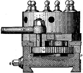
Fig. 708.
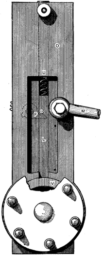
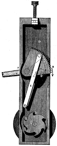
Fig. 709. Fig. 710.
Details of the mechanism of the turret and turret slide are shown in Figs. 708, 709, and 710. Fig. 708 is an end sectional view of the turret slide, which is traversed on its base by a segment d of a gear operating in a rack r (in the same manner as the cutting-off slide), the segment being connected by stud n to handle m. o represents the body of the slide, which is grooved at the sides to receive the gibs x, which secure it to the base p on which it slides. p is clamped to its adjusted position on the shears or bed by means of the gib, shown in dotted lines, which is pulled laterally forward by the screw s, which is tapped into the stem of the gib. The method of rotating the slide and of locking it in position is shown in Fig. 709, which is a top view of the turret head, and Fig. 710, which shows o removed from p and turned upside down. Pivoted to segment d is a rod e having at k a pin that as motion proceeds falls into s and rotates t, which is fast to the bottom of the turret. Upon the handle m being moved backward the segment begins its motion forward, as indicated by the arrow in Fig. 710, thereby moving the slide backward upon the gibs by the working of its cogs into the rack r, Fig. 708, which is attached to the base p. When the segment d has accomplished about one-half its motion the pin h, which is on the upper side of the segment d, comes in contact with the projection or lug on the side of the cam f, as shown by the arrow head in Fig. 710, bringing the opposite side of the cam against the pin g, Fig. 709, thereby moving it backward, compressing the spring u, and drawing the bolt l from its seat in the disc v. This operation is completed before the motion of the segment brings the pin k in contact with the ratchet-wheel t. The segment d in continuing its motion after the pin k is brought into the notch s, begins the revolution of the turret on its axis. As will be seen by the inspection of Fig. 710, the pin h works upon a much longer radius than the projection upon the cam with which it comes in contact, and therefore, after a given part of its motion is complete, gets beyond the reach of the cam, thereby releasing its hold and allowing the bolt l, Fig. 709, to be forced against the disc v by the expansion of the spring u, which occurs soon after the turret has commenced its revolution by the contact of pin k with the wheel t. The completion of the movement of the handle m (and the segment d) completes the revolution of the turret one-sixth of its circumference, thereby allowing the bolt l, by the further expansion of the spring u, to be forced into its next opening or seat in the disc v. The forward motion of the handle m brings the turret forward to its position at the work and restores the parts to their former positions, as shown in the illustrations.
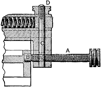
Fig. 711.
The stop motion for the forward motion of m, and that therefore determines the length of turret traverse forward, and hence the distance each tool shall carry its cut along the work, is shown in Fig. 711. The end of the screw a abuts against the stop b in the usual manner; it is, however, threaded through the eye of a bolt c, as well as through the end of the turret slide, so that it may be locked by simply operating the nut d. Thus the use of a wrench is obviated, and the adjustment is more readily effected.
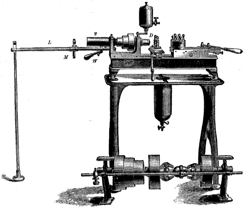
Fig. 712.
Large image (92 kB).
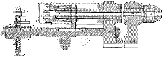
Fig. 713.
Figs. 712 and 713 represent a screw machine by the Pratt and Whitney Company, of Hartford, Connecticut, and having Parkhurst’s patent wire or rod feed for moving the work through the hollow spindle and into position to be operated upon by the tools. The reference letters correspond in both figures.
At a is the front and at b the back bearing, affording journal bearing to a hollow spindle c, which carries the shell d of the work-gripping chuck, the clutch ring h and a collar i, in which is pivoted, at j, the clutch levers g. This collar is threaded upon c and is locked in position by a ring lock nut j′. The clutch arm k slides upon a rod x, and has a feather projecting into a spline in x. The core e of the work-gripping chuck is fast upon the inner spindle f, which revolves with the outer one c. The left-hand end of f abuts against the short arms of the clutch levers g, and it is obvious that when k is operated back and forth upon x, it moves the clutch h endways upon c, and the cone upon h operates the levers g, causing them to move the inner spindle f endways and the inner cone e of the chuck to open or close. Suppose, for example, that k (and hence h) is moved to the right, and the long ends of g will be released and may close moving their short ends away from the end of f, and therefore releasing e from its grip upon the work. In moving k to the right the sleeve l is also moved to the right, and its serrations at l′ being engaged with the tongue p, the sleeve m is pulled forward. Now the bar or rod of which the work is made is held at one end by the chuck, it is supported by the bushing z in the end of spindle c, and in the bushing s in the arm of sleeve m, while it has fast upon it a collar t. When therefore m is pulled forward or to the right, its arm meets t and pulls the rod or bar for the work through the chuck e.
On the other hand when k and therefore h, l, and m, are moved to the left, levers g are opened at their long ends by the cone of h. The short ends of g push the inner spindle f to the right, e passes through d, and being split, closes upon the work and grips it, the parts occupying the positions shown in the figure. The same motion of k passes l through the sleeve m (the teeth at n raise the catch p, allowing l′ to pass through m) so that at the next movement of k to the right, m will be pulled a second step forward, again passing the work through the chuck. q is merely a pin wherewith to lift p and enable m to be moved back, when putting in a new rod for the work; k is operated by a link from u to v, the handle for moving this link being shown at w in the general view.
To prevent the sleeve m from moving back with l it is provided with a shoe o, pressed by the spring r against x, thus producing a friction between m and x that holds m while l slides through it. r′ is to regulate the tension of the spring at r. y is merely a sleeve to protect the clutch mechanism from dust, &c.
Box tools for screw machines are used for a great variety of special work. They are simply boxes or heads carrying tools and a work-steadying rest.
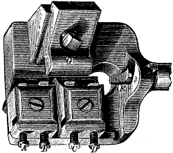
Fig. 714.
Fig. 714 represents a box tool for a screw machine. The cylindrical stem fits into the turret holes and contains a steadying piece or rest g to support the work and keep it to its cut. In the box tool shown in the figure, there are four cutting tools set in to the depth of cut by the screws a, b, c, and d respectively, and a fifth for rounding off the end of the work is shown at e.
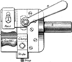
Fig. 715.
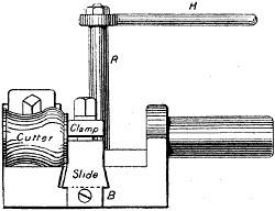
Fig. 715a.
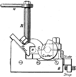
Fig. 715b.
Fig. 715 represents a top view, Fig. 715a a front view, and Fig. 715b an end view, of a box tool for shaping the handles for the wheels of the feeding mechanism of machines. The work is first turned true and to its required diameter, and the rest is set to just bear against the work to steady it and hold it against the pressure of the cut. The cutter is cylindrical with a gap cut in it at g, so as to give a cutting edge. By grinding the face of this gap the tool is sharpened without altering its shape, as is explained with reference to circular or disc tools for lathe work. The cutter is provided with a stem by which it is held in the slide, through the medium of the clamp. The slide is operated by an eccentric on the spindle or rod r, which is operated by the handle h. The stop obviously arrests the motion of the slide when it meets the box b, and this determines the diameter of the work, which is represented by w in the end view figure.