Volume 1 — Chapter IV.—SCREW THREAD.
Reading edition
Screw threads are employed for two principal purposes—for holding or securing, and for transmitting motion. There are in use, in ordinary machine shop practice, four forms of screw thread. There is, first, the sharp V-thread shown in Fig. 246; second, the United States standard thread, the Sellers thread, or the Franklin Institute thread, as it is sometimes called—all three designations signifying the same form of thread. This thread was originally proposed by William Sellers, and was afterward recommended by the Franklin Institute. It was finally adopted as a standard by the United States Navy Department. This form of thread is shown in Fig. 247. The third form is the Whitworth or English standard thread, shown in Fig. 248. It is sometimes termed the round top and bottom thread. The fourth form is the square thread shown in Fig. 249, which is used for coarse pitches, and usually for the transmission of motion.
The sharp V-thread, Fig. 246, has its sides at an angle of 60° one to the other, as shown; or, in other words, each side of the thread is at an angle of 60° to the axial line of the bolt. The United States Standard, Fig. 247, is formed by dividing the depth of the sharp V-thread into 8 equal divisions and taking off one of the divisions at the top and filling in another at the bottom, so as to leave a flat place at the top and bottom. The Whitworth thread, Fig. 248, has its sides at an angle of 55° to each other, or to the axial line of the bolt. In this the depth of the thread is divided into 6 equal parts, and the sides of the thread are joined by arcs of circles that cut off one of these parts at the top and another at the bottom of the thread. The centres from which these arcs are struck are located on the second lines of division, as denoted in the figure by the dots. Screw threads are designated by their pitch or the distance between the threads. In Fig. 250 the pitch is 1⁄4 inch, but it is usual to take the number of threads in an inch of length; hence the pitch in Fig. 250 would generally be termed a pitch of 4, or 4 to the inch. The number of threads per inch of length does not, however, govern the true pitch of the thread, unless it be a “single” thread.
A single thread is composed of one spiral projection, whose advance upon the bolt is equal in each revolution to the apparent pitch. In Fig. 251 is shown a double thread, which consists of two threads. In the figure, a denotes one spiral or thread, and b the other, the latter being carried as far as c only for the sake of illustration. The true pitch is in this case twice that of the apparent pitch, being, as is always the case, the number of revolutions the thread makes around the bolt (which gives the pitch per inch), or the distance along the bolt length that the nut or thread advances during one rotation. Threads may be made double, treble, quadruple and so on, the object being to increase the motion without the use of a coarser pitch single thread, whose increased depth would weaken the body of the bolt.
The “ratchet” thread shown in Fig. 252 is sometimes used upon bolts for ironwork, the object being to have the sides a a of the thread at a right angle to the axis of the bolt, and therefore in the direct line of the strain. Modifications of this form of thread are used in coarse pitches for screws that are to thread direct into woodwork.
A waved or drunken thread is one in which the path around the bolt is waved, as in Fig. 253, and not a continuous straight spiral, as it should be. All threads may be either left hand or right, according to their direction of inclination upon the bolt; thus, Fig. 254 is a cylinder having a right-hand thread at a and a left-hand one at b. When both ends of a piece have either right or left-hand threads, if the piece be rotated and the nuts be prevented from rotating, they will move in the same direction, and, if the pitches of the threads are alike, at the same rate of motion; but if one thread be a right and the other a left one, then, under the above conditions, the nuts will advance toward or recede from each other according to the direction of rotation of the male thread.
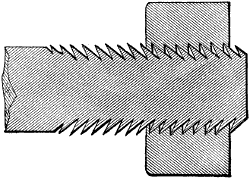
Fig. 255.
In Fig. 255 is represented a form of thread designed to enable the nut to fit the bolt, and the thread sides to have a bearing one upon the other, notwithstanding that the diameter of the nut and bolt may differ. The thread in the nut is what may be termed a reversed ratchet thread, and that in the bolt an undercut ratchet thread, the amount of undercut being about 2°. Where this form of thread is used, the diameter of the bolt may vary as much as 1⁄32d of an inch in a bolt 3⁄4 inch in diameter, and yet the nut will screw home and be a tight fit. The difference in the thread fit that ordinarily arises from differences in the standards of measurement from wear of the threading tools, does not in this form affect the fit of the nut to the bolt. In screwing the nut on, the threads conform one to the other, giving a bearing area extending over the full sides of the thread. The undercutting on the leading face of the bolt thread gives room for the metal to conform itself to the nut thread, which it does very completely. The result is that the nut may be passed up and down the bolt several times and still remain too tight a fit to be worked by hand. Experiment has demonstrated that it may be run up and down the bolt dozens of times without becoming as loose as an ordinary bolt and nut. On account of this capacity of the peculiar form of thread employed, to adapt itself, the threads may be made a tight fit when the threading tools are new. The extra tightness that arises from the wear of these tools is accommodated in the undercutting, which gives room for the thread to adjust itself to the opposite part or nut.
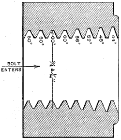
Fig. 256.
In a second form of self-locking thread, the thread on the bolt is made of the usual V-shape United States standard. The thread in the nut, however, is formed as illustrated in Fig. 256, which is a section of a 3⁄4-inch bolt, greatly enlarged for the sake of clearness of illustration. The leading threads are of the same angle as the thread on the bolt, but their diameters are 3⁄4 and 1⁄16th inch, which allows the nut to pass easily upon the bolt. The angle of the next thread following is 56°, the succeeding one 52°, and so on, each thread having 4° less angle than the one preceding, while the pitch remains the same throughout. As a result, the rear threads are deeper than the leading ones. As the nut is screwed home, the bolt thread is forced out or up, and fills the rear threads to a degree depending upon the diameter of the bolt thread. For example, if the bolt is 3⁄4 inch, its leading or end thread will simply change its angle from that of 60° to that of 44°, or if the bolt thread is 3⁄4 and 1⁄64th inch in diameter, its leading thread will change from an angle of 60° to one of 44°. It will almost completely fill the loose thread in the nut. The areas of spaces between the nut threads are very nearly equal, although slightly greater at the back end of the nut, so that if the front end will enter at all, the nut will screw home, while the thread fit will be tight, even under a considerable variation in the bolt itself. From this description, it is evident that the employment of nuts threaded in this manner is only necessary in order to give to ordinary bolts all the advantages of tightness due to this form of thread.
The term “diameter” of a thread is understood to mean its diameter at the top of the thread and measured at a right angle to the axis of the bolt. When the diameter of the bottom or root of the thread is referred to it is usually specified as diameter at the bottom or at the root of the thread.
The depth of a thread is the vertical height of the thread upon the bolt, measured at a right angle to the bolt axis and not along the side of the thread.
A true thread is one that winds around the bolt in a continuous and even spiral and is not waved or drunken as is the thread in Fig. 253. An outside or male thread is one upon an external surface as upon a bolt; an internal or female thread is one produced in a bore or hole as in a nut.
The Whitworth or English standard thread, shown in Fig. 248, is that employed in Great Britain and her colonies, and to a small extent in the United States. The V-thread fig. 246 is that in most common use in the United States, but it is being displaced by the United States standard thread. The reasons for the adoption of the latter by the Franklin Institute are set forth in the report of a committee appointed by that Institute to consider the matter. From that report the following extracts are made.
“That in the course of their investigations they have become more deeply impressed with the necessity of some acknowledged standard, the varieties of threads in use being much greater than they had supposed possible; in fact, the difficulty of obtaining the exact pitch of a thread not a multiple or sub-multiple of the inch measure is sometimes a matter of extreme embarrassment.
“Such a state of things must evidently be prejudicial to the best interests of the whole country; a great and unnecessary waste is its certain consequence, for not only must the various parts of new machinery be adjusted to each other, in place of being interchangeable, but no adequate provision can be made for repairs, and a costly variety of screwing apparatus becomes a necessity. It may reasonably be hoped that should a uniformity of practice result from the efforts and investigations now undertaken, the advantages flowing from it will be so manifest, as to induce reform in other particulars of scarcely less importance.
“Your committee have held numerous meetings for the purpose of considering the various conditions required in any system which they could recommend for adoption. Strength, durability, with reference to wear from constant use, and ease of construction, would seem to be the principal requisites in any general system; for although in many cases, as, for instance, when a square thread is used, the strength of the thread and bolt are both sacrificed for the sake of securing some other advantage, yet all such have been considered as special cases, not affecting the general inquiry. With this in view, your committee decided that threads having their sides at an angle to each other must necessarily more nearly fulfil the first condition than any other form; but what this angle should be must be governed by a variety of considerations, for it is clear that if the two sides start from the same point at the top, the greater the angle contained between them, the greater will be the strength of the bolt; on the other hand, the greater this angle, supposing the apex of the thread to be over the centre of its base, the greater will be the tendency to burst the nut, and the greater the friction between the nut and the bolt, so that if carried to excess the bolt would be broken by torsional strain rather than by a strain in the direction of its length. If, however, we should make one side of the thread perpendicular to the axis of the bolt, and the other at an angle to the first, we should obtain the greatest amount of strength, together with the least frictional resistance; but we should have a thread only suitable for supporting strains in one direction, and constant care would be requisite to cut the thread in the nut in the proper direction to correspond with the bolt; we have consequently classed this form as exceptional, and decided that the two sides should be at an angle to each other and form equal angles with the base.
“The general form of the thread having been determined upon the above considerations, the angle which the sides should bear to each other has been fixed at 60°, not only because this seems to fulfil the conditions of least frictional resistance combined with the greatest strength, but because it is an angle more readily obtained than any other, and it is also in more general use. As this form is in common use almost to the exclusion of any other, your committee have carefully weighed its advantages and disadvantages before deciding to recommend any modification of it. It cannot be doubted that the sharp thread offers us the simplest form, and that its general adoption would require no special tools for its construction, but its liability to accident, always great, becomes a serious matter upon large bolts, whilst the small amount of strength at the sharp top is a strong inducement to sacrifice some of it for the sake of better protection to the remainder; when this conclusion is reached, it is at once evident a corresponding space may be filled up in the bottom of the thread, and thus give an increased strength to the bolt, which may compensate for the reduction in strength and wearing surface upon the thread. It is also clear that such a modification, by avoiding the fine points and angles in the tools of construction, will increase their durability; all of which being admitted, the question comes up, what form shall be given to the top and bottom of the thread? for it is evident one should be the converse of the other. It being admitted that the sharp thread can be made interchangeable more readily than any other, it is clear that this advantage would not be impaired if we should stop cutting out the space before we had made the thread full or sharp; but to give the same shape at the bottom of the threads would require that a similar quantity should be taken off the point of the cutting tool, thus necessitating the use of some instrument capable of measuring the required amount, but when this is done the thread having a flat top and bottom can be quite as readily formed as if it was sharp. A very slight examination sufficed to satisfy us that in point of construction the rounded top and bottom presents much greater difficulties—in fact, all taps and screws that are chased or cut in a lathe require to be finished or rounded by a second process. As the radius of the curve to form this must vary for every thread, it will be impossible to make one gauge to answer for all sizes, and very difficult, in fact impossible, without special tools, to shape it correctly for one.
“Your committee are of opinion that the introduction of a uniform system would be greatly facilitated by the adoption of such a form of thread as would enable any intelligent mechanic to construct it without any special tools, or if any are necessary, that they shall be as few and as simple as possible, so that although the round top and bottom presents some advantages when it is perfectly made, as increased strength to the thread and the best form to the cutting tools, yet we have considered that these are more than compensated by ease of construction, the certainty of fit, and increased wearing surface offered by the flat top and bottom, and therefore recommend its adoption. The amount of flat to be taken off should be as small as possible, and only sufficient to protect the thread; for this purpose one-eighth of the pitch would seem to be ample, and this will leave three-fourths of the pitch for bearing surface. The considerations governing the pitch are so various that their discussion has consumed much time.
“As in every instance the threads now in use are stronger than their bolts, it became a question whether a finer scale would not be an advantage. It is possible that if the use of the screw thread was confined to wrought iron or brass, such a conclusion might have been reached, but as cast iron enters so largely into all engineering work, it was believed finer threads than those in general use might not be found an improvement; particularly when it was considered that so far as the vertical height of thread and strength of bolt are concerned, the adoption of a flat top and bottom thread was equivalent to decreasing the pitch of a sharp thread 25 per cent., or what is the same thing, increasing the number of threads per inch 33 per cent. If finer threads were adopted they would require also greater exactitude than at present exists in the machinery of construction, to avoid the liability of overriding, and the wearing surface would be diminished; moreover, we are of opinion that the average practice of the mechanical world would probably be found better adapted to the general want than any proportions founded upon theory alone.”
The principal requirements for a screw thread are as follows: 1. That it shall possess a strength that, in the length or depth of a nut, shall be equal to the strength of the weakest part of the bolt, which is at the bottom of the bolt thread. 2. That the tools required to produce it shall be easily made, and shall not alter their form by reason of wear. 3. That these tools shall (in the case of lathe work) be easily sharpened, and set to correct position in the lathe. 4. That a minimum of measuring and gauging shall be required to test the diameter and form of the thread. 5. That the angles of the sides shall be as acute as is consistent with the required strength. 6. That it shall not be unduly liable to become loose in cases where the nut may require to be fastened and loosened occasionally.
Referring to the first, by the term “the strength of a screw thread,” is not meant the strength of one thread, but of so many threads as are contained in the nut. This obviously depends upon the depth or thickness of the nut-piece. The standard thickness of nut, both in the United States and Whitworth systems, as well as in general practice, or where the common V-thread is used, is made equal to the diameter of the top of the thread. Therefore, by the term “strength of thread” is meant the combined strength of as many threads as are contained in a nut of the above named depth. It is obvious, then, when it is advantageous to increase the strength of a thread, that it may be done by increasing the depth of the nut, or in other words, by increasing the number of threads used in computing its strength. This is undesirable by reason of increasing the cost and labor of producing the nuts, especially as the threading tools used for nuts are the weakest, and are especially liable to breakage, even with the present depth of nuts.
It has been found from experiments that have been made that our present threads are stronger than their bolts, which is desirable, inasmuch as it gives a margin for wear on the sides of the threads. But for threads whose nuts are to remain permanently fastened and are not subject to wear, it is questionable whether it were not better for the bolts to be stronger than the threads. Suppose, for instance, that a thread strips, and the bolt will remain in place because the nut will not come off the bolt readily. Hence the pieces held by the bolt become loosened, but not disconnected. If, on the other hand, the bolt breaks, it is very liable to fall out, leaving the piece or pieces, as the case may be, to fall apart, or at least become disconnected, so far as the bolt is concerned. But since threads are used under conditions where the threads are liable to wear, and since it is undesirable to have more than one standard thread, it is better to have the threads, when new, stronger than the bolts.
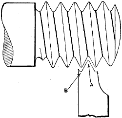
Fig. 257.
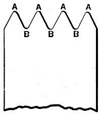
Fig. 258.
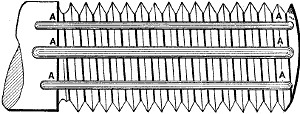
Fig. 259.
Referring to the second requirement, screw threads or the tools that produce them are originated in the lathe, and the difficulty with making a round top and bottom thread lies in shaping the corner to cut the top of the thread. This is shown in Fig. 257, where a Whitworth thread and a single-toothed thread-cutting tool are represented. The rounded point a of the tool will not be difficult to produce, but the hollow at b would require special tools to cut it. This is, in fact, the plan pursued under the Whitworth system, in which a hob or chaser-cutting tool is used to produce all the thread-cutting tools. A chaser is simply a toothed tool such as is shown in Fig. 258. Now, it would manifestly be impracticable to produce a chaser having all the curves, a and b, at the top and at the bottom of the teeth alike, by the grinding operations usually employed in the workshop, and hence the employment of the hob. Fig. 259 represents a hob, which is a threaded piece of steel with a number of grooves such as shown at a, a, a, which divide the thread into teeth, the edges of which will cut a chaser, of a form corresponding to that of the thread upon the hob. The chaser is employed to produce taps and secondary hobs to be used for cutting the threads in dies, &c., so that the original hob is the source from which all the thread-cutting tools are derived.
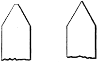
Fig. 260.
For the United States standard or the common V-thread, however, no standard hob is necessary, because a single-pointed tool can be ground with the ordinary grinding appliances of the workshop. Thus, for the United States standard, a flat-pointed tool, Fig. 260, and for the common V-thread, a sharp-pointed tool, Fig. 260, may be used. So far as the correctness of angle of pitch and of thread depth are concerned, the United States standard and the common V-thread can both be produced, under skilful operation, more correctly than is possible with the Whitworth thread, for the following reasons:—
To enable a hob to cut, it must be hardened, and in the hardening process the pitch of the thread alters, becoming, as a general rule (although not always) finer. This alteration of pitch is not only irregular in different threads, but also in different parts of the same thread. Now, whatever error the hob thread receives from hardening it transfers to the chaser it cuts. But the chaser also alters its form in hardening, the pitch, as a general rule, becoming coarser. It may happen that the error induced in the hob hardening is corrected by that induced by hardening the chaser, but such is not necessarily the case.
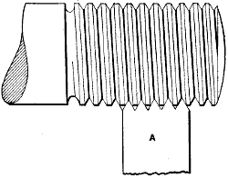
Fig. 261.
The single-pointed tool for the United States standard or for the common V-thread is accurately ground to form after the hardening, and hence need contain no error. On the other hand, however, the rounded top and bottom thread preserves its form and diameter upon the thread-cutting tools better than is the case with threads having sharp corners, for the reason that a rounded point will not wear away so quickly as a sharp point. To fully perceive the importance of this, it is necessary to consider the action of a tool in cutting a thread. In Fig. 261 there is shown a chaser, a, applied to a partly-formed thread, and it will be observed that the projecting ends or points of the teeth are in continuous action, cutting a groove deeper and deeper until a full thread is developed, at which time the bottoms of the chaser teeth will meet the perimeter of the work, but will perform no cutting duty upon it. As a result, the chaser points wear off, which they will do more quickly if they are pointed, and less quickly if they are rounded. This causes the thread cut to be of increased and improper diameter at the root.
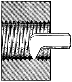
Fig. 262.
The same defect occurs on the tools for cutting internal threads, or threads in holes or bores. In Fig. 262, for example, is shown a tool cutting an internal thread, which tool may be taken to represent one tooth of a tap. Here again the projecting point of the tool is in continuous cutting action, while this, being a single-toothed tool, has no bottom corners to suffer from wear. As a result of the wear upon the tools for cutting internal threads, the thread grooves, when cut to their full widths, will be too shallow in depth, or, more correctly speaking, the full diameter of the thread will be too small to an amount corresponding to twice the amount of wear that the tool point has suffered. In single-pointed tools, such as are used upon lathe work, this has but little significance, because it is the work of but a minute or two to grind up the tool to a full point again, but in taps and solid dies, or in chasers in heads (as in some bolt-cutting machines) it is highly important, because it impairs the fit of the threads, and it is difficult to bring the tools to shape after they are once worn.
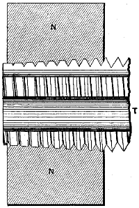
Fig. 263.
The internal threads for the nuts of bolts are produced by a tap formed as at t in Fig. 263. It consists of a piece of steel having an external thread and longitudinal flutes or grooves which cut the thread into teeth. The end of the thread is tapered off as shown, to enable the end of the tap to enter the hole, and as it is rotated and the nut n held stationary, the teeth cut grooves as the tap winds through, thus forming the thread.
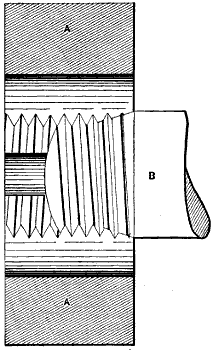
Fig. 264.
The threads upon bolts are usually produced either by a head containing chasers or by a solid die such as shown at a in Fig. 264, b representing a bolt being threaded. The bore of a is threaded and fluted to provide cutting teeth, and the threads are chamfered off at the mouth to assist the cutting by spreading it over several teeth, which enables the bolt to enter the die more easily.
We may now consider the effect of continued use and its consequent wear upon the threads or teeth of a tap and die or chaser.
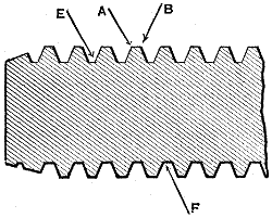
Fi.g 265.
The wear of the corners at the tops of the thread (as at a b in Fig. 265) of a tap is greater than the wear at the bottom corners at e f, because the tops perform more cutting duty.
First, the top has a larger circle of rotation than has the bottom, and, therefore, its cutting speed is greater, to an amount equal to the difference between the circumferences of the thread at the top and at the bottom. Secondly, the tops of the teeth of tap perform nearly all the cutting duty, because the thread in the nut is formed by the tops and sides of the tap, which on entering cut a groove which they gradually deepen, until a full thread is formed, while the bottoms of the teeth (supposing the tapping hole to be of proper diameter and not too small) simply meet the bore of the tapping hole as the thread is finished. If, as in the case of hot punched nuts, the nut bore contains scale, this scale is about removed by the time the bottoms of the top teeth come into action, hence the teeth bottoms are less affected by the hardness of the scale.
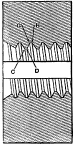
Fig. 266.
In the case of the teeth on dies and chasers, the wear at the corners c d, in Fig. 266, is the greatest. Now, the tops of the teeth on the tap (a b, in Fig. 265) cut the bottom or full diameter of the thread in the nut, while the tops of the teeth (c d, in Fig. 266) in the die cut the bottom of the thread on the bolt; hence the rounded corners cut on the work by the tops of the teeth in the one case, meet the more square corners left by the tops of the teeth in the other, and providing that under these circumstances the thread in the nut were of equal diameter to that on the bolt the latter would not enter the former.
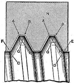
Fig. 267.
If the bolt were made of a diameter to enable the nut to wind a close fit upon the bolt, the corners only of the threads would fit, as shown in Fig. 267, which represents at n a thread in a portion of a nut and at s a portion of a thread upon a tap or bolt, the two threads being magnified and shown slightly apart for clearness of illustration. The corners a, b of the nut are then cut by the corners a b of the tap in Fig. 265, and the corners c, c, d correspond to those cut by the corners c, d of the die teeth in Fig. 266; corners e, f, Fig. 267, are cut by corners c, d, in Fig. 266, and corners g, h are cut by corners g, h in Fig. 266, and it is obvious that the roundness of the corners a, b, c, and d in Fig. 267 will not permit the tops of the thread on the bolt to meet the bottoms of the thread in the nut, but that the threads will bear at the corners only.
So far, however, we have only considered the wear tending to round off the sharp corners of the teeth, which wear is greater in proportion as the corners are sharp, and less as they are rounded or flattened, and we have to consider the wear as affecting the diameters of the male and female thread at their tops and bottoms respectively.
Now, since the tops of the tap teeth wear the most, the diameter of the thread decreases in depth, while, since the tops of the die teeth wear most, the depth of the thread in the die also decreases. The tops of the tap teeth cut the bottom of the thread in the nut and the tops of the die teeth cut the bottoms of the thread upon the bolt.
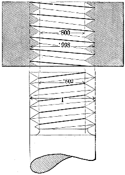
Fig. 268.
Let it be supposed then that the points of the teeth of a tap have worn off to a depth of the 1⁄2000th part of an inch, which they will by the time they become sufficiently dulled to require resharpening, and that the teeth of a die have become reduced by wear by the same amount, and the result will be the production of threads such as shown in Fig. 268, in which the diameter of the bolt is supposed to be an inch, and the proper thread depth 1⁄10th inch. Now, the diameter at the root of the thread on the bolt will be .802 inch in consequence of the wear, but the smallest diameter of the nut thread is .800 inch, and hence too small to admit the male or bolt thread. Again, the full diameter of the bolt thread is 1 inch, whereas the full diameter of the nut thread is but .998 inch, or, again, too small to admit the bolt thread. As a result, it is found in practice that any standard form of thread that makes no allowance for wear, cannot be rigidly adhered to, or if it is adhered to, the tap must be made when new above the standard diameter, causing the thread to be an easy fit, which fit will become closer as the thread-cutting tools wear, until finally it becomes too tight altogether. The fit, however, becomes too tight at the top and bottom, where it is not required, instead of at the sides, where it should occur. When this is the case, the nuts will soon wear loose because of their small amount of bearing area.
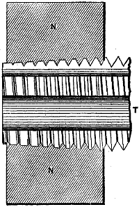
Fig. 269.
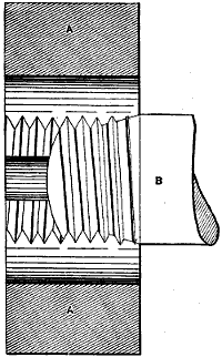
Fig. 270.
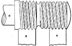
Fig. 271.
It may be pointed out, however, that from the form in which the chasers or solid dies for bolt machines, and also that in which taps are made, the finishing points of the teeth are greatly relieved of cutting duty, as is shown in Figs. 269 and 270. In the die the first two or three threads are chamfered off, while in the tap the thread is tapered off for a length usually equal to about two or three times the diameter for taps to be used by hand, and six or seven times the diameter for taps to be used in a machine. The wear of the die is, therefore, more than that of the tap, because the amount of cutting duty to produce a given length of thread is obviously the same, whether the thread be an internal or an external one, and the die has less cutting edges to perform this duty than the tap has. The main part of the cutting is, it is true, in both cases borne by the beveled surfaces at the top of the chamfered teeth of the cutting tools, but the fact remains that the depth of the thread is finished by the extreme tops of the teeth, and these, therefore, must in time suffer from the consequent wear, while the bottoms of the teeth perform no cutting duty, providing that the hole in the one case and the bolt in the other are of just sufficient diameter to permit of a full thread being formed, as should be the case. In threads cut by chasers the same thing occurs; thus in Fig. 271 is shown at a a chaser having full teeth, as it must have when a full thread is to pass up to a shoulder, as up to the head of a bolt. Here the first tooth takes the whole depth of the cut, but if from wear this point becomes rounded, the next tooth may remedy the defect. When, however, a chaser is to be used upon a thread that terminates in a stem of smaller diameter, as c in Fig. 271, then the chaser may have its teeth bevelled off, as is shown on b.
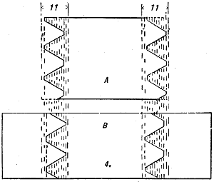
Fig. 272.
The evils thus pointed out as attending the wear of screw-cutting tools for bolts and nuts, may be overcome by a slight variation in the form of the thread. Thus in Fig. 272, at a is shown a form of thread for the tools to cut internal threads, and at b a form of thread for dies to cut external threads. The sides of the thread are in both cases at the same angle, as say, 60°. The depth of the thread, supposing the angle of the sides to meet in a point, is divided off into 11, or any number of equal divisions. For a tap one of these divisions is taken off, forming a flat top, while at the bottom two of these divisions are taken off, or if desirable, 11⁄2 divisions may be taken off, since the exact amount is not of primary importance. On the external thread cutting tool b, as say a solid die, two divisions are taken off at the largest diameter, and one at the smallest diameter, or, if any other proportion be selected for the tap, the same proportion may be selected for the die, so long as the least is taken off the largest diameter of the tap thread, and of the smallest diameter of the die thread.
The diameter of the tap may still be standard to ring or collar gauge, as in the Franklin Institute thread, the angle at the sides being simply carried in a less distance. In the die the largest diameter of the thread has a flat equal to that on the bottom of the tap, while the smallest diameter has a flat equal to that on the tops of the tap teeth, the width or thickness of the threads remaining the same as in the Franklin Institute thread at each corresponding diameter in its depth.
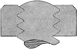
Fig. 273.
The effect is to give to the threads on the work a certain amount of clearance at the top and bottom of the thread, leaving the angles just the same as before, and insuring that the contact shall be at the sides, as shown in Fig. 273.
This form of thread retains the valuable features of the Franklin Institute that it can be originated by any one, and that it can be formed with a single-toothed or single-pointed tool. Furthermore, the wear of the threading tools will not impair the diametral fit of the work, while the permissible limit of error in diameter will be increased.
By this means great accuracy in the diameters of the threads is rendered unnecessary, and the wear of the screw-cutting tools at their corners is rendered harmless, nor can any confusion occur, because the tools for external threads cannot be employed upon internal ones. The sides only of the thread will fit, and the whole contact and pressure of the fit will be on those sides only.
This is an important advantage, because if the tops of the thread are from the wear of the dies and taps of too large or small diameter, respectively, the threads cannot fit on the sides. Thus, suppose a bolt thread to be loose at the sides, but to be 1⁄1000 of an inch larger in diameter than the nut thread, then it cannot be screwed home until that amount has been worn or forced off the thread diameter, or has been bruised down by contact with the nut thread, and it would apparently be a tight fit at the sides. Suppose a thread to have been cut in the lathe to the correct diameter at the bottom of the thread, the sides of the thread being at the correct angle, but let the diameter at the top of the thread (a Franklin Institute thread is here referred to), be 1⁄1000 too large, then the nut cannot be forced on until that 1⁄1000 is removed by some means or other, unless the nut thread be deepened to correspond.
Now take this last bolt and turn the 1⁄1000 inch off, and it will fit, turn off another 1⁄1000 or 1⁄64 inch, and it will still fit, and the fit will remain so nearly the same with the 1⁄64 inch off that the difference can scarcely be found. Furthermore, with a nut of a fit requiring a given amount of force to screw it upon the bolt, the area of contact will be much greater when that contact is on the sides than when it is upon the tops and bottoms of the thread, while the contact will be in a direction better to serve as an abutment to the thrust or strain.
In very fine pitches of thread such as are used in the manufacture of watches, this plan of easing or keeping free the extremities of the thread is found to be essential, and there appears every probability that its adoption would obviate the necessity of using check nuts.
It has been observed that the threads upon tools alter in pitch from the hardening operation, and this is an objection to the employment of chasers cut from hobs.
Suppose, for instance, that a nut is produced having a thread of true and uniform pitch, then after hardening, the pitch may be no longer correct. The chasers cut from the hob will contain the error of pitch existing in the hob, and upon being hardened may have added to it errors of its own. If this chaser be used to produce a new hob, the latter will contain the errors in the chaser added to whatever error it may itself obtain in the hardening. The errors may not, it is true, all exist in one direction, and those of one hardening may affect or correct those caused by another hardening, but this is not necessarily the case, and it is therefore preferable to employ a form of thread that can be cut by a tool ground to correct shape after having been hardened, as is the case with the V-thread and the United States standard.
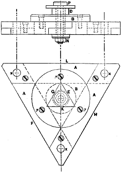
Fig. 274.
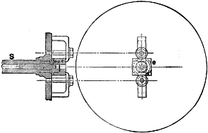
Fig. 275.
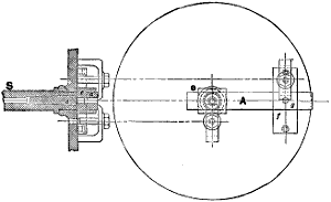
Fig. 276.
It is obvious that in originating either the sharp V or the United States standard thread, the first requisite is to obtain a correct angle of 60°, which has been done in a very ingenious manner by Mr. J. H. Heyer for the Pratt and Whitney Company, the method being as follows. Fig. 274 is a face and an end view of an equilateral triangle employed as a guide in making standard triangles, and constructed as follows:—Three bars, a, a, a, of steel were made parallel and of exactly equal dimensions. Holes x were then pierced central in the width of each bar and the same distance apart in each bar; the method of insuring accuracy in this respect being shown in Figs. 275 and 276, in which s represents the live spindle of a lathe with its face-plate on and a plug, c, fitted into the live centre hole. The end of this plug is turned cylindrically true, and upon it is closely fitted a bush, the plug obviously holding the bush true by its hole. A rectangular piece e is provided with a slot closely fitting to the bush.
The rectangular piece e is then bolted to the lathe face-plate and pierced with a hole, which from this method of chucking will be exactly central to its slot, and at a right angle to its base. The bush is now dispensed with and the piece e is chucked with its base against the face-plate and the hole pierced as above, closely fitting to the pin on the end of the plug c, which, therefore, holds e true.
The bars a are then chucked one at a time in the piece e (the outer end resting upon a parallel piece f), and a hole is pierced near one end, this hole being from this method of chucking exactly central to the width of the bar a, and at a right angle to its face.
The parallel piece f is then provided with a pin closely fitting the hole thus pierced in the bar. The bars were turned end for end with the hole enveloping the pin in f (the latter being firmly fixed to the face-plate), and the other end laid in the slot in e, while the second hole was pierced. The holes (x, Fig. 274) must be, from this method of chucking, exactly an equal distance apart on each bar. The bars were then let together at their ends, each being cut half-way through and closely fitting pins inserted in the holes x, thus producing an equilateral triangle entirely by machine work, and therefore as correct as it can possibly be made, and this triangle is kept as a standard gauge whereby others for shop use may be made by the following process:—
Into the interior walls of this triangle there is fitted a cylindrical bush b, it being obvious that this bush is held axially true or central to the triangle, and it is secured in place by screws y, y, y, passing through its flange and into bars a.
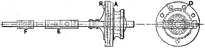
Fig. 277.
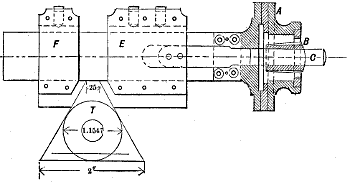
Fig. 278.
At one end of the bush b, is a cylindrical part d, whose diameter is 2 inches or equal to the length of one side of an equilateral triangle circumscribed about a circle whose diameter is 1.1547 inches, as shown in Fig. 278 and through this bush b passes a pin p, having a nut n. A small triangle is then roughed out, and its bore fitting to the stem of pin p, and by means of nut n, the small triangle is gripped between the under face of d and the head of p. The large triangle is then held to an angle-plate upon a machine while resting upon the machine-table, and the uppermost edge of the small triangle is dressed down level with the cylindrical stem d, which thus serves as a gauge to determine how much to take off each edge of the small triangle to bring it to correct dimensions.
The truth of the angles of the small triangle depends, of course, also upon the large one; thus with face h resting upon the machine-table, face g is cut down level with stem d; with face f upon the table, face e is cut down level with d; and with face l upon the table, face k is dressed down level with d. And we have a true equilateral triangle produced by a very ingenious system of chuckings, each of which may be known to be true.
The next operation is to cut upon the small triangle the flat representing the top and bottom of the United States standard thread, which is done by cutting off one-eighth part of its vertical height, and it then becomes a test piece or standard gauge of the form of thread. The next step is to provide a micrometer by means of which tools for various pitches may be tested both for angle and for width of flat, and this is accomplished as follows:—
In Fig. 278 f is a jaw fixed by a set screw to the bar of the micrometer, and e is a sliding jaw; these two jaws being fitted to the edges of the triangle or test piece t in the figure which has been made as already described. To the sliding jaw e is attached the micrometer screw c, which has a pitch of 40 threads per inch; the drum a upon the screw has its circumference divided into 250 equidistant divisions, hence if the drum be moved through a space equal to one of these divisions the sliding jaw e will be moved the 1⁄250th part of 1⁄40th of an inch, or in other words the 1⁄10,000th of an inch. To properly adjust the position of the zero piece or pointer, the test piece t is placed in the position shown in Fig. 278, and when the jaws were so adjusted that light was excluded from the three edges of the test piece, the pointer r, Fig. 277, was set opposite to the zero mark on the drum and fastened.
To set the instrument for any required pitch of thread of the United States standard form the micrometer is used to move the sliding jaw e away from the fixed jaw f to an amount equal to the width of flat upon the top and bottom, of the required thread, while for the sharp V-thread the jaws are simply closed. The gauge being set the tool is ground to the gauge.
VOL. I. MEASURING AND GAUGING SCREW THREADS. PLATE III.
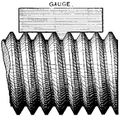
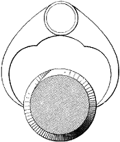
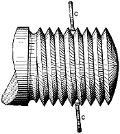
Fig. 279. Fig. 280. Fig. 281.
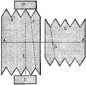
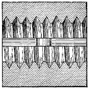
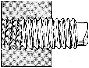
Fig. 282. Fig. 285. Fig. 286.
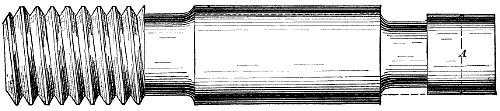
Fig. 283.
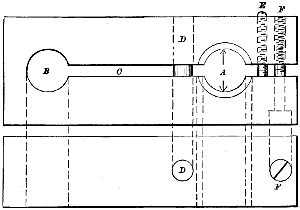
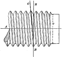
Fig. 284. Fig. 287.
Referring to the third requirement, that the tools shall in the case of lathe work be easily sharpened and set to correct position in the lathe, it will be treated in connection with cutting screws in the lathe. Referring to the fourth requirement, that a minimum of measuring and gauging shall be required to test the diameter and form of thread, it is to be observed that in a Whitworth thread the angle and depth of the thread is determined by the chaser, which may be constantly ground to resharpen without altering the angles or depth of the thread, hence in cutting the tooth the full diameter of the thread is all that needs to be gauged or measured. In cutting a sharp V-thread, however, the thread top is apt to project (from the action of the single-pointed tool) slightly above the natural diameter of the work, producing a feather edge which it becomes necessary to file off to gauge the full diameter of the thread. In originating a sharp V-thread it is necessary first to grind the tool to correct angle; second, to set it at the correct height in the latter, and with the tool angles at the proper angle with the work (as is explained with reference to thread cutting in the lathe) and to gauge the thread to the proper diameter. In the absence of a standard cylindrical gauge or piece to measure from, a sheet metal gauge, such as in Fig. 279, may be applied to the thread; such gauges are, however, difficult to correctly produce.
So far as the diameter of a thread is concerned it may be measured by calipers applied between the threads as in Figs. 280 and 281, a plan that is commonly practised in the workshop when there is at hand a standard thread or gauge known to be of proper diameter; and this method of measuring may be used upon any form of thread, but if it is required to test the form of the thread, as may occur when its form depends upon the workman’s accuracy in producing the single-pointed threading tools, then, in the case of the United States standard thread, the top, the bottom, and the angle must be tested. The top of the thread may (for all threads) be readily measured, but the bottom is quite difficult to measure unless there is some standard to refer it to, to obtain its proper diameter, because the gauge or calipers applied to the bottom of the thread do not stand at a right angle to the axis of the bolt on which the thread is cut, but at an angle equal to the pitch of the thread, as shown in Fig. 282.
Now, the same pitch of thread is necessarily used in mechanical manipulation upon work of widely varying diameters, and as the angle of the calipers upon the same pitch of thread would vary (decreasing as the diameter of the thread increases), the diameter measured at the bottom of the thread would bear a constantly varying proportion to the diameter measured across the tops of the thread at a right angle to the axial line of the work. Thus in Fig. 282, a a is the axial line of two threaded pieces, b, c. d, d represents a gauge applied to b, its width covering the tops of two threads and measuring the diameter at a right angle to a a, as denoted by the dotted line e. The dotted line f represents the measurement at the bottom of the thread standing at an angle to e equal to half the pitch. The dotted line g is the measurement of c at the bottom of the thread.
Now suppose the diameter of b to be 11⁄2 inches at the top of the thread, and 11⁄8 inches at the bottom, while c is 11⁄8 inches on the top and 3⁄4 at the bottom of the thread, the pitches of the two threads being 1⁄4 inch; then the angle of f to e will be 1⁄8 inch (half the pitch) in its length of 11⁄8 inches. The angle of g to e will be 1⁄8 inch (half the pitch) in 3⁄4 (the diameter at the bottom or root of the thread).
It is obvious, then, that it is impracticable to gauge threads from their diameters at the bottom, or root.
On account of the minute exactitude necessary to produce with lathe tools threads of the sharp V and United States standard forms, the Pratt and Whitney Company manufacture thread-cutting tools which are made under a special system insuring accuracy, and provide standard gauges whereby the finished threads may be tested, and since these tools are more directly connected with the subject of lathe tools than with that of screw thread, they are illustrated in connection with such tools. It is upon the sides of threads that the contact should exist to make a fit, and the best method of testing the fit of a male and female thread is to try them together, winding them back and forth until the bright marks of contact show. Giving the male thread a faint tint of paint made of Venetian red mixed with lubricating oil, will cause the bearing of the threads to show very plainly.
Figs. 283 and 284 represent standard reference gauges for the United States standard thread. Fig. 283 is the plug or male gauge. The top of the thread has, it will be observed, the standard flat, while the bottom of the thread is sharp. In the collar, or female gauge, or the template, as it may be termed, a side and a top view of which are shown in Fig. 284, and a sectional end view in Fig. 285, the flat is made on the smallest diameter of the thread, while the largest diameter is left sharp; hence, if we put the two together they will appear as in Fig. 286, there being clearance at both the tops and bottoms of the threads. This enables the diameters of the threads to be in both cases tested by standard cylindrical gauges, while it facilitates the making of the screw gauges. The male or plug gauge is made with a plain part, a, whose diameter is the standard size for the bottoms of the threads measured at a right angle to the axis of the gauge and taking the flats into account. The female gauge or template is constructed as follows:—A rectangular piece of steel is pierced with a plain hole at b, and a standard thread hole at a, and is split through at c. At d is a pin to prevent the two jaws from springing, this being an important element of the construction. e is a screw threaded through one jaw and abutting against the face of the other, while at f is another screw passing through one jaw and threaded into the other, and it is evident that while by operating these two screws the size of the gauge bore a may be adjusted, yet the screws will not move and destroy the adjustment, because the pressure of one acts as a lock to the other. It is obvious that in adjusting the female gauge to size, the thread of the male gauge may be used as a standard to set it by.
To produce sheet metal templates such as was shown in Fig. 279, the following method may be employed, it being assumed that we have a threading tool correctly formed.

Fig. 288.
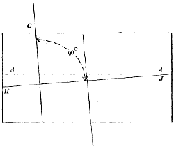
Fig. 289.
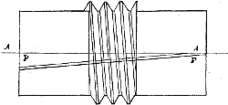
Fig. 290.
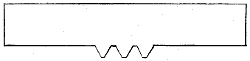
Fig. 291.
Suppose it is required to make a gauge for a pitch of 6 per inch, then a piece of iron of any diameter may be put in the lathe and turned up to the required diameter for the top of the thread. The end of this piece should be turned up to the proper diameter for the bottom of the thread, as at g, in Fig. 287. Now, it will be seen that the angle of the thread to the axis a of the iron is that of line c to line a, and if we require to find the angle the thread passes through in once winding around the bolt, we proceed as in Fig. 288, in which d represents the circumference of the thread measured at a right angle to the bolt axis, as denoted by the line b in Fig. 287. f, Fig. 288 (at a right angle to d), is the pitch of the thread, and line c therefore represents the angle of the thread to the bolt axis, and corresponds to line c in Fig. 287. We now take a piece of iron whose length when turned true will equal its finished and threaded circumference, and after truing it up and leaving it a little above its required finished diameter, we put a pointed tool in the slide-rest and mark a line a a in Fig. 289, which will represent its axis. At one end of this line we mark off below a a the pitch of the thread, and then draw the line h j, its end h falling below a to an amount equal to the pitch of the thread to be cut. The piece is then put in a milling machine and a groove is cut along h j, this groove being to receive a tightly-fitting piece of sheet metal of which a thread gauge is to be made. This piece of sheet metal must be firmly secured in the groove by set-screws. The piece of iron is then again put in the lathe and its diameter finished to that of the required diameter of thread. Its two ends are then turned down to the required diameter for the bottom of the thread, leaving in the middle a section on which a full thread can be cut, as in Fig. 290, in which f f represents the sheet metal for the gauge. After the thread is cut, as in Fig. 290, we take out the gauge and it will appear as in Fig. 291, and all that is necessary is to file off the two outside teeth if only one tooth is wanted.
The philosophy of this process is that we have set the gauge at an angle of 90°, or a right angle to the thread, as is shown in Fig. 289, the line c representing the angle of the thread to the axis a a, and therefore corresponding to the line c in Fig. 287. A gauge made in this way will serve as a test of its own correctness for the following reasons: Taking the middle tooth in Fig. 291, it is clear that one of its sides was cut by one angle and the other by the other angle of the tool that cut it, and as a correctly formed thread is of exactly the same shape as the space between two threads, it follows that if the gauge be applied to any part of the thread that was cut in forming it, and if it fits properly when tried, and then turned end for end and tried again, it is proof that the gauge and the thread are both correct. Suppose, for example, that the tool was correct in its shape, but was not set with its two angles equal to the line of lathe centres, and in that case the two sides of the thread will not be alike and the gauge will not reverse end for end and in both cases fit to the thread. Or suppose the flat on the tool point was too narrow, and the flat at the bottom of the thread will not be like that at the top, and the gauge will show it.
Referring to the fifth requirement, that the angles of the sides of the threads shall be as acute as is consistent with the required strength, it is obvious that the more acute the angles of the sides of the thread one to the other the finer the pitch and the weaker the thread, but on the other hand, the more acute the angle the better the sides of the thread will conform one to the other. The importance of this arises from the fact that on account of the alteration of pitch, already explained, as accompanying the hardening of screw-cutting tools, the sides of threads cut even by unworn tools rarely have full contact, and a nut that is a tight fit on its first passage down its bolt may generally be caused to become quite easy by running it up and down the bolt a few times. Nuts that require a severe wrench force to wind them on the bolt, may, even though they be as large as a two-inch bolt, often be made to pass easily by hand, if while upon the bolt they are hammered on their sides with a hand hammer. The action is in both cases to cause the sides of the thread to conform one to the other, which they will the more readily do in proportion as their sides are more acute. Furthermore, the more acute the angles the less the importance of gauging the threads to precise diameter, especially if the tops and bottoms of the male and female thread are clear of one another, as in Fig. 273.
Referring to the sixth requirement, that the nut shall not be unduly liable to become loose of itself in cases where it may require to be fastened and loosened occasionally, it may be observed, that in such cases the threads are apt from the wear to become a loose fit, and the nuts, if under jar or vibration, are apt to turn back of themselves upon the bolt. This is best obviated by insuring a full bearing upon the whole area of the sides of the thread, and by the employment of as fine pitches as is consistent with sufficient strength, since the finer the pitch the nearer the thread stands at right angle to the bolt axis, and the less the tendency to unscrew from the pressure on the nut face.
The pitches, diameters, and widths of flat of the United States standard thread are as per the following table:—
UNITED STATES STANDARD SCREW THREADS.
Diameter of Screw. Threads per inch. Diameter at root of Thread. Width of Flat.
1⁄4 20 .1850 .0063
5⁄16 18 .2403 .0069
3⁄8 16 .2938 .0078
7⁄16 14 .3447 .0089
1⁄2 13 .4001 .0096
9⁄16 12 .4542 .0104
5⁄8 11 .5069 .0114
3⁄4 10 .6201 .0125
7⁄8 9 .7307 .0139
1 8 .8376 .0156
1 1⁄8 7 .9394 .0179
1 1⁄4 7 1.0644 .0179
1 3⁄8 6 1.1585 .0208
1 1⁄2 6 1.2835 .0208
1 5⁄8 5 1⁄2 1.3888 .0227
1 3⁄4 5 1.4902 .0250
1 7⁄8 5 1.6152 .0250
2 4 1⁄2 1.7113 .0278
The standard pitches for the sharp V-thread are as follows:—
SIZE OF BOLT.
1⁄4 5⁄16 3⁄8 7⁄16 1⁄2 5⁄8 3⁄4 7⁄8 1 11⁄8 11⁄4 13⁄8 11⁄2 15⁄8 13⁄4 17⁄8 2
Number of Threads to Inch.
20 18 16 14 12 11 10 9 8 7 7 6 6 5 5 41⁄2 41⁄2
The following table gives the threads per inch, pitches and diameters at root of thread of the Whitworth thread. The table being arranged from the diameter of the screw as a basis.
Diameter of Screw. Threads per Inch. Pitch. Diameter at Root or Bottom of Thread.
Inch. Inch.
1⁄8 40 .025 .092 9
3⁄16 24 .041 .134 1
1⁄4 20 .050 .185 9
5⁄16 18 .056 .241 3
3⁄8 16 .063 .294 9
7⁄16 14 .071 .346
1⁄2 12 .083 .393 2
9⁄16 12 .083 .455 7
5⁄8 11 .091 .508 5
11⁄16 11 .095 .571
3⁄4 10 .100 .621 9
13⁄16 10 .100 .684 4
7⁄8 9 .111 .732 7
15⁄16 9 .111 .795 2
1 8 .125 .839 9
1 1⁄8 7 .143 .942
1 1⁄4 7 .143 1.067
1 3⁄8 6 .167 1.161 5
1 1⁄2 6 .167 1.286 5
1 5⁄8 5 .200 1.368 8
1 3⁄4 5 .200 1.493 8
1 7⁄8 4 1⁄2 .222 1.590 4
2 4 1⁄2 .222 1.715 4
2 1⁄8 4 1⁄2 .222 1.840 4
2 1⁄4 4 .250 1.929 8
2 3⁄8 4 .250 2.054 8
2 1⁄2 4 .250 2.179 8
2 5⁄8 4 .250 2.304 8
2 3⁄4 3 1⁄2 .286 2.384
2 7⁄8 3 1⁄2 .286 2.509
3 3 1⁄2 .286 2.634
3 1⁄4 3 1⁄4 .308 2.884
3 1⁄2 3 1⁄4 .308 3.106
3 3⁄4 3 .333 3.356
4 3 .333 3.574
4 1⁄4 2 7⁄8 .348 3.824
4 1⁄2 2 7⁄8 .348 4.055
4 3⁄4 2 3⁄4 .364 4.305
5 2 3⁄4 .364 4.534
5 1⁄4 2 5⁄8 .381 4.764
5 1⁄2 2 5⁄8 .381 5.014
5 3⁄4 2 1⁄2 .400 5.238
6 2 1⁄2 .400 5.488
The standard degree of taper, both for the taps and the dies, is 1⁄16 inch per inch, or 3⁄4 inch per foot, for all sizes up to 10-inch bore.
The sockets or couplings, however, are ordinarily tapped parallel and stretched to fit the pipe taper when forced on the pipe. For bores of pipe over 10 inches diameter the taper is reduced to 3⁄8 inch per foot. The pipes or casings for oil wells are given a taper of 3⁄8 inch per foot, and their couplings are tapped taper from both ends. There is, however, just enough difference made between the taper of the socket and that of the pipe to give the pipe threads a bearing at the pipe end first when tried with red marking, the threads increasing their bearing as the pieces are screwed together.
The United States standard thread for steam, gas and water pipe is given below, which is taken from the Report of the Committee on Standard Pipe and Pipe Threads of The American Society of Mechanical Engineers, submitted at the 8th Annual Meeting held in New York, November-December, 1886.
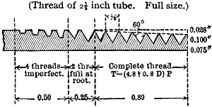
Fig. 291a.
“A longitudinal section of the tapering tube end, with the screw-thread as actually formed, is shown full size in Fig. 291a for a nominal 21⁄2 inch tube, that is, a tube of about 21⁄2 inches internal diameter, and 27⁄8 inches actual external diameter.
“The thread employed has an angle of 60°; it is slightly rounded off both at the top and at the bottom, so that the height or depth of the thread, instead of being exactly equal to the pitch, is only four fifths of the pitch, or equal to 0.8 × 1/n if n be the number of threads per inch. For the length of tube end throughout which the screw thread continues perfect, the empirical formula used is (0.8D + 4.8) × 1/n, where D is the actual external diameter of the tube throughout its parallel length, and is expressed in inches. Further back, beyond the perfect threads, come two having the same taper at the bottom, but imperfect at the top. The remaining imperfect portion of the screw thread, furthest back from the extremity of the tube, is not essential in any way to this system of joint; and its imperfection is simply incidental to the process of cutting the thread at a single operation.”
The standard thicknesses of the pipes and pitches of thread are as follows:—
STANDARD DIMENSIONS OF WROUGHT IRON WELDED TUBES.
DIAMETER OF TUBE. THICKNESS OF METAL. SCREWED ENDS.
Nominal Inside. Actual Inside. Actual Outside. Number of Threads per Inch. Length of Perfect Screw.
Inches. Inches. Inches. Inch. No. Inch.
1⁄8 0.270 0.405 0.068 27 0.19
1⁄4 0.364 0.540 0.088 18 0.29
3⁄8 0.494 0.675 0.091 18 0.30
1⁄2 0.623 0.840 0.109 14 0.39
3⁄4 0.824 1.050 0.113 14 0.40
1 1.048 1.315 0.134 11 1⁄2 0.51
1 1⁄4 1.380 1.660 0.140 11 1⁄2 0.54
1 1⁄2 1.610 1.900 0.145 11 1⁄2 0.55
2 2.067 2.375 0.154 11 1⁄2 0.58
2 1⁄2 2.468 2.875 0.204 8 0.89
3 3.067 3.500 0.217 8 0.95
3 1⁄2 3.548 4.000 0.226 8 1.00
4 4.026 4.500 0.237 8 1.05
4 1⁄2 4.508 5.000 0.246 8 1.10
5 5.045 5.563 0.259 8 1.16
6 6.065 6.625 0.280 8 1.26
7 7.023 7.625 0.301 8 1.36
8 8.982 8.625 0.322 8 1.46
9 9.000 9.688 0.344 8 1.57
10 10.019 10.750 0.366 8 1.68
The taper of the threads is 1⁄16 inch in diameter for each inch of length or 3⁄4 inch per foot.
WHITWORTH’S SCREW THREADS FOR GAS, WATER, AND HYDRAULIC IRON PIPING.
Note.—The Internal and External diameters of Pipes, as given below, are those adopted by the firm of Messrs. James Russell & Sons, in Pipes of their manufacture.
Gas and Water Piping. Hydraulic Piping.
Internal Diameter of Pipe. External Diameter of Pipe. No. of Threads per Inch. Internal Diamter of Pipe. External Diameter of Pipe. Pressure in lbs. per Square Inch. No. of Threads per Inch. Internal Diamter of Pipe. External Diameter of Pipe. Pressure in lbs. per Square Inch. No. of Threads per Inch.
1⁄8 .385 28 1⁄4 - 5⁄8 4,000 - 14 1 1⁄4 - 1 3⁄4 4,000 - 11
1⁄4 .520 19 3⁄4 6,000 1 7⁄8 6,000
3⁄8 .665 19 7⁄8 8,000 2 8,000
1⁄2 .822 14 1 10,000 2 1⁄8 10,000
3⁄4 1.034 14 3⁄8 - 3⁄4 4,000 - 14 1 3⁄8 - 1 7⁄8 4,000 - 11
1 1.302 - 11 7⁄8 6,000 2 6,000
1 1⁄8 1.492 1 8,000 2 1⁄8 8,000
1 1⁄4 1.650 1 1⁄8 10,000 2 1⁄4 10,000
1 3⁄8 1.745 1⁄2 - 1 4,000 - 14 1 1⁄2 - 2 4,000 - 11
1 1⁄2 1.882 1 1⁄8 6,000 2 1⁄8 6,000
1 5⁄8 2.021 1 1⁄4 8,000 - 11 2 1⁄4 8,000
1 3⁄4 2.047 1 3⁄8 10,000 2 3⁄8 10,000
1 7⁄8 2.245 5⁄8 - 1 1⁄8 4,000 14 2 1⁄2 10,000
2 2.347 1 1⁄4 6,000 - 11 1 5⁄8 - 2 1⁄8 4,000 - 11
2 1⁄8 2.467 1 3⁄8 8,000 2 1⁄4 6,000
2 1⁄4 2.587 1 1⁄2 10,000 2 3⁄8 8,000
2 3⁄8 2.794 3⁄4 - 1 1⁄4 4,000 - 11 2 1⁄2 10,000
2 1⁄2 3.001 1 3⁄8 6,000 1 3⁄4 - 2 1⁄4 3,000 - 11
2 5⁄8 3.124 1 1⁄2 8,000 2 3⁄8 4,000
2 3⁄4 3.247 1 5⁄8 10,000 2 1⁄2 6,000
2 7⁄8 3.367 7⁄8 - 1 3⁄8 4,000 - 11 2 5⁄8 8,000
3 3.485 1 1⁄2 6,000 2 3⁄4 10,000
3 1⁄4 3.698 1 5⁄8 8,000 1 7⁄8 - 2 3⁄8 3,000 - 11
3 1⁄2 3.912 1 3⁄4 10,000 2 1⁄2 4,000
3 3⁄4 4.125 1 - 1 1⁄2 4,000 - 11 2 5⁄8 6,000
4 4.339 1 5⁄8 6,000 2 3⁄4 8,000
1 3⁄4 8,000 2 7⁄8 10,000
1 7⁄8 10,000 2 - 2 1⁄2 3,000 - 11
1 1⁄8 - 1 5⁄8 4,000 - 11 2 5⁄8 4,000
1 3⁄4 6,000 2 3⁄4 6,000
1 7⁄8 8,000 2 7⁄8 8,000
2 10,000 3 10,000
The English pipe thread is a sharp V-thread having its sides at an angle of 60°, and therefore corresponds to the American pipe thread except that the pitches are different.
The standard screw thread of The Royal Microscopical Society of London, England, is employed for microscope objectives, and the nose pieces of the microscope into which these objectives screw.
The thread is a Whitworth one, the original standard threading tools now in the cabinet of the society having been made especially for the society by Sir Joseph Whitworth. The pitch of the thread is 36 per inch. The cylinder, or male gauge, is .7626 inch in diameter.
The following table gives the Whitworth standard of thread pitches and diameters for watch and mathematical instrument makers.
WHITWORTH’S STANDARD GAUGES FOR WATCH AND INSTRUMENT MAKERS, WITH SCREW THREADS FOR THE VARIOUS SIZES, 1881.
No. of each size in thou- sandths of an inch. Size in decimals of an inch. Number of Threads per inch. No. of each size in thou- sandths of an inch. Size in decimals of an inch. Number of Threads per inch.
10 .010 400 34 .034 150
11 .011 „ 36 .036 „
12 .012 350 38 .038 120
13 .013 „ 40 .040 „
14 .014 300 45 .045 „
15 .015 „ 50 .050 100
16 .016 „ 55 .055 „
17 .017 250 60 .060 „
18 .018 „ 65 .065 80
19 .019 „ 70 .070 „
20 .020 210 75 .075 „
22 .022 „ 80 .080 60
24 .024 „ 85 .085 „
26 .026 180 90 .090 „
28 .028 „ 95 .095 „
30 .030 „ 100 .100 50
32 .032 150
For the pitches of the threads of lag screws there is no standard, but the following pitches are largely used.
Diameter of Screw. Threads per Inch. Diameter of Screw. Threads per Inch.
Inch. Inch.
1⁄4 10 5⁄8 5
5⁄16 9 11⁄16 5
3⁄8 8 3⁄4 5
7⁄16 7 7⁄8 4
1⁄2 6 1 4
9⁄16 6
Screw-Cutting Hand Tools.
For cutting external or male threads by hand three classes of tools are employed.
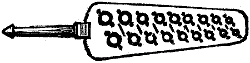
Fig. 292.
The first is the screw plate shown in Fig. 292. It consists of a hardened steel plate containing holes of varying diameters and threaded with screw threads of different pitches. These holes are provided with two diametrically opposite notches or slots so as to form cutting edges.
This tool is placed upon the end of the work and slowly rotated while under a hand pressure tending to force it upon the work, the teeth cutting grooves to form the thread and advancing along the bolt at a rate determined by the pitch of the thread.
The screw plate is suitable for the softer metals and upon diameters of 1⁄8 inch and less, in which the cutting duty is light; hence the holes do not so rapidly wear larger.
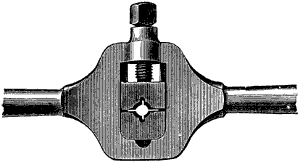
Fig. 293.
The second class consists of a stock and dies such as shown in Fig. 293. For each stock there are provided a set of dies having different diameters and pitches of thread.
In this class of tool the dies are opened out and placed upon the bolt. The set screw is tightened up, forcing the dies to their cut, and the stock is slowly rotated and a traverse taken down the work.
In some cases the dies are then again forced to the work by the set screw, and a cut taken by winding the stocks up the bolt, the operation being continued until the thread is fully developed and cut to the required diameter. In other cases the cut is carried down the bolt, only the dies being wound back to the top of the bolt after each cut is carried down. The difference between these two operations will be shown presently.
The thread in dies which take successive cuts to form a thread may be left full clear through the die, and will thus cut a full thread close up to the head collar or shoulder of the work. It is usual, however, to chamfer off the half threads at the ends of the dies, because if left of their full height they are apt to break off when in use. It is sometimes the practice, however, to chamfer off the first two threads on one side of the dies, leaving the teeth on the other side full, and to use the chamfered as the leading side in all cases in which the thread on the work does not require to be cut up to a shoulder, but turning the dies over with the full threaded teeth as the leading ones when the thread does require to be carried up to a head or shoulder on the work.
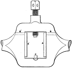
Fig. 294
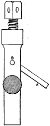
Fig. 295
To facilitate the insertion and extraction of the dies in and from their places in the stock, the Morse Twist Drill Co. employ the following construction. In Figs. 294 and 295 the pieces a, a′ which hold the dies are pivoted in the stock at b, so as to swing outward as in Fig. 295, and receive the dies which are slotted to fit them. These pieces are then swung into position in the stock. The lower die is provided with a hole to fit the pin c, hence when that die is placed home c acts as a detaining piece locking the pieces a, a′ through the medium of the bottom die.
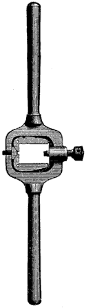
Fig. 296
In other dies of this class the two side pieces or levers which hold the dies are pivoted at the corner of the angle, as in Fig. 296. In the bottom of the stock is a sliding piece beveled at its top and meeting the bottom face of the levers; hence, by pressing this piece inwards the side pieces recede into a slot provided in the stock, and leave the opening free for the dies to pass into their places, when the pin is released and a spring brings the side pieces back. Now, since the bottom die rests upon the bottom angle of the side pieces the pressure of the set screw closes the side pieces to the dies holding them firmly.
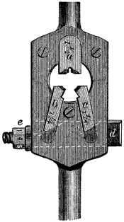
Fig. 297.
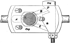
Fig. 298.
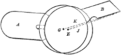
Fig. 299.
In Fig. 297 is shown Whitworth’s stocks and dies, the cap that holds the guide die a and the two chasers b, c in their seats or recesses in the stock being removed to expose the interior parts. The ends of the chasers b, c are beveled and abut against correspondingly beveled recesses in the key d, so that by operating the nut e on the end of the key the dies are caused to move longitudinally. The principles of action are more clearly shown in Fig. 298. The two cutting chasers b and c move in lines that would meet at d, and therefore at a point behind the centre or axis of the bolt being threaded; this has the effect of preserving their clearance. It is obvious, for example, that when these chasers cut a thread on the work it will move over toward guide a on account of the thread on the work sinking into the threads on a, and this motion would prevent the chasers b, c from cutting if they moved in a line pointing to the centre of the work. This is more clearly shown in Fig. 299, in which the guide die a and one of the cutting dies or chasers b is shown removed from the stock, while the bolt to be threaded is shown in two positions—one when the first cut is taken, and the other when the thread is finished. For the first cut the centre of the work is at e, for the last one it is at g, and this movement would, were the line of motion as denoted by the dotted lines, prevent the chaser from cutting, because, while the line of chaser motion would remain at j, pointing to the centre of work for the first cut, it would require a line at k to point to that centre for the last one; hence, when considered with relation to the work, the line of chaser motion has been moved forward, presenting the cutting edges at an angle that would prevent their cutting. By having their motion as shown in Fig. 299, however, the clearance of the chasers is preserved.
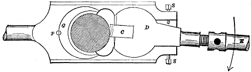
Fig. 300.
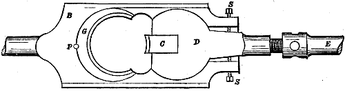
Fig. 301.
Referring now to the die a, it acts as a guide rather than as a cutting chaser, because it has virtually no clearance and cannot cut so freely as b and c; hence it offers a resistance to the moving of the bolt, or of the dies upon the bolt, in a lateral direction when the chaser teeth meet either a projection or a depression upon the work. The guide principle is, however, much more fully carried out in a design by Bodmer, which is shown in Fig. 300. Here there is but one cutting chaser c, the bush g being a guide let into a recess in the stock and secured thereon by a pin p. The chaser is set in a stock, d also let into a recess in the stock, and this recess, being circular, permits of stock d swinging. At s are two set-screws, which are employed to limit the amount of motion permitted to d. the handle e screws through d, and acts upon the edge of chaser c to put on the cut. The action of the tool is shown in Fig. 301, where it is shown upon a piece of work. Pulling the handle e causes d to swing in the stock, thus giving the chaser clearance, as shown. When the cut is carried down, a new cut may be put on by means of e, and on winding the stock in the opposite direction, d will swing in its seat, and cant or tilt the chaser in the opposite direction, giving it the necessary clearance to enable it to cut on the upward or back traverse. Another point of advantage is that the cutting edges are not rubbed by the work during the back stroke, and their sharpness is, therefore, greatly preserved. A die of this kind will produce work almost as true as the lathe, and, in the case of long, slender work, more true than the lathe; but it is obvious that, on account of the friction caused by the pressure of the work to the guide g, the tool will require more power to operate than the ordinary stock and die or the solid die.
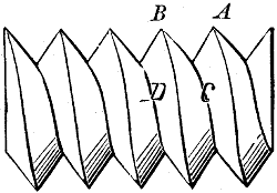
Fig. 302.
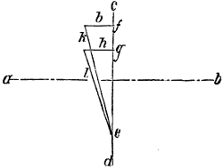
Fig. 303.
In adjustable dies which require to take more than one cut along the bolt to produce a fully developed thread, there is always a certain amount of friction between the sides of the thread in the die and the grooves being cut, because the angle of the thread at the top of a thread is less than the angle at the bottom. Thus in Fig. 302 the pitch at the top of thread (at a, b) is the same as at the bottom (c, d). Now suppose that in Fig. 303 a b represents the axial line of a bolt, and c d a line at a right angle to a b. The radius e f being equal to the circumference of the top of the thread, the pitch being represented by b; then k represents the angle of the top of the thread to the axial line a b. Now suppose that the radius e g represents the circumference at the bottom of the thread and to the pitch; then l is the angle of the bottom of the thread to the axial line of the work, and the difference in angle between k and l is the difference in angle between the top and bottom of the thread in the dies and the thread to be cut on the work.
Now the tops of the teeth on the die stand at the greatest angle l, in Fig. 303, when taking the first cut on the bolt, but the grooves they cut will be on the full diameter of the bolt, and will, therefore, stand at the angle k, hence the lengths of the teeth do not lie in the same planes as the grooves which they cut.
In cutting V-threads, however, the angle of the die threads gradually right themselves with the plane of the grooves attaining their nearest coincidence when closed to finish the thread.
Since, however, the full width of groove is in a square thread cut at the first cut taken by the dies, it is obvious that a square thread cannot be cut by this class of die, because the sides of the grooves would be cut away each time the dies were closed to take another cut.
Dies of this class require to have the threaded hole made of a larger diameter than is the diameter of the bolt they are intended to thread, the reason being as follows:—
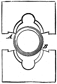
Fig. 304.
Suppose the threaded hole in the dies to be cut by a hob or master tap of the same diameter as the thread to be cut by the dies; when the dies are opened out and placed upon the work as in Fig. 304, the edges a, b will meet the work, and there will be nothing to steady the dies, which will, therefore, wobble and start a drunken thread, that is to say, a thread such as was shown in Fig. 253.
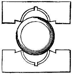
Fig. 305.
Instances have been known in the use of dies made in this manner, wherein the workman using a right-hand single-threaded pair of dies has cut a right or left-hand double or treble thread; the teeth of the dies acting as chasers well canted over, as shown in Fig. 305. It is necessary to this operation, however, that the diameter of the work be larger than the size of hob the dies were threaded with.

Fig. 306.
In Fig. 306 is shown a single right-hand and a treble left-hand thread cut by the author with the same pair of dies.
All that is necessary to perform this operation is to rotate the dies from left to right to produce a right-hand thread, and from right to left for a left-hand thread, exerting a pressure to cause the dies to advance more rapidly along the bolt than is due to the pitch of the thread. A double thread is produced when the dies traverse along the work twice as fast as is due to the pitch of the thread in the dies, and so on.
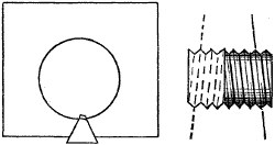
Fig. 307.
It is obvious, also, that a piece of a cylindrical thread may be used to cut a left-hand external thread. Thus in Fig. 307 is shown a square piece of metal having a notch cut in on one side of it and a piece of an external thread (as a tap inserted) in the notch. By forcing a piece of cylindrical work through the hole while rotating it, the piece of tap would cut upon the work a thread of the pitch of the tap, but a left-handed thread, which occurs because, as shown by the dotted lines of the figure, the thread on one side of a bolt slopes in opposite directions to its direction on the other, and in the above operation the thread on one side is taken to cut the thread on the other.
These methods of cutting left-hand threads with right-handed ones are mentioned simply as curiosities of thread cutting, and not as being of any practical value.
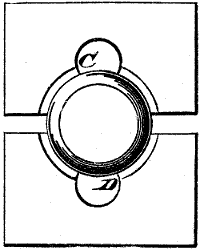
Fig. 308.
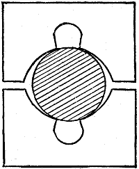
Fig. 309.
To proceed, then: to avoid these difficulties it is usual to thread the dies with a hob or master tap of a diameter equal to twice the depth of the thread, larger than the size of bolt the dies are to thread. In this case the dies fit to the bolt at the first cut, as shown in Fig. 308, c, d being the cutting edges. The relation of the circle of the thread in the dies to that of the work during the final cut is shown in Fig. 309.
There is yet another objection to tapping the dies with a hob of the diameter of the bolt to be threaded, in that the teeth fit perfectly to the thread of the bolt when the latter is threaded to the proper diameter, producing a great deal of friction, and being difficult to make cut, especially when the cutting edges have become slightly dulled from use.
Referring now to taking a cut up the bolt or work as well as down, it will be noted that supposing the dies to have a right-hand thread, and to be rotating from left to right, they will be passing down the bolt and the edges c, d (Fig. 308) will be the cutting ones. But when the dies are rotated from right to left to bring them to the end of the bolt again, c, d will be rubbed by the thread, which tends to abrade them and thus destroy their sharpness.
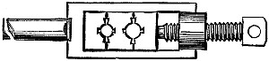
Fig. 310.
In some cases two or more pairs of dies are fitted to the same stock, as shown in Fig. 310, but this is objectionable, because it is always desirable to have the hole in the dies central to the length of the stock, so that when placed to the work the stock shall be balanced, which will render it easier to start the thread true with the axial line of the bolt.
From what has been said with reference to Fig. 303, it is obvious that a square thread cannot be cut by a die that opens and closes to take successive cuts along the work, but such threads may be cut upon work that is of sufficient strength to withstand the twisting pressure of the dies, by making a solid die, and tapering off the threads for some distance at the mouth of the die, so as to enable the die to take its bite or grip upon the work, and start itself. It is necessary, however, to give to the die as many flutes (and therefore cutting edges), as possible, or else to make flutes wide and the teeth as short as will leave them sufficiently strong, both these means serving to avoid friction.

Fig. 311.
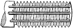
Fig. 312.
The teeth for adjustable dies, such as shown in Fig. 293, are cut as follows:—There is inserted between the two dies a piece of metal, separating them when set together to a distance equal to twice the depth of the thread, added to the distance the faces of the dies are to be apart when the dies are set to cut to this designated or proper diameter. The tapping hole is then drilled (with the pieces in place) to the diameter of the bolt the die is for. The form of hob used by the Morse Twist Drill & Machine Company, to cut the thread, is shown in Fig. 311. The unthreaded part at the entering end is made to a diameter equal to that of the work the dies are to be used in; the thread at the entering end is made sunk in one half the height of the full thread, and is flattened off one half the height of a full thread, so that the top of the thread is even with the diameter of the unthreaded part at the entering end. The thread then runs a straight taper up the hob until a distance equal to the diameter of the nut is reached, and the length of hob equal to its diameter is made a full and parallel thread for finishing the die teeth with. The thread on the taper part has more taper at the root of the thread than it has at the top of the same, and the diameter of the full and parallel part at the shank end of the thread is made of a diameter equal to twice the height or depth of a full thread, larger than the diameter at the entering end of the hob. The hob thus becomes a taper and relieved tap cutting a full thread at one passage through the dies. If the hob is made parallel and a full thread from end to end, as in Fig. 312, the dies must traverse up and down the hob, or the hob through the dies to form a full thread.
The third class of stock and die is intended to cut a full thread at one passage along the work, while at the same time provision is made, whereby, to take up the wear due to the abrasion of the cutting edges, which wear would cause the diameter of thread cut to be above the standard.
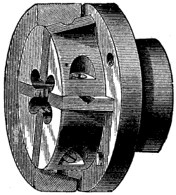
Fig. 313.
In Fig. 313 is shown the Grant adjustable die made by the Pratt & Whitney Company. It consists of four chasers or toothed cutting tools, inserted in radial recesses or slots in an iron disc or collet encircled by an iron ring. Each chaser is beveled at its end to fit a corresponding bevel in the ring, and is grooved on one of its side faces to receive the hardened point of a screw that is inserted in the collet to hold the chaser in its adjusted position. Four screws extend up through the central flange or body of the collet, two of which serve to draw down the ring, and by reason of the taper on the ring move the chasers equally towards the centre and reduce the cutting diameter of the die, while the other two hold the ring in the desired position, or force it upward to enlarge the cutting diameter of the die. The range of adjustment permitted by this arrangement is 1⁄32 inch. The dies may be taken out and ground up to sharpen.
The object of cutting grooves in the sides of the chasers is that the fine burrs formed by the ends of the set screws do not prevent the chasers from moving easily in the collet during the process of adjustment; the groove also acts as a shoulder for the screw end to press the chaser down to its seat. These chasers are marked to their respective places in the collet, and are so made that if one chaser should break, a new one can be supplied to fit to its place, the teeth of the new one falling exactly in line with the teeth on the other three, whereas under ordinary conditions if one chaser breaks, a full set of four new ones must be obtained.
In this die, as in all others which cut a full thread at one passage along the work, the front teeth of the chasers are beveled off as shown in the cut; this is necessary to enable the dies to take hold of or “bite” the work, the chamfer giving a relief to the cutting edge, while at the same time forming to a certain extent a wedge facilitating the entrance of the work into the die.
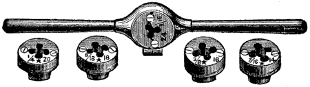
Fig. 314.
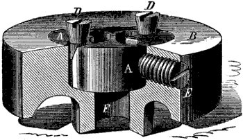
Fig. 315.
Fig. 314 represents J. J. Grant’s patent die, termed by its makers (Wiley and Russel) the “lightening die.” In this, as in other similar stocks, several collets with dies of various pitches and diameters of thread, fit to one stock. The nut of the stock is split on one side, and is provided with lugs on that side to receive a screw, which operates to open and enlarge the bore to release a collet, or close thereon and grip it, as may be required when inserting or extracting the same. The dies are formed as shown in Fig. 315, in which a, a are the dies, and b the collet. To open the dies within the collet, the screws e are loosened and the screws d are tightened, while to close the dies d, d are loosened and e are tightened; thus the adjustment to size is effected by these four screws, while the screws d also serve to hold the dies to the collet b. The collets are provided with a collar having a bore f, through which the work passes, so that the dies may be guided true when starting upon the work; but if it is required to cut a thread close up to a head or shoulder, the stock is turned upside down, not only to have the collet out of the way of the head or shoulder, but also because the thread of the dies on the collet side are chamfered off (as is necessary in all solid dies, or dies which cut a full thread at one traverse down the work) so as to enable them to grip or bite the work, and start the thread upon it as before stated.