Volume 2 — Chapter XXV.—VICE WORK.
Reading edition
Vice work may be said to include all those operations performed by the machinist that are not included in the work done by machine tools. In England vice work is divided into two distinct classes, viz., fitting and erecting. The fitter fits the work together after it has been operated upon by the lathe planer and other machine tools, and the erector receives the work from the fitter and erects it in place upon the engine or machine. Fitting requires more skill than turning, and erecting still more than fitting, but it is at the same time to be observed that the operations of the erector includes a great many of those of the fitter. In treating of the subjects of vice work and erecting, it appears to the author desirable to treat at the same time of some operations that are not usually included in those trades, because they are performed with tools similar to those used by the fitter, and may be treated equally as well in this way as in any other, while a knowledge of them cannot fail to be of great service to both the fitter and erector. Among the operations here referred to are some of the uses of the hammer; such, for example, as in straightening metal plates.
The vice used by the machinist varies both in construction and size according to the class of work it is to hold. For ordinary work the vice may possess the conveniences of swiveling and a quick return motion, but when heavy chipping constitutes a large proportion of the work to be done the legged vice is preferable.
The height of vice jaws from the floor is usually greater for very small work than for the ordinary work of the machine shop, because the work needs to be more clearly observed without compelling the operator to stoop to examine it. The gripping surfaces of vice jaws are usually made to meet a little the closest at the top, so as to grip the work close to the top and enable work cut off with a chisel to be cut clean and level with the jaws.
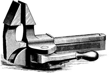
Fig. 2083.
The jaws of the wood-worker’s vice are made then as in Fig. 2083, and reach higher above the screw than the vices used for iron work, because the work is often of considerable depth, and being light will not lie still of its own weight, as is the case with iron.
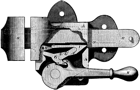
Fig. 2084.
An example of the ordinary vice of the machine shop is shown in Fig. 2084, which represents partly in section a patent swivel vice. a is the jaw in one piece with the body of the vice, and b is the movable jaw, being the one nearest to the operator. The movable jaw is allowed to slide freely through the fixed one (being pushed or pulled by hand), or is drawn upon and grips the work by operating the handle or lever h. The means of accomplishing this result are as follows: As shown in the cut, b is free to be moved in or out, but if h be pulled away from the vice, the shoulder c, meeting the shoulder n, will move the toggle g, and this, through the medium of g′, moves the tooth bar t, so as to engage with the teeth on the side of the movable jaw bar shown at t. As soon as the teeth t meet the teeth t the two travel together, and the jaw b closes on and grips the work. But as the motion is small in amount, the jaw b should be placed so to nearly or quite touch the work before h is operated. To unloose the work, the handle h is operated in an opposite direction, and the hook m meets m and pulls t to the position shown. The spring s operates upon a hook at u, to engage the teeth t, with the rack t, as soon as the handle h is moved in the tightening direction. The vice grips with great force, because during the tightening the toggle, g is nearly straight, and its movement less than would be the case with a screw-vice having the ordinary pitch of thread and under an equal amount of handle movement.
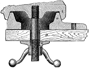
Fig. 2085.
In this vice the fixed jaw is made to fasten permanently to the work bench, but in others having a similar tightening mechanism the fixed jaw is so attached to the bench as to allow of being swivelled. The method of accomplishing this is shown in Fig. 2085, in which s is the foot of the vice bored conical to receive a cone on the casting r, which is fastened to the bench b. w is a washer and h the double arm nut. Loosening this nut permits of the vice being rotated upon r.
When handle h is operated to release the movable jaw it can be moved rapidly to open and receive the work, and to close upon the work, when by a second handle movement the work can be gripped, the operation being much quicker than when the movable jaw is traversed by a screw and nut.
In this vice the gripping surface of the jaws are always parallel one to the other, and attachments are employed to grip taper work as wedges.
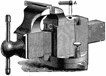
Fig. 2086.
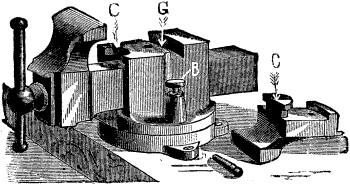
Fig. 2087.
In Fig. 2086 is represented a patent adjustable jaw vice, which is also shown in Fig. 2087 with the adjustable jaw removed and upside down. From the construction it is apparent that the groove g, being an arc of a circle of which c is the centre, the jaw is, as it were, pivoted horizontally, and can swing so as to let the plane of the jaw surfaces conform to the plane of the work; hence a wedge can be gripped all along the length enveloped by the jaws, and not at one corner or end only. When the pin a is inserted the jaw stands fixed parallel to the sliding jaw. The pin a engages in a ratchet in the base below it to secure the back vice jaw in position when it is set to any required angle.
A second convenience in this vice is that the whole vice can be swivelled upon the base that bolts to the bench, which is provided with a central hole and annular groove into which the base of the field jaw pivots; at b is a spring pin passing into holes in the bench plate, so that by lifting the pin b, the whole vice can be swung or rotated upon the base or bench plate, until the pin b falls into another hole in the base plate, which is provided with eight of these holes. The movable jaw is here operated by a screw and nut.
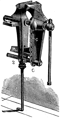
Fig. 2088.
Fig. 2088 represents a form of leg vice for heavy work. In the ordinary forms of this class of vice the two gripping surfaces of the jaws, only stand parallel and vertical when at one position, because the movable leg is pivoted at p; but in that shown in the figure the movable jaw is supported by the arm a, passing through the fixed leg l, which carries a nut n. A screw s, having journal bearing in the movable leg, screws through the nut n, and is connected to the upper screw by the chain c, which passes around a chain wheel provided on each screw, so that the movable leg moves in an upright position and the jaw faces stand parallel, no matter what the width of the work. This is a very substantial method of obtaining a desirable and important object, and greatly enhances the gripping capability of the vice. Fig. 2089 represents a sectional view of another patent vice. a is the sliding and b the fixed jaw. p is the bed plate carrying the steel rack plate h. Attached to each side of the base of the handle is a disk. These disks are carried on the outer end of the movable jaw a, and are held in place by the friction straps t, adjusted by the screws s. On the radial face of the disk is the pin k, which, when the handle or lever is lifted or raised, depresses the end of lever j, which at its other end raises the clutch g, disengaging the same from the rack h, as shown in the engraving. The jaw a is thus free to be moved by hand, so as to have contact with the work. To tighten the vice the handle is depressed, whereon k releases j and the latter permits the toothed clutch g to engage with the teeth of h. At the same time the bar d, which is pivoted to the disks, is drawn outward. The end of the bar d, meeting the surface of the lug shown on a, acts (in conjunction with the toothed clutch h) as a toggle fulcrum from which the disks may force the movable jaw to grip the work.
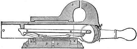
Fig. 2089.
This action may be more minutely described as follows: The end d of d is pivoted upon the disks, as shown; hence when the handle is depressed the effort of the end d is to move to the right, but d being fixed at the other end the pressure is exerted to force the movable jaw to the left, and therefore upon the work. The amount of jaw movement due to the depression of the handle is such that if that jaw is pushed near or close to the work the handle will stand about vertical downward when the vice firmly grips the work.
For vices whose jaws cannot be swiveled horizontally to enable them to conform to taper work, attachments for the jaws are sometimes provided, these attachments having the necessary swiveling feature. So likewise for gripping pipes, and similar purposes, attachments are made having circular recesses to receive the pipes.
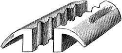
Fig. 2090.
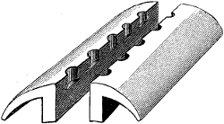
Fig. 2091.
To prevent the vice jaws from damaging the work surface, and also to hold some kinds of work more firmly, various forms of clamps, or coverings for the vice jaws are used. Thus Figs. 2090 and 2091 represent clamps for holding round or square pins. In the former the grooves pass entirely through the clamp jaws, so as to receive long pieces of wire, while in the latter the recesses are short, so as to form an abutment for the end of the pins, and act as a gauge in filing or cutting them off to length.
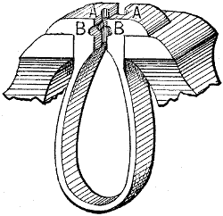
Fig. 2092.
An excellent form of pin clamp is shown in Fig. 2092, the spring bow at the bottom acting to hold the jaws open and force the faces against the vice jaws when the latter are opened. The flanges at b b rest upon the tops of the vice jaws; hence it will be seen that the clamp is not liable to fall off when the vice is opened to receive the work, which is placed either in the hole at a or that at b, as may be most desirable.
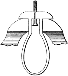
Fig. 2093.
Fig. 2093 shows such a clamp holding a screw, the clamp jaws being forced against the screw by the vice jaw pressure, when the vice jaws are opened the spring of the bow will cause the clamp jaws to open and release the screw.
Clamps such as shown in Figs. 2090 and 2091, but without the pin holes, are also provided, being made one pair of copper and another of lead, the latter being preferable for highly finished work. As the filings are apt to imbed in the copper, and, furthermore, as the copper gradually hardens upon its surface, the copper clamps require to be annealed occasionally, which may be done by heating them to a low red heat and dipping them in water. Lead clamps will hold small work very firmly, and are absolutely essential for triangular or other finished work having sharp corners, and also for highly finished cylindrical work, which may be held in them sufficiently firmly to be clipped without suffering damage from the vice jaws. A piece of thick leather, such as sole leather, also forms a very good clamp for finished work, but to prevent its falling off the vice jaws it is necessary to cut it nearly through on the outside and at the bent corner.
The hammer in some form or other is used in almost all kinds of mechanical manipulation, and in each of these applications it assumes a form varied to suit the nature of its duty, and of the material to be operated upon. In the machine shop it is used to drive, to stretch, and to straighten.
The most skilful of these operations are those involving stretching operations, as saw and plate straightening, examples of which will be given.
In using a hammer to drive, the weight and velocity of the hammer head are the main considerations. For example, the force of a blow delivered by a hammer weighing 1 lb., and travelling 40 feet in a second, will be equal to that weighing 2 lbs, and travelling 20 feet in a second; but the mechanical effects will be different. If received on the same area of impact the effects will sink deeper into the metal with the greater velocity, and they will extend to a less radius surrounding the area of impact. Thus in driving out a key that is fast in its seat, a quick blow is more effective than a slow one, both being assumed to have at the moment of impact an equal amount of mechanical force stored up in them. On the other hand, for riveting the reverse will be the case. In the stretching processes the hammer requires to fall with as dead a blow as possible. Thus the hammer handle is, for saw stretching, placed at such an angle to the length of the hammer that the latter stands about vertical when the blow is delivered. In straightening, the blow is varied to accommodate the nature of the work; thus a short crook or bend would be best straightened by a quick blow with a light hammer, and a long one by a slower blow with a heavier hammer, which would cause the effects of the blow to affect a greater radius around the part receiving the impact.
As an example of the difference in mechanical effect between a number of blows aggregating a given amount of energy and a single blow having an equal amount of energy, suppose the case of a key requiring a given amount of power to start it from its seat, and every blow delivered upon it with insufficient force to loosen its hold simply tends to swell and rivet it more firmly in the keyway.
Probably the most expert use of the hammer is required in the straightening of engravers’ plates, as bank-note plates; and next to this comes the ornamental repoussé work of the manufacturing jeweller.
The most expert hammer process of the machine shop is that of straightening rifle barrels and straightening saws and sheet metal plates.
In straightening rifle barrels, the operator is guided as to the straightness as follows: A black line is drawn across a piece of glass elevated to the light, and the straightener looks through the bore at this line, which throws a dark line of shadow along the rifle bore. If this line appears straight while the barrel is rotated the bore is straight; but if the line waves the barrel requires straightening, the judgment of the operator being relied upon to determine the amount of the error, its location, and the force and nature of the blow necessary to rectify it.
The following information on the duration of a blow is taken from Engineering, the results having been obtained from some experiments by Mr. Robert Sabine. These experiments, which were intended as preliminary to a more extended inquiry, were made with a view to find approximately how the duration of a blow varied with the weight of the hammer, its velocity of descent, and with the materials. An iron ball weighing 1⁄4 lb. was suspended by a fine wire from an insulated support upon the ceiling; so that when it hung vertically it just grazed the vertical face of an ordinary blacksmith’s anvil placed upon its side on a table. By raising the ball and letting it swing against the face of the anvil a blow of varying force could be struck. On rebounding, the ball was arrested whilst the excursion of the galvanometer needle was observed. By measuring the angle through which the ball was separated, its vertical fall and final velocity could be easily deduced. In this way the greatest vertical height from which the iron ball was let fall on to the face of the iron anvil was 4 ft., the least about 1⁄80 inch. Six readings were taken for each height, and they were invariably found to agree amongst each other. The averages only are given in the following records:
Vertical fall in inches. Duration of contact in seconds.
48 0.00008
36 0.00008
28 0.00008
17 0.00009
9 1⁄4 0.00010
4 0.00011
1 0.00013
0 1⁄4 0.00016
0 1⁄16 0.00018
0 1⁄32 0.00021
0 1⁄80 0.00030
From this it would appear that when the velocity of a blow is increased, the duration is decreased within a certain limit; but that it reaches a minimum. The velocity of impact in the first experiment was about sixty times as great as in the last one; but the duration of the blow appears to be reduced only to about one-fourth of the time. The blows given by two hammers of different weights were compared. No. 1 weighed 4 ozs., No. 2 weighed only 21⁄4 ozs. The durations of the blows were as follows:
Vertical fall. Duration of contact.
Ball No. 1. Ball No. 2.
inch. seconds. seconds.
1 0.000135 0.000098
4 0.000096 0.000083
It appears from this that a heavier hammer of the same material gives a longer duration of blow.
In the course of these experiments it was observed that the ball after striking the anvil rebounded irregularly, sometimes to a greater, at others to a less height, and that some relation appeared to exist between the heights to which the ball rebounded and the excursions of the galvanometer needle due to the residue of the charge.
In the next series, therefore, the rebounds of the iron ball from the iron anvil were measured and recorded, from which it appeared that when the rebound was greater the duration of contact was shorter, and vice versâ.
Vertical fall. Vertical rebound. Duration of blow.
inch. inch. seconds.
6 2 0.000120
6 2 1⁄2 0.000111
6 3 1⁄4 0.000101
6 3 1⁄2 0.000091
14 1⁄2 3 1⁄4 0.000106
14 1⁄2 4 1⁄2 0.000103
14 1⁄2 5 1⁄4 0.000095
14 1⁄2 6 1⁄2 0.000086
25 7 3⁄4 0.000096
25 8 1⁄4 0.000091
25 9 1⁄2 0.000086
25 12 0.000078
The explanation of this is probably that when the energy of the blow is expended in bruising or permanently altering the form of the hammer or anvil by which the contact of the two is prolonged, it has less energy left to enable it to rebound, and vice versâ. Substituting a brass anvil and brass ball, it was found that the blow was duller, the rebound much less, and the duration contact nearly three times as great as when the iron ball and anvil were used.
Vertical fall. Vertical rebound. Duration of contact.
inch. inch. seconds.
1 3⁄4 0 1⁄3 0.00036
6 1 0.00033
14 1⁄2 1 1⁄2 0.00026
25 2 0.00027
This series also shows the longer duration of the blow when its velocity is small. Using a brass anvil and iron ball the duration of the blow was greater than when both were of iron, but less than when both were of brass.
Vertical fall. Vertical rebound. Duration of contact.
inch. inch. seconds.
1 3⁄4 0 1⁄8 0.00021
6 0 1⁄2 0.00018
14 1⁄2 1 1⁄3 0.00015
25 2 0.00014
Striking the brass anvil with a common hammer, the duration of the blow appeared shorter when struck sharply.
Duration of contact.
seconds.
Moderate blow 0.00027
Harder blow 0.00019
Striking the blacksmith’s anvil with a common carpenter’s hammer, the duration appeared to be nearly constant.
Duration of contact.
seconds.
Moderate blow 0.00011
Harder blow 0.00010
It was, of course, necessary to allow in each case the hammer to rebound freely, and not to prevent it doing so by continuing to exert any pressure at the instant of the blow. When this condition was observed, it was invariably found that the harder and sharper the blow the shorter was its duration. It was also noticed that whenever the anvil gave out a sharp ringing sound, the duration of the blow was much shorter than when the sound was dull.
A very slight error would be introduced by reason of thermo-currents set up between the metals at the moment of the blow. By reversing the direction of charge of the accumulator, however, the effect from this cause was found to be quite inappreciable.
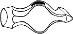
Fig. 2094.
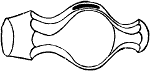
Fig. 2095.
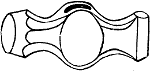
Fig. 2096.
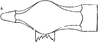
Fig. 2097.
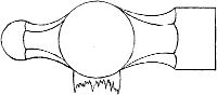
Fig. 2098.
The machinists’ hand hammer is usually made in one of the three forms shown in Figs. 2094, 2095 and 2096, and varies in weight from about 13⁄4 lbs. for heavy chipping to about 1⁄2 lb. for light work, the handle being about 15 inches long for the heavy, and about 10 or 12 for the light business. The round face is usually somewhat convex on its surface with its edge slightly rounded or beveled. The pane or pene a, Fig. 2097, is usually made in European practice to stand at a right angle to the axis of the handle as shown, while in the United States it is usually made to stand parallel with the handle as in Fig. 2096. The face end is sometimes given taper as in Figs. 2094 and 2095, and at others parallel as in Figs. 2097 and 2098, or nearly so. The pene is mostly used for riveting purposes, and it is obvious that with the pene at a right angle to the handle axis as in Fig. 2097, it will not matter whether the pene meets the work quite fair or not, especially as the pene is made slightly curved in its length, and it is easier to hold the hammer level sideways than it is to hold it so true lengthways that the pene, when forward, as in Fig. 2096, will meet the work fair.
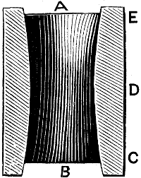
Fig. 2099.
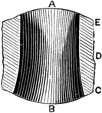
Fig. 2100.
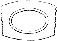
Fig. 2101.
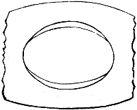
Fig. 2102.
The proper shape for the eye of a hammer is that shown in Figs. 2099 and 2100, a representing the top of the hammer. The two sides of the eye are rounded out from the centre towards each end, while the ends of the eye are made parallel. The form of the eye as viewed from the top a is as shown in Fig. 2102, while Fig. 2101 represents a view from the bottom b. The handle is fitted a driving fit and is driven in from side b, and is shaped as in Figs. 2103 and 2104 which are side and edge views.
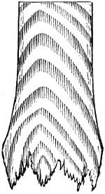
Fig. 2103.
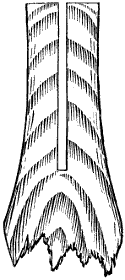
Fig. 2104.
From c to d the handle fills the eye, but from d to e it fills the eye lengthways only of the oval. A saw-slot, to receive a wedge, is cut in the handle, as shown in Fig. 2104. The wedge is best made of soft wood, which will compress and conform itself to the shape of the slot. To drive the handle into the eye, preparatory to wedging it permanently, it should be placed in the eye held vertically, with the tool head hanging downward, and the upper end struck with a mallet or hammer, which is better than resting the tool head on a block. The wedge should be made longer than will fill the slot, so that its upper end may project well, and the protruding part, which may split or bulge in the driving, may be cut off after the wedge is driven home.
The wedge should be driven first with a mallet and finally with a hammer. After every few blows on the wedge, the tool should be suspended by the handle and the end of the latter struck to keep the handle firmly home in the eye. This is necessary, because driving the wedge in is apt to drive the handle partly out of the eye.
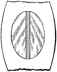
Fig. 2105.
The width of the wedge should equal the full length of the oval at the top of the eye, so that one wedge will spread the handle out to completely fill the eye, as shown in Fig. 2105. Metal wedges are not so good as wooden ones, because they have less elasticity and do not so readily conform to the shape of the saw-slot, for which reasons they are more apt to get loose. The taper on the wedge should be regulated to suit the amount of taper in the eye, while the thickness of the wedge should be sufficiently in excess of the width of the saw-cut, added to the taper in the eye, that there will be no danger of the end of the wedge meeting the bottom of the saw-slot.
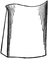
Fig. 2106.
By this method, the tool handle is locked to the tool eye by being spread at each end of the same. If the top end of the tool eye were rounded out both ways of the oval, two wedges would be required to spread the handle end to fit the eye, one wedge standing at a right angle to the other. In this case, one wedge may be of wood and one of metal, the one standing across the width of the oval usually being the metal one. The thin edge of the metal wedge is by some twisted, as shown by Fig. 2106, which causes the wedge to become somewhat locked when driven in.
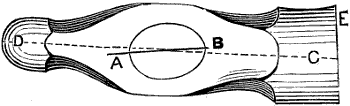
Fig. 2107.
In fitting the handle, care must be taken that its oval is made to stand true with the oval of the tool eye. Especially is this necessary in the case of a hammer. Suppose, for example, that in Fig. 2107 the length of the oval of the handle lies in the plane a b, while that of the eye lies in the plane c d, then the face of the hammer will meet the work on one side, and the hammer will wear on one side, as shown in figure at e. If, however, the eye is not true in the hammer, the handle must be fitted true to the body of the hammer; that is to say, to the line c d. The reason for this is that the hand naturally grasps the handle in such a manner that the length of the oval of the handle lies in the plane of the line of motion when striking a blow, and it is obvious that to strike a fair blow the length of the hammer should also stand in the plane of motion.
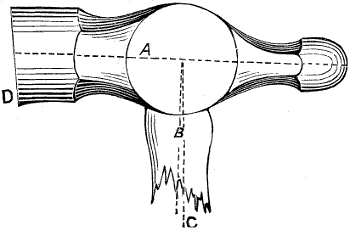
Fig. 2108.
The handle should also stand at a right angle to the plane of the length of the hammer head, viewed from the side elevation, as shown in Fig. 2108, in which the dotted line is the plane of the hammer’s length, while b represents a line at a right angle to a, and should, therefore, represent the axial line of the hammer handle. But suppose the handle stood as denoted by the dotted line c, then the face of the hammer would wear to one side, as shown in the figure at d.
In the operation of straightening iron or steel plates by hammer blows, the process when correctly carried out is one of liberating the strains (whose existence throws the plate out of a true plane) by stretching those parts that are unduly contracted. Every hammer blow should, therefore, be directed towards this end, for one misdirected blow entails the delivery of many others to correct its evil influence; hence, if several of such misdirected blows are given, the plate will have upon it a great many more hammer marks, or “hammer sinks” or chops, as they are sometimes termed, than are necessary. As a result, not only will the painter (in fine work) be given extra trouble in stopping the hollows to make a smooth surface, but the following evil will result: Every blow struck by the hammer compresses and proportionately stiffens the small surface upon which it is delivered, and creates a local tension upon the surrounding metal. The misdirected blows then cause a tension acting in opposition to the effect of the properly delivered ones; and though the whole plate may be stiffened by the gross amount of blows, yet there will be created local tensions in various parts of the plate, rendering it very likely to spring or buckle out of truth again. If, for example, we take a plate of iron and hammer it indiscriminately all over its surface, we shall find it very difficult to straighten it afterwards, not only on account of the foregoing reasons, but for the additional and most important one that the effect of the straightening blows will be less, on account of the hammered surface of the plate offering increased resistance to the effects of each blow; and after the plate is straightened, there will exist in it conflicting strains, an equilibrium of which holds the plate straight, but the weakening of any of which will cause the preponderance of the others to throw the plate out of straight; for the effects of the blows cannot be permanent unless the whole body of the iron is acted upon to an equal extent by the hammer. Suppose, for example, that we take a flat plate, and deliver upon it a series of blows round about its centre. The effect will be to make it hollow on one side and rounding on the other, the effect of the blows being, not only to indent the plate in the spots where they fell, but to carry the whole body of the middle out of true; because, the area of the iron being increased by the stretching effect of the blows, the centre leaves the straight line to accommodate the increased area. Thus, if we mark off a circle of, say, a foot in diameter, in the middle of a plate, and hammer it so as to stretch it and increase its area 1⁄8 inch each way, the form of the plate must alter to suit this added area, and the form of a dish or curve is the only one it can assume.
The skilful workman, so soon as he has ascertained where the plate is out of true, sets to work to stretch it, so as to draw the crooked place straight, taking care that the shape and weight of the hammer and the weight of the blows delivered shall bear a proper relation to the thickness of the plate and the material of which it is composed. If it is of consequence that the finished work shall bear no marks of the hammering (as in the case of engravers’ plates), an almost flat-faced hammer is employed; but for other work the shapes, as well as the weights, of the hammers vary.
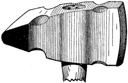
Fig. 2109.
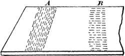
Fig. 2110.
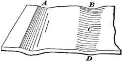
Fig. 2111.
Fig. 2109 represents what is called the long cross-face hammer, used in saw straightening for the first part of the process which is called the smithing. The face that is parallel to the handle is called the long one, and the other is the cross-face. These faces are at a right angle one to the other, so that without changing his position the operator may strike blows that will be lengthways in one direction, as at a, in Fig. 2110, and by turning the other face towards the work he may strike a second series standing as at b. Now, suppose we had a straight plate and delivered these two series of blows upon it, and it will bend to the shape shown in Fig. 2111, there being a straight wave at a, and another across the plate at b, but rounded in its length, so that the plate will be highest in the middle, or at c; if we turn the plate over and repeat the blows against the same places, it will become flat again. Both faces of this hammer are made alike, being rounded across the width and slightly rounded in the length, the amount of this rounding in either direction being important, because if the hammer leaves indentations, or what are technically called “chops,” they will appear after the saw has been ground up, even though the marks themselves are ground out, because in the grinding the hard skin of the plate is removed, and it goes back to a certain, but minute, extent towards its original shape. This it will do more in the spaces between the hammer blows than it will where the blows actually fell, giving the surface a slightly waved appearance.
The amount of roundness across the face regulates the widths, and the amount of roundness in the face length regulates the length of the hammer marks under any given force of blow. As the thicker the plate the more forcible the blow, therefore the larger the dimensions of the hammer mark.
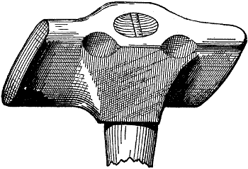
Fig. 2112.
The twist hammer, shown in Fig. 2112, is used for precisely the same purposes as the long cross-face, but on long and heavy saws or plates, and for the following reasons, namely: When the operator is engaged in straightening a short saw he can stand close to the spot he is hammering, and the arm using the hammer may be well bent at the elbow, which enables him to see the work plainly, and does not interfere with the use of the hammer, while the shape of the smithing hammer enables him to bend his elbow and still deliver the blows lengthways, in the required direction. But when a long and heavy plate is to be straightened, the end not on the anvil must be supported with the left hand, and it stands so far away from the anvil that he could not bend his elbow and still reach the anvil. With the twist hammer, however, he can reach his arm out straight forward to the anvil, to reach the work there, while still holding up the other end, which he could not do if his elbow were bent. By turning the twist hammer over he can vary the direction of the blow the same as with the long cross-face.
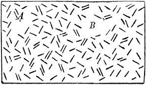
Fig. 2113.
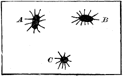
Fig. 2114.
It is obvious that by slightly bending the elbow and turning either of these hammers over the blows may be caused to be in any required direction, as shown in Fig. 2113. These two hammers are used for the straightening or smithing processes, and not to regulate the tension, because the effects of their blows do not extend equally around the part struck, but follow the form of the hammer marks, whose shapes are shown in Fig. 2114, at a and b, the radiating lines denoting the directions in which the effects extend; obviously the size of these marks depends upon the shape of the hammer face and the force of the blow.
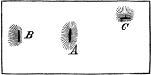
Fig. 2115.
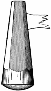
Fig. 2116.
An inspection of hammered saw plates, however, will show that the marks (which are scarcely visible, having a merely dulled surface), are usually about one-half wider than the thickness of the plate, and about four or five times as long as they are wide. Obviously, also, the direction of the effects of a blow follow the direction in which the hammer travels. If, for example, the long cross-face falls vertically its effects will extend equally all around the hammer mark, as at a in Fig. 2115, but if the hammer moved laterally to the left while falling its blows would have more effect on the left-hand side of the mark as at b, or if it moved away from the operator its effects would extend most in front as at c, the amount increasing with the force of the blow, and it may be remarked that quick blows are not used, because they would produce indentations or chops; hence, the force of the blow is regulated by the weight of the hammer rather than by the velocity it travels at. On account of the oval shape of the blow delivered by the long cross-face and by the twist hammers, the dog-head hammer, shown in Fig. 2116, is used to regulate the tension of the plate or saw, the effects of its blow when delivered vertically being circular, as at a, in Fig. 2117; obviously, however, if in falling it moved vertically in the direction of arrow c the effects would extend as at b. But while the dog-head is used entirely for regulating the tension, it may also be used for the same purposes as either the long cross-face or the twist hammer, because the smith operates to equalize the tension at the same time that he is taking down the lumps; hence he changes from one hammer to the other in an instant, and if after regulating the tension with the dog-head he should happen to require to do some smithing, before regulating the tension in another, he would go right on with the dog-head and do the intermediate smithing without changing to the smithing hammer. Or, in some cases, he may use the long cross-face to produce a similar effect to that of the dog-head, by letting the blows cross each other, thus distributing the hammer’s effects more equally than if the blows all lay in one direction.
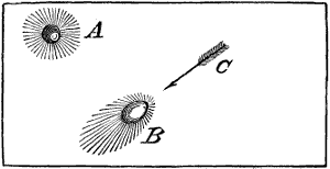
Fig. 2117.
In circular saws, which usually run at high velocity, there is generated a centrifugal force that is sufficient to actually stretch the saw and make it of larger diameter. As the outer edge of the saw runs at a greater velocity than the eye it stretches most, and therefore the equality of tension throughout the saw is destroyed, the outer surface becoming loose and causing the saw to wabble as it revolves, or to run to one side if one side of the timber happens to be harder than the other, as in the case of meeting the edge of a knot.
The amount of looseness obviously depends upon the amount the saw expands from the centrifugal force, and this clearly depends upon the speed the saw is to run at; so the saw straightener requires to know at what speed the saw is to run, and, knowing this, he gives it more tension at the outside than at the eye; or, in other words, while the eye is the loosest, the tension gradually increases towards the circumference, the amount of increase being such that when the saw is running the centrifugal force, and consequent stretching of the saw, will equalize the tension and cause the saw to run steadily.
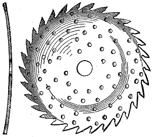
Fig. 2118.
If the eye of a circular saw is loose, or, in other words, if it is rim bound when running, it will dish, as in Fig. 2118, and the rounded side rubbing against the side of the saw slot or kerf, will cause the saw to become heated and the eye to expand more than the outer edges, thus increasing the dish. But if the saw strikes a knot on the hollow side it may throw the dish over to the other side of the saw in an instant. The remedy is to hammer the saw with the dog-head as shown in the figure, not touching the eye, and letting the blows fall closer together towards the circumference.
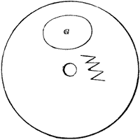
Fig. 2119.
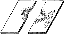
Fig. 2120.
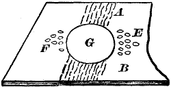
Fig. 2121.
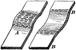
Fig. 2122.
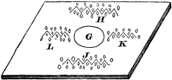
Fig. 2123.
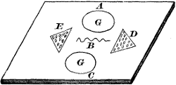
Fig. 2124.
On the other hand, if the eye is tight and the circumference loose the saw will flop from side to side as it runs, and the remedy is to stretch it round about the eye, letting the blows fall wider apart as the outer edge of the saw is approached. The combinations of tight and loose places may be so numerous in circular saws that as the smith proceeds in testing with the straight-edge he marks them, drawing a circular mark, as at g, in Fig. 2119, to denote loose, and the zig-zag marks to indicate tight places. To cite some practical examples of the principles here laid down, suppose we have in Fig. 2120 a plate with a kink or bend in the edge, and as this would stiffen the plate there, it would be called a tight place. To take this out, the hammer marks would be delivered on one side, radiating from the top of the convexity, as on the left, and on the other as shown radiating from the other end of the concavity, as on the right, the smithing hammer being used. This would induce a tight place at a which would be removed by dog-head blows delivered on both sides of the plate. Suppose we had a plate with a loose place, as at g in Fig. 2121. We may take it out by long cross-face blows, as at a and b, delivered on both sides of the plate, or we might run the dog-head on both sides of the plate, both at a and at b, the effect being in either case to stretch out the metal on both sides of the loose place g, and pull it out. In doing this, however, we shall have caused tight places at e and f, which we remove with dog-head blows, as shown. If a plate had a simple bend in it, as in Fig. 2122, hammer blows would first be delivered on one side, as at a, and on the other side, as at b. A much more complicated case would be a loose place at g, in Fig. 2123, with tight places at h, j, k, and l, for which the hammer blows would be delivered as marked, and on both sides of the plate. Another complicated case is given in Fig. 2124, g g being two loose places, with tight places between them and on each side. In this case, the hammering with the long cross-face would induce tight places at d and e, requiring hammer blows as denoted by the marks.
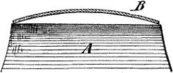
Fig. 2125.
The saw or plate straightener’s anvil or block is about 12 by 18 inches on its face, which must be very smooth and is slightly convex, because it is necessary that the plate should be solid on the block, directly beneath the part of its surface which is being hammered, otherwise the effect of the blows will be entirely altered. If, for instance, a, in Fig. 2125, represents the straightening block, and b a plate resting thereon, then the blows struck upon the plate anywhere save over the very edges of the anvil will have but little effect, because of the spring and rebound of the plate; and the effect of the blow will be distributed over a large area of the metal, tending to spring it rather than give it a permanent set. If the blow is a quick one, it may indeed indent the plate without having any straightening effect. On the other hand, by stretching the skin on the upper side of the plate, it will actually, under a succession of blows, become more bent. In fact, to use a straightening block, so large in proportion to the size of the plate that the latter cannot be adjusted so that the part of the plate struck lies solid on the block, renders all the principles above explained almost valueless, and is a process of pounding, in a promiscuous way, productive of hammer marks, and altogether fatal to the production of true work.
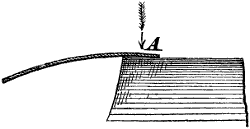
Fig. 2126.
To straighten the plate shown in Fig. 2125, we place it upon the anvil, as shown in Fig. 2126, striking blows as denoted at a, and placing but a very small portion of the plate over the anvil at first; and as it is straightened, we pass it gradually farther over the anvil, taking care that it is not, at any part of the process, placed so far over the anvil as to drum, which will always take place if the part of the plate struck does not bed, under the force of the blow, well upon the anvil.
VOL. II. THE HAMMER AND ITS USES. PLATE VIII.
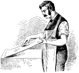
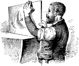
Fig. 2127. Fig. 2128.
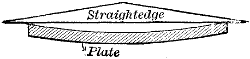
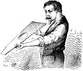
Fig. 2129.

Fig. 2130. Fig. 2131.
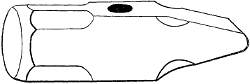
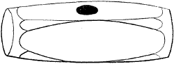
Fig. 2132. Fig. 2133.
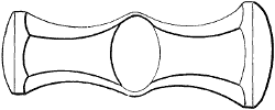
Fig. 2134.
The methods employed to discover in what parts a plate requires stretching, in order to straighten it and to equalize its tension, are as follow: Suppose we have a plate, say 18 inches by 24, and having a thickness of 19 gauge, and we rest one end of it upon the block and support the other end in the left hand, as shown in Fig. 2127; then with the right hand we exert a sudden pressure in the middle of the plate; and quickly releasing this pressure, we watch where its bending movement takes place. If it occurs most at the outer edges, it proves that the plate is contracted in the middle; while, if the centre of the plate moves the most, it demonstrates that it is expanded in the middle. And the same rule applies to any part of the plate. This way of testing may be implicitly relied upon for all plates or sheets thin enough to be sprung by hand pressure.
Another plan, applicable for either thick or thin plates, and used conjointly with the first named, is to stand the plate on edge with the light in front, as in Fig. 2128; we then cast one eye along the face of the plate upon which the light falls, and any unevenness will be made plainly visible by the shadows upon the surface of the plate. The eye should also be cast along the edges to note any twist or locate any kinks.
We may take a thin piece of plate in the hands, and if it is loose in the middle and we lay a straight-edge upon its upper surface, and try to bend the middle of the plate downward with the fingers, it will go down under the finger pressure, the straight-edge showing a hollow place in the middle; and the same thing will occur if the straight-edge be tried with either side of the plate uppermost. But if the piece be tight in the middle and we test with the fingers and straight-edge in the same way, the middle instead of bending downwards, appears to rise up, the straight-edge showing it to be rounded. In the first case the middle moves because it is loose, and in the second the edges move because they are loose.
Fig. 2129 represents a plate for a circular saw that is loose in the middle, and if we bend the middle down it will become concave on the top, as shown in the figure. But if it were tight in the middle and loose at the outer edge, it would become, under the same pressure, convex on the top, as in Fig. 2130, and here again the part that is loose moves the most.
In thin saws, such as hand saws, the workman takes the saw in his hands, as in Fig. 2131, and bends it up and down so that by close observation he may see where it moves the most, and then discover the loose places, or he may watch for the tight places, since these are the places he must attack.
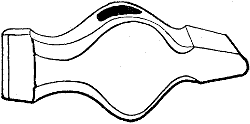
Fig. 2135.
The sledge hammer used by the machinist is usually made in one of the two forms shown in Figs. 2132 and 2133, the latter being the most serviceable because it has two faces which may be used for driving purposes, which is the only use the machinist has for the sledge hammer. The coppersmith varies the shape of his hammer faces to suit the nature of the work, thus Fig. 2134 represents a coppersmith’s hammer, its two faces being of different sizes and of different curvature, and both being used to form convex surfaces having different degrees of curvature, it being noted that the curvature of the hammer face is always less than that of the work. In other forms of coppersmith’s hammers there are two penes and no face, one being at a right angle to the other, as in Fig. 2135, the penes being rounded as in the figure, or sometimes square.
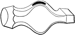
Fig. 2136.
Fig. 2136 represents a coppersmith’s hammer with a square nosed pene, which is sometimes made to stand at a right angle to the handle as in the figure, and at others parallel to it.
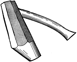
Fig. 2137.
Fig. 2137 represents the file cutter’s hammer, whose handle is at the angle shown because the chisel is held at an angle, the point or cutting edge being nearest to the workman; hence if the handle were at a right angle to the hammer length his arm would require to be considerably elevated in order to let the hammer face fall fair on the chisel head, whereas by setting the handle at the angle shown the arm need not be elevated, and the blow may be given by a movement of the wrist.
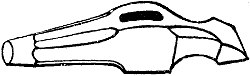
Fig. 2138.
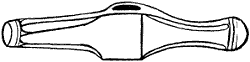
Fig. 2139.
Figs. 2138 and 2139 represent hammers used by boiler-makers for riveting boiler seams. The faces are made small so that if the blows are properly directed the edge of the face will not meet the boiler plate and indent it. These hammers are made long and narrow so that the weight may lie in the same direction as the hammer travels in when delivering the blow, and thus cause the effects of the hammer blows to penetrate deeper than if the hammer was wider.
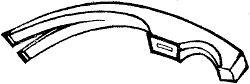
Fig. 2140.
In the cooper’s hammer, shown in Fig. 2140, the face extends flush up to the head, thus enabling it to strike a hoop upon a barrel without danger of the extreme end or top of the hammer meeting the barrel, and preventing the hammer face from meeting the edge of the barrel hoop when driving it on the barrel. The face is square and its front edge therefore a straight line, which is necessary on account of the circular shape of the hoop of the barrel.
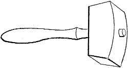
Fig. 2141.
The mallet is made in various forms to suit the nature of the work and the tools it is to be used upon. Thus the carpenter’s mallet is a rectangular block, such as shown in Fig. 2141. It is composed of wood, because the carpenter’s tools are held in wooden handles, and a metal hammer would split them in course of time. It is rectangular in shape so that it may be applied to tools held in a corner of the work, where a round mallet could not, if of sufficient diameter, give the necessary weight. For such carpenters’ or wood-workers’ tools as are for heavy duty, and the tools for which have ferrules at the head of their handles to prevent them from splitting, the mallet is made cylindrical or round, as it is termed, and has an iron band at each end to prevent the face from spreading or splitting.
The stonemason’s mallet is also of wood, and is disk-shaped, with the handle in the centre, the circumferential surface forming the face. The reason for this is that his tools are of steel and have no handles; hence if the blow continually fell on the same part or spot of the mallet face it would sink or indent holes in it, which is prevented by utilising the whole circumference of the mallet for the face.
An excellent mallet for the machinist’s use, for driving finished work without damaging it, is formed of raw hide secured in a metal eye that receives the handle. Or for the same purpose a lead hammer is used, being especially serviceable for setting work in machines.
What is known as pening, or paning, consists of hammering the skin of metal to stretch it on the side that is hammered. It may be employed either to bend or to straighten. Suppose, for example, we have a piece of metal that is bent to a half circle, and if we take a light hammer and hammer it on the concave side and all over its surface the piece will straighten out to an amount depending on the amount of pening. Or if he hammers the convex side the piece will bend to a smaller circle. The principle involved is, that if one side of a piece is elongated and the other remains of its original length, the only shape it can assume to accommodate or permit the elongation is that of a curve of which the convex side is the longest. It follows, therefore, that the hammer blows must in pening be sufficiently light to condense or stretch the metal on one side only of the metal, and not forcible enough to effect it all through.
In order to accomplish this stretching as rapidly as possible it is necessary to use a light hammer, with sufficient force to be expended in condensing the metal at its surface, and to so form the hammer that it shall expend its force upon the work with a dead blow, that is, with as little rebound as possible. These results are best accomplished with a ball pened hammer, such as shown in Fig. 2108 and weighing about 1⁄2 lb. The blows should fall dead; that is, the hammer should fall, to a great extent, by its own weight, the number rather than the force of the blows being depended upon; hence, the hammer marks will not be deep. This is of especial importance when pening has to be performed upon finished work, because, if the marks sink deeply, proportionately more grinding or filing is required to efface them; and for this reason the force of the blows should be as near equal as possible. Another and a more important reason, however, is that the effect of the pening does not penetrate deeply; and if much of the pened surface is removed, the effects of the pening will be also removed. The work should not be rested upon metal, but upon wood.
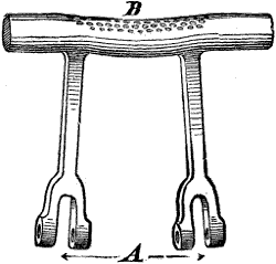
Fig. 2142.
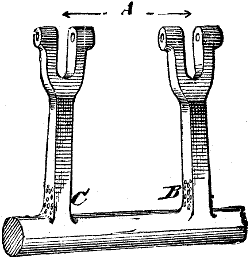
Fig. 2143.
The following are examples of pening. Fig. 2142 represents a shaft bent as shown, the arms being too wide at a, which may be corrected by pening at b. If the error was in the arms themselves and not in the stem, the side faces of the arms would require to be pened. Thus in Fig. 2143 the distance a is too short, and the pening must be at b c.
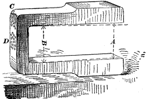
Fig. 2144.
Fig. 2144 represents a strap requiring to be closed across a, the pening being at c or d. But as pening at d would bend the crown and unpair the bed of the brasses, it is preferable to pene at c. In either case the jaws will close as denoted by the dotted lines.
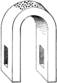
Fig. 2145.
Fig. 2145 represents another common form of connecting rod strap, and in this case the pening may be most quickly and effectively done at the crown as denoted by the dots; and as this would alter the inside curve, the brass or box fitting into it must be refitted. In case the pening should be overdone it is better to modify it by filing away some of the pened surface.
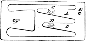
Fig. 2146.
Cast iron is more rapidly affected by pening than either wrought iron or steel. One of the most useful applications of pening is in the case of moulding patterns, which in time may become warped from the rapping of the pattern in the mould, and this warping may be corrected by judicious pening, or suppose that a number of plates, such as represented in Fig. 2146, having been cast, it is found that the ends of the tongues a b curl up when cooling in the mould, then the tongues may be pened as at c d, throwing them down to the requisite amount, and thus moulding the pattern to accommodate the curling in cooling.
The riveting usually performed by the machinist is generally upon cold metal. The blows in this case should fall dead and the riveting be performed with a view to stretching the metal uniformly and evenly over the surface to be riveted.
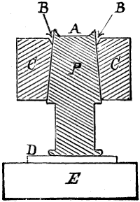
Fig. 2147.
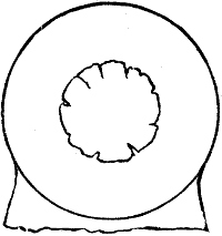
Fig. 2148.
An excellent example of cold riveting is given in the crank pin p in Figs. 2147 and 2148. c is the crank (both being shown in section). The end of the pin should be recessed as shown at a, so that it may be the more readily riveted outward to fill the countersink shown in the crank at b, b. The crank-pin is rested upon a piece of copper d interposed between it and the iron block e to prevent damage to the finished face of the crank-pin.
The riveting blows should be given with a ball-faced hammer, and delivered with a view to stretch the whole end face of the crank-pin evenly. Otherwise the riveted surface will be apt to split as shown. This usually occurs from not riveting the area at and near the circumference sufficiently, although it may occur from riveting that part of the area too much. The line of travel of the hammer should not be directly vertical, but somewhat lateral in a direction from the centre towards the circumference. If the countersink is a deep one, it is desirable to leave the crank-pin sufficiently too long, so that after the riveting has proceeded some time the surface of the metal which has become condensed and crystallized from the direct impact of the hammer blows, may be chipped away, leaving a surface that is swollen by the riveting without being so much condensed. This enables a much greater spreading of the metal without splitting it.
If in this class of work the riveted piece (as the crank-pin) is not driven in very tight before riveting, the riveting blows will be apt to jar the pin back. Hence, it is necessary to occasionally drive the pin home. The riveting should proceed equally all over, as if one side be riveted in advance of the other it tends to throw the pin out of true. When, however, the riveting begins to bed the pin, four equidistant places may be riveted home in advance so as to bring the pin home and hold it firmly.
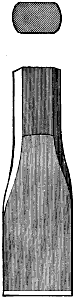
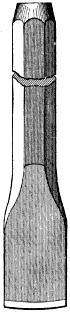

Fig. 2149. Fig. 2150. Fig. 2151.
The Chisel.—The machinist’s cold chisel is made from the two forms of steel shown in Figs. 2149, 2150, and 2151, and of these the former is preferable because it has two broad flats diametrally opposite and these form a guide to the eye in holding the chisel on the grindstone, and aid in grinding the facets that form the cutting edge true. Furthermore, as the cutting edge is in the same plane as these flats they serve as a guide to denote when the chisel edge lies parallel to the work surface, which is necessary to produce true and smooth chipping.
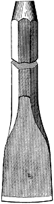

Fig. 2152. Fig. 2153.
The width of the chisel may be made greater, as in Figs. 2152 and 2153, for brass or cast-iron work than for wrought iron or steel for the following reasons. On account of the toughness and hardness of wrought iron and steel the full force of a 13⁄4 lb. hammer, having a handle 13 inches long, may be used on a chisel about 7⁄8 inch wide without danger of causing the metal to break out below the chipping line, but if such a chisel be used with full force blows upon cast iron or brass the metal is apt to break out in front of the chisel, the line of fracture often passing below the level it is intended to chip down to. Hence if a narrow chisel is used lighter blows must be delivered. But by using a broader chisel the force of the blow is distributed over a longer length of cutting edge, and full force blows may be used without danger of breaking out the metal.
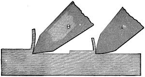
Fig. 2154.
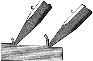
Fig. 2155.
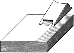
Fig. 2156.
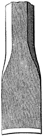
Fig. 2157.
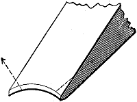
Fig. 2158.
The cutting end of the chisel should be kept thin, as in that case it cuts both easier and smoother. The total length of a chisel should not when new exceed 8 inches, for if made longer it is not suitable for heavy or smooth chipping, as it will bend and spring under heavy blows, and cannot be held steadily. The forged part should not exceed about 21⁄2 or 3 inches in length, as a long taper greatly conduces to springiness, whereas solidity is of great importance both to rapid and smooth work. The facets forming the cutting edge should be straight in their widths, as at b in Fig. 2154, and not rounded as at a, so that the face next to the work may form a guide in holding the chisel at the proper angle to maintain the depth of the cut. This angle depends upon the nature of the material to be cut; the facets forming an angle one to the other of about 65° for cast steel and about 50° for gun metal or brass. The more acute these angles the nearer the body of the chisel lies parallel with the work and the more effective the hammer blows. Thus in Fig. 2155 chisel c is the position of the chisel for wrought iron, and position d is for steel. The angles should always be made, therefore, as acute as the hardness of the material will permit. If they are too acute the cutting edge will be apt to bend in its length, while if not sufficiently acute they will not cut keen enough; hence the object is to make them as acute as possible without causing the cutting edge to bend in its length. For copper and other soft metals the angle may be about 30° or 35°, the chisel end being kept thin so that it may not become wedged between the work and the chipping, which will bend but little, and is, therefore, apt to grip the wedge end of the chisel. The cutting edge should be slightly rounded in its length, which will strengthen it and also enable a fine finishing clip to be taken off, as in Fig. 2156, the width of the chip not extending fully across the chisel width so that the corners are not under duty and are not, therefore, liable to break, or dig in and prevent smooth chipping. In some practice the edge is made straight in its length, as shown in Fig. 2149, which is permissible in heavy chipping when a cape chisel has been used, but in any event an edge rounded in its length is preferable. If the edge is hollow in its length, as shown in Fig. 2157, and magnified in Fig. 2158, the chip acts as a wedge to force the corners outwards as denoted by the arrows, causing them to break under a heavy cut, and, furthermore, a smooth cut cannot be taken when the corners of the chisel meet the work surface.
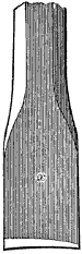
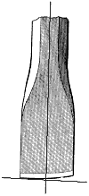
Fig. 2159. Fig. 2160.
If the facets are ground under on one side, those on the other, as in Fig. 2159, the edge will not be parallel with the flats of the chisel, so that in holding it the flats will not form a guide to determine when the edge lies parallel to the work surface as it should do. The edge should also be at a right angle to the length of chisel, as denoted by the lines, as in Fig. 2160, for if not at a right angle the chisel will be apt to move sideways after each blow, and cannot be held steadily.
The chisel should be held as close to its head as possible, so that the hand will steady the head as much as possible, and should be pushed forward firmly and steadily to its cut, which will greatly facilitate rapid and smooth chipping, and for wrought iron and copper it is found better to occasionally moisten the chisel with oil or water, the former being preferable.

Fig. 2161.
Messrs Tangye, of Birmingham, have introduced the employment of chisel holders, such as shown in Fig. 2161, the object being to fit to each holder a number of short pieces of steel for chisels so that a number can be ground or forged at one time; obviously chisels of different shapes require different forms of handle.
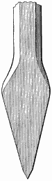


Fig. 2162. Fig. 2163. Fig. 2164.
When a heavy cut is to be taken the cape (Fig. 2162) chisel is used, first to carry through grooves or channels, such as shown in Fig. 2176 at a, b, and c, the distance apart of these grooves being slightly less than the width of the flat chisel, whose cut is shown partly carried across at d in the figure. The width of a cape chisel should gradually decrease from a to b in Fig. 2163, so that its side will be free in the groove it cuts, and the chisel head will be free to be moved sideways, and the direction of the groove may be governed thereby. If the chisel end be made parallel, as at c in Fig. 2164, it will have no play in the groove and the head cannot be moved; hence if the groove is started out of line, as it is apt to be, it will continue so.
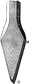

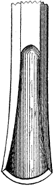
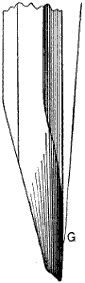
Fig. 2165. Fig. 2166. Fig. 2167. Fig. 2168.
The round-nosed chisel, Figs. 2165 and 2166, may be straight from h nearly to the point g, but should be bevelled at and near g, so that the chisel head may be raised or lowered to govern the depth of the cut. Its round nose should also be wider than the metal higher up, so that the chisel head may be moved sideways to govern the direction of the cut as in the cape chisel. The cow mouth chisel, Figs. 2167 and 2168, should be bevelled from g to the point to enable the governing of the depth of the cut, and should be of greater curvature than the corner it is to cut out, so that its corners cannot wedge in the work.
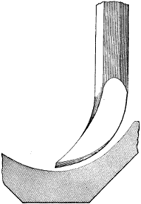
Fig. 2169.
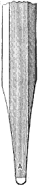
Fig. 2170.
The oil groove chisel, Figs. 2169 and 2170, should be wider at the cutting edge than at a for reasons already stated, and of less curvature than the bore of the brass or bearing it is to cut the oil groove in.

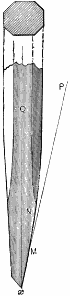


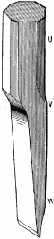
Fig. 2171. Fig. 2172. Fig. 2173. Fig. 2174. Fig. 2175.
The diamond point chisel, Figs. 2171 and 2172, may be made in two ways. First, as in Figs. 2173 and 2174, for shallow holes, and as in Figs. 2171 and 2172 for deep ones. In shallow holes the chisel can be leaned over, as in Fig. 2176 at y, whereas in deep ones it must be held straight so that the chisel body may not meet the other side of the hole, slot, or keyway. The form shown in Fig. 2172 is the strongest, because its point is brought into line with the body of the steel, as shown by the line q. The side chisel, Fig. 2175, for cutting out the sides of keyways or slots, should be bevelled from w to the cutting edge for the reasons already given, and straight from w to v, the line v w projecting slightly above or beyond the body u. An application of the cow mouth chisel is shown at l, and one of the side chisel is shown at z in Fig. 2176. All these chisels are tempered to a blue color.
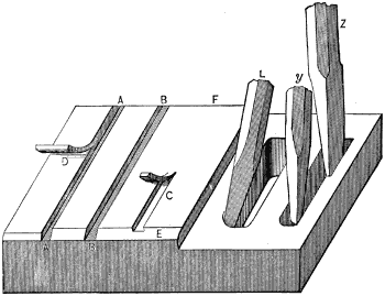
Fig. 2176.
The chisel that is driven by hammer blows may be said to be to some extent a connecting link between the hammer and the cutting tool, the main difference being that the chisel moves to the work, while the work generally moves to the cutting tool. In many stone-dressing tools the chisel and hammer are combined, inasmuch as that the end of the hammer is chisel shaped; an example of this kind of tool being given in the pick that flour millers use to dress their grinding stones. On the other hand we may show the connection between the chisel and the cutting tool by the fact that the wood-worker uses the chisel by driving it with a mallet, and also by using it for a cutting tool for work driven in the lathe. Indeed, we may take one of these carpenter’s chisels and fasten it to the revolving shaft of a wood-planing machine, and it becomes a planing knife; or we may put it into a carpenter’s hand plane, and by pushing it to the work it becomes a plane blade. In each case it is simply a wedge whose end is made more or less acute so as to make it as sharp as possible, while still retaining strength enough to sever the material it is to operate upon.
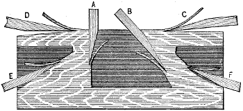
Fig. 2177.
In whatever form we may apply this wedge, there are certain well-defined mechanical principles that govern its use. Thus when we employ it as a hand tool its direction of motion, under hammer blows, is governed by the inclination of the face which meets the strongest side of the work, while it is the weakest side of the material that moves the most to admit the wedge and therefore becomes the chip, cutting, or shaving. In Fig. 2177, for example, we have the carpenter’s chisel operating at a and b to cut out a recess or mortise, and it is seen that so long as the face of the chisel that is next to the work is placed level with the straight surface of the work the depth of cut will be equal; or in other words, the line of motion of the chisel is that of the chisel face that lies against the work. At c and d is a chisel with, in the one instance, the straight, and in the other the bevelled face toward the work surface. In both cases the cut would gradually deepen because the lower surface of the chisel is not parallel to the face of the work.
If now we consider the extreme cutting edge of chisel or wedge-shaped tools it will readily occur that but for the metal behind this fine edge the shaving or cutting would come off in a straight ribbon, and that the bend or curl that the cutting assumes increases with the angle of the face of the wedge that meets the cutting, shaving, or chip.
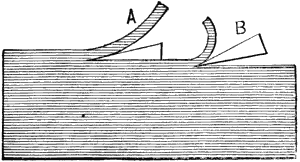
Fig. 2178.
I may, for example, take a piece of lead, and with a penknife held as at a, Fig. 2178, cut off a curl bent to a large curve, but if I hold the same knife as at b it will cause the shaving to curl up more. Now it has taken some power to effect this extra bending or curling, and it is therefore desirable to avoid it as far as possible. For the purpose of distinction we may call that face of the chisel which meets the shaving the top face, and that which lies next to the main body of the work the bottom face. Now at whatever angle either face of the chisel may be to the other, and in whatever way we present the chisel to the work, the strength of the cutting edge depends upon the angle of the bottom face to the line of motion of the chisel, and this is a principle that applies to all tools embodying the wedge principle, whether they are moved by a machine or by hand.
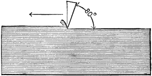
Fig. 2179.
Thus, in Fig. 2179 we have placed the bottom face at an angle of 80° to the line of tool motion, which is denoted by the arrow, and we at once perceive its weakness. If the angle of the top face to the line of tool motion is determined upon, we may therefore obtain the strongest cutting edge in a hand-moved tool by causing the bottom angle to lie flat upon the work surface.
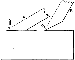
Fig. 2180.
But in tools driven by power, and therefore accurately guided in their line of motion, it is preferable to let the bottom face clear the work surface, save at the extreme cutting edge. The front face of the wedge or tool is that which mainly determines its keenness, as may be seen from Fig. 2180, in which we have the wedge or tool differently placed with relation to the work, that in position a obviously being the keenest and less liable to break from the strain of the cutting process.
If we now turn our attention to that class of chisel or wedge-shaped tools in which the cutting edge is not a straight line, but may be stepped or curved—as, for example, the carpenter’s plane blade—we shall find that so long as the blade stands at a right angle to the surface it is operating upon, as in Fig. 2183 at b, the shape of surface it cuts will exactly correspond to the shape of its cutting edge; but so soon as the tool is inclined to its line of motion its cutting edge will, if curved, produce a different degree of curvature on the work.
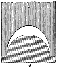
Fig. 2181.
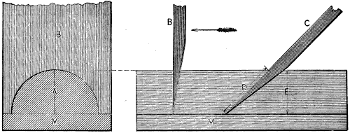
Fig. 2182. Fig. 2183.
Suppose, for instance, that we have in the figure a piece of moulding m and a plane blade b, and the length of the cutting edge is denoted by a, Fig. 2182; now suppose that the blade is inclined to its line of motion (as in the case of carpenters’ planes) and stands at c, Fig. 2183: we then find that the cutting edge must extend to the length or depth d, and it is plain that the depth of the curve on the moulding is less than the depth of the cutting edge that produces it; the radius e being less than of d, so that if we place the cutter c upright on the moulding it will appear as shown in Fig. 2181. If, therefore, we are required to make a blade that will produce a given depth of moulding when moved in a straight line and presented at a given angle to the work, we must find out what shape the blade must be to produce the given shape of moulding, which we may do as follows:
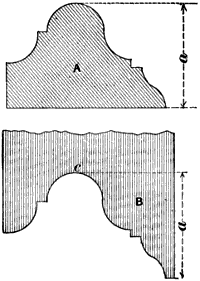
Fig. 2184.
In Fig. 2184 let a be a section of the moulding, and if the blade or knife is to stand perpendicular, as shown at b, Fig. 2183, and if it is moved in a straight line in the direction of the length of the work, then its shape would necessarily be that shown at b, Fig. 2184, or merely the reverse of a. In the position mentioned it could be used only as a sweep applicable to some few uses, but not adapted to cutting. To become a cutting tool it must be inclined and stand at some angle of less than 90° to its line of motion.
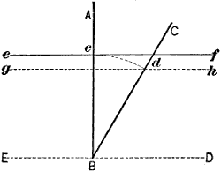
Fig. 2185.
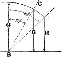
Fig. 2186.
Thus in Fig. 2185 d b e represents the bottom of the moulding and line of motion of the cutter, and a b the cutter perpendicular to it, the highest point of the cutting edge, as c of Fig. 2184, being at c, Fig. 2185. The height or thickness of the moulding cut would be the space between the lines e b d and e c f, but the cutter assuming the position b c at an angle of 30° from a b, the point c is brought to d; consequently the highest line of the moulding would now be g d h, and its thickness less. This is further exhibited in Fig. 2186, where a represents the original depth section of Fig. 2184 that would be formed by knife b of Fig. 2184 when standing perpendicular; and g shows the depth with the same knife when placed as b c, Fig. 2185, or at 30° inclination, and h shows the depth that would be cut with the same knife or cutter at 45°. It is now evident that every change in the inclination of the same cutter would effect a change in the shape of moulding which it cuts, and to produce a given style of moulding the shape of the cutter must be decided by its inclination, or the angle at which it is used.
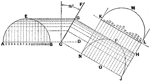
Fig. 2187.
The method of projecting a given section of moulding in order to exhibit the form that the curve of the opening should assume on the face of the knife, is shown in Fig. 2187. Upon a horizontal line a b c d draw a section of the required style of moulding, as shown at a e b. To the right of this draw a line, as f c, to meet the base line a b c d, and as f c represents the cutter, it must stand at the same angle that the proposed cutter is to have—in this particular example 30° from the perpendicular. From the highest point of the section a e b draw a horizontal line e g, meeting f c in g. From points g and c draw lines, as c j and g h, of any convenient length, at right angles to f c. At any distance from g h draw k l parallel to g h, and upon k l trace the section of moulding a e b, as k m l. Draw lines from the extreme edges k and l of k m l, as k n, l j, perpendicular to k l, cutting g h and meeting c j at n and j. e g being parallel to a b c d, g will be the point on the cutter where the top e of the moulding will come on the highest point of the cutting edge, and c g will be the entire length of cutting edge or height of opening measured on the face of the cutter f c. c j being drawn from the lowest point c of the cutter and g h being drawn from g, the highest cutting point, both lines at right angles to g c, then their distance from each other, as p o, must obviously represent the extreme height of opening in the cutter in its new position or front view, and k l, representing the width of moulding transferred to n j by the parallel lines k n and l j, will show the width of opening in the cutter. Having now the height and width, it only remains to project an indefinite number of points and trace the curve through them. Divide a b into a number of parts, and to avoid confusion mark the points of division thus obtained upon a b—1, 2, 3, 4, &c. Divide k l in an exactly similar manner and into the same number of parts, and mark the divisions i., ii., iii., iv., &c. Erect perpendiculars from points 1, 2, 3, 4, &c., meeting the curve a e b, and from the points thus found on a e b draw horizontal lines to f c; from the termini of these horizontals on f c draw the remaining lines parallel to and between g h and c j. From the divisions i., ii., iii., iv., &c., on k l, let drop the perpendiculars, cutting the other series of lines at right angles. A point of the curve will then be at the intersection of the line from 1 on a b, with line i on k l; another at the intersection of the line originating at 2 with that from ii, and so on, and the proper curve is found by tracing from n through the intersections to p, and from p to j. Then k n being one side of the cutter and l j the other, n p j is the curve that the opening or cutting edges must have to cut the profile a e b, with the cutter set at f c, or 30°.
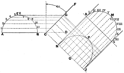
Fig. 2188.
The same method is shown in Fig. 2188, except that in this case, instead of dividing a b and k l, the divisions are made directly on the peripheries a 6 b and k vi. l by stepping round with the dividers. The cutter f c is shown in this case at an angle of 45°, in order that the change in form which the curve assumes with the cutter at different angles may be clearly seen by comparing the curve n p j of Fig. 2187 with the same in Fig. 2188. The two figures are similar in other respects, and as the lettering is the same on each, the description of Fig. 2187 will apply equally to Fig. 2188.
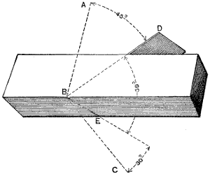
Fig. 2189.
There remains one more case of cutters moving in right lines, and that is where, besides having an inclination backward, as at f c, Fig. 2187, making a vertical angle to the line of motion, they are placed at an angle across the guiding piece also, or “skewing,” thus making an angle to the line of motion on a horizontal plane as well as on a vertical one. Thus, suppose an ordinary carpenter’s plane to have the cutter or “iron” turned partly round and placed so that the cutting edge, instead of lying at a right angle across the body, crosses it at some other angle. Fig. 2189 represents an ordinary carpenter’s plane with the blade so placed. Here the edge, or rather side, d b, of the blade inclines back at an angle, as a b d, which is 45° in this case, to the perpendicular line a b on the side of the plane. For convenience call a b d the vertical angle. The lower or cutting edge e b of the blade also crosses the bottom of the plane at an angle e b c—30° in this instance—to a line b c, crossing the bottom at right angles. Now, it is evident that this latter angle e b c will influence the form of the cutter, if, instead of being a flat plane, as represented for clearness in Fig. 2189, it had a cutting edge of curved outline for cutting mouldings or similar work. But in either case the angle that d b or one side of the blade makes to e b, or the cutting edge—that is, the angle d b e—must be found in order to cut off the blank for the cutter or knife at the right “slant.”
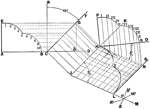
Fig. 2190.
The method given in Figs. 2187 and 2188 of determining the form of cutter to produce a moulding of given profile now undergoes a modification where there are two angles to be taken into consideration instead of one. As an example, suppose a cutter is required that is to be fixed in such a position in its carrier or block that the handle a b d, or “vertical angle,” of Fig. 2189 is, say, 45°, and the angle e b c, or “horizontal angle,” of Fig. 2189 shall be 30°. Required the angle at which the bottom of the blank for the cutter must be cut off; or the angle that the side d b and lower edge b e of Fig. 2189 would make to each other, measured on the face of the cutter, and required the outline of cutting edge to be traced on the face of cutter to cut the section of moulding a e b, Fig. 2190: draw a horizontal line, as a b c d, and erect a perpendicular, as c r. From c draw c f, making an angle to c r equal to the “vertical angle,” or angle a b d, Fig. 2189, which is 45° in this case. Draw a profile of the required moulding, as a e b, with its back a b coincident to the horizontal line a b c d. Draw a horizontal line from the highest point of the profile, as e, to meet f c in g. Draw parallel lines c j and g h, from c and g respectively, of any convenient length and making right angles to f c. At right angles to g h and c j, and parallel to f c, draw k h j to represent one side or edge of the cutter, but the angle of the lower end or angle d b e of Fig. 2189 must now be determined; to do this, draw an indefinite horizontal line, a b c, Fig. 2191, and from any point, as b, drop a perpendicular b d; now, from b set off on a b c the distance c b of Fig. 2190, obtaining point e, and from e extend a perpendicular above and below a b c, as f e h. From e on e f set off distance g b of Fig. 2190, obtaining j on e f. From b draw a line, making the same angle to b d that the angle e b c is in Fig. 2189, or 30° in this case, and cutting e h in k. Set off distance e k from e on a c, obtaining l; draw l j. Now, on Fig. 2190, with centre at h, and radius l j of Fig. 2191, describe arc w x, and from j as centre, on Fig. 2190, and b k of Fig. 2191 as radius, describe arc y z. Through the intersection v of arcs y z and w x, j l m must be drawn, making the proper angle to the side j h k of the cutter; this angle is 69° in this case, as found by construction. From h draw h n parallel to j l, and from h draw h o at the same angle to h n that b k is to b d, Fig. 2191, or angle e b c, Fig. 2189. Place a duplicate of a e b, with its base coincident to h o and corner a at h, as h p r. From r draw r n at right angles to h r and cutting h n at n; through n draw s n l parallel to k h j. Then while k h j represents one edge of the cutter, s n l will be the other, and j l the cutting edge before the opening is cut out. Divide the curves e b and p r similarly, obtaining points 1, 2, 3, &c., and i., ii., iii., &c., respectively. From points 1, 2, 3, &c., lines are to be drawn parallel to e g, meeting g c, continued from g c parallel to g h, and meeting h j, and from h j parallel to h n, meeting n l. From points i., ii., iii., &c., lines are to be drawn perpendicular to h r, meeting h n and continued from h n, parallel to h j, to j l, thus intersecting the first series. Lines from points 1, 2, 3, &c., then determine the height of different points of the curve, and those from i., ii., iii., &c., their location laterally; hence, by tracing through the intersections of 1 with i., 2 with ii., &c., the curve h t l is obtained. The two outside lines k h j and s n l may now represent the edges of a piece of steel of which the cutter is to be made, and h t l will be the contour of cutting edge that must be given it in order that when, fixed for use at the angles named, it will form the required moulding a e b.
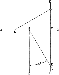
Fig. 2191.
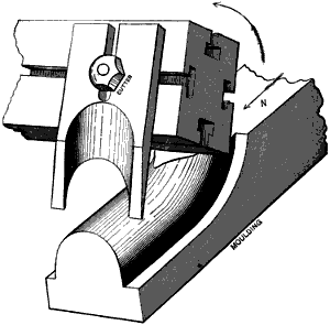
Fig. 2192.
If the chisel, knife, or cutter revolves in a circle, instead of in a right or straight line, the problem is again different, and the shape of cutting edge necessary to produce a given shape of moulding is again altered. Let Fig. 2192, for example, represent the bar or head of a wood moulding machine, the bar or head revolving in the direction of the arrow, and the moulding being moved beneath it in a straight line endways as denoted by the arrow at n.
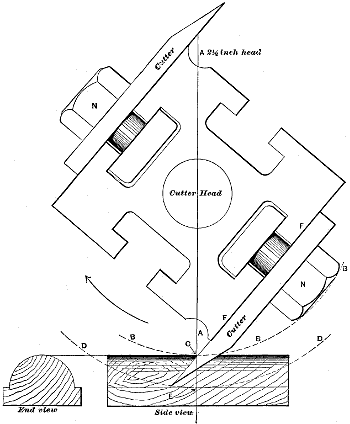
Fig. 2193.
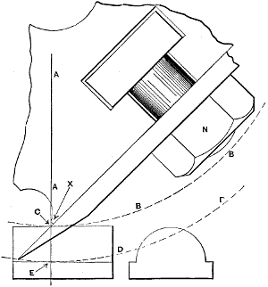
Fig. 2194.
In order that the nut that holds the cutter to the head may clear the top of the moulding the highest cutting point of the cutter must not come nearer to the corner of the head than 1⁄4 inch. This is shown in the end view of a 21⁄2 inch cutter head in Fig. 2193, the circle b representing the path of revolution of the nut. In larger heads the nut will clear better.
Now we may consider that the cutter simply revolves about a circle whose diameter is the largest that can be described on the end of the square bar that drives it.
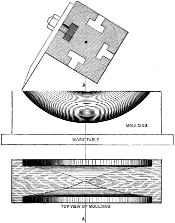
Fig. 2195.
If, for instance, we look at the end of the bar as it is presented in Fig. 2195, we see that the circle just fills the square, and that if we cut off all four corners, leaving the bar round, as denoted by the circle, the chisel will revolve in the same path as before. Now suppose we place beneath the revolving chisel a piece of square timber, and raise this timber while holding it horizontally, as would be done by raising the work table. It will cut the work to the shape shown in the two views in the figure, enabling us to observe the important point that the only part of the work that the chisel has cut to its finished shape is that which lies on the line a a. This line passes through the axis on which the bar and cutter revolve, and represents the line of motion of the work in feeding upward to the chisel.
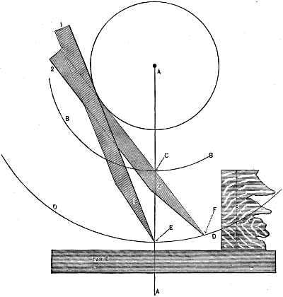
Fig. 2196.
If now we were to move the work endways upon the table, we should simply cause the moulding to be finished to shape as it passes the line a; because all the cutting is done before and up to the time that the chisel edge reaches this line; or in other words, each part of the chisel edge begins to cut as soon as it meets the moulding, and ceases to cut as soon as it reaches this line. We may now draw this circle and put on it a chisel in two positions, one at the time its lowest cutting point is crossing the line a and the other at the time the highest point on its cutting edge is passing the line, these positions being marked 1 and 2 in Fig. 2196; the depth of moulding to be cut being shown at s. Now, since the chisel revolves on the centre of the circle, the path of motion on its highest cutting point c will be as shown by the circle b, and that of the lowest point or end e of its cutting edge will be that of the circle d, while the depth of moulding it will cut is the distance between c and e, measured along the line a a, this depth corresponding to depth shown at s.
Clearly when the chisel has arrived at position 2, the moulding will be finished to shape, and it is therefore plain that it takes a length of cutter-edge from c to f to cut a moulding whose depth is s, or what is the same thing, c e.
But to solve the question in this way, we require for every different depth of moulding to make such a sketch, and the square bar that drives the chisel is made in various sizes, each different size again altering the length or depth of chisel edge necessary for a given depth of moulding.
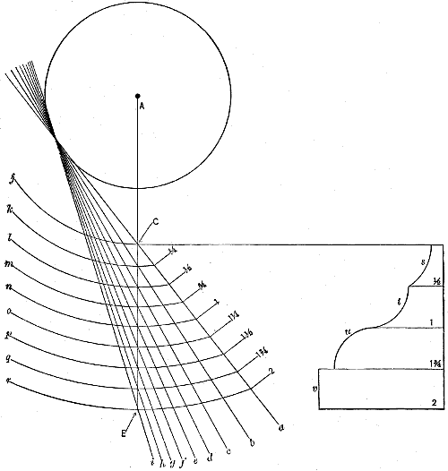
Fig. 2197.
But we may carry the solution forward to the greatest simplicity for each size of square bar, and for any depth of moulding that can be dressed on that size of bar, by the following means:—In Fig. 2197 we have the circle and the line a as before; the depth from c to e being the greatest depth of moulding to which the square bar is intended to drive the chisels; while point c is the nearest point to the square bar at which the top of the moulding must be placed. Line a represents a chisel cutting at its highest point; line b a chisel cutting the moulding to final shape at 1⁄4 inch below c, on the line a; line c a chisel cutting the moulding to final shape at a distance of 1⁄2 inch below point c and measured on the line a; lines d, e, f, g, h, and i represent similar chisel positions, the last meeting the point e, which is the lowest point at which the chisel will cut. Suppose, now, we set a pair of compasses one point at the centre a of the circle, and strike the arc j; this arc will represent the path of motion of that part of the chisel edge that would finish the moulding to shape at c; similarly arc k represents the path of motion of that part of the chisel edge that cuts the moulding to final shape on the line a, and at a distance of 1⁄4 inch below c, and so on until we come to arc r, which represents the path of motion of the end of the chisel. All these arcs are carried to meet the first chisel position c a, and from these points of intersection with this line c a we mark lines representing those on a common measuring rule. The first of these from c we mark 1⁄4, the next 1⁄2, the next 3⁄4, and so on to 2, these denoting the measurement or depth of chisel necessary to cut the corresponding depth of moulding. If, for example, we are asked to set a pair of compasses to the depth of cutting edge necessary to cut a moulding that is an inch deep, all we do is to set one leg of the compasses at c, and the other at line 1 on the line c a; or if the moulding is to be 2 inches deep, we set the compasses from c to 2 on line c a. We have here, in fact, constructed a graduated scale that is destined to be found among the tools of every workman who forms moulding cutters, and if we examine it we shall find that the line that is marked 1⁄4 inch from c is not 1⁄4 inch but about 5⁄16 inch; its distance from c being the depth of chisel edge necessary to cut a moulding that is 1⁄4 inch deep.