Volume 2 — Chapter XXXV.—WOOD WORKING MACHINERY. (continued 2)
Reading edition
q, is a fast and q′, q′′, are loose pulleys, one driven by an open belt r, Fig. 3150, and the other by a crossed belt r′, from a countershaft. The belt-shifting forks are operated by lever s, whose upper end engages with the rod t, which is operated by the lever u.
The loose pulleys q′ and q′′ are twice as wide as the fast pulley q.
Now suppose that lever u is moved to the right, and the belt would be moved from the loose pulley q′′ to the fast pulley q, while the other belt would merely be moved or shifted from one to the other side of loose pulley q′.
Similarly if lever u, be moved to the left, the belt on the loose pulley q′ will be moved on to the fast pulley q, and the belt on pulley q′′ would simply be moved across the face of the pulley, and as the countershaft pulleys for the two pulleys are of different diameters, therefore two rates of motion are obtained.
The shaft v, on which pulley q is fast, drives the pinion l, which drives m, the latter gearing with the rack beneath the carriage.
The carriage is guided by the wheels z, which are secured to it, and run on the iron guideways z′, the flanges of the wheels preventing side play, and causing the carriage traverse to be in a straight line.
WOOD-PLANING MACHINES.
The simplest form of planing machine for wood work, is the hand planer or buzz planer, as it is termed, an example of this class of machine being shown in Fig. 3152, which has been designed and constructed by George Richards, for the use of pattern-makers.
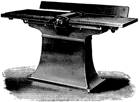
Fig. 3152.
It consists of a frame carrying a revolving shaft, which is by some called the cutter head, and by others the cutter bar, and to which the cutters or knives are attached.
The work is rested upon the work table, or else pressed against a guide or fence, and fed by hand over the revolving knives, whose cutting edges protrude above the surface of the table, to the amount of the depth of cut it is intended to take.
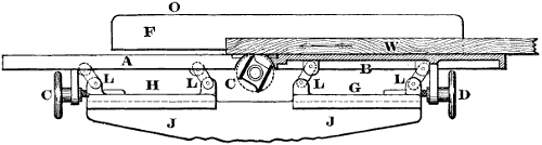
Fig. 3153.
In this example, however, the table is made in two sections, the front one of which is below the cutter edges to an amount equal to the depth of the cut, and the back one level with the cutter edge, when the latter is at its highest point in its path of revolution, the construction being shown in Fig. 3153, in which j, j, represents the top part of the main frame of the machine, c the cutter head, b the front or feed table, a the back or delivery table, and w a piece of work being fed in the direction of the arrow.
Upon the upper surface of the frame j, j, and on the feed side of the cutter head is the carriage g, to which are pivoted two links l, l, which support the feed table b. At d is a hand wheel whose screw has journal bearing in a lug from the table, while the screw threads into a nut provided in the carriage. Obviously then by operating the hand wheel d, carriage g is moved along the top of the frame j, and the height of table b is adjusted. Thus if the carriage g is traversed to the left, the link l would fall more nearly to a horizontal position, and table b would lower. Or if g were moved to the right, links l would stand more nearly vertical, and table b would be raised, it being understood that table b is not permitted to move endways. Similarly by means of hand wheel c, carriage h may be moved to adjust the height of table a.
By this construction, the work can bed fairly on the delivery side, as well as on the feeding side of the cutter head, which is not the case when a single table is used.
It is obvious that the work must be fed in opposition to the pressure of the cut, which endeavors to push the work back from the cutter, and this limits the size of work that the machine can operate upon.

Fig. 3154.
The work can be fed easier however, with a cutter skewed or set out of line with the axis of the cutter head. Thus in Fig. 3154, is the common form of cutter head, carrying two knives placed diametrally opposite, so that the weight of one counterbalances that of the other, and the head will therefore run steadily and smoothly. The knives k, k′ are here set parallel with the axis of the cutter head, hence the whole length of the cutting edge meets the work at the same instant, and a certain amount of time must pass after one cutting edge has left the work before the other cutter edge meets it.

Fig. 3155.
This is remedied by the construction of cutter head shown in Fig. 3155, in which three cutters are used, and each cutter is set askew, or out of parallel with the axis of cutter head, so that the knife begins to cut at one end, and the cutting action gradually extends to the other, hence the cutting action is more continuous and uniform, and better work is produced, while less power is required to drive and feed the machine.
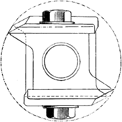
Fig. 3156.
Fig. 3156 shows a cutter head with two skew cutters.
The cutter head is provided with a cover or guard, which is arranged as follows: In the table is cut a groove or slideway, in which a slide fits, and to this is attached a thin sheet-iron guard. To the slide is attached a weight, which draws the guard back to the fence after the work has passed over the cutter head. By this means the guard covers all the knife edge that protrudes beyond the work, no matter what the width or thickness of the work may be; the guard can however be fixed in position when a number of pieces of the same size are to be planed.
The fence provides a guide surface for the work, and its face may be set at any required angle to the surface of the work table. Suppose, for example, that the sides or edges of a piece of work require to be at an angle of 100 degrees to the top and bottom surfaces, then the top surface may be planed first, and the fence being set at an angle of too degrees to the table surface, the top of the work may be pressed to the surface of the fence while fed across the cutter, and as a result, the side or edge will be planed at 100 degrees to the top.
ROLL FEED WOOD PLANING MACHINE.
Fig. 3157 represents a roll feed wood planing machine, designed and constructed by George Richards & Co., of Broadheath, near Manchester, England, the construction being more fully shown in the detailed figures following. The machine consists essentially of a framework, carrying a cutter head with two knives, and having a pair of feed rolls, in front and a pair behind it. The front pair feed the timber to the cutter head and the back pair deliver it from the cutter head.
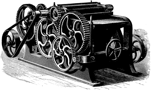
Fig. 3157.
Each pair of rolls is geared together, so that both the top and bottom rolls act to give a positive feed. Immediately in front of the cutter head and between it and the feed rolls (i. e. the front pair of rolls), is a pressure bar extending across the full width of the machine, and having at its lower extremity a steel spring which presses the work down to the table, and thus causes it to be planed of an equal thickness throughout its length. Immediately behind the cutter head and between it and the delivery rolls (i. e. the back pair of rolls), is a pressure bar that also extends across the machine and prevents the timber from rising up from the table after it has passed the cutters, all timber being found to have a tendency to rise after having been acted upon by the cutters. The arrangement of the feed rolls, delivery rolls and pressure bars is shown in Fig. 3158, in which t, t, t, represents three sections of the work table and w, w, a piece of work passing through the machine in the direction of the arrow. Feed roller f is fluted to increase its grip upon the work and insure a positive feed. The lower feed roller f′, and the lower delivery roller d′, are fixed in position, their upper surface projecting above the work table to about 1⁄100 inch. This is necessary to take the thrust of the upper rolls (f, d) and prevent them from forcing the work down upon the surface of the table with an undue amount of pressure, which would induce friction and consume an unnecessary amount of power in driving the rolls. The method of adjusting the lower rolls will be explained presently.
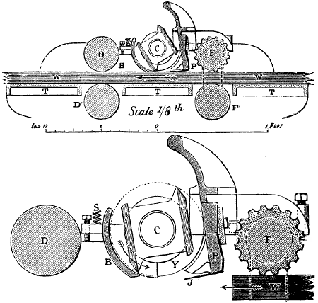
Figs. 3158, 3159.
Between the cutter head c and the feed roll f is the pressure bar p, and behind the cutter head is the pressure bar b, both these bars being more clearly seen in Fig. 3159, in which the work w is shown entering the machine, and the lower rolls and work table are removed.
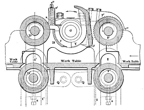
Fig. 3160.
Pressure bar p has at its lower end a steel spring j, Fig. 3159, and is supported at each end by circular links y, projecting into grooves provided in the main frame of the machine, as shown in Figs. 3160 and 3161, in which c is the cutter spindle, y the circular link at the end of pressure bar p, and y the circular link at the end of pressure bar b, the two fitting into the one stepped groove.
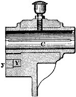
Fig. 3161.
This groove is concentric with the cutter spindle c, so that the pressure bars keep at a positive or equal distance from the edges of the cutter, no matter what the thickness of the work or the depth of the cut may be.
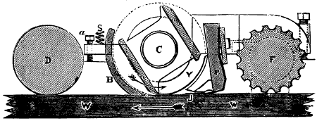
Fig. 3162.
In Fig. 3162, the work is shown passing beneath the two upper rollers, and the spring j (which extends the whole length of the pressure bar), is depressed from the weight of the bar. By this construction, the work is pressed to the table at a point as close as possible to the cutters. The pressure bar p cannot drop beyond a certain point, because of its tail piece y′, Fig. 3160, which rests on the top of the frame at y′′ when the bar p has fallen to its required limit.
The feed pressure bar p is bolted to its circular links, as shown in Fig. 3162, in which y is a part of the circular link which is bolted to the pressure bar p.
The delivery pressure bar b (Fig. 3160) is riveted to and forms part of its links y. It acts through the medium of spiral springs s, which are carried in cases or boxes s′, which overhang the end of the bar b. A set screw s′′ regulates the pressure of the spring, and a screw a (Fig. 3162) regulates the height of the pressure bar.
The adjustments of the feed and delivery rollers are made as follows:
The feed pressure is obtained through the medium of weights, shown at w, w′, in Fig. 3163, upon the bars a, a′, whose ends are pivoted to the lower ends of links m, n, the upper ends of which are pivoted to the side frame of the machine.
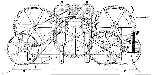
Fig. 3163.
Bar a engages or rests at e, on a lug or projection on the link i, which fits in a recess provided in the side of the frame. This link i, extends up and has a bearing to receive the feed roller (f, Fig. 3160), whose driving gear is shown at o.
It is obvious therefore, that the amount of pressure on the feed roller f may be varied by moving the weight w along the bar a.
Similarly for the delivery pressure roller, the weight w′ is adjustable along the bar a′, which is pivoted to link n, and rests upon i at e′. The link i′ is guided in ways in the side frame of the machine, and at its upper end carries the delivery roller d, whose driving gear is shown at o′ (Fig. 3163).
It is obvious that there are bars a, a′, and links i, i′, on both sides of the machine, so as to adjust the feed rollers at both ends.
The work table and the two lower rollers are adjusted for different thicknesses of work as follows:
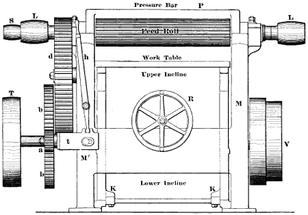
Fig. 3164.
Between the two main side frames m and m′, Fig. 3164, are two frames having corresponding inclines or slideways, of which the upper carries the work table and the lower rolls.
The lower incline sits on ways k, k, Fig. 3164, cast on the side frame, and is capable of being moved endwise by means of the hand wheel r, Figs. 3163 and 3164, which operates a screw threaded into the lower incline. When the lower incline is moved endways, the upper one, which carries the work table, is moved vertically, and as the lower feed rolls are carried by the upper incline, and the upper rolls are guided to move vertically only, the lower rolls maintain their position beneath the upper ones, or in other words, the table and lower rolls move together in a vertical direction only, when the lower incline is operated.
The lower rollers run in bearings formed in the links q, q, Fig. 3160, which are pivoted at their other ends to the upper incline. On the sides of the incline are lugs through which pass adjustment screws z, which by operating beneath the outer ends of the links q, q, adjust the heights, bearings of the lower rollers so that the uppermost point on the circumference stands about 1⁄100 inch above the level of the work table surface.
The upper surface of the lower incline is shown by the dotted line f, f, f, in Fig. 3163.
We may now consider the means employed to drive the rolls, first remarking that the upper rolls f and d, are given a motion slightly quicker than the lower ones, so as to cause them to clean themselves (from particles of wood that might otherwise cling to them), by a sort of rubbing action which is due to their velocity being greater than the lower rolls and the work. This rubbing action is due to the fact that the work has the slower motion of the lower rollers, resisting the quicker motion of the upper ones, and as a result there is a certain amount of slip between the upper rollers and the work.
Another and important feature, is that the upper delivery roller (d, Fig. 3160), is placed from 1⁄4 to 1⁄2 inch nearer to the cutter head than the bottom delivery roll, which assists in keeping the work down upon the table.
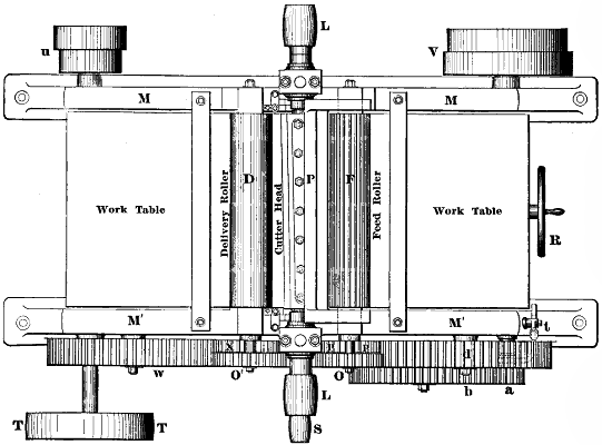
Fig. 3165.
The mechanism for driving the feed rolls is shown in Figs. 3163, 3164 and 3165, in which l, l are the pulleys which receive motion from a countershaft, and drive the cutter head, being fast upon its shaft, as is also the pulley s, which connects by belt and drives pulley t, on whose shaft is the stepped pulley u, which connects by a crossed belt to pulley v, which drives the feed gear through the medium of the pinion a. The two steps on pulleys u and v, obviously give two rates of feed.
The pinions o and o′, both receive motion from the gear wheel e, this part of the gearing consisting of gears a, b, c, d and e, and as both pinions receive motion from the same gear, their revolutions are equal. The lower feed roll is driven by the pinion p, which gears with and is driven by wheel d, whose face is broad enough to meet p, which sits nearer to the frame than pinion o does, so that the teeth of p may escape those of o.
Now the velocities of all the wheels o, o′, e, d and p, will be equal at the pitch circles, because they constitute a simple train of gearing. Thus if d moves through a part of a revolution equal to the pitch e, then o and o′ will move through the same distance, because the wheels are in continuous gear. Now as d drives p, therefore the velocity of p must at the pitch circle be the same as d, let the numbers of teeth in the respective wheels be what it may, and it follows that the velocities of o, e, d and p are at the pitch circles equal. But by making the diameter of the upper roll greater than the pitch circle of its gear o, and the diameter of the lower roll correspondingly less than the diameter of the pitch circle of its pinion p, the velocity of the circumference of the upper roll will be greater than that of the lower roll, and the rubbing action before referred to with reference to the upper roll will thus be induced.
Referring now to the lower delivery roll, its pinion x receives motion through gear w, which is also driven by gear e, which has a broad face so as to gear with x, which is behind and below gear o′. In this case the circumstances are the same, as will be seen from the following.
An inch of motion of the pitch circle of e will produce an inch of motion at the pitch circles of o′ and of w and x, hence the velocities of the pitch circles will be equal, and if the diameters of the upper and lower rolls are equal, or the same as the pitch circles, the velocities of the circumferences of the respective rolls will be equal, but by making the diameter of the upper delivery roll greater than that of the pitch circle of its pinion, and that of the lower roll less, a rubbing action is induced between the roll and the work, and this rubbing action will keep the roll clear of any dust, etc., that might otherwise cling to it.
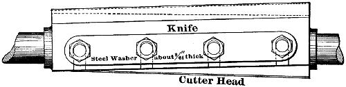
Fig. 3166.
The cutter head is formed triangular, as in Fig. 3166, carrying three knives. The knives are set at an angle to the axis of the cutter bar or cutter head. When the knives are at an angle, they take their cut gradually, and the cutting action is more continuous, which diminishes the vibration of the machine, and causes the finished surface to be smoother. Furthermore, the knives take a shearing cut, and therefore cut more easily and freely.
In some practice the knives are made spiral, but spiral knives are difficult to bed properly to the cutter head, and also difficult to grind. The cutter head is made of a solid mild centre steel forging, and runs in phosphor bronze journals, in which it has about 1⁄8 inch end play, which tends to distribute the oil along the bearing. It is driven by a pulley at each end, the pulleys seating on a cone.
The amount of skew is about 3⁄4 inch for a cutter head carrying a knife 30 inches long, and about 3⁄8 inch for a cutter head whose knives are 10 or 12 inches long.
Large
image
(151 kB).
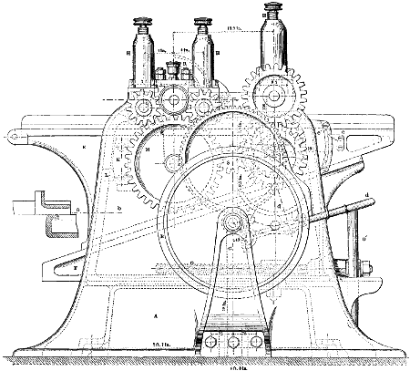
Fig. 3167.
Figs. 3167 and 3168 represent a machine in which there are three feed rolls and one delivery roll, all being driven.
Large
image
(150 kB).
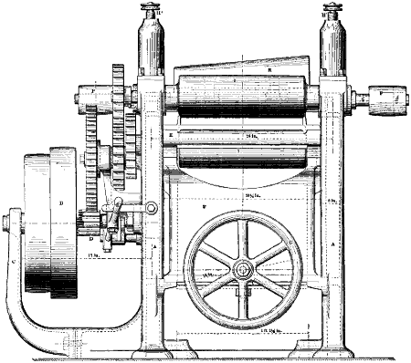
Fig. 3168.
First there is the pair of feed rolls the bottom roll of which is set sufficiently above the surface of the table to relieve the work of friction upon the table.
The work next meets an upper feed roll that acts to force the work down to the table surface (there being in this case no lower feed roll).
After passing the knives, the work is carried out by a delivery roll that also acts to keep the work down to the table face.
All three upper rolls are provided with rubber springs in the casings h, h′.
p, p, are the pulleys for the cutter head and b, those for the feed works, which have two speeds. The feed is thrown in and out by the lever d, which moves the pinion d endways and engages or disengages it from its gear wheel.
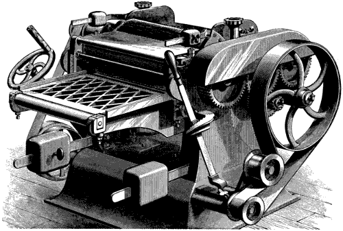
Fig. 3169.
Figs. 3169, 3170, 3171 and 3172 represent a pony planer, by P. Pryibil.
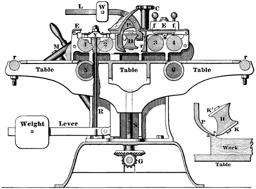
Fig. 3170.
Referring to the sectional view Fig. 3170, the work table slides in vertical slideways s, in the side frames, the elevating screw being operated by the bevel gears at g, which receive motion from the hand wheel m in Figs. 3170 and 3171. There are four upper rolls, marked 1, 2, 3 and 4 respectively, and of these the first two are fluted in the usual way. There are two lower rolls, marked respectively 5 and 6. The fluted feed rolls 1 and 2 are weighted, the weight lever acting on the rod r, which at its upper end connects to the cap y, which covers the bearings of feed rolls 1 and 2. By this construction the two rolls are acted upon by the same weights and levers, the rolls being of course weighted at each end, or in other words on both sides of the machine.
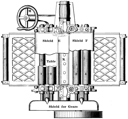
Fig. 3171.
The delivery rolls 3 and 4 receive their pressure by the construction shown in Fig. 3172, the bearings of the rolls being held down by rubber cushions receiving pressure from the cap e, screwed down by the bolt and nut.
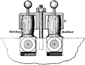
Fig. 3172.
The rolls 5 and 6 are idle rolls, and are set to just relieve the work from undue pressure on the work table.
By this construction of feed mechanism the following ends are attained. First, sufficient feed power for heavy cuts is obtained without driving the lower rolls. Second the work is held to the table on both sides of the cutter head, hence there will not be left on the end of the work the step that is left when but two upper and two lower rolls are used, and which occurs because the work falls after leaving the feed rolls, whereas, in this machine the work is held to the table by rolls 2 and 3.
The cutter head h, Fig. 3170, has in front of it the pressure bar p, whose lever is shown at l and the weight at w. On the delivery side of the cutter head is a pressure bar r, which is acted upon by a spiral spring in the box c. In the engraving to the right of Fig. 3170 the knife k is shown in action on a piece of work, and it is seen that the end of the pressure bar p coming close to the edge of the knife prevents the pressure of the cut from splitting or splintering off the end of the work at a, and therefore acts as what is termed a chip break. Furthermore, the sides of the cutter head between the knives being hollowed out gives the shavings s room to curl in and prevent the work from splintering at the end when the cut is terminating.
Balancing Cutter Heads and Knives.—Planer knives must be balanced as accurately as possible, in order that they may run steadily and smoothly, and therefore produce smooth work.
The first requisite for proper balancing is that the cutter head itself be properly balanced, and in order that this may be the case the faces forming the knife seats must be equidistant from the axis of the cutter head, and the journals must run true, being best tested on dead centres. The holes for the cutter bolts should all be drilled to the same depth, and tapped equally deep. The faces or seats for the knives should be parallel one to the other, and this may be tested by a pair of straight edges, one pressed to each face and the width between them measured at each end, or if a long surface plate is at hand, one face of the head may be rested on the surface plate, and the straight edge ruled on the other face, and its distance measured from the surface plate at each end, with a pair of inside callipers delicately adjusted.
A straight edge rested lengthways along the knife seat of the head and projecting over the journal will show whether each knife seat is equidistant from the journal as it should be, the measurement being taken with a pair of inside callipers adjusted to just sensibly touch the journal and the straight edge. This measurement should be taken at each end of the head.
In all tests made with straight edges, the straight edge should be turned end for end and each measurement repeated, because, if the straight edge is true, turning it end for end will make no difference to the measurement, while if the straight edge is not true the measurement will vary when the straight edge is reversed.
If the cutter head is square, the straight edge tests may be applied to all four of its faces, and they may then be tested with a square, and if the head shows no error under these tests, and the bolt holes or slots are of equal diameter and depths, the head will be correct as far as it can be tested without running it.
A cutter head may be roughly tested by placing it between the lathe centres, both centres being oiled and delicately adjusted so as to just prevent end motion of the head without perceptible friction when the head is revolved by hand.
The first thing to test is whether the journals run true, which may be tested by a pointer fastened in the slide seat, and moved up to just touch the journal. The pointer should be soft, and not a cutting tool, unless indeed it be set so high in the slide rest that it cannot cut.
If the journals do not run true, the next thing to test is whether the body of the head runs true to the centres, which may be done by first setting a pointer to just touch the extreme corners of the head at each end and in the middle of its length, and if there is an error in the same direction as the test at the journal shows, then the centres of the head are out of true, and must be corrected before a test of this kind can be proceeded with.
But the body of the head may show true at the corners while the journals do not run true, and if this is the case we may further test the body of the head as follows:
With the lathe slide rest at one end of the head we may set a pointer so that it will just pass on the flat of the cutter seat and make a mark when the slide rest is traversed along the lathe bed. We then move the slide rest so as to bring the pointer to the journal end of the head; give the head a half a revolution on the centres and try the pointer on the flat of the cutter seat, and if it makes a mark of equal strength, then two faces of the head are equidistant from the axis of the head.
The next thing to do is to make the same test at the other end of the head, and in order to do this without moving the pointer, and therefore without altering its adjustment, we must move the slide rest so as to bring the pointer opposite to the lathe centre, and out of the way of the body of the head, and take the cutter head out of the lathe and turn it end for end, and then repeat the test with the pointer, which will show whether both ends of those two flats are alike.
This test we repeat on the other two faces of the head, and if they show true, then the head is true, except the journal, which must be made true with the head.
This testing will clearly show any want of truth in either the head or the journals, and in what direction correction needs to be made.
Now suppose the above tests do not disclose any error, either in the journals or in the head, and we may continue the tests by revolving the head by hand between the dead centres, and apply the pointer to the journals while the head is revolved as quickly as possible; as, however, the head cannot be revolved very fast in this way, we may adjust the lathe centres as before described, and revolve the head as rapidly as possible by hand, and letting it come to rest mark which side is at the bottom, and if on several tests the same side comes to the bottom of the plane of revolution at each test, that side is the heaviest and must be corrected. If it is found to be a flat side or cutter seat that comes to rest at the bottom, the correction can be made by deepening the bolt holes on that side, measuring to see which bolt hole is the shallowest, and making all as nearly as possible equally deep.
If the head has T slots instead of bolt holes, the slots may be cut or filed out to effect the balance, care being taken to make the slot equal in distance from the edges of the cutter seat face.
The next essential in order to have a properly balanced cutter head is that the bolts and nuts all weigh alike, and that the bolts be of the same length. The bolts should be turned to an equal diameter of equal length and threaded for an equal distance along the body of the bolt, and the nuts should be of equal depth and all fit accurately to the same wrench, and the weight of the bolts and nuts when put together may then be equalized by reducing the heads of the heavy ones.
We now come to the balancing of the knives, which must be made of equal thickness and width throughout, with the slots for the bolts of equal widths and depths.
The knives require to be as accurately balanced as it is possible to make them, for otherwise they will cause the head to jar and vibrate violently, thus producing rough work. The knives weighed individually may be of the same weight, and yet the head may run out of balance by reason of one end of a knife being heavier than the other end.
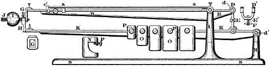
Fig. 3173.
Fig. 3173 represents a machine constructed by J. A. Graham & Co., for balancing planer knives, moulding knives, cap screws, and knives in rotary cutter heads of all kinds.
Let it be supposed that the knives are the same specific weight, but that there is an excess of weight at one end; when revolving on the head, a violent jarring or throwing will be caused by reason of the excess. The knives could be reduced to the same specific weight by the aid of common grocers’ scales, but the ends could not be made the same proportional weight as on such balance.
In the cut s s is the base of the scale; l, m the standards for the support of the scale beams b b and k k.
d, d′ are two pivots of the scale beams.
d is the loop on which the pivot d works.
e is a joint in the loop.
d′, e′, and f show the loop and connection.
c is the sliding table which has the stop c′, and is adjustable for different lengths of knives.
a a is a knife in position for balancing endwise.
g is a slotted piece, and is held to the scale beam by the screw v. The slot in g is shown at g′, and limits the travel of the scale beams.
h is an angular piece fastened to the lower scale beam, and receives the screw j.
i is a small weight used for fine adjustment.
o, o are weights which slide along the scale beam k k, and are held in place by the thumb screws p, p.
n shows side view of weight, which is so constructed as to allow it to be easily removed. In using the machine the lightest cutter or knife of the set is first found and its two ends balanced, by turning it end for end on the scales, and reducing the weight of the heavier end. The other knife or knives are then balanced without disturbing the adjustment of the machine as made for the first knife.
ENDLESS BED OR “FARRAR” WOOD SURFACING MACHINE.
This class of machine has a bed composed of slats which are connected together and driven by a chain.
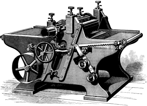
Fig. 3174.
Fig. 3174 represents an endless bed double surfacer constructed by the Egan Company. The upper cylinder may be raised or lowered to suit the thickness of the work. The front feed roll is in two sections, enabling two boards of unequal thickness to be planed simultaneously to an equal thickness. These rolls are held to the work by a leaf spring, as shown in the cut, the tension on the spring being adjusted by the screw at d, d serving as a check-nut.
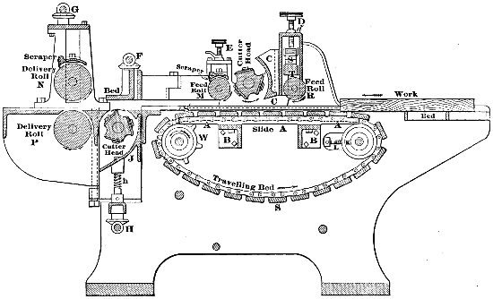
Fig. 3175.
A longitudinal section through the centre of the machine is shown in Fig. 3175. The spring s bears at each end on a block t, which carries the bearings for the feed roll. Feed roll m is held down by the screws e, e, acting on a rubber cushion or spring, and is provided with a scraper to clean it from dirt, etc.
The travelling bed is composed of slats s connected together by the chain shown, and resting upon slides a, a, supported by the girts b, b.
The chain is operated by the spur or sprocket wheel w, and is therefore pulled and not pushed, which tends to keep it under tension, and therefore rigid upon the top side.
The ends of the slide a, a are depressed so that the slats shall not tilt up at one corner above the level of the slide when in the positions denoted by s′.
The lower cutter head is carried in a sliding head or frame j, adjusted for height by the gears at h, which operate screw h, while the bed above it is adjusted by the gears at f. It is obvious that the bottom surface of this bed is set at the same height as the lowest point in the path of revolution of the cutting edges of the knives of the front cutter head or cylinder. The upper delivery roll n is provided with a scraper.
PLANING AND MATCHING MACHINE.
Planing and matching machines that are made narrow to suit the planing and matching of boards for flooring are sometimes called flooring machines, the distinctive feature of a flooring machine being that it is (unless in the case of a double machine) made narrow (because flooring boards are narrow), and this makes the machine very stiff and capable therefore of a high rate of feed and speed.
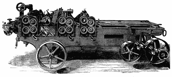
Fig. 3176.
Fig. 3176 is a general view, and 3177 a longitudinal section through a standard planing and matching machine of recent design, constructed by Messrs. J. S. Graham & Company. The plank passes through two pairs of rollers before meeting the front cutter head. The side heads then come into operation cutting (in the case of flooring) the tongue on one side of the plank and the groove on the other, the under side of the plank being dressed last.
The machine is built in three widths viz., 8′′, 14′′ and 26′′, each planing to 6′′ thick and matching as wide as it planes.
In place of matching heads, heads for beading, rabbeting, or fancy siding may then be used.
Large
image
(76 kB).
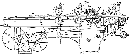
Fig. 3177.
The board r (Fig. 3177) is fed in over the grate m′ until it reaches the rolls e and f′, which are held in place by the boxes fitted to the roll stand n′, and brought to bear on the lumber by means of the screw a′, equalizing bar m and nuts p, p, together with the lever y y and the weight x.
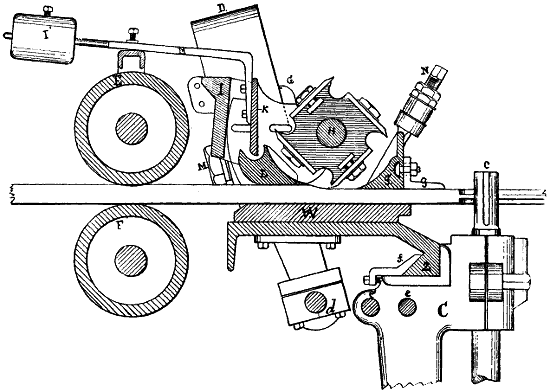
Fig. 3178.
After the lumber leaves the second pair of rolls, it runs over the bed plate w (Fig. 3178) and under the shoe l, the duty of which is to hold the board firmly against the bed plate, and also to break the chips on a heavy cut. After leaving the shoe it is operated on by the upper cutter head h, then it passes beneath the pressure bar g, which holds the lumber firmly while it is acted on by the matcher c.
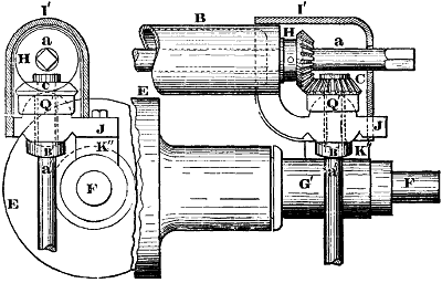
Fig. 3179.
It then passes beneath the cleaner e′′ (Fig. 3177) and under the delivering roll, which is held down by the weight u in connection with the lever v and screw a′, the top which is shown at c (Fig. 3179). The board then passes underneath the pressure bar q (Figs. 3177, 3180) and over the under cutter s, from which it passes finished.
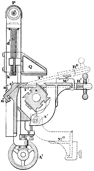
Fig. 3180.
The pressure bar q is moved up and down by turning the shaft a′′, the motion of which is given to the screw h′ by means of a pair of bevel gears. k′ is also a scraper that cleans the board before it passes under the pressure bar q. The under cutter is adjusted for depth of cut by turning hand wheel a′, which moves the screw u′. The rolls are raised and lowered by turning the shaft at p (Fig. 3176).
In feeding two boards through the machine, one thicker than the other, that end of the roll that passes over the thick board can raise up without taking the pressure off the thin one at the other end of the roll. This raising mechanism is shown in Fig. 3179. The bevel gear c works over a ball joint q′. The shoulder b′ on the screw a′ works on the under side of the ball q′. The shaft a passes through the tubular shell b to the opposite end of the roll. The cross tie j is bolted to the roll box k′′.
c, Fig. 3178, shows matcher hanger in position. It is gibbed to the bed plate z by the gib f, which is so constructed as to be free from dirt. The sliding gib f is adjustable for wear. One matcher hanger is moved by the screw e, the other by e′. The left hand matcher hanger is moved by the shaft l′ (Fig. 3177), which passes along the side of the machine until it reaches the shaft e, where its motion is imparted to the screw by means of a pair of spiral gears. An index at the rear of the machine enables the operator to set the matcher heads to any desired width. The right hand matcher hanger, together with the guide, can be moved across the machine by turning the screw e′ at the side of the machine (Fig. 3176).
The upright d which carries the pulley which drives the top cutter head, or cylinder as it is sometimes termed, is set at an angle so that the cylinder belt will always be of the same tension.
The top cylinder is raised by the shaft d (Fig. 3176) and screw b. It is held in place by the nut m (Fig. 3177). The bar i ties the cylinder boxes together. k is held down by the weight i, and yields with the pressure bar l.
The spindle of the matcher c′ (Fig. 3177) is driven by a belt which comes from the pulley h and passes over the guide pulley k, and then to the pulley b′.
The lower end of the matcher is held in place by being gibbed to the cross tie p′, Fig. 3177, which is adjusted and kept in position by the screw o′.
s′ sustains the matcher spindle by means of an adjustable step.
y′, Fig. 3176, is the feed shaft which drives the gearing that operates the rolls. The pulley that drives the feed shaft is shown at l′ (Fig. 3176). The belt passes over this pulley and under and over the tightener pulleys w′, w′, then to the pulley u′ which is on the feed shaft y′.
The apron m′ in front of the under cutter s (Fig. 3180) is easily dropped to m′′ by loosening the nut r′ and releasing the bolt t′ so as to allow the apron m′ to drop.
This enables the operator to have free access to the under cutter for sharpening knives, etc. z′ is the bed plate over which the lumber passes before it reaches the under cutter.
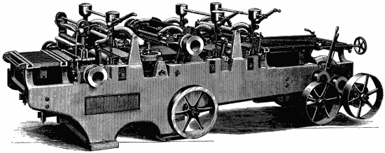
Fig. 3181.
A planing and matching machine designed and constructed by Messrs. London, Berry and Orton is represented in Fig. 3181. In this machine the upper surface of the board is surfaced first, and the matching second, the under surface being operated upon the last. The method of suspending the upper feed rolls of this machine is shown in Fig. 3182, in which a is an upper and b a lower feed roll. The upper roll a is suspended by the link c, which is supported by the link d, and also by link e, these three links forming a parallel motion which guides a in a vertical line.
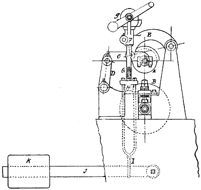
Fig. 3182.
At f (which is fast to e) is a bearing for the screw g, and the pair of bevel gears g that drives it. This screw threads into the nut h on the rod i, which receives the pressure of the bar j and weight k.
The lower feed rolls being larger in diameter gives them increased grip on the work, and gives it a better base, and also makes it enter and leave the rolls easier.
Each matcher bracket is fitted with a screw by which it can be moved at will across the machine, and by turning one other screw with the same wrench that moves the others, both brackets are firmly set to the slide and all screws held firmly. There are three changes of feed. The top cutter head is provided with improved pressure bars, which are set to or from the head by means of a double eccentric, which, while they can be set at any desired distance from the knives, limits their movement when moved towards them, rendering it impossible to get them into the cutters.
TIMBER PLANER.
The term timber planer implies that plain knives only are used in the machine, which is therefore intended for producing plane surfaces. It also implies that the machine is designed for heavy or large work, such as is found in ship yards, bridge construction or car works, etc., etc.
In such work the cuts taken by the machine are sometimes very heavy, and as a result the feed works of the machine require to be very powerful and positive.
Large
image
(148 kB).
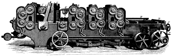
Fig. 3183.
Fig. 3183 represents a timber planer designed and constructed by J. S. Graham & Co., to plane all four sides of the timber at one passage through the machine.
The timber passes through three pairs of feed rolls before reaching the first cutter head, which planes the bottom surface.
It then passes to the side heads, which dress both sides simultaneously, and then passes beneath the cutter head that finishes the upper surface, and is finally delivered from the machine by a pair of delivery rolls.
The work is passed over roller b, the fence or gauge being shown at b′. 1 and 2 are the first pair of feed rollers, a and b being merely adjustable intermediate wheels, which by means of the pieces c′, b′, may be set so as to connect rollers 1 and 2 together, whatever their distance apart may be, or in other words whatever the thickness of the work may be.
From 1 and 2 the work passes to the second pair of feed rolls 3 and 4, c and d being the intermediates.
Similarly 5, 6, 7 and 8 are feed rolls, and e, f, g, h intermediates. The first head is shown at k′, the side heads at h, and the last head at i′, the latter being carried on a sliding head j, which is secured in its adjusted position by nuts i. On the side of the frame d on which j slides is a graduated index to denote the adjustment of the head i′.
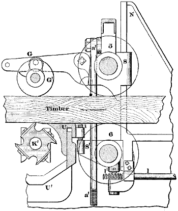
Fig. 3184.
The construction of the parts in immediate connection with the front cutter head is shown in Fig. 3184. n is the frame corresponding to n in Fig. 3183, the rolls 5 and 6 also corresponding in the two figures.
Upon n is a slide s having an arm g, carrying the roll g′, which holds the timber down to the cut of the cutter head k′. The pressure of roll g′ to the work is given through the medium of the rod a′, which receives the pressure of the equalizing bar x, Fig. 3183.
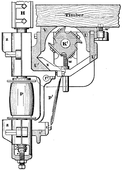
Fig. 3185.
The bottom surface of the timber passes over the bed plate u, Fig. 3185, which raises and lowers with the lower feed rolls, being connected by the screw i, Fig. 3184, to the bearing box of feed roll 6.
All the lower feed rolls are operated simultaneously by means of the rod l, having for each lower feed roll a worm, driving a worm wheel l′ on a screw threaded into a hub m in each feed roll bearing; the crank for operating l is seen at p, Fig. 3183.
The passage of the timber through the machine is continued in Fig. 3185, in which it is seen that after the lower surface of the timber has been planed it passes from the cutter head k′ to a bed plate v and is thus supported by a flat and true surface while the side cutter heads plane the two sides, one of these side heads being shown at h. The side heads are carried in hangers, one of which is shown at p′. It is gibbed to the under cutter frame u′ by the sliding gib x, the left hand head h being moved across the frame by the screw f′. The hanger is held at the bottom by the gib t and the cross tie t′. p is the pulley for the side head h, the end wear of whose shaft is taken up by the adjusting screw s′, r′ being a leather washer, and r the end of the shaft.
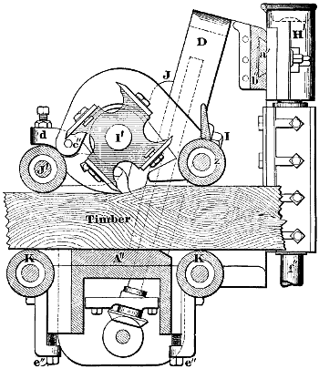
Fig. 3186.
The top box h′ moves across the machine in the slideway b′′, Fig. 3186, a′′ being a part of the box h′.
Upon leaving the side heads the timber will have been planed on three sides and the side surfaces dressed to a right angle with the bottom surface.
It is then guided to the upper cylinder as follows:
The friction rolls k, k are to relieve the bed a′′ from the pressure due to the feed roll z′ and the roll j′, which holds the timber after it has left the cutter i′, and thus prevents it from vibrating. After leaving the pressure roll j′, the timber passes under the scraper d′, Fig. 3183, and thence to the delivery roll 7, which is held down by the weight l, in connection with the lever l′.
By means of this construction all the cutter heads act upon the timber within the short distance of 221⁄2 inches, while the side heads act within 81⁄2 inches of the under cutter. This is desirable, being conducive to the production of true work, which it is more difficult to produce in proportion as the cutter heads are wider apart. This machine will joint as narrow as 2 inches, and plane as thin as 3⁄4 inch.
The upper cylinder i′, Fig. 3183, is adjusted for height or thickness of cut by means of the screw f, and is locked in its adjusted position on d by the nut i.
The feed is started or stopped by operating the hand wheel o′.
The upper rolls are raised or lowered simultaneously by power, by means of the shaft s, and the bevel gears r, which operate the screw a′.
The upper cylinder is driven by belt from the pulley q, the under cylinder from q′ (both these cylinders being driven from both ends). p′ is the driving pulley for the feed belt, which passes to n′, which, through k′′ and y′, drives y, which drives the feed rolls.
The machine will feed from 25 to 60 feet per minute.
PANEL PLANING AND TRYING-UP MACHINE.
This class of machine is employed for the production of true surfaces, and is now used upon much of the work that was formerly assigned to the Daniels class of planing machine. In this machine, as in the case of the Daniels planing machine, the work is secured to the table, which travels to carry the work to the feed.
Fig. 3187 represents a machine by J. Richards, in which a cutter head with skew cutters is employed, and a pressure roll is placed in front and at the back of the cutter head, the construction being as follows:
VOL. II. TRYING‑UP MACHINE. PLATE XXVI.
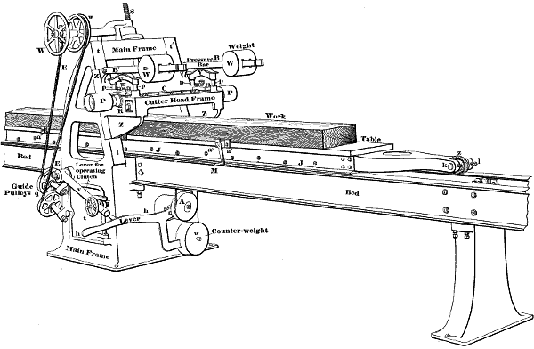
Fig. 3187.
Upon the main frame are the slideways t, t′, upon which the cross-head or cutter head frame z is carried, the elevating screw s raising or lowering the frame z, to suit the thickness of the work. The cutter head c, whose driving pulleys are shown at p, p, is carried in frame z, which also carries the pressure roll in front of the cutter (the bearing for this roll being shown at r), and a similar roll behind the cutter. To the frame z are pivoted the pressure bars b, b′, weighted with weights w. These bars rest on the cross-heads y, whose pins p act on the bearing boxes of the pressure rolls.
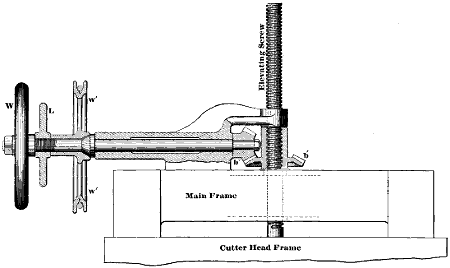
Fig. 3188.
The cutter head frame may be raised or lowered, for varying thicknesses of work, either by hand or by power. The hand movement is obtained from the hand wheel w, Fig. 3188, which operates bevel gears b′′ and b′, the latter being threaded to receive the elevating screw.
The power or belt motion for raising or lowering the cutter head frame is obtained from rope wheel w′, which receives motion from the guide pulleys shown in Fig. 3187. The wheel w′ drives its shaft by the friction cone of its bore, which is forced against the corresponding cone on the shaft by the hand nut l. The handle v, Fig. 3187, is for operating the upper guide pulley q, which acts as a belt-tightening pulley as well as a guide pulley, and the hand wheel t holds v in its adjusted position. When v is pushed downwards the rope (e) is loosened upon the pulleys, and both rope and pulleys remain idle.
The pulley that drives rope e is shown in Fig. 3189 at r.
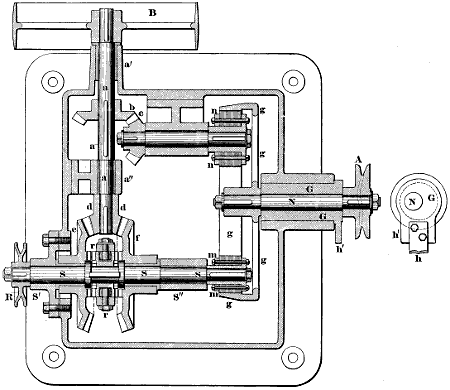
Fig. 3189.
The feed motions for the work table are shown in Fig. 3189, and the construction is such that for ordinary work the table has a quick return motion, while for heavy work the feed and return motions of the table are speeded alike.
The driving pulley b, Fig. 3189, for operating the feed mechanism, receives motion by belt connection from the countershaft, and drives the shaft on which are the bevel gears b and d, and from these gears the feed motion and quick return are derived, while from gear e and pulley r the cutter head may be raised and lowered by belt power as occasion may require. Beginning with the feed motion, the gear d drives gears e and f, which are a working fit on the shaft s. Between these two gears is the clutch r, r, which is operated by the handle shown in the perspective view, Fig. 3187, at v.
To operate the feed, clutch r is operated to engage gear e with the shaft s, upon which is the friction wheel m, which engages with the internal surface of the wheel or drum g, which drives the rope wheel a, which drives the rope for the work table traverse—wheel a and the rope being seen in the perspective view, Fig. 3187. The shaft n has bearing in a piece that is virtually a sleeve eccentric, because its bore is eccentric to its circumference; to this sleeve is attached a lug h′ to which the handle h, Fig. 3187, is bolted. Now suppose that handle h is depressed, and then g will partly revolve wheel g and cause it to engage with the friction wheel m, which will drive g, and therefore a.
Diametrally opposite to m is a friction wheel n, which is driven by the bevel gear c, and which is brought into or out of action with g by the eccentric action of sleeve g, it being obvious that when the sleeve g moves g in the direction of n, m is engaged and n disengaged from contact with g. Raising the handle h therefore places n in gear with g, which revolves it in the direction necessary to draw the work table on the back or return stroke.
The return motion of the table is more rapid than the feed motion because gear c is of smaller diameter than b, and n is larger than c and than m.
In the case of heavy work, however, the return motion may be made to have the same speed as the feed motion by simply moving the clutch r so as to engage wheel f with the shaft s.
The rope groove in the pulley a is waved as denoted by the dotted lines, and this prevents the rope from slipping, notwithstanding that the rope envelops but half the circumference of a. The wire rope from a operates a drum, in which are waved grooves for the table traversing rope which winds around this drum, and attaches to pins (k, Fig. 3187) carried in brackets at the ends of the table, and one of which is shown in Fig. 3187, at z.
The slack of the rope is readily taken up (as occasion may require) as follows:
The pin k, to which the rope is fastened, has at one end a squared head to receive a wrench to revolve the pin and wind up the rope, set screw l locking the pin after the rope tension is adjusted.
We have now to explain the method of holding the work, which is as follows:
The side frames forming the bed are bolted to the main frame and form the ways on which the work table travels. The table frame j, Fig. 3187, is provided with rollers, which rest on the upper surface of the bed and reduce the friction.
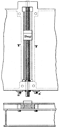
Fig. 3190.
The table is made in convenient sections bolted to the table frame j, and at their points of junction the work-holding dogs are placed, the construction being shown in Fig. 3190, in which t′ is the end of one, and t′′ the end of another section of the table. Referring now to Figs. 3187 and 3190, upon the edge of the table are the abutment pieces a′, a′′, against which the work is pulled by the dog, which is operated by the screw, which is squared at its outer end to receive the handle m, Fig. 3187.
The rate of work feed is 30 feet per minute and the quick return motion is 60 feet per minute.
MOULDING MACHINES.
In moulding machines for light work the feed rolls and cutter head overhang the frame, such machines being designated as outside moulding machines.
Fig. 3191 represents a machine of this class constructed by J. A. Fay & Company.
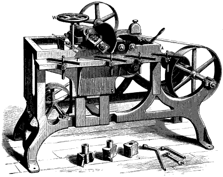
Fig. 3191.
The table t slides on vertical ways on the main frame, being adjusted for height by the hand wheel w.
The work while fed over table t is pressed against the vertical face a by the four springs shown, whose pins swing to suit the width of the work.
The two feed rolls are made up in sections or discs and the pressure bar is pivoted and has the weight shown to adjust its pressure to suit the work, and is combined with the bonnet whose shape throws the shavings outwards from the side of the machine. The particular machine here shown is constructed substantially enough to permit of its being used for light planing or work not exceeding 6 inches in width, a head with planing knives being shown in place on the machine. In a machine of this kind it is essential that the cutter head spindle and its bearings be rigid, and with ample journal bearings and free lubrication to prevent wear, and for these reasons the arbor is of steel running in self-oiling bearings of large diameter. The arbor frame is capable of lateral movement to enable an accurate adjustment of the cutters to the work.
The term sticker, as applied to a machine of this class, means that it is suitable for light work such as window sash and door stiles, blind slats, etc., etc.
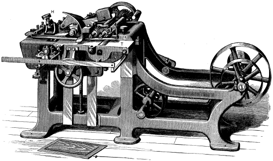
Fig. 3192.
Fig. 3192 represents a machine termed by its manufactures (the Egan Company) a “double head panel raiser and double sticker combined.” The term panel raiser means that the edges of the work may be dressed down so as to leave a raised panel. To fit the machine for such work the bed or table t is made wide.
The upper feed rolls are in sections, and the lower one extends nearly across the bed. The upper feed rolls are held down by a spring, whose tension may be regulated by a hand wheel with an adjustment at the back end to give a lead to both rolls. By this is meant that the plane of revolution of the feed rolls inclines toward the cutter head so that as the rolls feed they exert a pressure on the work, holding it securely against the face a.
A long spring extends from the front of the feed rolls past the back or bottom cutter head, passing as shown beneath the pressure bar, and is adjustable for height from the bed or table face t by having its ends pass through two studs in which they may be secured by set screws. This serves to keep the work down to the surface of t.
The cutter heads for panelling have three cutters set askew or at an angle to their plane of revolution so as to give a more continuous and a shearing cut, which is conducive to smooth work.
The bed above the lower cylinder is adjustable for height by means of the screw at h.
MOULDING CUTTERS.
In the ordinary or common form of moulding cutter, the front face is flat and the lower end is bevelled off and filed to shape so as to give the required shape and keenness to the cutting edges, Fig. 3193 giving examples of such cutters.
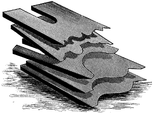
Fig. 3193.
Cutters of this class must be sharpened by filing the bevelled edge, which requires considerable skill in order to preserve the exact shape of the moulding.
SOLID MILLED CUTTERS.
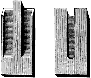
Fig. 3194. Fig. 3195.
In the solid milled cutter the bevelled surface at the cutting end of the cutter is a plane, and a curved, stepped or other shape is given to the cutting edge by cutting or milling suitably shaped recesses on the front face of the cutter as shown in Figs. 3194 and 3195, the former being a tongue cutter for cutting a groove, and the latter a grooved cutter for cutting a tongue.
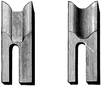
Fig. 3196. Fig. 3197.
Other examples for such cutters are given as follows:
Fig. 3196 represents a cove cutter and Fig. 3197 an ogee. Fig. 3198, a double beading, and Fig. 3199 a bevel cutter, and it is obvious that by a suitable arrangement and shape of groove cutting edges of any of the ordinary forms may be produced.
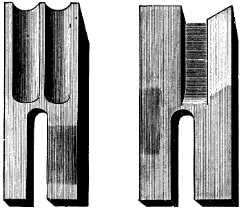
Fig. 3198. Fig. 3199.
The advantages of such cutters are that the plain bevelled face or facet of the cutter may be ground (to sharpen the cutter) on an ordinary emery wheel or grindstone, and the shape of the cutting edge will remain unaltered, providing that the cutter is always held to the grinding wheel or stone at the same angle, so that the length of the bevel remains the same.
A common practice is when making the cutter to so regulate the depth of the grooves or recesses in its face that the cutting edge will be of the required shape when the length of the bevelled facet is equal to three times the thickness of the cutter.
The method of finding the shape of cutter necessary to produce a given shape of moulding has been fully explained on pages 80 to 85, Vol. II.
Various forms of side heads are shown in the figures from 3200, to 3207. Fig. 3200 is a two-sided plain head, or in other words two diametrally opposite sides of the head are provided with bolt holes, for cutter fastening bolts. Fig. 3201 represents a four-sided slotted head, each side having T grooves, so that the cutter may be adjusted endways on the head. This enables the use of four narrow cutters, thus taking the cut in detail as it were.
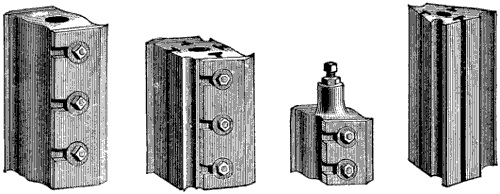
Fig. 3200. Fig. 3201. Fig. 3202. Fig. 3203.
The two-sided head shown in Fig. 3202 is provided with a set screw, by means of which a delicate adjustment of the height of the cutter may be made. Fig. 3203 represents a three-sided slotted head, or in other words T-shaped grooves, and not bolt holes are used.
CUTTER HEADS WITH CIRCULAR CUTTERS.
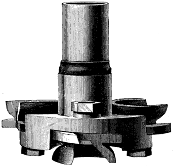
Fig. 3204.
This form of cutter head was invented by S. J. Shimer, and are generally known as Shimer cutter heads. The principle of construction is shown in Fig. 3204, which is for an ogee door pattern.
The cutters are circular in form and are seated at an angle to the flange to which they are bolted, this angle giving side clearance to the cutting edges.
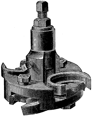
Fig. 3205.
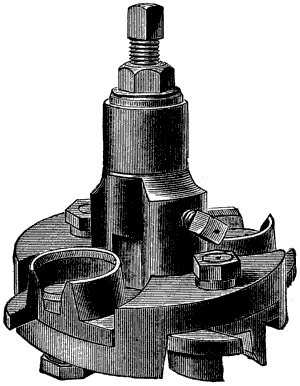
Fig. 3206.
The full amount of cut is taken in successive stages or increments; thus in the figure, the two upper cutters would produce one half the moulding, and the two lower ones the lower half. As the cutters are sharpened by grinding the front face, therefore they will maintain correct shape until they are worn out. Fig. 3205 represents a Shimer head for producing the tongue, and Fig. 3206 a similar head for producing the groove of matched boards.
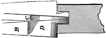
Fig. 3207.
Fig. 3207 shows the action of the groove head, the cutter or bit d being shown in full lines and the second cutter being shown in dotted lines. Cutter d, it will be seen, operates on one half of the groove, and cutter c on the other half, each cutter having side clearance, because of being seated on a seat whose plane is not at a right angle to the axis of revolution of the head.
By thus taking the cut in detail, the head works steadily, while the side clearance makes the cutters cut clean and clear.
JOINTING MACHINE.
“Jointing” a piece of wood or timber, means producing a surface, so that the joint between two pieces that are to come together or be glued shall be close. In order to produce surfaces that shall be true enough for this purpose, it is necessary that the work be held in such a way that it is not sprung or deflected by the holding devices or feeding apparatus.
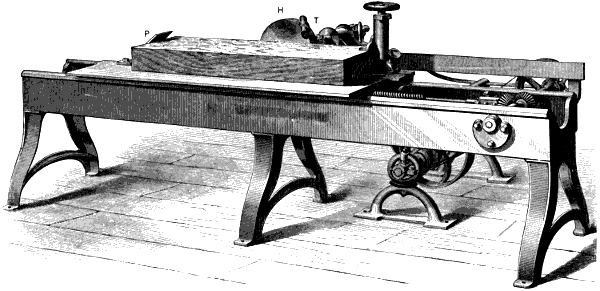
Fig. 3208.
Fig. 3208, for example, represents a jointing machine, in which the work abuts against an inclined plate p at one end, while the other end is clamped down to the table, which is traversed past the revolving head h, to which are secured two gouge-shaped cutting tools, one of which is seen at t. By using tools of this class, the amount of cutting edge in action is small, and will not therefore spring the work, and if the cutter spindle is adjusted to have no end motion, the work will be true, notwithstanding any slight vibration of the head, because its plane of revolution coincides with the plane of the surface being surfaced or jointed.
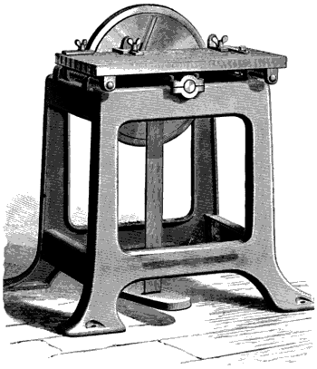
Fig. 3209.
In some jointing machines, knives are set on the face of a revolving disc, an example of this class of machine being shown in Fig. 3209, which is for facing the spokes of wheels and for finishing the mitre joint on them.
Three cutters are used, each being set at an angle to a radial line, so that the inner edge of the knife will meet the work first. This gives the knives a shearing cut, and prevents the whole of the cutting edge from striking the work at once. The spokes are placed against a stop on the table, and brought into contact with the cutters by the foot treadle.
The table has beneath it a spiral spring at each end, which returns the table as soon as the foot pressure is released from the treadle. The cutter head or disc is 10 inches in diameter, and should make 2,000 revolutions per minute.
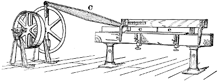
Fig. 3210.
Stroke jointers are machines (such as shown in Fig. 3210) in which a long plane e of the ordinary hand plane type is worked along a slide by a connecting rod c, operated by a crank motion. A machine of this class will do very accurate work, but is obviously suitable for thin work only.
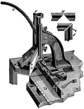
Fig. 3211.
A machine constructed by J. J. Spilker, for cutting mitre joints by hand, is shown in Fig. 3211. The frame a carries a slideway for the slide to which the mitre cutting knife k is secured. The handle g operates a pinion gearing into a rack, which gives vertical motion to the slide and knife. At c is a fence or gauge against which the work is rested, and which is capable of a horizontal motion, so as to bring the work more or less under the knife. For heavy work, the fence c is set back, so that the first cut of the knife will leave the moulding, as shown at h, partly severed, and a second cut is necessary to sever it; for very fine work, a fine shaving may be taken off by a cut taken on the end of each piece separately, after the piece is severed. At d is a graduated scale or rule for cutting the work to exact dimensions, and as its lines are ruled parallel to the right hand edge of the knife k, the inside measurements of a mitre joint may be taken at the outer edge, and outside measurements at the inner end of each line, a set stop at e serving to gauge the pieces for length.
MOULDING OR FRIEZING MACHINES.
These are machines that cut mouldings on the edges of the work. The term friezing is applied by some, when the machine has but one cutter spindle, while by others these machines, whether having one or two spindles, are termed edge moulding machines. Still another term applied to this class of machine is that of variety moulders or variety moulding machines.
In machines of this class, it is of primary importance that lost motion or play in the bearings be avoided, because the cutter end of the spindle overhangs its bearings, and any side play of the spindle in its bearings is multiplied at the cutting edges of the cutters. Perfect lubrication of the spindle bearings, and ample bearing surface on the journals and bearings, are therefore of the first importance.
The work is rested on the upper surface of the table, and is fed to the cutters by hand.
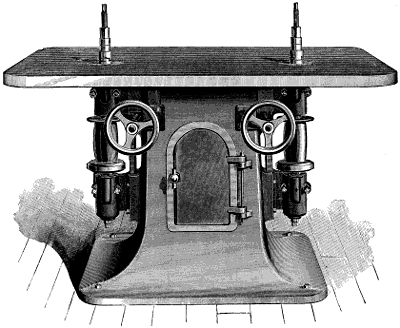
Fig. 3212.
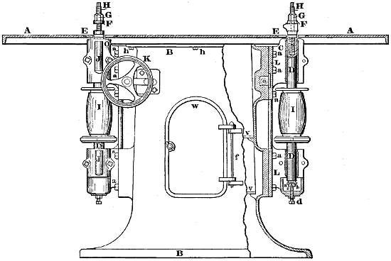
Fig. 3213.
Figs. 3212 to 3215 represent a machine by J. S. Graham. The frame b, b, Fig. 3213, of this machine is cast in one piece cored out, and the base is wide, so as to give necessary solidity. The hollow column is fitted with a door w, and shelves v, v, forming a very complete case for the reception of tools, cutters, etc. The spindle boxes and slides c are one casting. They are planed on centres and held in the frame b′, Fig. 3215, by large gibs l, and sliding surfaces shown in c′, Fig. 3214. They are adjustable vertically by hand wheels k, in front of frame in connection with nut o, as shown in Fig. 3214, and require no lock to hold them at the proper height.
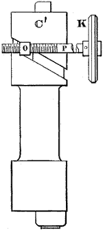
Fig. 3214.
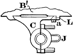
Fig. 3215.
The cap o′ (Fig. 3213) has an oil chamber j and wick which feeds the oil to the upper bearing. The lower box is fitted with a patent self-oiling and adjustable step shown at a, b, c. The cap a, upon which the spindle d rests, has a small opening in the centre. The circular block b, under it, also has a hole in the centre. The bolt d has two holes in it, one horizontal and the other vertical.
The chamber surrounding this step and cup is filled with oil. The motion of the spindle d on the cap a causes the oil to flow from the chamber through the openings to the spindle. Thus the oil is kept in constant circulation. The end of this spindle d is by this arrangement kept always lubricated.
The spindles d are of 17⁄8 hammered tool steel accurately turned and fitted in the boxes, which are of extra length, and lined with the best genuine Babbitt metal. They are 30′′ from centre to centre, and have independent screw tops, as shown at s, enabling the operator to use various sizes for large or small work, or clear the table of either spindle for special work.
h is the threaded part of the screw top, g is the nut, and f the fill-up collars.
The iron table a, a is 5 feet by 4 feet, planed and fitted with concentric rings e, e around the spindle, to suit the various sizes of heads and cutters. A heavy wooden table, made of narrow glued-up strips of hard wood, can be used if preferred.
This machine has been run up to 6,000 revolutions per minute, without perceptible jar, and cutter heads as large as 8′′ diameter may be used on it for heavy work.
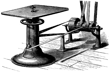
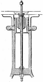
Fig. 3216.
Fig. 3216 represents an edge moulding machine by J. H. Blaisdell. In this machine the table is raised or lowered by the hand wheel upon the central column. The construction of the spindle and its bearings is shown in the sectional view, which also shows the square threaded screw by means of which the table is raised. The spindle has a coned hole for receiving the cutter sockets, which are therefore readily removable.
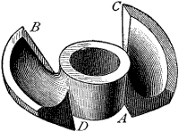
Fig. 3217.
Figs. 3217 to 3220 represent examples of the shapes of cutters for use on edge moulding or friezing machines. Fig. 3217 represents a cutter for bevelling the edge of the work, the cutting edges being at a, b, or at c, d, according to the direction in which the cutter is revolved.
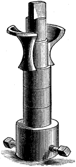
Fig. 3218.
Fig. 3218 represents an ogee cutter, in position on the cutter spindle. As these cutters are made solid and accurately turned in the lathe, they are balanced so long as the cutting edges are kept diametrally opposite. The front faces only being ground to sharpen the cutting edges, the cutter always produces work of the same shape.
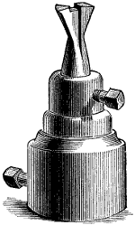
Fig. 3219.
Fig. 3219 represents a cutter (in a chuck) for cutting a dove-tailed groove, and Fig. 3220 one for rounding an edge, it being obvious that a wide range of shapes may be given to such cutters, and that, as they may be sharpened on an emery wheel, they may be left comparatively hard, thus enhancing their durability.
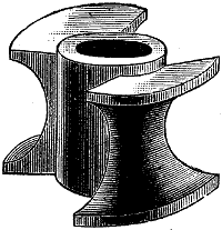
Fig. 3220.
To regulate the depth to which a cutter such as shown in Fig. 3220 will cut, a collar or washer is placed beneath it to act as a guide to the edge of the work.
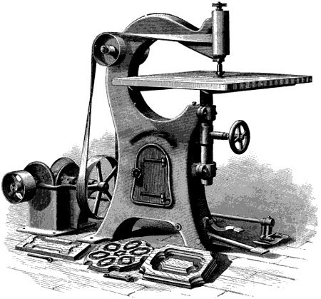
Fig. 3221.
Fig. 3221 represents a machine in which rotary cutters are used to produce all kinds of panel work, as well as edge moulding or friezing. In this case the cutter is above the table, the latter being adjustable for height to suit the thickness of the work. Examples of some of the work are shown at the foot of the machine.
WOOD BORING MACHINES.
The rapidity with which holes may be bored in wood enables the feed to be most expeditiously performed by hand or by foot motion. A foot motion leaves both the workman’s hands free to adjust and change the work, and is therefore suitable for light work or work having holes of a moderate depth.
The work tables of wood boring machines are provided with suitable fences for adjusting the work in position, and in some cases with stops to adjust the depth of hole.
Any of the augers or bits that are used in boring by hand may be used in a boring machine, but it is obvious that, as the bit or auger is forced to its feed by hand or foot, and as its revolution is very rapid, the screw point, which is intended as an aid in feeding when the bit is used by hand, is not necessary. On this account most augers for use in machines are provided with triangular points instead of screw points.
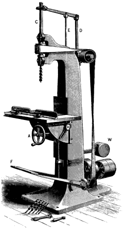
Fig. 3222.
In Fig. 3222 is shown a wood boring machine by J. A. Fay & Co. The table is gibbed to a vertical slide on the face of the column, and is adjustable for height by the hand wheel a, which, through the medium of its shaft and a pair of bevel gears, operates the elevating screw b. The spindle c feeds through its bearings, the supporting rod d being pivoted at its lower end to permit c to feed in a straight line vertically. The feeding is done by the treadle f, which operates the rod e.
The table may be set at an angle of 30 degrees from the horizontal position.
The weight w counterbalances the treadle and brings it to its highest position when the workman’s foot pressure is removed.
The holes may all be gauged to an equal depth (when they are not to pass through the work) by so adjusting the height of the table that the hole is of the required depth when the treadle is depressed to its lowest point, or limit.
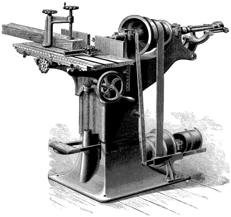
Fig. 3223.
Fig. 3223 represents a horizontal boring machine such as used in furniture and piano factories. The spindle feeds through the driving cone, being operated by the treadle shown. The work table is adjustable for height by the hand wheel and elevating screw. The usual fences, stops, and clamping devices may be applied to the table, which is on compound slides to facilitate the adjustment of the work.
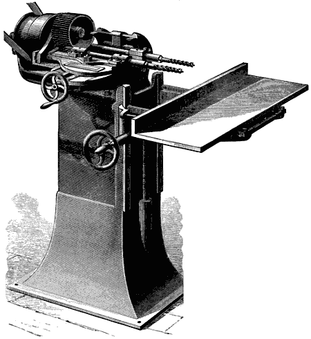
Fig. 3223a.
Fig. 3223a shows a double spindle horizontal boring machine, in which the table and work are fed up to the boring tools by hand. The spindles are adjustable in their widths apart, and may also be set at an angle. The work table is adjustable for height, and the spindle carrying head is adjustable across the machine.
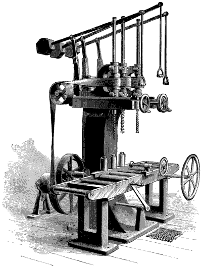
Fig. 3224.
Fig. 3224 represents a machine by J. A. Fay & Co., for heavy work, rollers taking the place of the work table. The drill spindles are fed by hand from the stirrup handles shown, which are weighted to raise up the spindles as soon as they are released.
MORTISING MACHINES.
The mortising machine for wood work consists essentially of an ordinary auger, which bores the holes, and a chisel for cutting the corners so as to produce the square or rectangular mortise that is usually employed in wood work.
The chisel is reciprocated and its driving spindle is provided with means whereby the chisel may be reversed so as to cut on either the sides or the ends of the mortise. The chisel is fed gradually to its cut.
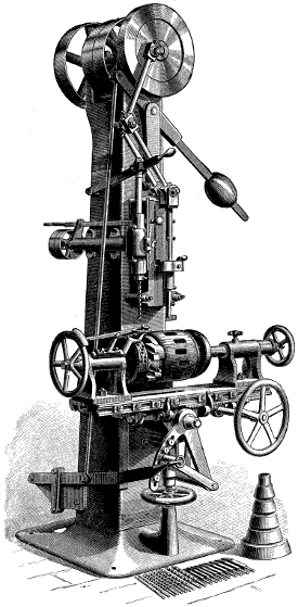
Fig. 3225.
Fig. 3225 represents a mortising machine for the hubs of wheels.
The auger spindle is here fed vertically by a hand lever, the depth bored being regulated by a rod against which the hand lever comes when the hole is bored to the required depth.
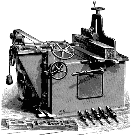
Fig. 3226.
Fig. 3226 represents a mortising machine in which the mortising tool consists of a hollow square chisel containing an auger, and having at its sides openings through which the cuttings escape.
The chisel is rectangular in cross section, but its cutting edges are highest at the corners, as may be clearly seen in the figure.
The work is firmly clamped to the work table and simultaneously to the fence, the upper hand wheel being operated to bring the work-holding clamp down to the work, and the lower one to clamp it so as to press it to both the table and the fence at the same time.
The chisel bar is mounted horizontally in a slide way on a substantial bed that is mounted on a vertical slideway, which enables the chisel bar to be set for height from the work table. It has a horizontal traverse motion or feed, the amount of this motion being governed by the horizontal rod with its nuts and check nuts as shown.
The auger runs continuously, and works slightly in advance of the cutting edge of the chisel, which is passive except when making the mortise.
The chisel bar and auger have a slow, reciprocating motion, and will complete a hole the size of the chisel used. An inch chisel will cut an inch-square hole, consequently a mortise 1′′ × 4′′ would only require four strokes forward to complete it. It has a capacity to work mortises from 3⁄4′′ to 3′′ square, and 5′′ in depth, and any length desired. The boring spindle is driven by an idler pulley, direct from the countershaft.
The bed upon which the timber is placed to be mortised is gibbed to a sliding frame, which allows it to be set to any position, with the chisel straight or at an angle. It is adjustable to and from the chisel bar, to suit the size of material, the under side of which always remains at one height. Adjustments are provided for moving the carriage forward, for regulating the depth of the mortise, the position of the chisel from the face of the material, and the adjustment of the chisel bar, controlling the mortises to be made in the timber.
Two treadles are used upon the side of the machine; the pressure upon one carrying the chisel bar attachment forward, completing the mortise, while the other will instantly force it back when it is desired to withdraw it from the wood, without allowing it to cut its full depth. Provision is made by stops for regulating the length of the stroke as well as the depth of the mortise.
TENONING MACHINES.
In tenoning machines, the lengths of the pieces usually operated upon render it necessary that the work should lie horizontally upon the table, while the shortness of the tenon makes an automatic feed unnecessary.
The revolving heads carrying the cutters in tenoning machines are so constructed that the cutting edges of the cutters are askew to the sides of the heads, but so set as to produce work parallel to the axis of the cutter shaft.
This causes the cutting action to begin at one end of the cutter edge, and pass along it to the other, which enables a steady hand feed, and reduces the amount of power required to feed the work.
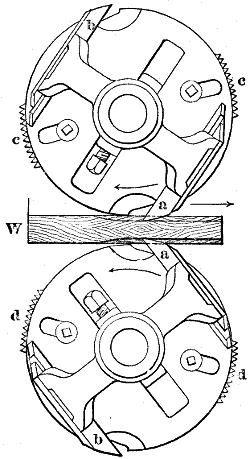
Fig. 3227.
Fig. 3227 represents a cutter head for a tenoning machine, a, a and b, b being the cutters and c, c, d, d spurs which stand a little farther out than the cutter edges, so as to sever the fibre of the wood in advance of the cutter edges coming into action, and thus preserve a sharp shoulder to the tenon, and prevent the splitting out at the shoulder that would otherwise occur.
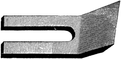
Fig. 3228.
To bring the outer edge of the shoulder in very close contact with the mortised timber, the cutters are for some work followed by what is termed a cope head, which is a head carrying two cutters bent forward as in Fig. 3228, to make them cut very keenly, as is necessary in cutting the end grain of wood.
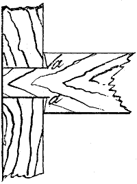
Fig. 3229.
The cope head undercuts the shoulder, as shown at a, a, in Fig. 3229, which is a sectional view of a mortise and tenon.
Large
image
(263 kB).
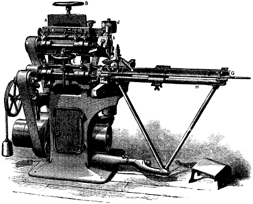
Fig. 3230.
Fig. 3230 represents a tenoning machine for heavy work, constructed by J. A. Fay & Co., adjusted for cutting a double tenon, the upper and lower heads revolving in a vertical plane, and the middle head in a horizontal plane.
a is a vertical slideway for the heads c, d, carrying the shafts for the cutter heads a, b. At b is the hand wheel for adjusting d, and at e that for adjusting c. The pulley d is for driving the cope heads, one of whose cutters is seen at c. The work carriage h is provided with rollers which run on the slide on k, and is supported by the arm i, which rises and falls to suit the cross motion of h. The fence g, for the work, is adjustable by means of the thumb nuts.
SAND-PAPERING MACHINES.
Sand-papering machines are of comparatively recent introduction in wood working establishments, but are found very efficient in finishing surfaces that were formerly finished by hand labor.
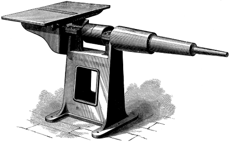
Fig. 3231.
Fig. 3231 represents a sand-papering machine, by P. Pryibil, in which a spindle has three stepped cones on one end, and a parallel roller or cylinder at the other. The steps on the spindle are covered with a rubber sleeve, and the sand paper is cut to a template, and the edges brought together and joined by gluing a strip of tough paper under them. When this has become dry the paper is slightly dampened everywhere except at the joint, and is then slipped on the taper drums. In drying it shrinks and becomes tight and smooth upon the rubber covering with which the drums are provided. These are of different sizes to fit different curves in the work.
Flat work is done upon the table, which is hinged and provided with an adjusting screw to regulate its height, and it can be raised to give access to the drum.
When sand paper is applied in this way, every grain is brought into contact with the work, whereas at first only the larger grains cut when it is used on the faces of revolving discs, as in some machines of this class. Furthermore, when used on drums it is offered ample opportunity to clear itself of dust; it therefore does not become clogged, and, as a consequence, it lasts longer and does more and better work than when used on discs.
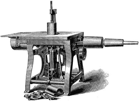
Fig. 3232.
Fig. 3232 represents a similar machine, but having a spindle vertical also, so that one face of the work can be laid on the table, which acts as a guide to keep the work square, the table surface being at a right angle to the vertical spindle.
The vertical cylinder or drum is split on one side, and provided with internal cones, so, that by screwing down the nut shown the drum can be expanded to tightly grip the sand paper, which is glued and put on as already described.
Besides these rotary motions, these drums receive a slow vertical motion, the amount of which is variable at the operator’s pleasure. This provides for using the full face of the drum on narrow work, while it prevents the formation of ridges or grooves in the work.
For sand-papering true flat surfaces the flat table is provided, there being beneath it a parallel revolving drum, whose perimeter just protrudes through the upper surface of the table. The surface of the table thus serves as a guide to steady the work while the sand-papering is proceeding.
By using sand paper in this manner, every grain of the sand is brought into contact with the work; furthermore, a small area of sand paper is brought into contact with the work, and the wood fibre can fly off and not lodge in the sand paper; while at the same time the angles of the grains of sand or glass are presented more acutely to the work, and therefore cut more freely and easily. Hence the sand paper lasts much longer, because a given pressure is less liable to detach the sand from the paper.
The machine is constructed entirely of iron, and the drum is intended to revolve at about 800 revolutions per minute.
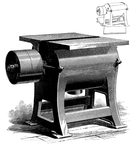
Fig. 3233.
Fig. 3233 represents a sand-papering machine in which a long parallel cylinder is employed, the work resting on the surface of the table and being fed by hand. In using a machine of this class the work should be distributed as evenly as possible along all parts of cylinder, or one end of the cylinder may become worn out while the other is yet sharp; this would incapacitate the machine for wide work unless a new covering of sand paper were applied.
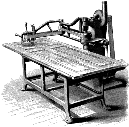
Fig. 3234.
Fig. 3234 represents a sand-papering machine constructed by J. A. Fay & Co., for finishing doors and similar work. The frame constitutes a universal joint enabling the sand paper disc to be moved anywhere about the door by hand. An exhaust fan on the top of the main column removes the dust from the work surface. The head carrying the disc is moved vertically in a slideway to suit different thicknesses of work.
VOL. II. SANDING MACHINES. Plate XXVII.
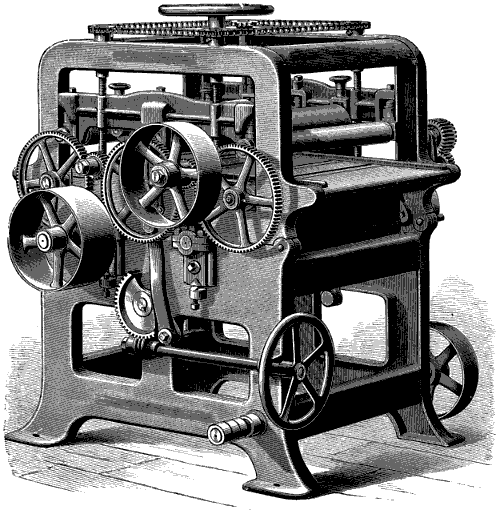
Fig. 3235.
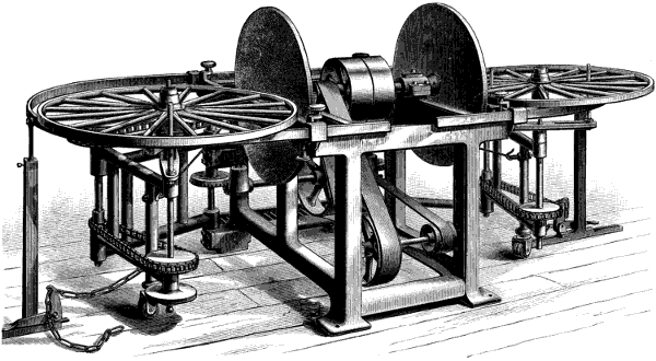
Fig. 3236.
Fig. 3235 represents a self-feeding sand-papering machine constructed by J. A. Fay & Co. It is made in three sizes, to work material either 24′′, 30′′, or 36′′ wide by 4′′ thick and under; it has a powerful and continuous feed, and gives to the lumber a perfect surface by once passing it through the machine.
The feeding mechanism consists of six rollers, in three pairs, driven by a strong train of gearing. The upper feeding rollers, with the pressure rollers over the drum are lifted together in a perfect plane by the movement of four raising screws, operated by a chain and hand wheel. The lower feeding rollers always remain in perfect line with the drums.
It is supplied with two polishing cylinders, placed in the body of the machine, on which the upper frame rests, both having a vibratory lateral motion for removing lines made by irregularities in the sand paper. The finishing cylinder is placed so that the discharging rollers carry the lumber from it, thus running through and finishing one board, if desired, without another following, and these rollers are arranged for a vertical adjustment to suit the dressed reduction on the material to be worked. The roughing cylinder carries a coarse grade of sand paper, and the finishing one a finer grade. They may be driven in opposite or in the same direction, as may be necessary. The lower frame is hinged at each end to the upper frame, so that by removing a pin, either cylinder can be reached by raising the frame with the screw and worm gear, operated by a hand wheel at the end of the machine.
A brush attachment (not shown in the cut) is now placed at the end of the machine just beyond the finishing cylinder, which is a most complete device for brushing the material clean after it leaves the sand-papering cylinders.
Fig. 3236 represents a double wheel sanding machine by J. A. Fay & Co.
This machine is intended for accurately finishing the tread of the wheel ready for the tire, and is one of the most useful and labor-saving machines that can be placed in a wheel shop.
The frame is built entirely of iron, and has a heavy steel arbor running in long bearings, with tight and loose pulleys in the centre. On each end of the arbor is a large sand paper disc for polishing the tread of the rim.
The wheel to be finished is laid on a rotating carrying frame, having two upright drivers. These are attached to a jointed swinging frame, with flexible connections, adjustable to suit wheels of varying diameters.
The first section of the jointed frame is driven by a shaft and bevel gears, and swings upon it. The second one has the wheel-carrying frame, and swings upon the extreme end of the first one, and is driven from it by a chain connection.
A roller wheel is secured at the bottom of the leg, affording a floor support; also a chain to regulate the proper distance of the wheel from the discs.
A wrought iron supporting frame is attached upon each side of the sand paper discs, adjustable for different sizes.
The wheel when placed in the machine is carried by the gearing against the sand paper discs, which finishes the tread in the most accurate and perfect manner.
Machines are made both single and double. The latter are the most desirable, as the operator has only to place a wheel in position on one side, when it feeds and takes care of itself.
By the time this is done, the wheel on the opposite side will be finished and ready to be removed, when a fresh one is put in, and the operation continued, the only care required being to put in and remove them. Its capacity is 150 set of wheels per day, and it will do the work better than can be done by hand.