Volume 2 — Chapter XXV.—VICE WORK. (continued 2)
Reading edition
Again, the line marked 1 measures 13⁄16 inch from c, because it requires a chisel edge 13⁄16 deep to cut a moulding that is one inch deep. But if we measure from c to the line marked 2 we find that it is 21⁄4 inches from c, and since it represents a chisel that will cut a moulding two inches deep, we observe that the deeper the moulding is the nearer the depth of cutting edge is to the depth of moulding it will produce. This occurs because the longer the chisel the more nearly it stands parallel to the line a, at the time when its point is crossing the line a. Thus, line i is more nearly parallel to a than line a is, and our scale has taken this into account, for it has no two lines equally spaced; thus, while that marked 1⁄4 is 5⁄16 inch distant from c, that marked 1⁄2 is less than 5⁄16 inch distant from that marked 1⁄4, and this continues so that the line marked 2 is but very little more than 1⁄4 inch from that marked 13⁄4. Having constructed such a scale we may rub out the circle, the arcs, the line a, and all the lines except the line from c to a and its graduations, and we have a permanent scale for any kind of moulding that can be brought to us.
If, for example, the moulding has the four steps or members s, t, u, v, in the figure, each 1⁄2 inch deep, then we get the depth of cutter edge for the first member s on our scale, by measuring from c to the line 1⁄2 on line c a. Now the next member t extends from 1⁄2 to 1 on the moulding, and we get length of cutter edge necessary to produce it from 1⁄2 to 1 on the scale. Member u on the moulding extends from 1 to 13⁄4; that is to say, its highest point is 1 inch and its lowest 13⁄4 inch from the top of the moulding, and we get the length for this member on a scale from the 1 to the 13⁄4; and so on for any number of members.
After the depth of cutting edge for each member has thus been found, it remains to find the exact curve of cutting edge for each step, and, in doing this, the same scale may be used, saving much labor in this part also of the process, especially where a new piece of moulding must be inserted to repair part of an old piece that needs renewal in places only, as is often the case in railroad cars.
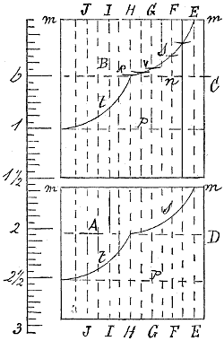
Fig. 2197a.
In Fig. 2197a we have a scale or rule constructed upon the foregoing principles, but marked to sixteenths, and it may now be shown that the same scale may be used in finding the actual curve as well as the depth of cutter edge necessary to produce the moulding of any member of it. Let the lower curves s, t, for example, represent the moulding to be produced, and the upper outline represent the blank piece of steel of which the cutter is to be made, the edges c, d being placed in line one with the other. We may then draw across both the moulding and the steel, lines such as e e, f f, g g, h h, i i, j j, all these lines being parallel to the edges c, d. To get the total depth of cutter edge for the moulding we measure with a common measuring rule the total height of the moulding, and supposing it to measure an inch, we set a pair of compasses to an inch on our cutter scale, and with them mark from the base m of the steel, the line p giving total depth of cutter edge. We next measure with a common rule the depth of member s of the moulding, and as it measures 1⁄2 inch we set the compasses to the 1⁄2 on the cutter scale, and with these compasses mark from line m line b, showing the depth of member s. In order to find the exact curve for each member, we have first to find a number of points in the curve and then mark in the curve by hand, and it is for the purpose of finding these points that the lines e e, f f, g g, h h, i i, j j, have been drawn. These lines, it may be remembered, need not be equally spaced, but they must be parallel, and as many of them may be used as convenient, because the greater their number the more correctly the curve can be drawn.
The upper edge or base line, m m, both of the steel and of the drawing, is that from which all measurements are to be taken in finding the points in the curve, which is done as follows: With an ordinary measuring rule we measure on the moulding and from line m m of the moulding as a base the length of the line f f below m m, to the curve, which in this case measures say 5⁄16 inch; we then set a pair of compasses or compass calipers to the 5⁄16 on the cutter scale, and from base m m on the cutter steel, mark, on line f f, an arc, and where the arc cuts f f is one point in the curve.
Similarly we measure on the moulding, or drawing of the moulding, the length of line g g from line m m to the moulding curve, and find that it measures, say 7⁄16 inch, hence we mark from base line m m of the steel, on line g g, arc v, distant 7⁄16 according to the cutter scale. Similar measurements are taken at each vertical line of the drawing which represents the moulding, and by means of the corresponding divisions of the cutter scale, arcs are marked on the vertical lines on the cutter steel, and where the arcs cut the vertical lines are points in the curve, and through these points the curve may be drawn by hand. We may make a cutter scale from an ordinary parallel rule, marking one end to correct inches and the other end for a cutter scale. Measurements from the moulding may then be made on one end of the rule; measurements for the cutter may be taken from the other end of the rule, and the rule may be used at the same time to draw the parallel lines e e, &c. Or, as each size of cutter head requires a different cutter scale, we may make a rule out of a piece of box or other close-grained wood, say 3⁄4 inch square, using one side for each size of cutter head. One end of each face of this rule may be marked in correct inches and parts of an inch (the divisions being thirty-seconds of an inch), and the other end may be marked as a cutter scale, the divisions being found as described with reference to Fig. 2197.
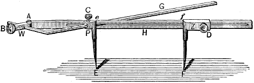
Fig. 2198.
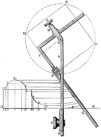
Fig. 2199.
An instrument, patented by R. Drummond, for finding the depth of cutting edge and also for finding the curves, is shown in Figs. 2198 and 2199. It consists essentially of a bar g bent at a right angle, thus making two arms. Upon one arm is a slide w (best seen in Fig. 2199) secured by a set-screw b, and having at a a pivot to carry a second bar h, which is slotted throughout its length to permit bar g to slide freely through it. Upon the other arm of g is a slide p secured by a set-screw c, and carrying a compass point e. The bar h carries an adjustable slide z secured by a set-screw d and carrying the compass point f.
Fig. 2200.
In using the instrument but three very simple operations are necessary. First, the two slides w and p are set to the numerals on the bar, which correspond to the size of the head on the moulding machine the cutter is to be used upon; thus in Fig. 2199 they are shown set to numeral 2, as they would be for a 2-inch cutter head. The instrument is next opened, its two bars occupying the position shown in Fig. 2199, and the two compass points are set to the height of the moulding or to any desired member of it, as the case may be. The bars are then opened out into the position shown in Fig. 2200, and the compass points at once give the depth of cutter edge necessary to produce the required depth of moulding.
It will be noted that the pivot a represents the centre upon which the cutter revolves, and that while the face of the bar h corresponds to the line of moulding formation answering to line a a in Fig. 2196, the face of bar g corresponds to the face c f of the cutter in Fig. 2196; hence the instrument simply represents a skeleton head and cutter, having motions corresponding to those of an actual cutter head and cutter.
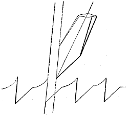
Fig. 2201.
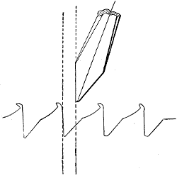
Fig. 2202.
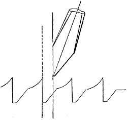
Fig. 2203.
The File.—The file is a piece of hardened steel having teeth produced upon its surface by means of rows of chisel cuts which run more or less diagonally across its width at an angle that is varied to suit the nature of the material the file is to be used upon. The vertical inclination of the tooth depends upon the inclination of the face of the chisel with which it is cut, the two being equal, as is shown in Fig. 2201, which is an enlarged view of a chisel and some file teeth. In order that the tops of the teeth shall be sharp, and not rounded or curved, as in Fig. 2202, it is necessary that the edge of the chisel be kept sharp, an end that is greatly aided by the improved form of chisel shown in Fig. 2203. When a file possesses curved points, or caps, as they are technically termed, a few strokes upon a narrow surface will cause them to break off, reducing the depth of the teeth and causing the cuttings to clog in them. If, however, the file is used upon a broad surface these caps will remain, obviously impairing the cutting qualifications of the file, even when new, and as they soon get dulled the file loses its grip upon the work and becomes comparatively valueless.
Files were, until the past few years, cut entirely by hand—file cutting by machinery having previously been a wide field of mechanical experiment and failure. Among the most prominent causes of failure was that the teeth produced by the earlier machines were cut too regular, both as to their spacing and their height; hence the points of the rear teeth fell into the same channels as those in advance of them, thus giving the tooth points too little opportunity to grip the work. This also gives too broad a length of cutting edge and causes the file to vibrate on the forward or cutting stroke, an action that is technically known as chattering, and that obviously impairs its cutting capacity. The greatest amount of duty is obtained from a file when the rear tooth cuts off the projection left by the preceding one, because in that case the duty of the tooth is confined to cutting off a projection that is already weakened and partly separated from the main body by having the metal cut away around its base. Workmen always practically recognise this fact, and cause the file marks to cross each other after every few strokes. In the machine-cut files made by The Nicholson File Co., the teeth are arranged to attain this object by the following means:—1. The rows of teeth are spaced progressively wider apart from the point towards the middle of the file length by regular increments of spacing, and progressively narrower from the middle toward the heel. 2. This general law of the spacing is modified by introducing as the teeth are cut an element of controllable irregularity in the spacing, which irregularity is confined within certain limits, so that neither the increment nor decrement of spacing is entirely regular. 3. In arranging the teeth so that the successive rows shall not be exactly parallel one to the other, the angle of inclination being reversed as necessity requires. The irregularity of spacing, while sufficient to accomplish the intended object, is not enough to practically vary the cut of the file, or, in other words, it is insufficient to vary its degree of coarseness or fineness to any observable extent. But it enables the file to grip the work with as little pressure as possible, and enables the teeth to cut easily without producing deep file marks or furrows.
Files and rasps have three distinguishing features: 1. Their length, which is always measured exclusively of their tangs. 2. Their cut, which relates not only to the character, but also to the relative degree of coarseness of the teeth. 3. Their kind or name, which has reference to the shape or style. In general, the length of files bears no fixed proportion to either their width or thickness, even though of the same kind. The tang is the spiked-shaped portion of the file prepared for the reception of a handle, and in size and shape should always be proportioned to the size of the file and to the work to be performed. The heel is that part of the file to which the tang is affixed.
Of the cut of files we may say that it consists of three distinct forms; viz.: “single cut,” “double cut” and “rasp,” which have different degrees of coarseness, designated by terms as follows viz.:—
Single-cut. Double-cut. Rasp.
Rough Coarse Coarse
Coarse Bastard Bastard
Bastard Second-cut Second-cut
Second-cut Smooth Smooth
Smooth Dead-smooth
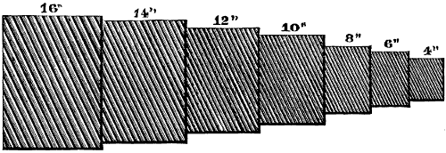
Fig. 2204.
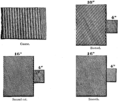
Fig. 2205.
The terms “rough,” “coarse,” “bastard,” “second-cut,” “smooth” and “dead-smooth,” have reference only to the coarseness of the teeth, while the terms “single-cut,” “double-cut” and “rasp” have special reference to the character of the teeth. The single-cut files (the coarser grades of which are sometimes called “floats”) are those in which the teeth are unbroken, the blanks having had a single course of chisel-cuts across their surface, arranged parallel to each other, but with a horizontal obliquity to the central line, varying from 5° to 20° in different files, according to requirements. Its several gradations of coarseness are designated by the terms “rough,” “coarse,” “bastard,” “second-cut” and “smooth.” The rough and coarse are adapted to files used upon soft metals, as lead, pewter, &c., and, to some extent, upon wood. The bastard and second-cut are applied principally upon files used to sharpen the thin edges of saw teeth, which from their nature are very destructive to the delicate points of double-cut files. The smooth is seldom applied upon other than the round files and the backs of the half-rounds. Fig. 2204 represents the cut of single-cut rough files, their lengths ranging from 16 inches down to 4 inches. Fig. 2205 shows the cut of the coarse, bastard, and second-cut, whose lengths also range from 16 to 4 inches, and whose cut is also finer as the length decreases. The float is used to some extent upon bone, horn, and ivory, but principally by plumbers and workers in lead, pewter, and similar soft metals. It will be seen that the teeth are nearly straight across the file and are very open, both of these features being essential requirements for files to be used on the above-named metals.
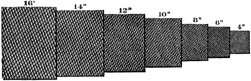
Fig. 2206.
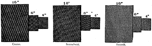
Fig. 2207.
Double-cut files are those having two courses of chisel cuts crossing each other. The first course is called the over cut, and has a horizontal obliquity with the central line of the file, ranging from 35° to 55°. The second course, which crosses the first, and in most double cuts is finer, is called the up-cut, and has a horizontal obliquity varying from 5° to 15°. These two courses fill the surface of the file with teeth inclined toward its point, the points of which resemble somewhat, when magnified, those of the diamond-shaped cutting tools in general use. This form of cut is made in several gradations of coarseness, which are designated by the terms “coarse,” “bastard,” “second-cut,” “smooth” and “dead-smooth.” Fig. 2206 represents the cut of double-cut bastard files, from the 16 inch down to the 4 inch, and Fig. 2207 the cut of the coarse, second-cut, and smooth. For very fine finishing a still finer cut, called the dead-smooth, is made, being like the smooth, but considerably finer. It is a superior file for finishing work in the lathe, or for draw-filing machine work that is to be highly finished. The double-cut is applied to most of the files used by the machinist, and, in fact, to most of the larger number in general use. For unusually fine work, tool-makers and watch-makers use the Swiss or Groubet files—so called from their being made by M. Groubet, of Switzerland. These files are double-cut, and their degree of coarseness is denoted by number; thus, the coarsest is a bastard and the finest number 8. The prominent characteristics of these files are their exceedingly even curvature and straightness, and, in the finer grades, the unusual fineness of the cut, which feels soft and velvety to the touch. They are made in sizes ranging from 2 to 10 inches, and are always double-cut.
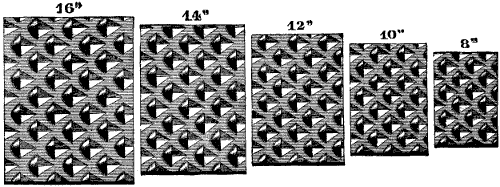
Fig. 2208.
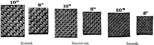
Fig. 2209.
Rasps differ from the single or double-cut files in that the teeth are disconnected from each other, each tooth being made by a single-pointed tool, denominated by file-makers a punch, the essential requirement being that the teeth thus formed shall be so irregularly intermingled as to produce, when put in use, the smoothest possible work consistent with the number of teeth contained in the surface of the rasp. Rasps, like files, have different degrees of coarseness, designated as “coarse,” “bastard,” “second-cut” and “smooth.” The character and general coarseness of these cuts, as found in the different sizes, are shown in Figs. 2208 and 2209. Generally speaking, the coarse teeth are applied to rasps used by horseshoers, the bastard to those used by carriage makers and wheelwrights, the second-cut to shoe-rasps, and the smooth to the rasps used by cabinet-makers.
Figs. 2210, 2211 and 2212 are respectively coarse, bastard, and finishing second-cut files, the first two being for brass.
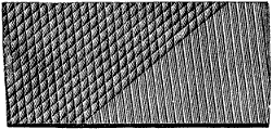
Fig. 2210.
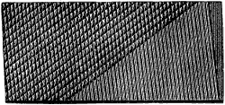
Fig. 2211.
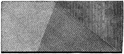
Fig. 2212.
Fig. 2210 represents a file open in both its over and up-cut, which is not, therefore, expected to file fine, but fast, and is adapted for very rough work on the softer metals, as in filing off sprues from brass and bronze castings, filing the ends of rods, and work of a similar nature. It is also, to some extent, used upon wood. The essential difference between the bastard file shown in Fig. 2211 and that just described is the degree of fineness of the up-cut, which is nearly straight across the tool. This form of teeth, which may be applied to any of the finer cuts, and upon any of the shapes usually made double-cut, is especially adapted to finishing brass, bronze, copper and similar soft metals, and is not so well adapted to the rougher work upon these metals as the coarse brass file previously described. Fig. 2212 is a finishing file. The first or over-cut in this case is very fine, and, contrary to the general rule, has the least obliquity, while the up-cut has an unusual obliquity, and is the coarser of the two cuts. The advantages in this arrangement of the teeth are that the file will finish finer, and by freeing itself from the filings is less liable to clog or pin than files cut for general use. This form of cut is especially useful when a considerable quantity of finishing of a light nature is required upon steel or iron. It is not recommended for brass or the softer metals, nor should it be made of a coarser grade than the second-cut.
The names of files are sometimes derived from the purpose for which they are to be used. Thus, we have saw files, slitting files, warding files, and cotter files. The term “warding” implies that the file is suitable for use on the wards of keys, while “cotter” implies that it is suitable for filing the slots for that class of key which the machinist terms a cotter. In other cases files are named from their sections, as in the case of “square,” “round,” “half-round,” and “triangular,” or “three-square” files, as they are often termed.

Fig. 2213.
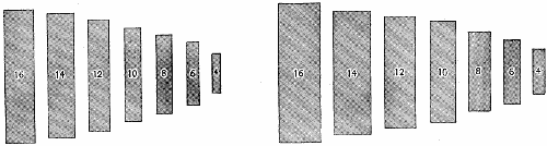
Fig. 2214.
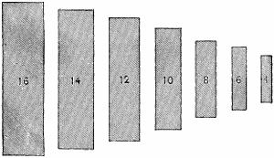
Fig. 2215.
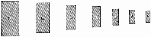
Fig. 2216.

Fig. 2217.
The term “flat” may be considered strictly as meaning any file of rectangular section whose width exceeds the thickness. Hence, “mill files,” “hand files,” and “pillar files” all come under the head of flat files, although each has its own distinguishing features. The general form of the flat file is shown in Fig. 2213, while the cross-sections of various quadrangular files are shown in Figs. from 2214 to 2218. From these views it will be seen that the thicknesses gradually increase from the mill to the square file. Mill files are slightly tapered from the middle to the point both in their width and thickness. They are single-cut, and are usually either bastard or second-cut, although they are sometimes double-cut. Mill files of both cuts are principally used for sharpening mill saws, mowing-machine knives and ploughs, and in some machine shops for rough lathe work, and, to some extent, in finishing composition brasswork. Mill sections are occasionally made blunt—that is to say, their sectional shape is alike from end to end—in which case they are mostly double-cut, and seldom less than 8 inches in length. They are suitable for filing out keyways, mortises, &c., and for these purposes should have at least one safe edge. A safe edge is one having no teeth upon it, which allows the file to be used in a corner without cutting more than one of the work surfaces. When the corner requires to be very sharp it is preferable to take a file that has teeth upon its edge and grind the teeth off, so as to bring the corner of the file up sharp, which it will not be from the cutting, because the teeth do not come fully up to a sharp corner.
Hand-files are tapered in thickness from their middle towards both the point and the tang, and are, therefore, well curved or bellied on each side. This fits them for the most accurate of work, on which account they are generally preferred by expert workmen. They are nearly parallel in width and have one safe edge and one edge cut single, while the face is cut double. Hand-files are also made equaling, the term equaling meaning that, although apparently blunt or of even thickness throughout the length, yet, in fact, there is a slight curvature, due to the file being thickest in the middle of its length. An equaling hand-file is especially suitable for such purposes as filing out long keyways, in which a great part of the file length is in action, and it can, therefore, be easily pushed in a straight line.
The flat file, Fig. 2213, when 10 inches and under in length, is made taper on both its sides and edges, from the middle to the front of the file, and when longer than 10 inches they should be made full taper—that is to say, the taper should extend from the middle toward the heel, as well as toward the point. Flat files are usually double-cut, the coarse-cut being used upon leather, wood, and the soft metals. The flat bastard is that most commonly used, the flat second-cut, smooth, and dead-smooth being used by machinists for finishing purposes, the latter preceding the polishing processes.
Pillar files are tapered in thickness from the middle to each end; the width is nearly parallel, and one of the edges is left safe. They are double-cut, and, although not in general use, are especially adapted to narrow work, such as in making rifles, locks, &c. The square file ranges from 3 to 16 inches in length, and is made for general purposes with considerable taper. It is usually double-cut, the bastard being the principal cut, the second-cut and smooth being mainly used by the machinist.
Square blunt files range from 10 to 20 inches in length, of the same sectional sizes as the square taper, and are cut double, usually bastard. For machinists’ use, however, they are used in the second-cut also, and are provided with sometimes one and sometimes two safe sides. Square equalling files are in every respect like the square blunt, except in the care taken to prepare a slight curve or belly in the length of the file, which greatly enhances their value in filing out the edges of keyways, splines, or mortises. The fault of the square blunt, when used for fine, or true work, is that the heel, having no belly, is apt to come into too prominent action.
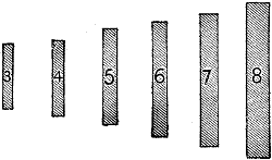
Fig. 2218.
Warding files, Fig. 2218, are made parallel in thickness, but are considerably tapered on their edges. They range in size from 3 to 8 inches in length, progressing by half-inches in the sizes below 6 inches. They are cut double, and usually on both edges, and are mainly used by locksmiths and jewellers, and to but a limited extent by machinists. Some of the warding files are provided with teeth upon their edges only, which are made quite rounding, the cut usually being second-cut, single.
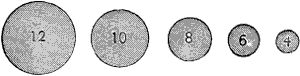
Fig. 2219.
Files deriving their sections from the circle are shown from Figs. 2219 to 2222. “Round files” are circular in section, as shown in Fig. 2219, their lengths ranging from 2 to 16 inches, and are usually of considerable taper. The small bastards are mostly single-cut and the larger sizes double-cut. The second-cuts and smooths are rarely double-cut, except in some of the very large sizes. In imitation of double-cut, however, they are sometimes made with the first, or overcut, very open, called “hopped,” which adds, however, but very little to the cutting capacity of the file. The very small sizes—as, say, those of one-quarter inch and less in diameter—are often called “rat-tailed” files. For some classes of work—as for instance, the circular edges of deep keyways—round, blunt files are used, their sizes running up to 18 and 20 inches, their principal cut being bastard and double.
The gulleting file is a round, blunt saw file, and, like most other files for this purpose, is single-cut (except for a small space at the point, which is left uncut). Its principal use is for extending the gullet of what are known as gullet-tooth and briar-toothed saws.
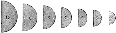
Fig. 2220.
Half-round files are of the cross-section shown in Fig. 2220, and although their name implies a semicircle, yet, as generally made, their curvature does not exceed the third part of a circle. They are made taper; the bastard is usually double cut on both its sides; the second-cut and smooth is double-cut on their flat sides, and single-cut on the curve side, except occasionally in the larger sizes, when it is double-cut or hopped. Half-round files for wood usually range in size from 10 to 14 inches, and are of the same shape and taper as the regular half-rounds. They are cut coarse and double, and are used by wood-workers generally. Half-round rasps are also like the regular half-round in shape, the sizes usually called for being 10, 12, and 14-inch. They are used principally by wheelwrights and carriage builders, but are to some extent used by plumbers and marble workers.
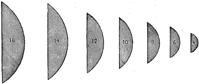
Fig. 2221.
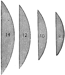
Fig. 2222.
Cabinet files are of the section shown in Fig. 2222, being both wider and thinner than the half-rounds, the sectional curvature being somewhat less than the fifth part of a circle. They are made taper from near the middle to the point, while both the files and the rasps are made from 6 to 14 inches in length; 8, 10, and 12 inches are the sizes in most common use. As usually known, the cabinet file is a bastard double-cut. The cabinet rasp is punched smooth, and both the cabinet rasp and file are rarely made of any other degree of coarseness. They are used by cabinet, saddle-tree, pattern, and shoe-last makers, and also by gunstockers and wood-workers generally.
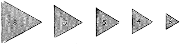
Fig. 2223.
Three-square files are made with equilateral triangular sections, as in Fig. 2223. They are tapered to a small point with considerable curve, and are double-cut. The larger sizes—say, from 10 to 14 inches—are usually bastard, and are used to a considerable extent in rolling mills. The smaller sizes are not unfrequently smooth or dead-smooth, and are used in machine shops quite generally for filing interval angles more acute than the rectangle, clearing out square corners, sharpening cutters, &c. Three-square blued files of sizes from 3 to 6 inches are sometimes made. They are mostly second-cut, or smooth and double-cut, and are principally used in machine shops for filing up cutters for working metals.
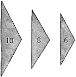
Fig. 2224.
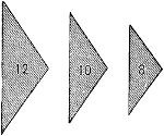
Fig. 2225.
Cant files, whose cross-sections are shown in Fig. 2224, are usually made blunt and double-cut, mostly bastard, on all three sides. These sizes are usually 6, 8, and 10 inches. Lightning files are of the cross-section shown in Fig. 2225, the term lightning being known principally by those using the saws of this name, and to some extent by those using other cross-cut, M-shaped saw teeth. The obtuse angle of this file is five-canted, while the regular cant is hexagon or six-canted, and it is found to be too obtuse for the purposes required of the saw file. They are made blunt, and range in length from 4 to 12 inches, and are cut (except for a short space near the point) single on their three sides.
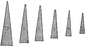
Fig. 2226.
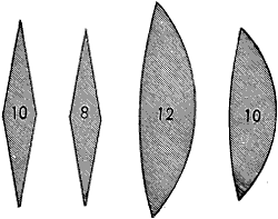
Fig. 2227.
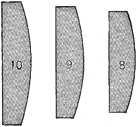
Fig. 2228.
Knife files are of the section shown in Fig. 2226, and rarely exceed 10 inches in length, the principal sizes being 4, 5, and 6-inch. They are tapered, resembling somewhat the blade of a knife, and are cut double. The very acute angle of the sides of this file makes it especially useful in filing the inner angles of the rear and main springs of a rifle lock and work of similar shape. These files are also made blunt. Cross files (sometimes called double half-round or crossing files) are of the section shown in Fig. 2227. They are mostly made to order, either blunt or tapered, and usually double-cut. “Feather-edge” files (Fig. 2227) are but little used by the mechanics of this day. They were formerly used in filing feather springs (as the rear spring of a gun lock is sometimes called), and also the niches in currycombs, which led them to be called by some currycomb files. The few files of this kind which are now made are usually blunt and double-cut. Half-round “shoe rasps” as generally made are of the cross-section shown in Fig. 2228, their sizes ranging from 6 to 12 inches, while 8, 9, and 10 inch are the most common. They are made parallel in width, but with their sides slightly tapered from the middle; the ends are rounded and cut single; the edges are safe or uncut, or if cut are usually made half-file and half-rasp reversed (1⁄4 rasp and 3⁄4 file, while sometimes made, are the exception). The file quarters are bastard double-cut, and the rasp quarters second-cut. This form of shoe rasp is the one in general use at this time, having almost entirely superseded the flat and swaged rasps formerly in use.
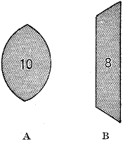
Fig. 2229.
Reaper files (b, Fig. 2229), so called from their use in sharpening the knives of reaping and mowing machines, are of the cross-section shown. They range in length from 7 to 10 inches, are slightly tapered, and are cut single and on their sides only.
Tumbler files, whose cross-section is shown at a, Fig. 2229, were formerly much used to file the tumblers of gun locks, but are now rarely called for. They are taper and cut double. It will be seen, however, that unless for some special purpose, the pitsaw round or half-round file will be found to answer the same purpose as the tumbler file.
It is obvious that in the use of files the coarser cuts are for use when it is required to remove a maximum quantity of material, and the finer to produce a more smooth and true surface, and also that the form of file selected is that which will best conform to the shape of the work, or can be best admitted upon or into the work.
In selecting the length of the file, the size of the work and the delicacy of the same are the determining considerations; thus, a 14-inch file would be a clumsy tool upon a small piece of work, as, say, one having an area of 1⁄2 inch square. In selecting the shape of the file there are, however, other considerations than the shape of the work. Among these considerations may be enumerated that, in proportion as the number of teeth on any given file, performing cutting duty simultaneously, is increased, the less metal will be taken off, because the pressure on each tooth is reduced, and the file does not bite or take hold of the work so well; hence it cuts smoother.
To fit the handles to small files, as 6-inch or less, it is simply necessary to bore suitable-sized holes in the handles, and force in the tang of the file. In doing this care should be taken to bore the hole axially true with the handle, so that the latter may stand true with the file, which greatly assists the production of true and rapid filing.
For larger files the handle should have a small hole bored up it as before, the file tang should be made red hot (a piece of wet rag or cotton waste being wrapped around the heel of the file, so that it shall not get hot and be softened), and forced into the handle by hand, the file and handle being rotated during the operation, and sighted to insure that the handle is kept true with the centre line of the file. So soon as the tang of the file has entered three-quarters or thereabouts of its length it should be removed and gradually cooled by dipping in water.
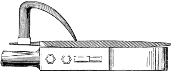
Fig. 2230.
When the surface of the work is so large that the file handle would meet the work before the point had reached fully across it, the raised handle shown in Fig. 2230 is employed. The square end of the handle has a dovetail groove into which the tang of the file is fitted. In the figure the file is shown applied to a connecting rod end, and in such broad surfaces it is especially necessary to vary the line of motion of the file after every few strokes, so as to cause the file marks to cross and recross, as shown in Fig. 2231.
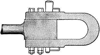
Fig. 2231.
The height at which work should be held to file it to the best advantage depends entirely upon its size, the amount of metal to be filed off, and the precision to which the filing requires to be executed.
Under ordinary conditions the work should stand about level with the operator’s elbow when he stands in position to file the work. This is desirable so that the joint of the arm from the elbow to the wrist may be in the same plane as the line of motion of the file, which will give the workman the least fatigue. But when the work surface is very broad it should be lower down, so that the operator may reach over all parts of its surface. On the other hand, on very small round work, or work so small as to require but one hand to hold the file, the work may be so high as to require the operator to stoop but very little, in which case the fatigue will be less, while the work will be more in sight, and can be better scrutinized.
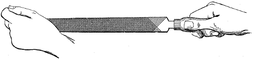
Fig. 2232.
When the file is pushed endways it is termed cross-filing, and the teeth cut on the forward or pushing stroke only, and in this case the file should be held as in Fig. 2232, the end of the file handle abutting against the palm of the right hand. But when the file is held in one hand only, the forefinger may be placed uppermost, and either on the file handle or on the file itself, as may be found most convenient. In cross-filing the file should be relieved of cutting duty on the return or back stroke, but should not be removed from the work surface.
For heavy cross-filing on iron or brass, a 15-inch file is sufficiently large for any of the ordinary duty required by the machinist, and will require all the pressure one man can put on it to enable it to cut freely, and move at a suitable speed.
The workman should for heavy cross-filing stand well off or away from the work so as to require to bend the body well forward. His feet should in this case be spread apart so that when the pressure of the hands is placed upon the file it will relieve the forward foot of a great part of the weight of the workman’s body, which will be thrown upon the file. The rear foot operates during the forward stroke as a fulcrum, wherefrom to push the file.
At each forward stroke the workman’s body should move somewhat in unison with the file; his arms being less extended than would otherwise be the case, and the file being under more pressure and better control.
During the backward stroke the forward foot should again take the workman’s weight, while he recovers the upright position.
For less heavy filing and for smooth filing, the workman should stand more nearly upright and nearer to the work.
The heavier the pressure (either in cross-filing or draw-filing), the coarser the file cuts, and the more liable it is to pin and scratch.
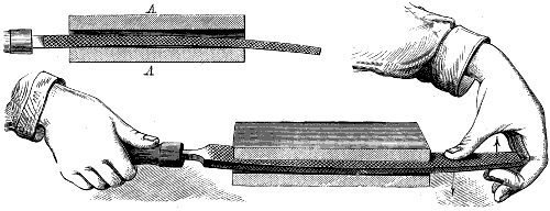
Fig. 2233.
In the case, however, of slim files, the pressure is apt to bend the file, causing it to cut at the edges or ends only of the work, as shown at a, in Fig. 2233. This may be avoided by holding the file as in the figure, the pressure of the fingers in the direction of the arrows causing the file to bend, and produce more straight work.

Fig. 2234.
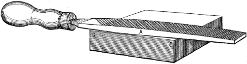
Fig. 2235.
From the nature of the processes employed to cut the teeth of files, they are unequal in height, and as the file in addition to this varies in its straightness or warps in the process of hardening, it becomes necessary in many cases to choose for certain work files whose shape is best suited for it. Suppose, however, that files were produced whose teeth or tops or points were equal in height from end to end of the file, and it would be necessary for the workman to move the file in a true straight line in order to file a straight surface. This the most expert filers cannot accomplish. It is for this reason that hand files are made as in Fig. 2234, being thickest in the middle m, and of a curved taper both towards the point p and the heel h, so that when applied to the work the file will bear on the work at a, Fig. 2235, and be clear of it at b and c, which allows the file motion to deviate from a straight line without cutting away the work too much at b and c. The file curvature also enables any part of the file length to be brought into contact with the work or with any required part of the surface of the same, so as to locate or limit its action to any desired part.
If a bellied file (as this shape of file is sometimes termed) be moved in a straight line it will file flat so long as it is moved to have contact clear across the work, but if the file is concave in its length it can only cut at that part which is in contact with the edge of the work, and the latter must be filed convex.
It becomes obvious then that for flat work a bellied file must be used, and that the belly should preferably be of even sweep from end to end.

Fig. 2236.

Fig. 2237.
But files, whatever their shape, and however evenly formed when soft, warp (as already remarked) in the hardening process, sometimes having crooks or bends in them, such as at e and d, in Fig. 2236. In such a file the teeth at e would perform no duty unless upon work narrower than the length of the concavity at e, while on the other side d, the extra convexity would give the file great value for work, in which particular spots only required to be filed, because the teeth at d could be brought to bear on the required spot without fear of cutting elsewhere.
If, however, we have a taper flat file, such as in Fig. 2234, the thickness being equal from h to m, and a curved taper from m to p only, then it would be impossible to file flat unless only that part from m to p be used, because the heel h would meet the work at the same time as m, and it could not be known where the file would cut, more than that the most prominent teeth would cut the most.
An excellent method of testing the truth of a file, and of finding its high spots is to chalk a piece of board, press the file firmly to it and take several strokes and the chalk will be transferred to the highest parts of the file, showing very distinctly every hill and hollow in the teeth, even on the finest of Groubet files, and it will be found from this test that but very few of the best-made files are true, and that very great care is necessary in selecting a file for flat and true work.
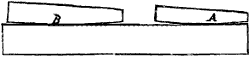
Fig. 2238.
The curvature or belly on a file not only enables but few teeth to be brought into action at any one turn, and thus cause it to cut more freely; but it also enables all parts of the file length to be used and worn equally. Thus in Fig. 2238 are shown two positions of a file, one cutting at a and the other at b, these different locations being due to different levels of the file which may be given by elevating or depressing it at the handle end.

Fig. 2239.
If a file is hollow in one side of its width, and rounding on the other, as in Fig. 2239, the hollow side is unfit for any but the roughest of work, since it will not file any kind of work true; but the rounded side is very effective for flat surfaces, since the number of teeth in action is more limited and their grip is therefore greater, while by canting the file any part of its width may be brought into action. The rounded side is especially advantageous for draw-filing (a process to be hereafter explained).
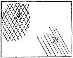
Fig. 2240.
In all cross-filing, whether performed to clean up a surface, remove a maximum of metal, or prepare the work for draw-filing, or for reducing the work to shape, the file should be given a slight lateral as well as a forward motion, and it will be found that this lateral motion is more effective if made from right to left, leaving the file marks in the direction of marks b, in Fig. 2240, because the workman has more control over the file (especially if a large one) than when the lateral motion is from left to right; but this latter motion must be given occasionally to prevent the file from cutting deep scratches, and to keep the file surface true.
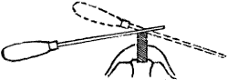
Fig. 2241.
A new file should be used at first on broad surfaces so that the teeth may not grip or bite the work so firmly that the strain will cause their fine sharp edges to break off, which is apt to occur unless their edges are slightly worn off. As a file becomes worn it may be used on narrower work, because the narrower the surface the more readily the file will bite. When a file is much worn, or when it is desired to remove a quantity of metal as quickly as possible, the file may be used at different angles upon the work, as shown in Fig. 2241, which by reducing the number of teeth in action facilitates the cutting, but if this be done with a new file it will break off the points of the teeth.
Cast iron, brass, and copper require a sharper file than do either steel or wrought iron, hence for the first named metals (especially brass and copper) new files are used, and these should not be used upon wrought iron or steel until worn out for the above metals.
In the case of unusually hard cast iron or tempered steel a second-cut file will cut more freely than a coarser grade.
Work to be draw-filed should first be cross-filed with smooth or at the coarsest with second-cut files, so as to remove the scratches of the bastard or rough file before the draw-filing, which should not be done with a rough or bastard file.
Draw-filing consists in moving the file in a line at a right angle to its length, the file being grasped at each end independently of its handle, which may be removed from the file if it be in the way, as in the case of files used on broad surfaces.
Draw-filing is employed for two purposes: first and most important, to fit work more accurately than can be done by cross-filing, and secondly to finish surfaces more smoothly, and lay the grain of the finish lengthwise of the work. The greater accuracy of draw-filing occurs because the high parts of the file can be selected and the file so balanced that this high part covers the place on the work requiring to be filed, while the strokes may be made to suit the length of the spot to be filed.
In draw-filing the file can be moved more steadily than in cross-filing, and will, therefore, rock so much less that even the novice can with care produce very true work.
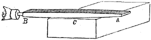
Fig. 2242.
Suppose, for example, that a piece of work requires filing in the middle of its length and half way along its width and half along its length, and a well bellied file may be balanced upon c, Fig. 2242, and grasped at its two ends a and b, and used with strokes of a sufficient length to file half the work length as required.
In draw-filing the file should be pressed to the cut on the pushing stroke only, and not on the return or pulling stroke.
Draw-filing produces with a given cut of file a smoother surface than cross-filing, but it will not remove so much metal in a given time.
In draw-filing short strokes will produce better work than long ones, because with the latter the file cuttings are apt to become locked in the teeth of the file, and cut scratches in the work. This is called pinning, and the pins cutting deeper than the file teeth produce the scratches.
To avoid this pinning the file surface may be well chalked, which will at the same time cause the file to cut smoother although not quite so freely. It is necessary, however, to clean the file after every ten or twelve draw-filing strokes so as to remove the filings. This removes the chalk also, hence it requires occasional renewal. For this purpose lumps of chalk are employed, but great care is necessary in its selection, because it sometimes contains small pieces of flint or other stones, and these score and greatly damage the file teeth.
To dislodge the chalk and filings the file surface may be rubbed two or three strokes with the hand, and the file lightly tapped on the vice back. But it will also be found necessary to occasionally clean the file with a file-brush or file-card. The file-card is brushed across the width of the file so that the wire may reach the bottoms of the rows of teeth and clean them out.
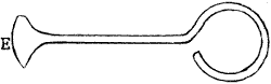
Fig. 2243.
If the pins have lodged too firmly in the teeth to be removed, the scorer shown in Fig. 2243 is employed. This scorer is a piece of copper or brass wire flattened out thin at the end e, which end is pressed firmly to the file teeth and pushed across the width of the file. By this means the thin edge becomes serrated, and the points of the teeth forming the serrations pass down the bottoms of the rows of file teeth and force out the pins. Here it may be remarked that pinning takes place in cross-filing as well as in draw-filing, and is at all times destructive to either good or quick work.
Oil is sometimes used to prevent pinning and produce a dead finish, which will hide scratches, but it is much more dirty than chalk and no more effective. Neither of these substances, however, is employed upon cast iron, brass, copper, or other than the fibrous metals.
In removing the cross-file marks it will be found that the file will cut more freely if it be slightly canted so that it cuts most at and near the edge, as shown in Fig. 2244, the edge a b meeting the work, the file stroke having progressed from c as shown. This is especially advantageous if the metal be somewhat hard or have a hard skin upon it, or in case of a hard spot, because it will enable the file to bite when, if pressed flat upon the work, it would slip over it.
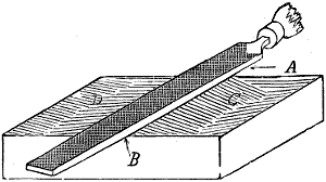
Fig. 2244.
When draw-filing is resorted to, to obtain a very fine surface, to be finished with emery paper and crocus cloth, it is best to reverse the direction of the file strokes so as to cause the file marks to cross and recross as shown in Fig. 2244, where the marks c cross those previously made, which will not only produce smoother work, but it will partly prevent the file from pinning. It will also be found that the draw-filing will be smoother and pinning less liable to occur when the file strokes cross the fibres or grain of the metal than when they are parallel to that grain; hence when the finishing marks are to be left in a line with the grain and a very smooth surface is required, the draw-filing marks should, just before the final finishing, be across the grain, the final finishing being with the grain simply to reverse the direction of the marks.
Half-round files should be well curved in their lengths on the half-round side, so that when applied to the work any part of the file’s length may be brought to bear upon the required spot on the work, as was explained for the flat file, and shown in Fig. 2238. If the flat side is straight or hollow in its length it is of little consequence, because it can be used upon convex or upon narrow surfaces. The sweep or curve of the file should in its cross-section always be less than the curve of the work it is to operate upon, and the teeth should be brought up sharp on the edges, and over the whole area of the half-round side, which is in inferior files not always the case, because the rows of chisel cuts are too far apart in the width of the file; hence, there is along the length of the file between the rows of full teeth, rows that are not brought fully up, which impair the cutting qualifications of the file.
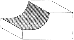
Fig. 2245.
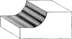
Fig. 2246.
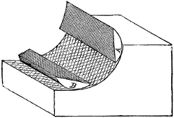
Fig. 2247.
In using a half-round file to cross file it should at each stroke be swept first from right to left, and after a few strokes from left to right, so that the file marks appear first as in Fig. 2245, running somewhat diagonal from right to left, and then, when the side sweep of the file is reversed in direction, the file marks will cross after the manner shown exaggerated in Fig. 2247. Unless this is done, the curve will be apt to have a wave in it as in Fig. 2246, or in large curves there may be several waves, and the same thing may occur if the direction of side sweep is not reversed sufficiently often. The file should also be partly swept around the curve, so that if at the beginning of a stroke it meets the work at the upper position in Fig. 2247, then at the end of the stroke it should be as at the lower one, which will also prevent the formation of waves. The larger the curve the less the amount of this sweep can be, the operator giving as much as convenient for the size of curve being filed.
In draw-filing the file should be slightly rotated, so that if at the beginning of a stroke it stands as at a, Fig. 2247, at the end of that stroke it should stand as at position b, and it should at the same time be given sufficient end motion, so as to cause the file marks to cross as shown.
A round file should always be a little smaller at its greatest diameter than the hole in the work. Before inserting it in the hole it should be rotated in the fingers, and the eye cast along it, to select the part having the most belly, which may then be brought to bear on the required spot in the work, without filing any other place, and without filing away the edges at the ends of the hole. For very accurate work it is sometimes desirable to grind on a round file, a flat place forming a safe edge. So likewise a safe edge flat file requires grinding on its safe edge, because in cutting the teeth a burr is thrown over on the safe edge, rendering it capable of scoring the work when filing close up to a shoulder.
The work should be held as near down to the surface of the jaws of the vice as will allow the required amount of metal to be filed off without danger of the file teeth coming into contact with those jaws, and should be placed so that the filing operation when finished shall be as near as possible parallel with the top of the vice jaws. These jaws then serve somewhat as a guide to the filing operation, showing where the metal requires filing away.
For cutting steel that contains hard spots or places, a second-cut file is more effective than a rough or bastard file.
Rough files are more suitable for soft metals, the bastard cut being usually employed upon wrought iron, cast iron, and steel by the machinist. But in any case the edge of the file is employed to remove small spots that are excessively hard. The file should be clean and dry to cut hard places or spots, and used with short strokes under a heavy pressure, with a slow movement.
When a file has been used until its cutting edges have become too dull for use, it may be to some extent resharpened by immersion in acid solutions; but the degree of resharpening thus obtained has not proved sufficient to bring this process into general or ordinary application; hence, the files are either considered useless, or the teeth are ground off and new ones formed by recutting them.
A recut file is of course thinned by the process, but if properly done is nearly, if not quite, as serviceable as a new one, providing that in grinding out the old teeth the file be ground properly true to curve; but, unfortunately, this is rarely found to be the case.
An excellent method of resharpening files, and also of increasing the bite of new files (which is an especial advantage for brass work), is by the means of the sand blast. The process consists of injecting fine sand against the backs of the teeth by means of a steam jet, and is applicable to all files, from the rasp to the finest of Groubet files. The action of the sand is to cut away the backs of the file teeth, thus forming a straight bevel on the teeth back, and giving a new cutting edge, and the process occupies from three to five minutes.
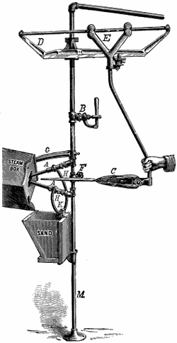
Fig. 2248.
Fig. 2248 represents a machine constructed for this purpose. Steam is conveyed by the piping to the nozzles a, a, which connect by rubber hose h, h to sand pipe k, so that the steam jets passing through a, a carry with them the mixture of quartz, sand, and water in the sand box. By means of the overhead guide frame at d, e the file clamp c is caused to travel when moved by hand in a straight line between the nozzles a, a in the steam box, from which the expended sand and water flow down back to the sand box. Thus both sides of the file are sharpened simultaneously, and from the fixed angles of the nozzles and true horizontal motion of the file the angles of all the teeth are equal and uniform.
To distribute the sharpening effects of the sand equally across the width of the file, the carriage has lateral or side motion, as well as endwise, and on the apparatus represented adjustable rollers regulate this side movement. Having the two motions, any part of the file can be presented to the blast.
The following is from Engineering:—“A comparative trial of the cutting power of the sharpened files was lately made with the following results: A piece of soft wrought iron was filed clean and weighed; 1200 strokes were made by a skilled workman with one side of a new 10-inch bastard file, the iron was again weighed, and the loss noted. The other side of this file was then subjected to the sand blast for five seconds, and 1200 strokes were made with this sand-blasted side on the same piece of iron, great care being taken to give strokes of equal length and pressure in both cases. The iron was then weighed, and the loss found to be double as much as in the first case.
“These operations were repeated many times, counting the strokes and weighing the metal each time, and the quantity cut was found to gradually become less for both sides as these became worn. When the weight of metal cut away by 1200 strokes of the sand-blasted side was found to be no greater than had been cut by the first 1200 strokes of the ordinary side when quite new, a second sand blasting was applied to it for 10 seconds, and in the next 1200 strokes its rate of cutting rose to nearly its first figure. When the cut made by the ordinary side of the file fell to about four-tenths of its cut when new, it was considered by the workman as worn out, and a new file of the same size and maker was used to continue the comparison with the one sand-blasted side; 83 sets of 1200 strokes each and 13 sand-blastings were made on the same side of this file, and in that time it cut as much metal as six ordinary sides. In 99,600 strokes it cut away 14 ozs. avoirdupois of wrought iron, and 16.4 ozs. of steel.
“With an equal number of strokes its average rate of cutting was, on wrought iron, 50 per cent. greater than the average of the ordinary sides, and on steel 20 per cent. greater. As the teeth became more worn, the time of the application of the sand blast was lengthened up to one minute. After the thirteenth re-sharpening its rate of cutting was nine-tenths that of the ordinary side when quite new.
“When the teeth become so much worn that the sand blast ceases to sharpen them effectively, the file can be recut in the usual way, and each set of teeth can be made to do six times as much work as an ordinary file, and to do it with less time and labor, because it is done with edges constantly kept sharp. The time required to sharpen a worn-out 14-inch bastard file is about four minutes, or proportionately less if sharpened before being entirely worn out. Smooth files require much less time. About 4 horse power of 60 lb. steam used during four minutes, and one pint per minute of sand (passed through a No. 120 sieve), and the time of a boy are the elements of cost of the operation.”
Red Marking or Marking.—This is a paint used by machinists to try the fit of one piece to another, or to try the work by a test piece or surface plate. It should be composed of dry Venetian red, mixed with lubricating oil of any kind.
Instead of Venetian red, red lead is sometimes used for marking, but it is too heavy and separates from the oil, and furthermore will not spread either evenly or sufficiently thin, and is therefore much inferior to Venetian red.
It is applied to the surface of the test piece or piece of work, and the latter is brought to bear on the surface to be tested, so that it leaves paint marks disclosing where the surfaces had contact, and therefore what parts of the surface require removing in order to make the surfaces have the desired degree of contact.
When either the test piece or the work can be put in motion while testing, one piece is rubbed upon the other or passed along the same in order that the bearing marks may receive the marking more readily and show the bearing spots more plainly, the operation coming under the head of fitting. When neither piece can be given motion, one is made to mark the other by being struck with a mallet or hammer, or to avoid damage to the work from the hammer blows, a piece of wood or copper is interposed. This operation is termed “bedding.”
The thickness of the coating of marking varies with the kind of work, the finer fit the work requires to be, the thinner the coat of marking. Thus in chipping a thick coat is applied, for rough filing a thinner, for smooth filing a still thinner coat, and so on, until for the finest of work the coat is so thin as to be barely perceptible to the naked eye. When either the work or the testing piece can be given motion and the surfaces rubbed together, a thinner coat of marking may be used. Marking is usually applied with a piece of rag doubled over and over, and bound round with a piece of twine so as to form a kind of paint-brush. This will give the surface a lighter and more evenly spread coat than would be possible with a brush of any kind. For very fine work red marking may be spread the lightest and the most even with the palm of the hand, which will readily detect any grit, dirt, or other foreign substance which the marking may contain from being left exposed.
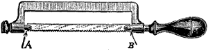
Fig. 2249.
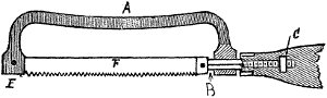
Fig. 2250.
The Hack-Saw.—The hack-saw is employed by the machinist for severing purposes, and also for sawing slots in the heads of screws. The blade should be tightly strained in the frame, which will prevent saw breakage. The ordinary method of doing this is to provide the end of the saw frame with a sliding stud threaded at its end to receive a thumb nut. The studs at each end of the blade should be squared where they pass through the frame, as at a, b in Fig. 2249, so that the blade shall not be permitted to twist. An improved form is shown in Fig. 2250, in which the end e has a saw slot to receive the blade f. At the handle end of the blade it is held by a stud sliding through the frame, being squared at b; at c is a nut let into and screwed in the handle, and into or through the nut is threaded the end of the stud, so that by rotating the handle the blade is strained. The curve in the back at a gives a little elasticity to it, and therefore a better strain to the blade. A hack-saw should always be used with oil, which preserves the cutting edge of the teeth.
In sharpening a hack-saw it is best to rest the smooth edge of the blade on a piece of hard wood or a piece of lead, and spread the tops of the teeth by light hammer blows, which serves a two-fold purpose, first it thickens them and enables them to cut a groove wide enough to let the blade pass freely through, and secondly it enables the teeth to be filed up to a sharp cutting edge with less filing.
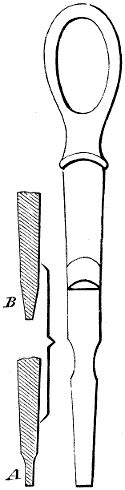
Fig. 2251.
The screw-driver to be used in saw slots should have its end shaped as at a in Fig. 2251, which will tend to prevent it from slipping out of the saw slot, as it will be apt to do if wedge-shaped as at b, because in that case the action of the torsional pressure or twist is to lift the screw-driver out of the slot.
Scrapers and Scraping.—The process of scraping is used by the machinist to true work, and to increase the bearing area of surfaces, while the brass finisher employs it to prepare surfaces for polishing, applying it mainly to hollow corners and sweeps.
For scraping work to fit it together the flat scraper is used, ordinary forms being shown in Figs. 2252 and 2256.
VOL. II. SCRAPERS AND SCRAPING. PLATE IX.
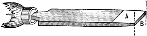
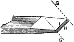
Fig. 2252. Fig. 2253.
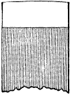
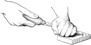
Fig. 2254. Fig. 2255.
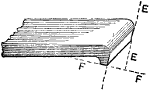
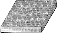
Fig. 2256. Fig. 2257.
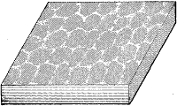
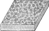
Fig. 2258. Fig. 2259.
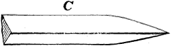
Fig. 2260.
That shown in Fig. 2252 may be made of a flat smooth file, of about an inch wide, and 3⁄16-inch thick, which is large enough for any kind of work. Two opposite faces, one of which is shown at a, are ground beveled so as to leave the end face b about 1⁄16-inch thick. This end face is then ground square as denoted by the dotted lines, producing two cutting edges of equal angles, and therefore equally keen. If it were attempted to grind face b at an angle as denoted by the dotted lines g, in Fig. 2253, the lower edge h would cut too keenly, causing the scraper to chatter and cut roughly, while the upper one i would not cut sufficiently easily.
For very smooth work the scraper may be formed as in Fig. 2256, the front face e being ground slightly out of square as shown, and the bottom face f being given considerable angle to the body of the scraper. For very rapid cutting, however, the front face e may be at an angle of less than 90° to the top of the scraper.
The only objection to this form is that the eye lends no assistance in bringing the edge fair with the work surface. The scraper should not exceed about 6 inches in length, exclusive of the handle, for if longer it will not cut well or smoothly, and its end face should be slightly rounded as in Fig. 2254. Its facets should be ground square or straight and carefully oil-stoned after the grinding, the oil-stoning process being repeated for two or three resharpenings, after which it must be reground upon the grindstone.
The scraper should be grasped very firmly in the hands, and held as in Fig. 2255. It requires to be pressed hard to the work during the cutting and lightly during the backward stroke.
The strokes should not exceed for the roughing courses, say, half an inch in length, the first course leaving the work as represented in Fig. 2257.
The second course should be at a right angle to the first, leaving the work as in Fig. 2258, and after these two courses the work should be tested by surface plate, or with the part to which it is to fit, as the case may be. Previous to the testing, however, the work must be carefully wiped clean with old rag, as new rag or waste is apt to leave ravelings behind. The surface plate should be given a light coat of red marking, and then moved backward, forward, and sideways over the work, or, if the work is small, it may be taken from the vice and rubbed upon the surface plate, and the high spots upon the work will be shown very plainly by the marks left by the plate. The harder the plate bears upon the work the darker the marks will appear, so that the darkest parts should be scraped the heaviest.
After applying the plate, the scraper may again be applied, the marks being at an angle to the previous operation, the testing and marking by the plate and scraping process being continued until the job is complete, appearing as shown in Fig. 2259.
It will be noted that the scraper marks are much smaller and finer at and during the last few scrapings; and it may be here remarked that the scrapings are very light during the last few finishing processes.
The strokes of the scraper being made of a length about equal to the acting width of its edge cuts, makes the scraper mark approximately square, on which account it is sometimes termed “block” scraping. It gives an excellent finish, while not sacrificing the truth of the work to obtain the finish.
The scraper will not remove a quantity of metal so quickly as a file, and on this account it is always preferable to surface the work with a file before using the scraper, even though the work be well and smoothly planed. Not until the file has almost entirely removed the planer marks, and the surface plate shows the surface to be level and true, should the scraper be brought into requisition, the first courses being applied vigorously to break down the surface.
It would appear that scraping might be more quickly done by taking long scraper strokes promiscuously over the work, but in this case the bearing marks are not well defined and do not show plainly, which leads to confusion and causes indecision as to where the most or heaviest scraping requires to be done, whereas in the block scraping the marks are clearly defined and the high patches or spots on the work show very plainly, and the workman is able to proceed intelligently and with precision.
Fig. 2260 represents a three-cornered or “three-square” scraper, which is used principally upon hollow or very small flat surfaces. The half-round scraper is employed upon holes, bores, or large concave surfaces, such as brasses. Both these tools are for vice work, used in the same manner as described for flat scrapers, while all scrapers cut smoother when the edge is kept wetted with water, as is essential when used upon wrought iron, copper, and steel.
Hand Reamers or Rymers.—The hand reamer is employed for two purposes, first, to make holes of standard diameter and smooth their walls, and second, to bring holes in line one with the other.

Fig. 2261.
Fig. 2261 represents an ordinary solid hand reamer for parallel holes. The teeth are ground so that their tops form a true circle, this grinding being done after the reamer has been hardened and tempered, because in these processes the reamer is apt to get both out of round and out of straight.
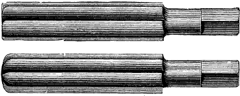
Fig. 2262.
In some practice the reamers are formed as shown in Fig. 2262, and are made in sets of three for each size; the first is slightly taper from end to end, the second is slightly tapered at the entering end for a length about or nearly equal to the diameter, and the third is parallel and rounded on the end like the second, and in many cases only three teeth are employed.

Fig. 2263.
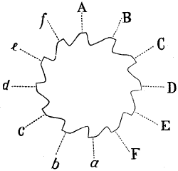
Fig. 2264.
Fig. 2263 represents a reamer in which the distance between the cutting edges a b, Fig. 2264, is greater than between b c, and so on, the spacing decreasing from tooth a to tooth a. The spacing of a, b, &c. to f on the other side is also irregular, so that if the reamer be given half a revolution no two teeth will have arrived at similar positions except a and a, the former arriving at the position occupied by the latter.
Now suppose that a hole to be reamed has a hollow or spongy seam along it, and if the reamer be regularly spaced, there will at this point occur a lateral movement of the reamer that will impair the roundness of the hole, and this lateral movement the irregular spacing tends to prevent.
If a solid reamer is made to standard gauge diameter when new, and the bolts or pins turned to standard diameter, then by reason of the wear of the reamer the work will become gradually a tighter fit and finally will not go together, hence the reamer must be restored to standard diameter, which may be done by upsetting the teeth with a set chisel. Furthermore the workman’s measuring gauges are themselves subject to wear, those for measuring the pins wearing larger and those for the holes wearing smaller, and this again is in a direction to prevent the work from fitting together. It is preferable, therefore, to employ adjustable reamers.

Fig. 2265.
Thus Fig. 2265 represents an adjustable reamer in which the teeth fit tightly into dovetail grooves, that are deeper at the entering than at the shank end of the reamer, so that by forcing the teeth up the grooves towards the shank the diameter is increased.
Both castings and forgings are found to alter somewhat in shape in proportion as their surfaces are removed by the machine tools, so that the shape of the work undergoes continuous alteration.
Suppose, for example, that a piece of metal two inches square and four inches long, has a hole cast in it of an inch in diameter, and when finished it is to be 13⁄4 inches square, 33⁄4 inches long, and have a hole 11⁄8 diameter. Let it be chucked in a lathe or shaping machine and have its surfaces cut down to the required dimensions. Removing the metal to true the first surface will reduce the strain on that side of the casting and alter the shape of the whole body, but this alteration of form will not occur to its full extent until the piece is removed from the pressure of the chuck jaws, or other clamping device holding it in the machine, because this pressure holds it; as a result the surface will not be so true after leaving the machine as it was before. On surfacing the second side of the piece, the internal strain is still further reduced, and a second alteration of form ensues, and so on at the surfacing of every side of the piece. Now let the piece be chucked true to have the hole bored out, and the removal of the metal in the hole will again reduce the internal strain and the form of the body will again alter.
Suppose, however, that the piece after having its surfaces thus removed, and its hole bored as true as may be, were again trued over each surface, and in its bore there will still be at each surfacing and at the boring an alteration of form, although it may be to a very minute degree, and from these causes the use of the reamer for work requiring to be very true becomes indispensable.

Fig. 2266.
Fig. 2266 represents a taper hand reamer with straight flutes. It is preferable, however, to give the flutes a left-hand spiral, as was explained with reference to reamers for lathe work.

Fig. 2267.
The frames of large machines are frequently composed of parts that are bolted together after having the holes for shafts, &c. bored, and to insure the alignment of these holes after the frames are put together a hand reaming bar, such as in Fig. 2267, is employed, a and b being two shell reamers fastened to the bar by a pin.
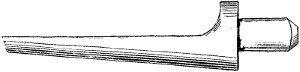
Fig. 2268.
Reamers are sometimes employed to enlarge holes or bring them fair one with another, without reference to their being precise to a designated diameter; thus Fig. 2268 represents a half-round reamer of the form used by boiler makers to bring rivet holes fair, and sometimes by machinists to ream the holes for taper securing pins. The flat face is cut down to below the centre line, so that the back requires no clearance ground upon it.

Fig. 2269.
The square reamer shown in Fig. 2269 is used for rough work generally, although with careful grinding and use it will produce excellent results upon work of small diameter. Brass finishers generally prefer a square reamer to all others for reaming the bores of brass cocks, &c., and some of them prefer that one edge only be sharpened to cut, the other three being oilstoned off so as not to cut, but simply serve as guides. The square reamer is very easily sharpened whether by grinding or oil-stoning; the flat sides are operated on, taking care to keep them straight and the thickness even on the two diameters, so that, the sides being straight and the reamer square, it will cut taper holes whose sides will be straight. If the reamer is not ground square, two only of the edges will be liable to have contact with the work bore, causing the reamer to wabble, and rendering it liable to break.
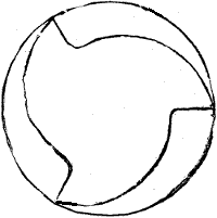
Fig. 2270.
Another and very good form of reamer for the rapid removal of metal is shown in Fig. 2270, having three teeth and a good deal of clearance, which enables it to work steadily and cut freely.