Volume 2 — Chapter XXXIV.—WOOD-WORKING. (continued 2)
Reading edition
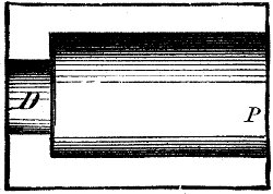
Fig. 2806.
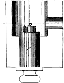
Fig. 2807.
“Fig. 2806 is a plan of half the core box necessary for forming the raised seat. From this construction, it will be seen that the large core, though solid with the branch core, is not solid with that forming the hole in the seat and the part below it; therefore the core prints on the body pattern must be left extra long to give sufficient support in the mould for the overhanging cores. The loose round plug p, is made of the size of the outside of the seat and fitted to the box. The part outside the box is a roughly shaped handle to draw it out by. The diminished part d is a print, and into the impression left by it is inserted the core made in box shown in Fig. 2807. The print d is of the same diameter as the hole in the seat; and the print on the pattern is of the size of the increased diameter below the seat. Large angle valves are made with half a core box by making a branch opening in the box right and left, a semicircular plug being provided. Two half-cores are made with the plug, first in one and then in the other branch opening. The plug p should be in this case only half round.”
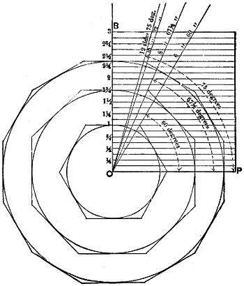
Fig. 2808.
For finding the lengths of the sides of regular polygons, scales, such as shown in Figs. 2808 and 2809, may be used, the construction being as follows:—
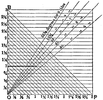
Fig. 2809.
Draw a horizontal line o p, Fig. 2809, and at a right angle to it the line o b. Divide these two into inches and eighths of an inch, and draw lines meeting the corresponding divisions on o p, o b. From the point o draw the following lines: A line at 551⁄2 degrees from line o p, which is to serve for polygons having 9 sides; a line at 521⁄2 degrees to serve for polygons having 8 sides; a line at 49 degrees for polygons having 7 sides; a line at 45 degrees for 6 sides; a line at 40 degrees for polygons having 5 sides. It may be added, however, that additional lines may be drawn at the requisite angle for any other number of sides.
The application of the scale is as follows:—
The point o represents the centre of the polygon; hence from o to the requisite line of division on o b represents the radius of the work. From the line o b to the diagonal line (measured along the necessary horizontal line of division) is shown the length of a side of the polygon. From the point o, measured along the line having the requisite degrees of angle, to the horizontal line denoting the radius of the work, gives the diameter across corners of the polygon. The diameter across the flats of a square being given, its diameter across corners will be represented by the length of a line drawn from the necessary line of division on o b to the corresponding line of division on o p. A cylindrical body is to have six sides, its diameter being 2 inches, what will be the length of each side? Now, the radius of the 2-inch circle of the body is 1 inch; hence, find the figure 1 on line o b and measure along the corresponding horizontal line the distance from the 1 to the line of 45 degrees, as denoted by the thickened line.
A body has six sides, each side measuring an inch in length, what is its diameter across corners? Find a horizontal line that measures an inch from its intersection of the line o b to the line of 45 degrees, and along this latter to the point o is one-half the diameter across corners.
Example 3.—It is desired to find the diameter across corners of a square whose side is to measure 3 inches. Measure the distance from the 3 on line o p to the 3 on line o b, which will give the required diameter across corners.
This scale lacks, however, one element, in that the diameter across the flats of a regular polygon being given, it will not give the diameter across the corners. This, however, we may obtain by a somewhat similar construction. Thus, in Fig. 2808, draw the line o b, and divide it into inches and parts of an inch. From these points of division draw horizontal lines; from the point o draw the following lines and at the following angles from the horizontal line o p:—
A line at 75 ° for polygons having 12 sides.
„ 72 ° „ 10 „
„ 67 1⁄2° „ 8 „
„ 60 ° „ 6 „
From the point o to the numerals denoting the radius of the polygon is the radius across the flats, while from point o to the horizontal line drawn from those numerals is the radius across corners of the polygon.
A hexagon measures 2 inches across the flats, what is its diameter measured across the corners? Now, from point o to the horizontal line marked 1 inch, measured along the line of 60 degrees, is 15⁄32 inches; hence the hexagon measures twice that, or 25⁄16 inches across corners. The proof of the construction is shown in the figure, the hexagon and other polygons being marked for clearness of illustration.
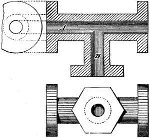
Fig. 2810.
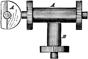
Fig. 2811.
Let it be required to make a pattern for a section of pipe such as shown in section and in plan in Fig. 2810, which is from “The Pattern Maker’s Assistant.” This pattern would be made to mould, as shown in the section, lying horizontally, and must therefore be made in two halves, the line of joint for the two halves being along a b in Fig. 2811.
“The body a and the branch b would be made separate from the flanges, and would be reduced in diameter at the ends to receive them. To form a, take two pieces of timber, say three inches longer than the length of a, including the core prints, and measuring a little more than half the diameter of the pipe one way, and a little larger than the full diameter of the pipe the other way, and glue them together at the ends for a distance of 11⁄2 inches, which will serve to hold them while turning them in the lathe.
“The pieces may then be turned in the lathe to the required diameter. During this turning, however, it is essential to insure that the joint of the two pieces be exactly in the centre, otherwise one half of the pattern will be (when the halves are separated) thicker than the other.
“The ends are then turned down to receive the flanges, the reduced diameter being necessary so as to leave a shoulder for the flanges to abut against to keep them true, or at a right angle to the axial line of the body. The branch is turned up in the same way, and the flanges are then turned and put on.
“The end of the branch may be cut to fit the circumference of the body as follows:—
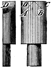
Fig. 2812.
“Set a bevel square to an angle of 45°. Take the halves of the branch apart, and rest the stock or back of the bevel against the end face, and let the blade lie on the joint face, and mark two lines a b in Fig. 2812, which lines must just meet in the centre of the branch at the end. Cut away the angular pieces c and d down to the lines a b. This performed on each half will leave them when given a quarter turn as shown in Fig. 2812, and the curve shown by the junction of the horizontal with the vertical shading lines is the curve for the end; hence the surface covered with the horizontal lines requires to be cut away.
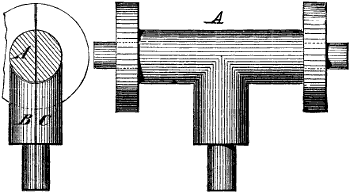
Fig. 2813.
“When this is done on both halves the branch will fit to the body, as shown in Fig. 2813, in which a is the body and b c the two half branches. For a temporary pattern the branch may be fastened to the body with a few screws; but for a permanent pattern it should be glued also, which is done as follows:—
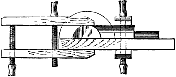
Fig. 2814.
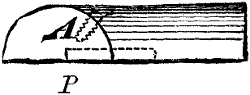
Fig. 2815.
“Lay one half of the body a, Fig. 2813, on a board, with the flange overhanging to be out of the way, and clamp it there; lay the branch also on the board, and draw it firmly up to the body by clamps, while also clamping it flat down to the board, as shown in Fig. 2814. This will insure that the joint faces are true with one another, that is, lie in the same plane. Paper should, however, be placed between the joint faces and the board to prevent them from becoming glued to the board, and the edges, therefore, from breaking away. The second half can be put together as the first one, paper being put between the two to prevent them from being glued together; and to further strengthen the joint, let into each half a piece of hard wood p, Fig. 2815, and put in the screw shown at a.
“Suppose now that the diameter of the branch had been smaller than that of the body of the pattern, then the length of curve necessary on the branch end to let it abut fairly against the cylindrical pattern body may be found as follows:—
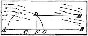
Fig. 2816.
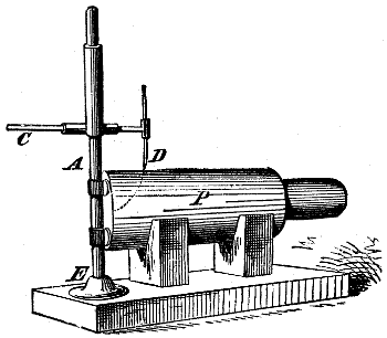
Fig. 2817.
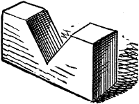
Fig. 2818.
“Draw on a piece of board the line a b, Fig. 2816, and from any point c mark a semicircle equal in radius to that of the radius of the body of the pattern, draw the line e parallel to a b, and distant from it to an amount equal to the radius of the branch, then from the junction of e with the semicircle as at d, mark the line f at a right angle to a b. Let it now be noted that the semicircle a g represents half the pattern body, and e d f b the branch; hence from f to g is the length of the branch end that will require to be curved to fit the circumference of the body, while it is also the length to be added to the distance the branch requires to stand out from the body. To draw the curve on the end d f g of the branch the gauge or marking instrument, shown in Fig. 2817, is employed. The branch p is placed in V-blocks (Fig. 2818), resting upon a plane surface. The gauge consists of a stand e carrying a vertical bar a; upon a is the closely fitting cross-tube carrying the arm c, which in turn carries the marking pointer d, which is set distant from the centre of the bar a to the amount of the radius of the piece of work or the cylinder is to fit against.
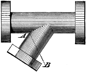
Fig. 2819.
“If the branch required to stand at an angle to the body, as in Fig. 2819, the marking may be performed by the same gauge and in the same manner, but the axial line of the branch must be set, when marking one side, at an acute angle to the axial line of a, and at an obtuse angle to a when turned over to mark the other side, which may be done in each case by raising one of the V-blocks until the branch lies in either case at the same angle to a as it will require to stand to the body on which it is to fit.
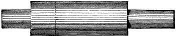
Fig. 2820.
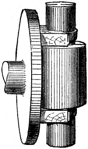
Fig. 2821.
“When the body is much larger in diameter than the branch, a hole may be bored in the former to receive the end of the latter, by giving to the branch end a stem, as in Fig. 2820, and then cutting in the body a recess for the branch end and its additional stem. This recess may be cut out in the lathe, chucking the body as in Fig. 2821.
“Should it occur that one end of the T is of larger diameter than the other, one chucking V must be deeper than the other, and we may find their respective depths by the following process:—
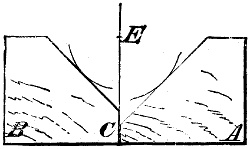
Fig. 2822.
“Draw line a b, Fig. 2822, which line represents the chuck face. Let point c represent the centre of the lathe. Mark line c e and set a pair of compasses to the radius of the body of the pattern at the centre of the branch location. Then take a radius from c and about 1⁄16 inch up from line a b, and with this radius we mark on the line c e the point e. From this centre we mark the two arcs having radii corresponding to the unequal diameters of the pattern at the location where the chucking V’s are to be placed. We then draw tangent lines to each of these arcs, and thus obtain the correct depth of V necessary to hold the axial line of the pattern parallel to the lathe chuck.
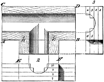
Fig. 2823.
“The core box would, unless the pattern were a small one, be built up in courses, as shown in Fig. 2823. The box would be drawn in plan, and end and side views drawn as shown, so as to draw in the half circle representing the bore of the half-core box and mark off the courses as from 1 to 6. These courses need not be of equal or of any particular thickness, but may suit that of any suitable timber at hand. Courses 1 and 2 should extend over the whole outline of the box, while the pieces 3 and 4 are made in width to suit the curvature of the core as shown, and to extend the full length of the box. The pieces 7, 8, 9, and 10 are of the length of the branch, and are made in width to suit the curvature of the branch core. If the branch core were a short one it could be cut out of the solid; but in any event, the grain of the wood should be as shown, and the holding pieces at g and h should be employed.”