Volume 1 — Chapter IX.—DRIVING WORK IN THE LATHE.
Reading edition
The devices employed to drive work that is suspended between the lathe centres are shown in the following illustrations.
They are termed lathe dogs, drivers, or carriers. It is to be observed, however, that since the term dog is also applied to a device for holding work to the lathe face plate, as well as to the jaws of chucks, either the term driver or the English term carrier is preferable to the term dog.
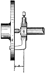
Fig. 745.
Fig. 745 represents a lathe dog, driver, or carrier d, in position to drive a piece of work in the lathe. It is obvious that the work is secured within the carrier or driver by means of the set-screw shown. The tail of the driver here shown is bent around to pass within the slot provided in the face plate, a plan which is convenient, but is objectionable, because in this manner of driving the work two improper strains are induced, both of which act to spring or bend the work. The first of these strains is caused by the carrier being driven at a leverage to the work, as shown at a in the figure, which causes the live centre to act as a fulcrum, from which the work may be bent by the strain caused by the cut.
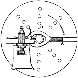
Fig. 746.
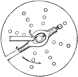
Fig. 747.
The second strain is caused by driving the carrier from one side or end only, and is shown in Fig. 746, where the dog receives the face-plate pressure at the point a, and the cut or resistance being on the opposite side of the work, the leverage of the driving point causes a tendency to lift the work in the direction of the arrow c. The direction of this latter strain, however, varies as the work revolves. For example, in Fig. 747 the dog is shown in position at another point in its revolution, and the point a, where the power is applied to the carrier, is here on the same side as the tool cut; hence there is less tendency to spring the work. It becomes obvious then, that work driven in this manner will be liable to be oval, or out of round, as it is commonly termed.
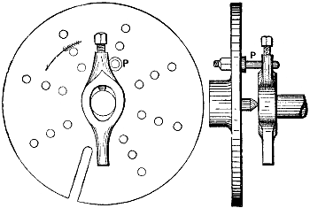
Fig. 748.
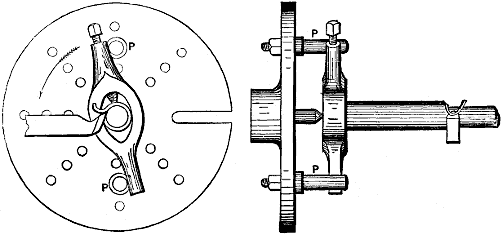
Fig. 749.
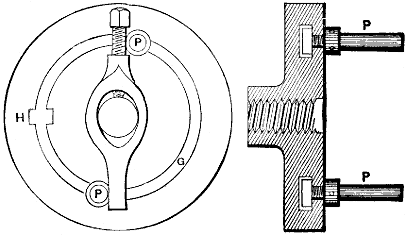
Fig. 750.
The methods of overcoming these two sources of error are as follows: Instead of the end of the dog being bent around to pass within the slot in the face plate, as in Fig. 745, the leverage a in that figure may be avoided by the means shown in Fig. 748, in which a driver having straight ends is used, and a pin p is fastened to the face plate to drive the carrier. But this does not remove the tendency (shown in Fig. 746) acting to spring the work from the pressure of the cut; hence, to obviate this latter tendency, two driving-pins p p, in Fig. 749, are sometimes used with the idea of driving the work from both sides, and thus equalizing the strain. But this is effective only when each pin is in working contact with the dog. This condition is difficult to secure for several reasons. First, suppose the two ends of the carrier to be of equal thickness, and the driving-pins to be of equal diameter, while the work receiving hole of the carrier is quite central to these two ends, then the work also must be true, in order to cause the pins to act equally on the ends of the carrier. Hence, this method is only applicable, even if all the above conditions be fulfilled, to the finishing cuts, and these would have to be taken on work that had been sprung in the roughing cuts, so that it would be difficult to obtain accurate results. A nearer approach to correctness is therefore sought by various means. Thus, Fig. 750 represents a face plate provided with an annular T-groove, having a cut at h to admit two nuts into which the pins p are screwed. These pins may be tightened lightly, so that they will slip under the pressure of the roughing cut, and thus come to an equal bearing upon the carrier or work, as in case of the arms of a pulley where a carrier is not used. When the pins have adjusted themselves to have as near as may be an equal driving bearing, they may be tightened up. By this means the pins are compelled to act at an equal leverage upon the carrier or work, but there is no assurance of an equal degree of pressure of the pins p.
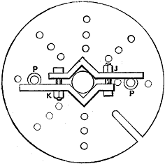
Fig. 751.
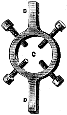
Fig. 752.
Another method is shown in Fig. 751, in which a clamp in two parts is employed, the driving-pins p fitting into two holes equidistant from the lathe centre, while loosening one bolt, j or k, and tightening the other is resorted to, to equalize the driving contact on the two arms, but in this case again there is no certainty that the two pins will drive equally, and there is danger of drawing the work somewhat out of true. Another form is shown in Fig. 752, the idea being to equalize the pressure of the driving pins, by means of the four screws, but here again, there is no means of knowing whether the driving pressure is equalized.
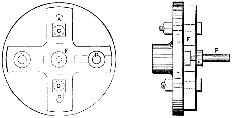
Fig. 753.
The best form of driver is shown in Fig. 753, which represents a Clement’s driver. The driving-plate f has four slots; two of them, a and b, pass entirely through this plate to admit bolts c d, which have a shoulder, so that they may be secured firmly to the lathe face plate, but which are an easy fit in the plate f, so as to permit it to move upon the lathe face plate. The other two are T-shaped slots to receive nuts, into which the pins p p are to be screwed. The bolts c d drive f, and the pins p drive the work, the freedom of the plate e to move upon the lathe face plate permitting this strain-equalizing action of the driving-plate and driving-pins.
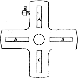
Fig. 754.
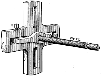
Fig. 755.
Sometimes, as in cutting screws, the work requires to be revolved backwards, without having any lost motion between the arm and carrier, or in other words, the carrier must revolve backwards as soon as the face plate does. To accomplish this, a common plan is to tie the driver or carrier to the driving-pin, but a better plan is to employ a bent tailed dog and secure its end in the face-plate slot. A convenient form of face plate for this purpose is shown in Fig. 754, a, b, c, and d, being slots, and e a set-screw for binding the dog as shown in Fig. 755.
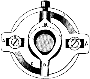
Fig. 756.
For special lathes in which the work is of uniform diameter, the driving pins p, Fig. 753, may be replaced by solid jaws, thus in Fig. 756 is a Clement driver, such as is used on axle lathes, c c being driving lugs in place of the pins p in figure.
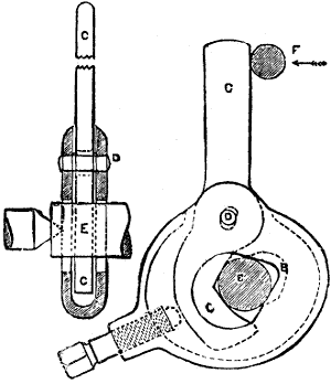
Fig. 757.
To prevent the ends of the set-screw or screws of the driver from damaging the surface of finished work, the form of driver shown in Fig. 757 has been patented in England. It consists of a disc arched to receive a lever c, which is pivoted in the disc at d. A set-screw provided in the disc binds one end of the lever to the work, and as the pressure to drive the work is applied at the other end of the same lever, it serves to assist (to some extent) the set-screw in binding the lever to the work. The work is held between a V in the disc and one on the lever, the object being to provide a large area of contact, and thus prevent the damage to finished work which screw ends are apt to cause.
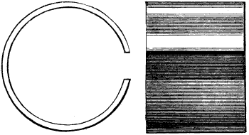
Fig. 758.
The same end may be obtained for ordinary drivers by using a copper or brass ring, such as shown in Fig. 758, which may be opened or closed, within certain limits, to suit the diameter of the work, being placed on the end of the work, and within the dog, to receive the pressure of the set-screws.
One such ring will serve for several diameters of work, springing open when forced, under hand pressure, upon the work, or closing upon the work as the pressure of the dog set-screw is received. It is obvious that the split of the ring should be placed diametrally opposite to the dog set-screw.
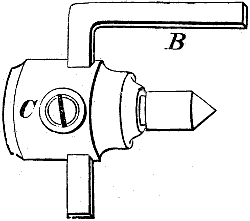
Fig. 759.
In very small lathes the driver is sometimes driven by the device shown in Fig. 759, which consists of a small chuck, screwed on the live spindle, and containing the live centre and a driving arm b, which passes through the chuck, and is set to any required distance out, by the set-screw c. The objection to this is, first, that either the live centre must be very short, or the arm b must be very long; and, second, if the chuck wears out of true, it carries the live centre also out of true; hence this class of driver is but little used, even in foot lathes.
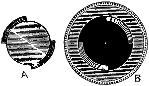
Fig. 760.
In small drivers of this kind it is sometimes the practice to cut away rather more than one quarter of the thread on each side of the live spindle as shown in Fig. 760 at a, and to then cut away one quarter of the thread on each side of the bore of the driver as at b in the figure. This enables the driver to be passed upon the spindle and screwed home with one quarter of a turn, thus saving time in putting on and taking off the driver.
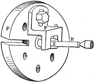
Fig. 761.
Fig. 761 illustrates a work driver very convenient for turning bolts. It consists of a piece of iron or plate p bolted to the lathe face plate f, and having jaws so as to fit to the sides of the bolt b and drive it. This not only saves the time that would otherwise be required to put on a driver or carrier but leaves the underneath face of the bolt clear to be faced up by the turning tool, an example of its use being shown in connection with the knife tool or facing tool.
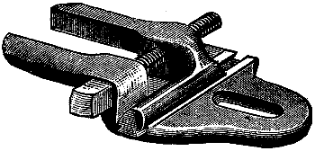
Fig. 762.
Fig. 762 represents a driver of this kind having a sliding jaw so that it may be set for different sizes of bolt heads. When the driving end of the work is threaded an ordinary dog or driver cannot be used because its screw would damage the thread on the work. A common method of overcoming this difficulty is to place over the ring a split ring of copper, or to place on it two nuts, putting a common dog on the end nut. It is better, however, to use a driver, threaded part of the way through, as in figure 762 (from The American Machinist) and to screw it upon the work.
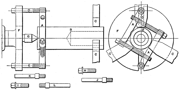
Fig. 763.
Fig. 763 represents a very useful form of work driver designed by Mr. William A. Lorenz. It consists of two jaws a, a held together by two screws, and threaded to receive two driving screws d, e in the figure, which enable it to be used to hold work to the live centre as is necessary when using the steady rest, as is shown in the figure, in which b represents the work and c the jaws of the steady rest. It is obvious that the dog may be thus employed to chuck work independently of the steady rest, because the live centre may be removed, and the face of the work held against the face of the chuck, the short screws h being used instead of the long ones d, e.
If the carrier is used to simply drive the work without clamping it to the live centre or face plate, one or both of the screw pins j, k may be used in place of bolts d, e, the carrier being balanced when both are used.
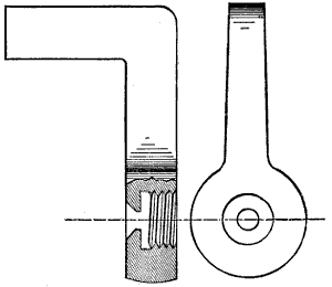
Fig. 764.
Fig. 764 represents a driver, carrier, or dog threaded in its bore to drive threaded work, which the screw of the ordinary dog would obviously damage.
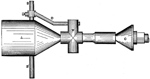
Fig. 765.
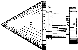
Fig. 766.
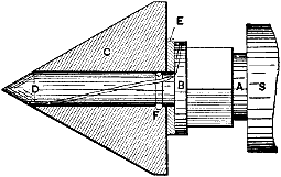
Fig. 767.
Fig. 765 represents an excellent driver for cored work such as the piece w. Its hub a is screwed on the live spindle in place of the face plate, and carries the rods b, b′, both of which are adjustable in the distance they stand out from a, so that b may be set to suit the work, and b′ set out sufficiently to balance b and d. The driving arm d is adjustable along b, and by being bent to the form shown is more out of the way, and obviates the necessity of using a dog on many kinds of work. The other end of the work is shown supported by a cone centre c, whose construction is shown in Figs. 766 and 767. Its object is to avoid the wear that occurs at the mouth of the hole in cored work, when it is run on the dead centre, and to avoid the necessity of plugging the hole to provide a temporary centre. In the figures, a represents a stem (fitting into the tailstock spindle s, in place of the ordinary dead centre), having a collar b and carrying the cone c. The work is supported upon c, which revolves upon the stem of a. At e is a raw-hide washer, intended to prevent the abrasion which would occur on the faces of b and c. The pin f prevents c from coming off d, one half of its cross section being in c, and the other half in a semicircular groove running around d. An oil groove is provided through the collar b, and passes along the stem d. This is an exceedingly handy device for cored work, and may also be used to sustain work against the lathe face plate, while chucking the work true by its bore.
The work drivers employed by wood turners, for work held between the lathe centres, are as follows:—
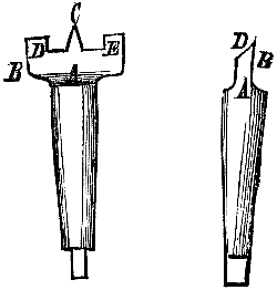
Fig. 768.
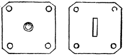
Fig. 769.
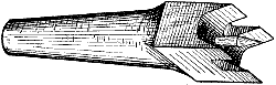
Fig. 770.
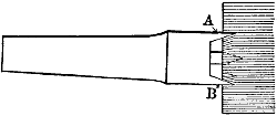
Fig. 771.
Fig. 768 represents two views of a fork centre to be placed in the cone spindle of the lathe, and serve as a live centre, while also driving the work; c is a sharp conical point, which should run true, because it serves to centre the work; d, e are two wings which enter the wood to drive it. This device answers well for work that can be finished without taking it in and out of the lathe, it being difficult to place the work in the lathe so as to run true after removal therefrom; in case, however, that this should become necessary, the work should be replaced so that each wing falls into its original impression. For heavy work this device is unsuitable, hence the two plates shown in Fig. 769 are employed, being termed centre plates. They are composed of iron and are held to the work by screws passing through the respective holes shown at the corners of the plates. The plate having the round centre hole is for the dead centre end of the work, while that having the rectangular slot is for the live centre end of the work. The rectangular slot is made a close fit to the wings of the fork centre shown in figure. Figs. 770 and 771 represent a spur centre designed to hold pieces of soft wood, that may be liable to split from the pressure of the centres. The spurs are made parallel on their outer surfaces, while the inner ones are at an angle, so as to close the wood around the central point, and not spread the wood outwards. The plate for the dead centre is formed on the same principle as is shown in figure 769.
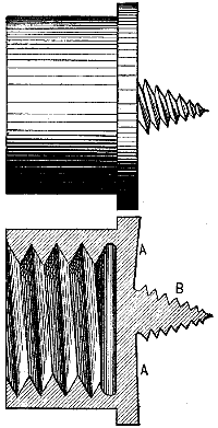
Fig. 772.
Another form of chuck centre or driving centre for wood work is shown in Fig. 772, being especially useful when the work cannot be supported by the lathe dead centre. The body a screws on to the thread on the live spindle of the lathe, while the work screws on the pointed screw b, which will hold disc-shaped pieces of moderate diameter, as about 4 or 5 inches, leaving its face to be operated on as may be desired. To prevent b from splitting the work, or when hard wood is to be turned, a small hole may be bored up the work to permit b to enter sufficiently easily.
When a piece of work to be turned between the lathe centres is of such a form that there is no place to receive centres, provision must be made to supply the deficiency.
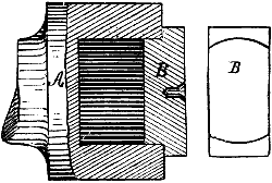
Fig. 773.
In Fig. 773, for example, a temporary centre b is fitted into the socket to receive the centre.
In small work that has been drilled or bored, a short mandrel is used instead of the piece b.
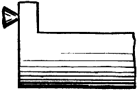
Fig. 774.
If a half-round piece is to be turned it should be forged with a small projecting piece to receive the lathe centre, as in Fig. 774.
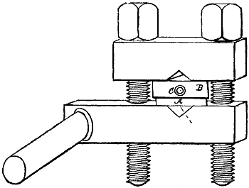
Fig. 775.
When the end of the work is flat and not in line with the axial line of the main body of the work, a piece of metal to contain the centre may be held to the work by a driving clamp, as in Fig. 775, in which a represents the end of the work and b a temporary piece containing the centre c. In this case it is best to make the centre c after the piece b is clamped to the work.
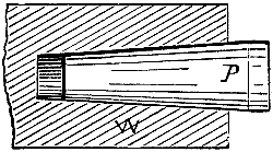
Fig. 776.
To provide a temporary centre for a piece having a taper hole, a taper plug is used, as shown in Fig. 776, w representing the work and p the plug, which must be an accurate fit to the taper of the hole, and must not reach to the bottom of the hole.
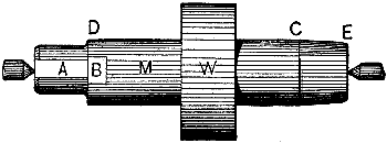
Fig. 777.
Mandrels or Arbors.—Work (of about 6 inches and less in diameter) that is bored is driven by the aid of the mandrel or arbor, which is held between the lathe centres, as in Fig. 777, in which w represents a washer and m the mandrel, driven into the washer bore so as to drive it by friction. At a is a flat place to receive the set-screw of the driver or lathe dog, and at b a flat place upon which the diameter of the mandrel is marked. The mandrel diameter is made slightly larger at d than at c, so as to accommodate any slight variation in the diameter of holes bored by standard reamers, which gradually reduce in diameter by wear; thus if a reamer be made 11⁄1000 inch diameter, with a limit of wear of 1⁄1000 inch, then the mandrel may be made 1 inch at c and 11⁄1000 inch at d. It is well to taper the end of the mandrel from c to e about 1⁄2000 inch, so that it may enter the work easily before being driven in. Instead, however, of driving mandrels into work, it is better to force them in under a press. If driving be resorted to a lead hammer, or for very light mandrels a raw-hide mallet, may be used.
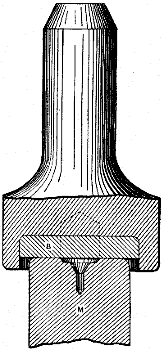
Fig. 778.
In the absence of a lead hammer, a driver, such as in Fig. 778, is a good substitute, consisting of a socket containing babbitt or some other soft metal at b (the mandrel being represented by m). If copper be used instead of babbitt a hole may be drilled through it, as denoted by the dotted lines.
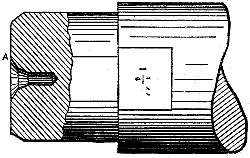
Fig. 779.
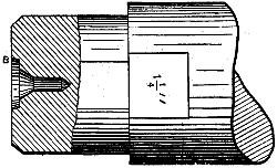
Fig. 780.
The centres of mandrels should either have an extra countersink, as at a in Fig. 779, or else the cut should be recessed as at b, Fig. 780. Mandrels are best made of steel hardened and ground up after hardening.
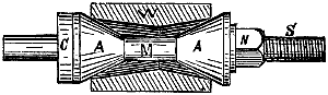
Fig. 781.
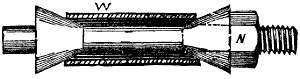
Fig. 782.
If the bore of the work is coned, and of too great a cone to permit the mandrel to be driven, and drive the work by friction, the cone mandrel shown in Fig. 781 may be used. m is the mandrel in one piece with the collar c. The work w is held between two cones a, a, which slide a close fit upon the mandrel, and grip the work by screwing up the nut n, there being a thread upon the mandrel, as at s, to receive the nut. It is obvious, however, that work having a parallel bore may also be held by the cone mandrel, as shown in Fig. 782.
To obviate the necessity of having the large number of mandrels that would be necessary so as to have on hand a mandrel of any size that might happen to be required, mandrels with provision for expanding or contracting the diameter of the parts used to hold the work are made.
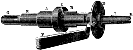
Fig. 783.
Thus in Fig. 783 is shown Le Count’s expanding mandrel, in which g h is the body of the mandrel, turned parallel along a certain distance, to fit the bore of the sleeve a, which is a close-sliding fit on this parallel part of e.
From the end h of the mandrel there extends towards the end g four dovetail grooves, which receive four keys b. The heads of these four keys are enclosed and fit into an annular groove provided in the head c of the sleeve a, so that moving the sleeve a along the mandrel causes the four keys to slide simultaneously in their respective grooves.
Now these grooves, while concentric at any one point in their transverse section to the axis of the mandrel, are taper to that axis, so that sliding the sleeve a along the parallel part of the mandrel increases or decreases (according to the direction in which a is moved) the diameter of the keys.
If the sleeve be moved towards the end g, the keys while sliding in their taper grooves recede from the axis of the mandrel, while if moved towards h they approach the axis of the mandrel, or what is the same thing, if the sleeve be held stationary and the body of the mandrel be moved, the keys open or close in diameter in the same manner; hence all that is necessary is to insert the mandrel in the bore of the work, and drive the end g, when the keys will expand radially and grip the work bore.
The keys, it will be observed, are stepped on their diametral or work-gripping surfaces, which is done to increase the capacity of the tool, since each step will expand to the amount equal to the whole movement of the keys in their grooves or slots.
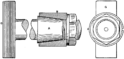
Fig. 784.
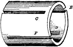
Fig. 785.
Mandrels or arbors are sometimes made adjustable for diameter by forcing a split cone upon a coned plug, examples being given in the following figures, which are extracted from Mechanics. In Fig. 784, a is a cone having the driving head extending on both sides of the centre so as to balance it. Over its coned body fits the shell b, which is split, as shown in Fig. 785, the splits c, d being at a right angle to splits e, f.
It is obvious that the range of adjustment for such a shell is small, but several diameters of shell may be fitted to one cone, the thickness being increased to augment the diameter. The diameter of the shell should be made to enter the work without driving, the tightening being effected by screwing the nut up to force the shell up the cone.
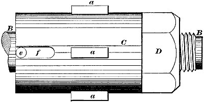
Fig. 786.
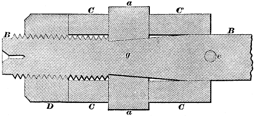
Fig. 787.
Figs. 786, 787, 788, and 789 represent an expanding mandrel designed by Mr. Hugh Thomas, of New York City. The body b of the mandrel is provided with a taper section g, and either three or four gripping pieces a, a, a, a, let through mortises or slots in a sleeve c, which fits the body of the mandrel at each end.
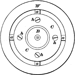
Fig. 788.
This sleeve when forced up the mandrel by the nut d, carries the gripping pieces along the cone at g, and causes them to expand outwards and grip the bore of the work, which is shown in the end view in Fig. 788 to be a ring or washer w.
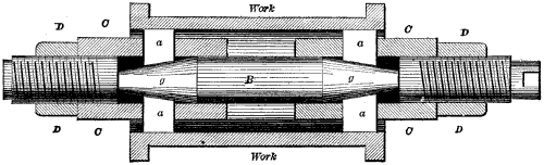
Fig. 789.
The advantage of this form is that the cone at g can be easily turned or ground to keep it true, and the gripping pieces a may be fastened in their mortises by means of the screws shown at h in the end view, and thus kept true. It is obvious that for long work there may be gripping pieces at each end of the mandrel, as in Fig. 789, and the work will be held true whether its bore be parallel, stepped, or taper, a valuable feature not usually found in expanding mandrels.
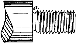
Fig. 790.
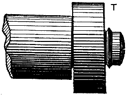
Fig. 791.
When a mandrel is used upon work having its bore threaded the mandrel also must be threaded, and must abut against a radial face, as at a, in Fig. 790, because otherwise the pressure of the cut would hold the work still while the mandrel revolved, thus causing the work to traverse along the mandrel. If the thread of the mandrel be made so tight a fit that it will drive the work by friction it will require considerable force to remove the work from the mandrel, so much so, in fact, that finished pieces would be much damaged in the operation. It is better therefore to have the work such a fit that it can be just screwed home against the radial face of the mandrel under heavy hand pressure (if the work be not too heavy for this, in which case a clamp may be employed). Small work, as nuts, &c., are turned on a mandrel of this kind, which has a stem, and fits into the cone or live spindle in the same manner as the live centre, which will drive work up to about 1 inch in diameter without fear of slipping. Threaded mandrels that are in frequent use soon become a loose fit to the work by reason of the thread wear, with the result that if the face of the work is not true with the thread, it meets the mandrel shoulder, as in Fig. 791, and as the nut cants over, one side as t in the figure, is turned too thick. When the nut is reversed on the mandrel, the turned face will screw up fair against the mandrel shoulder, and the faces of the nut, though true one with the other, are not square with the axis of the thread, and will not therefore bed fair when placed in position upon the work.
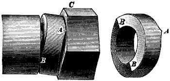
Fig. 792.
To obviate this difficulty we have Boardman’s device, which is shown in Fig. 792. It consists of a threaded mandrel provided with a ring, with two rounded projections a, a and b, b, on each radial face, those on one side being at a right angle to those on the other. This ring adapts itself to the irregular surface of the nut and by equally distributing the pressure on each side of the nut destroys the tendency to cant over, hence the nut may be turned true, notwithstanding any irregularity of its radial faces, and independently of its fitting the arbor or mandrel thread tightly.
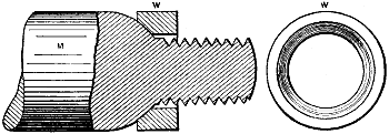
Fig. 793.
Another form of mandrel for the same purpose is shown in Fig. 793, the mandrel being turned spherical, instead of having a square shoulder, and the washer w being cupped to fit, so that the washer will cant over and conform to the nut surface.
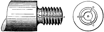
Fig. 794.
The mandrel thread may be caused to fill the nut thread better if it be provided with three or more splits a, b, c, Fig. 794, a hole d being drilled up the centre of the mandrel, the thread may then be turned somewhat large, the splits permitting the thread to close from the nut thread pressure.

Fig. 795.
When a mandrel is fitted to the sockets for the lathe centre, it should have a thread and nut, as shown in Fig. 795, so as to enable its extraction from the socket without striking it, as has been described with reference to lathe centres.
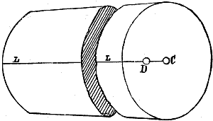
Fig. 796.
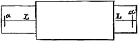
Fig. 797.
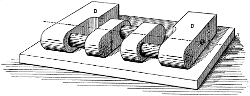
Fig. 798.
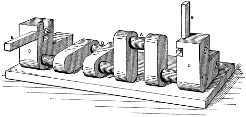
Fig. 799.
Mandrels may be employed to turn work, requiring its outside diameter to be eccentric to the bore, by the following means:—In Fig. 796, let the centre c represent the centre of the mandrel, and d a centre provided in each end of the mandrel, distant from c to one half the amount the work is required to be eccentric. The mandrel must be placed with the centres d receiving the lathe centres. In this operation great care must be taken that a radial line drawn on each end of the mandrel, and passing through the centre of the centres d, shall exactly meet and coincide with the line l drawn parallel to the axis of the mandrel. If this be not the case the work will be less eccentric at one end than at the other. As it is a somewhat difficult matter to test this and ascertain if the mandrel has become out of true from use, it is an excellent plan to turn such a mandrel down at each end, as shown in Fig. 797, and draw on it the lines l, l, which correspond to the line l l in Fig. 796. If then a steel point be put in the lathe rest and fed in to the work, so that revolving the latter just causes the tool point to touch the lines l at each end, or if the tool point makes long lines as at a, a, the two lines l, l, should intersect the lines a, a at the centre of their respective lengths. The lines l l should be marked as fine as possible, but deep enough to remain permanently, so that the truth of the eccentricity of the mandrel may be tested at any time. An equivalent device is employed in turning the journals of crank shafts, as is shown in Figs. 798 and 799, in which d, d are two pieces fitted on the ends of the crank shaft, being equal in thickness to the crank throw, as shown at a, b in the figure, so that when d, d lie in the same plane as the crank cheeks (as when all will lie level on a plate, as in the figure) the centres c will be in line with the journal in the crank throw. Pieces d are broadened at one end to counterbalance the weight of the crank, which will produce more true work than counterbalancing by means of weights bolted to the face plate of the lathe, as is sometimes done, causing the crank throw to be turned oval instead of round. In the case of a double crank, however, the centre pieces cannot be widened to counterbalance, because what would counterbalance when the centres a in Fig. 799 were used, would throw the crank more out of balance when centres b were used for the throw b. In this case, therefore, the centre pieces are provided with seats for the bars e, e, which may be bolted on to carry the counterbalancing weights, the bars being changed on the centre pieces when the centres are changed. The bars, for example, are shown in their position when the centres a are being used to turn up the journal a, the necessary amount of weight for counterbalancing being bolted on them with a set-screw through the weight.
The centres are steel plugs screwed tightly into the pieces d, and are hardened after being properly centre-drilled and countersunk.
To enable the pieces d to be easily put on and taken off, it is a good plan to make the bore a tight fit to the shaft and then cut it away as at e, as shown in Fig. 801, using set-screws to hold it.
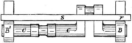
Fig. 800.
Great care is necessary in putting in the work centres, since they must, if the crank throws are to be at a right angle one to the other, as for steam engines, be true to the dotted lines in figure, these dotted lines passing through the centre of the axle and being at a right angle one to the other. If the thickness of the centre pieces are greater than the crank throws they may be adjusted as in Fig. 800, in which b, b′ represent the centre pieces, and c the crank, while s is a straight-edge; the edge surfaces of b, b being made true planes parallel to each other on each arm, and parallel to the axial line of the bore fitting the end of the crank axle.
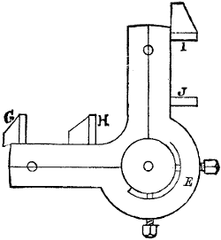
Fig. 801.
The straight-edge is pressed at one end, as at f, firmly to an edge face of b, the other end being aslant so as not to cover the edge of the piece b′ at the opposite end of the crank (as shown at g, Fig. 801). While being so pressed the other end must be swung over the end arm of b′ at the opposite end of the crank, when the edge of the straight-edge should just meet and have slight contact with the surface of the edge of b′. This test should be applied to all four edges of b, and in two positions on each, as at g, h—i, j, and for great exactitude may be applied from each end of the crank. It is to be observed, however, that the tests made on the edges standing vertical, as at i, j, will be the most correct, because the straightness of the straight-edge is when applied in those positions not affected by deflection of the straight-edge from its own weight.
In shops where such a job as this is a constantly recurring one attachments are added to a press of some kind, so that the axle and the pieces b may be guided automatically and forced to their proper places, without requiring to be tested afterwards.
Large image (89 kB).
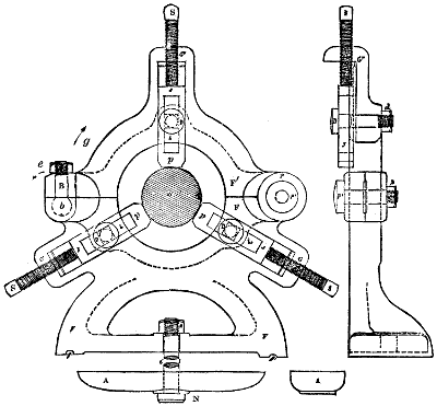
Fig. 802.
When the work is sufficiently long or slender to cause it to sag and bend from its own weight, or bend from the pressure of the cut, it is supported by means of special guides or rests. Fig. 802 represents a steady rest of the ordinary pattern; its construction being as follows:—f is a base fitting to the Vs of the lathe shears at f, and capable of being fastened thereto by the bolt c, nut n, and clamp a. f′ is the top half of the frame, being pivoted at p to f, the bolt p′ forming the pivot for both halves (f and f′), of the frame, which may be secured together by the nut of p′. On the other side of the frame the bolt is pivoted at b to f. This bolt passes through an open slot in f′, so that its nut being loose, it may swing out of the way as denoted by the arrow e, and the top half frame f′ may be swung over in the direction of arrow g, the centre of motion or pivot being on the bolt p′. With f′ out of the way the work may be placed within the frame, the nut of b and also that of p′ may be tightened up so as to lock the two halves of the frame firmly together.
On this frame and forming a part of it are the three ways, g g′ g′′, which contain cavities or slide ways to which are fitted and in which may slide the respective jaws j, and to operate these jaws are the respective square-headed screws s, which are threaded through the tops of the respective ways g, g′, and g′. The screws are operated until the ends of the jaws j have contact with the work w, and hold it axially true with the line of centres of the lathe, or otherwise, as the nature of the work may require. When adjusted the jaws are locked to the frame by means of the bolts d, which are squared to fit in the rectangular openings, shown at h in the respective jaws, so as to prevent the bolts from rotating when their locking nuts d are screwed home.
As an example of the use of this device as a steadying rest, suppose a long shaft to require turning from end to end and to be so slight as to require steadying, then a short piece of the shaft situated somewhat nearer the live centre than the middle of the length of the work is turned upon the work, so that this place shall be round and true to receive the jaws, or plates p, and revolve smoothly in them. The jaws are then adjusted to fit the turned part a close sliding fit, but not a tight fit, as that would cause the jaws to score the work. To prevent this even under a light pressure of contact, oil should be occasionally supplied. This steadies the work at its middle, preventing it from springing or trembling when under the pressure of the cut.
By placing the steady rest to one side of the middle of the work length, at least one half of that length may be turned before reversing the work in the lathe centres. After reversing the work end for end in the lathe centres, the jaws, or plates p, are adjusted to the turned part, and the turning may be completed.
In adjusting the plates p to the work, great care is necessary or they will spring the work out of its normal line of straightness, and cause it to be out of parallel, or to run out of true in the middle of its length, as explained in the remarks referring to the cat head shown in Fig. 809.
The plates p should be gripped to the frame by the nuts with sufficient force to permit them to be moved by the set-screw s under a slight pressure, which will help their proper adjustment. They should also be adjusted to just touch the work, without springing it, the two lower ones being set up to the work first, so that their contact shall serve to relieve the work of its spring or deflection, due to its own weight. This is especially necessary in long slender spindles, in which the deflection may occur to a sensible degree.
If the work does not require turning on its full length, the steady rest may be applied but a short distance from the length of the part to be turned, so as to hold the work more steadily against the pressure of the cuts.
Steady rests are often used to support the end of work without the aid of the dead centre, but it is not altogether suitable for this class of work, because it has no provision to prevent the work from moving endways and becoming loose on the dead centre. A provision of this kind is sometimes made by tying the work driver to the face plate or to the pins driving the work driver or dog, or bolts and plates holding the work driver towards the lathe face plate; but these are all objectionable in that unless the pressure thus exerted be equal, it tends to spring or bend the work.
Another method of preventing this is to drive the work by means of a universal chuck; but this again is objectionable, because the jaws of these chucks do not keep dead true under the wear, and indeed if made to run concentrically true (in cases where the chuck has provision for that purpose) the gripping surfaces of the chuck jaws have more wear at the outer than at the inner ends, hence those surfaces become in time tapering. Again the jaws wear in time so easy a fit in their radial slots that they spring under pressure, and the wear not being equal, the amount of spring is not equal, so that it is impracticable to do dead true work chucked in this way.
The reasons that the chuck jaws do not wear equal in the radial slots may be various, as the more frequent presence of grit in one than in the other, less perfect lubrication, inequalities in the fit, less perfect cleaning, and so on, so that it is not often that the wear is precisely equal. In addition to these considerations there are others rendering the use of the steady rest in some cases objectionable; suppose, for example, a piece of cylindrical work, say 6 feet long, to have in one end a hole of 2 inches diameter, which requires to be very true (as, for example, the cone spindle for a lathe). Now let the face plate end be driven as it may, it will be a difficult matter to set the steady rest so as to hold the other end of the work in perfect line, so that its axial line shall be dead true with the line of lathe centres, because the work will run true though its axial line does not stand true in the lathe.
Here it may be added that it will not materially aid the holding of the work true at the live centre end, by placing it on the live centre and then tightening the universal chuck jaws on it, because the pressure of those jaws will spring it away to some extent from the live centres. This will occur even though the work be placed between the two lathe centres, and held firmly by screwing up the dead centre tight upon the work, before tightening the chuck jaws upon the work, because so soon as the pressure of the dead centre is removed, the work will to some extent relieve its contact with the live one.
If the jaws of the chuck are not hardened, they may be trued up to suit a job of this kind as follows:—A ring (of such a size that when gripped in the outer steps of the chuck jaws, the inner steps will be open to an amount about equal to the diameter of the work at the live centre end) may be fastened in the chuck, and the inner ends of the jaws may be turned up with a turning tool, in which case the jaws will be made true while under pressure, and while in the locations upon the chuck in which they will stand when gripping the work, under which conditions they ought to hold the work fairly upon the live centre. But even in this case the weight of the work will aid to spring it, and relieve it from contact with the live centre.
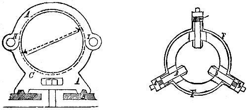
Fig. 803.
Now let us suppose that the piece of work is taper on its external diameter at each end, even truing of the chuck jaws will be of no avail, nor will the steady rest be of avail, if the taper be largest at the dead centre end. Another form of steady rest designed to overcome these objectionable features is shown in Fig. 803. In this case the stand that is bolted to the lathe bed is bored to receive a ring. This ring is made with its middle section of enlarged diameter, as denoted by the dotted circle c. Into the wide part of the stand fits a ring f, its external diameter fitting into c. The ring carries the jaws, hence the ring is passed over the work, and is then inserted into the stand, while the work is placed between the lathe centres.
The ring revolves with the work and has journal bearing in the stand, the enlarged diameter c preventing end motion. There is nothing here to take up the lost motion that would in time ensue from the wear of the radial faces of the ring, hence it is better to use the cone-plate shown in Fig. 805.
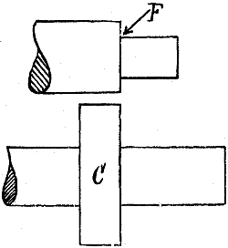
Fig. 804.
When, however, the work will admit of being sufficiently reduced in diameter, it may be turned down, leaving a face f in Fig. 804, that may bear against the radial faces of the jaws of the steady rest; or a collar may be set upon the work as in Fig. 804 at c. But these are merely makeshifts involving extra labor and not producing the best of results, because the radial face is difficult to keep properly lubricated, and the work is apt to become loose on the live centre.
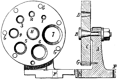
Fig. 805.
For these reasons the cone plate shown in Fig. 805 is employed; a is a standard fitting the shears or bed of the lathe and carrying the circular plate c by means of the stud b, which is fitted so as to just clamp the plate c firmly to the frame a when the nut of b is screwed firmly home with a wrench.
The plate c contains a number of conical holes, 1, 2, 3, &c., (as shown in section at d) of various diameters to suit varying diameters of work.
The frame is fitted to the lathe bed so that the centre stud b stands sufficiently out of the line of lathe centres to bring the centres of the conical holes true with the line of lathe centres. The centres of the conical holes are all concentric to b. Around the outer diameter of the cone plate are arranged taper holes g, so situated with reference to the coned holes that when the pin, shown at g in the sectional view, will pass through the plate and into the frame a as shown, one of the coned holes will stand axially true with the line of lathe centres. Hence it is simply necessary to place one end of the work in the live centre, with a work driver attached in the usual manner; to select a coned hole of suitable size; to move the frame a along the lathe bed until it supports the overhanging end of the work in a suitably sized coned hole without allowing the work any end motion, and to then fasten the frame a to the lathe bed, and the work will be ready to operate on. The advantages of this device are that the pin shown at g in the sectional view holds the conical hole true, and thus saves all need of adjustment and liability to error, nor will the work be sprung out of true, furthermore the tool feed may traverse back and forth, without pulling the work off the live centre. With this device a coarse pitch left-hand internal thread may be cut as easily as if it were an external thread and the work was held between the lathe centres, heavy cuts being taken which would scarcely be practicable in the ordinary form of steady rest.
The pins b and g and the coned holes should be of cast steel hardened, so as to avoid wear as much as possible. The plate may be made of cast iron with hardened steel bushes to fit the coned holes.
It is obvious that the radial face of the work at the cone plate end, as well as the circumference, must be trued up, so that the work end may have equal contact around the bore of the coned rings.
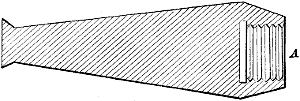
Fig. 806.
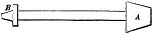
Fig. 807.
Figs. 806 and 807 represent a class of work that it would be very difficult to chuck and operate on without the aid of a cone plate. The former requires to have a left-hand thread cut in its bore a, and the latter a similar thread in end a. A universal chuck cannot be used to drive the work, because in the former case it would damage its thin edge, and in the latter the jaws would force the work out of the chuck; a steady rest cannot be used on the former on account of its being taper, while if used on the latter there would be nothing to prevent the work from moving endwise, unless a collar be improvised on the stem, which on account of the reduced diameter of the stem would require to be made in two halves. It can, however, be driven on the live centre by a driver or dog, and supported at the other end by the cone plate without any trouble, and with an assurance of true work.
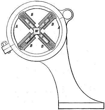
Fig. 808.
Fig. 808 represents a form of steady rest designed by Wm. MacFaul, of the Freeland Tool Works, for taper work. The frame affords journal bearing to a ring a, having four projections b, to which are a close but easy sliding fit, the steadying jaws c. These are held to the work or cue blank w by the spiral springs shown in the projections or sockets b, which act against the ends of c. It will be observed that the work being square could not move in any direction without moving sideways the two of the steadying jaws c which stand at a right angle to that direction. But the jaws c fit the bore of the sockets, and cannot, therefore, move sideways; hence it is evident that the work is firmly supported, although the steadying jaws are capable of expanding or contracting to follow the taper of the blank cue or other piece of work. This enables the steady rest to lead the cutting tool instead of following it, so that the work is steadied on both sides of the tool. Obviously, the stand may be fastened to the leading side of the lathe carriage or fitted upon the cross-slide, as may be most convenient.
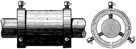
Fig. 809.
To steady work that is unturned and of so great a length that it springs too much to permit of its being turned true, the sleeve or cat head shown in Fig. 809 is employed; it may contain three or four screws c, to true it upon the work. The body b is turned true.
The set-screws are so adjusted upon the work, that the outside runs quite true from end to end. The jaws of the steady rest are then set to just touch the circumference of the sleeve, care being taken that their pressure does not spring the axial line of the work out of its normal straight line. If the shaft is to be turned from end to end, the cat head should be placed sufficiently to one side of the centre of the length of the work and nearer the live centre, that the lathe tool may turn up the work for a distance of at least half its length, or slightly more than half. One half of the work being turned, the shaft is reversed end for end in the lathe, when the cat head may be moved to envelop the turned part, and again set true, or the jaws of the steady rest may be set direct upon the work; in this latter case, however, the friction between the jaws and the work will be apt to leave rings or marks upon the latter.
If the cat head is not set to run quite true upon the work, the latter will not run true when the steady rest is removed, and if the jaws of the steady rest spring the axial line of the work out of its normal straightness, the work will be turned either larger or smaller in diameter in the middle of its length, according to the direction in which the work is sprung.
Suppose, for example, that the work is sprung laterally towards the tool point, then the work will be turned smaller in the middle, or if the work were sprung laterally in the opposite direction, it would be turned larger in the middle than at the ends. If the work is sprung vertically so as to approach or recede from the lathe bed, the amount of the error will be less than if it were sprung laterally, and the nature of the error will depend upon the height of the cutting tool with relation to the work. If, for example, the point is above the centre of the work, and the latter is sprung towards the lathe bed, the work will turn of largest diameter in the middle of its length; or with the tool point placed at the centre of the work, the same result will follow, whether the work be sprung up or down; but if the work be sprung up or away from the lathe bed, and the tool point be placed above the centre, the diameter of the work will be turned smaller than that at the ends.
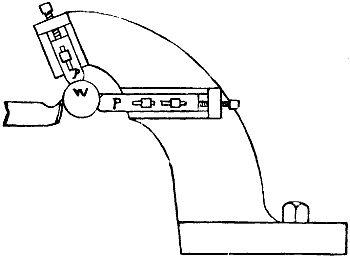
Fig. 810.
When the work is to be turned from end to end or for a considerable distance, a follower rest such as shown in Fig. 810 should be employed, being similar to the steady rest shown in Fig. 802, except that it is open in front, and being fastened to the slide rest carriage, of course travels with the tool; hence the plates p may be either directly in front of the tool or following it, but if the work w has been turned true and parallel, the plates p may be in front of the tool, or rather may lead it.
The follower rest should always be set to the work when as near as practicable to the dead centre, in which case it will be easier to set it without springing the work.
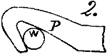
Fig. 811.
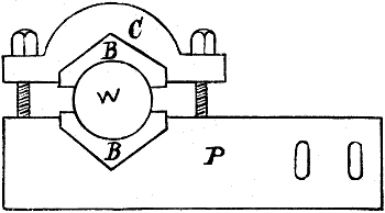
Fig. 812.
For work of small diameter for which the plates p would be too large, and therefore in the way, the plate p, Fig. 811, may be used, being bolted to the follower rest. For work of larger diameter the device shown in Fig. 812 is sometimes used. It consists of a plate p with a cap c, and bolts for holding the bearings b, b. These bearings are bored slightly larger in diameter than the finished diameter of the work.
The advantage of the use of this device is that bearings of the requisite bore having been selected they may be inserted and adjusted a proper fit to the work before p is fastened to the follower rest, thus avoiding the liability of being either too tight or too loose as may happen when the plates cannot be moved or rotated to test the fit. Another and great advantage is that if after the adjustment of the bearings b, b to the work, the plate p is carefully bolted to the follower rest, the liability of springing the work is eliminated, hence truer work will be produced.
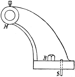
Fig. 813.
A representative of another class of follower rest is shown in Fig. 813, the hub h is accurately bored to receive collars or rings of various diameters of bore to suit the work. The bore of h may be made to stand axially true with the lathe centres, and thus avoid the trouble of setting, by employing the steady pin s, which, being a close fit in the follower rest and in the lathe carriage will bring the rest to its proper distance from the lathe centres, where it may be secured by the bolt b, which may screw into the metal of the carriage or operate to lift a wedge or guide slip so as to grip the V-slide of the carriage and take up any lost motion between the slide in the rest and that in the lathe carriage.
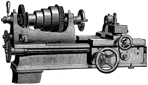
Fig. 814.
Fig. 814 shows a follower rest in position on the cross slide of a lathe.
Chucks and Chucking.
There is a large class of small work that could be held between the lathe centres, but that can be more conveniently held in chucks. Chucks are devices for holding work to the live spindle, and may be divided into classes as follows:
1st. Those in which the work is secured by a simple set-screw.
2nd. Drill chucks, which are applied mainly to drive drills, but which may also be used to drive very small work to be operated upon by cutting tools, the mechanism causing the jaws to move simultaneously to grip or release the work.
3rd. Independent chucks, in which the jaws are operated separately.
4th. Universal chucks, which are larger than drill chucks, and in which the jaws operate simultaneously.
5th. Combination chucks, in which the jaws may be operated either separately or simultaneously as may be required.
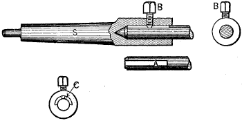
Fig. 815.
Referring to the first, Fig. 815 represents a simple form of set-screw chuck, the stem s fitting into the live centre hole, and the outer end being pierced to receive a drill shank, and the iron from which a piece of work may require to be turned, which is secured in the chuck by the set-screw b. In the case of drill or other cutting tools, however, it is better that they be provided with a flat place a, to receive the set-screw pressure, and enable it to hold them more securely. The objections to this class of chuck are threefold: First, each chuck is suitable for one diameter of work only; secondly the screw head b is in the way; and thirdly, the set-screw pressure is in a direction to set the work out of true, which it will do unless the work is a tight fit to the bore of the chuck. In this case, however, it is troublesome to insert and remove the drill, unless the bore of the socket is relieved on the half circumference nearest to the set-screw, as shown at c in the end view, in which case the efficiency of the chuck is greatly enhanced.
Referring to the second class they are made to contain either two or three jaws.
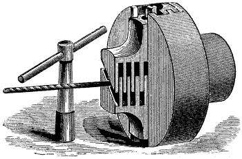
Fig. 816.
When two jaws are employed they are made to slide in one slideway, and are operated therein by a right and left-handed screw, causing them to simultaneously advance or recede from the chuck axis. Fig. 816 represents a chuck of this class, the jaws fitting one into the other to maintain each other in line, and prevent their tilting over from the pressure.
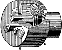
Fig. 817.
In scroll chucks the mechanism for operating the jaws is constructed upon two general principles. The first may be understood from Fig. 817, in which the body of the chuck is provided upon its end face with a scroll c, with which the ends of the jaws a engage. These jaws fit into radial slots in the shell e, which is capable of rotation upon b and is held thereto by the cap d; hence rotating e carries around the jaws a, and the thread c causes them to approach or recede from the chuck axis, according to their direction of rotation.
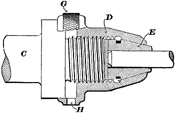
Fig. 818.
The second general principle upon which small drill chucks are constructed may be understood from Fig. 818, in which c may be taken to represent the end of a lathe spindle or a stem fitting into the live centre hole in the same. At the other end it is to receive the shell d which screws upon it. d is coned at the outer end of its bore, and the jaws e are made to fit the cone, and it is obvious that if d be rotated to screw farther upon c, the coned bore of d will act to force the jaws e nearer to the chuck axis and cause them to close upon and grip the work. To operate d it is knurled or milled at g, or it may have pin spanner holes as at h. In this class of chuck it is essential that the direction of rotation of d to close the jaws must be opposite to that in which the drill rotates, otherwise the resistance of the work against the jaws would cause d to rotate upon c, and the work to become released from the jaw grip. Furthermore, as the larger the work the more severe the duty in driving it, it is usually provided by the construction of such chucks that the jaws shall be opened to their maximum when at their nearest approach to the body (as c) of the chuck, and shall close as they move outward or away from the same. This principle of moving the jaws radially by means of a cone sliding upon a cone is applied in numerous ways, thus sometimes the jaws are provided with wings that slide upon a cone or in slide ways that are at an angle to the chuck axis.
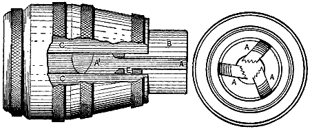
Fig. 819.
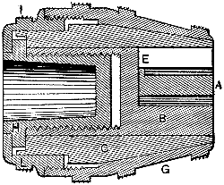
Fig. 820.
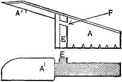
Fig. 821.
Figs. 819, 820, and 821 represent Gage’s patent chuck, in which the gripping surfaces of the jaws are serrated to increase the grip, and to further secure the same object the jaws move at an angle instead of in a radial line, so that the body of the jaws is more directly in the line of strain, and therefore resists it better. The serrations are left-handed, so that the tendency is to force the drill forward and toward the cut, supposing them to act as a nut and screw upon the drill shank. The jaws are supported by the central cylindrical piece that contains them out to the extreme end, and have in addition a lug which slides in radial grooves. Fig. 819 is a side elevation, with a piece of the shell removed to show the jaw and its slide way, and an end view showing the arrangement of the jaws. Fig. 820 is a sectional side elevation, and Fig. 821, two views of the jaws removed from the chuck; a represents the jaws with the lug e to slide in the radial slots provided in b. The wings a′ of the jaws slide in the ways in b, the ways passing through the opening f in Fig. 821; c is the cone for causing the jaws to open and close radially. The driving piece h has a left-hand thread operating in b. It also has a collar abutting over one side against the end of b, and secured on the other by the cap i, which threads into the shell g. A pin in c secures it to the cap i, so that if rotated both move together. On the other hand, if h be rotated and g is held stationary, the thread on h operates on b as a nut, causing it to slide, carrying the jaws with it, and the jaws are simultaneously opened or closed according to the direction of rotation of h. Fig. 819 shows the jaws screwed partly out, and therefore partially closed, while in Fig. 820 the jaws are shown within the chuck, and therefore opened to their fullest extent.
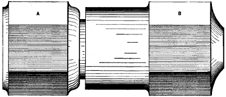
Fig. 822.
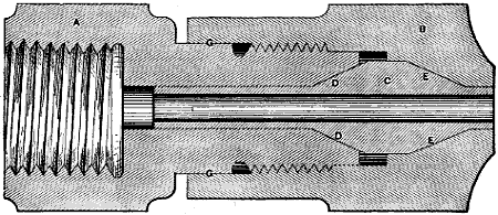
Fig. 823.
Figs. 822 and 823 represent a chuck employed by the Hancock Inspirator Co., of Boston, for very true work. This chuck will not get out of true by wear, and holds brass work against a good lathe-cut without indenting it.
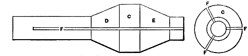
Fig. 824.
Fig. 822 shows the chuck complete. Fig. 823 is a mid-section of chuck complete. Fig. 824 is a side and an end of the work-gripping piece. The chuck is composed of three pieces, a, b and c. Piece a screws upon the lathe spindle and is bored to receive c; piece b screws upon a and receives the outer end of c, which is provided with a double cone d e, and is split nearly its full length at three places, one of which is shown at f, so that when b is screwed upon a the two cones upon a, b compress c, and cause the diameter of its bore to decrease and grip the work. The splits f are made long, so that c shall not close at its outer end only, but on both sides of the cones, and thus grip the work parallel.
There are several advantages in this form of construction; thus the parallel bore of a, in which c fits, is not subject to strain or wear, and therefore remains true and holds c true. Furthermore, b has no tendency to wear out of true, because it fits upon a at the part g, as well as at its threaded end, while the cone e of c also acts to keep it true. As b is screwed up with a wrench fitting its hexagon exterior, the work can be held against any amount of cut that the lathe will drive.
It is obvious that the capacity of the chuck, so far as taking in range of different diameters, is quite limited, but the excellence of its execution far more than compensates for this when work is to be turned out true and correct to standard gauge.
To increase the range of capacity of the chuck, the split piece only needs to be changed. Before hardening the split piece the jaws should be sprung well apart, so that they will spring open when released by unscrewing the outside shell to release the work and insert another piece.
In proportion as the diameter of the work is increased it requires to be more firmly held, and the chucks are made with jaws moved by screws operated by wrench power. These chucks are made with two, three, or four jaws, and the bite of the jaw is shaped to suit the nature of the work, the gripping area being reduced for very small work, and serrated parallel to the chuck axis so as to form gripping teeth for firmly gripping rough work, as shown in some of the following examples:—
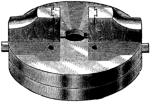
Fig. 825.
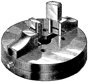
Fig. 826.
Figs. 825 and 826 represent the Horton two-jawed chucks with false or slip jaws, which are removable so that jaws of various shapes in the bore may be fitted to the same chuck, thus enabling the jaws to be varied to suit the shape of the work to be held. The jaws are secured in place by the pins shown.
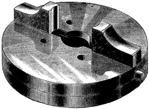
Fig. 827.
Fig. 827 shows a two-jawed solid jaw chuck, the bite of the jaws being made hollow, so as not to mark the surface of the work, while they will hold it very firmly.
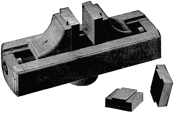
Fig. 828.
In Fig. 828 is shown what is termed a box-body two-jawed chuck, which is mainly used by brass turners. The object of this form of body is to permit the flanges, &c., of castings escaping the face of the chuck.
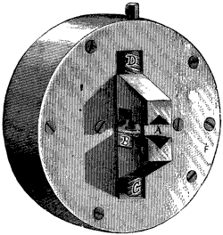
Fig. 829.
Fig. 829 also represents a two-jawed chuck, the body being cylindrical, and having a V-groove at a to receive the work. The screws c, d may act independently of each other, or a continuous screw may be used, having, as in the figure, a left-hand thread at c, and a right-hand one at d, so that the jaws move simultaneously when the screw is operated. The difference between these two methods being as follows:—
When one screw is used the jaws will hold the work so that the centre of rotation will be midway between the points of contact of the jaws of the chuck and the work, hence work cannot be set eccentrically, unless pieces of iron are inserted between it and one of the jaws. When two screws are used the jaws may be operated separately, and one jaw may be set to such distance from the centre of rotation as the necessities of the work may require; but in this case more adjustment is required to set either square or cylindrical work to rotate on its axis than when the jaws operate simultaneously as with a right and left-hand screw. It is obvious that the axial line of the screw or screws must stand parallel with the plane of the face f. It will be observed that the back of each jaw is cut away at b: this serves two purposes, first it permits of a piece of work having a small flange, head or projection being held in the Vs of the jaws; and secondly, it equalizes the wear on the jaws of the chuck, because in jaw chucks generally there is more wear at the outer than at the inner end of the jaws, because work shorter than the length of the jaws, or requiring to be held as far out from the jaws as possible, does not have contact at the back end of the work holding jaw faces, hence the jaws are apt to wear, in course of time, taper. By cutting away the jaws at the back, the tendency to unequal wear is greatly reduced, hence this plan is adopted to a more or less degree in the dogs or jaws of all chucks, being in many cases merely a small recess from 1⁄16 to 1⁄8 inch deep only.
When the jaws have a V-groove as in the cut, the face f of the chuck does not form a guide in setting the work, the truth of the V-grooves being solely relied upon for that purpose.
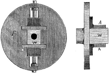
Fig. 830.
The form of two-jawed chuck shown in Fig. 830 is intended for square or rectangular work, and is mainly used by wood workers. It may be operated by a right and left-hand screw, but is generally preferred with independent screws. The face f of the chuck may be employed to serve as a guide in setting the work as shown in the cut, in which w represents a piece of work held between the jaws a, a, and resting against the face f, which therefore serves as a guide against which to set the work to insure that its axial line shall stand parallel with the face f, or in other words at a right angle to the line of centres of the lathe.
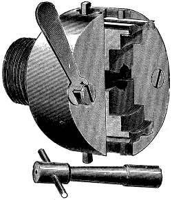
Fig. 831.
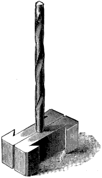
Fig. 832.
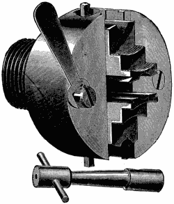
Fig. 833.
In Fig. 831 is an example of a machinist’s two-jawed chuck. The jaws are operated simultaneously by a right and left-hand screw. The jaws are provided with slides to receive the two separate pieces shown in figure, which may be made to suit the form of special work. The two screws shown on each side of the chuck face are to support a piece of work that is too large to be otherwise held firmly by the chuck. These screws may be operated by screw-driver wrench, to enable the face of the work to rest on them, and therefore be supported parallel or true with the chuck face. The jaws may be turned end for end in their slide ways as shown in Fig. 833, to enable them to grip work of small diameter, the separate pieces shown in Fig. 832, being placed on the jaws for such small pieces as drills, &c.
In the larger sizes, lathe chucks are provided with either three or four jaws, which are caused to operate either independently or simultaneously, and in some cases the construction is such that the same chuck may be used as an independent or as a universal one at will, in which case they are termed combination chucks. Concerning the number of jaws it may be observed that a three-jawed chuck will hold the work with an equal pressure on all three jaws, whether it be cylindrical or not, but in a four-jawed chuck the jaws will not have an equal grip upon the work, unless the same be either cylindrically true or square, hence it is obvious that a three-jawed chuck is less liable to wear out of true, and is also preferable for holding unturned cylindrical work, while it is equal to a four-jawed one for true, but unsuitable for square work.
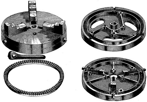
Fig. 834.
Fig. 834 represents the construction of the Horton chuck. Upon the screws that operate the jaws are placed pinions that gear into a circular rack, so that by operating one jaw with a wrench the rack is revolved and the remaining jaws are operated simultaneously. The chuck being constructed in two halves, the rack may be removed and the jaws operated separately, or independently as it is termed.
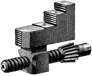
Fig. 835.
Fig. 835 represents one of the jaws with its operating screw and pinion removed from the chuck. The gripping surfaces of the steps in the jaws are serrated to increase their grip upon the work, and the nuts a, a, against which the works rests, are ground true with the face of the chuck. The corner between the faces a and the bite or gripping surfaces of the jaws are recessed so that the work cannot bind in them, but will bed fairly against the faces a, a, which serve to set the work against and hold it true instead of the face of the chuck.
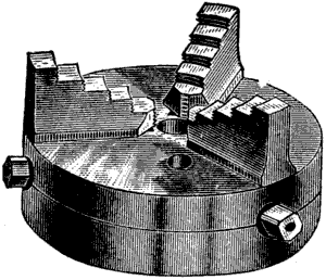
Fig. 836.
Fig. 836 represents a Horton chuck for work up to four inches diameter.
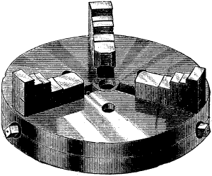
Fig. 837.
Fig. 837 represents a similar chuck for all sizes between 4 and 15 inches, the designated sizes of the chuck being 6, 9, and 12 inches, these diameters being the largest the chucks will take in.
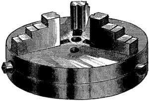
Fig. 838.
Fig. 838 represents a Horton chuck with outside bites for opening out to grip the bores of rings or other hollow work.
The term scroll chuck is applied to universal chucks in which the jaws are operated throughout their full range by means of a scroll thread such as was shown in Fig. 817. The objection to this form is that the threads on the jaws cannot be made to have a full bearing in the scroll thread.
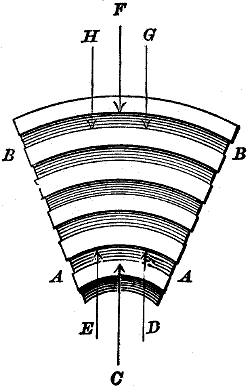
Fig. 839.
In Fig. 839, for example, let a a and b b represent grooves between the scroll threads, and if the thread on the jaws be made to the curve and width of a a, it would not pass in that of b b, and vice-versâ, and it would take but five revolutions of the thread to pass a nut thread from a to b. To overcome this difficulty the jaw threads are not made correct to either curvature but so formed as to fit at points c, d, e, when in the groove a and at points f, g, h, when in groove b. This obviously reduces their bearing area and therefore their durability. To avoid this defect the jaws of many universal chucks are operated by screws in the same way as independent jaw chucks, but provision is made whereby the operation of any one of the jaw screws will simultaneously operate all the others, so that all the jaws are moved by the operation of one screw.
Thus in the following figures is shown the Sweetland chuck.
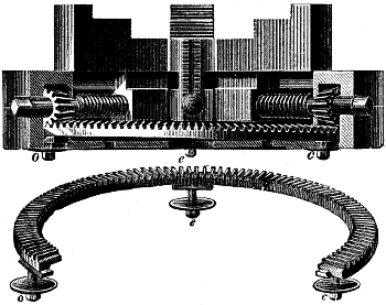
Fig. 840.
Fig. 840 represents the chuck partly cut away to show the mechanism, which consists of a pinion on each jaw screw, and a circular rack beneath. The rack is shown in gear with a pinion at o, and out of gear with a pinion at c, which is effected as follows:—
The rack is stepped, being thicker at its outer diameter, and the thin part forms a recess and the shoulder between the thick and thin part forms a bevel or cone. Between this circular rack and the face of the plate at the back of the chuck is placed, beneath each jaw, a cam block bevelled to correspond with the bevelled edge of the recess in the ring. The cam block stem passes through radial slots in the face of the chuck, so that it can be moved to and from the centre of the chuck. When it is moved in, its cam head passes into the recess in the ring rack, which then falls out of gear with the jaw screw pinion; but when it is moved outward the cam head slides (on account of the bevelled edges) under the ring rack and puts it in gear with the jaw screw pinion. Thus, to change the chuck from an independent one to a universal one all that is necessary is to push out the bolt heads on the cam block stems, the said heads being outside the chuck. The washers beneath these heads are dished to give them elasticity and enable them to steady the cams without undue friction.
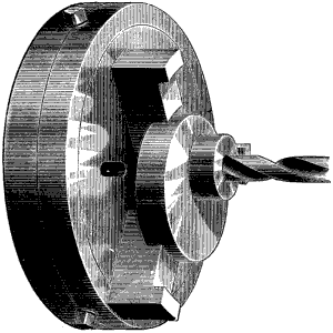
Fig. 841.
To enable the setting of the jaws true for using the chuck as a universal one, after it has been used as an independent one, a ring is marked on the face, and to this ring the edges of all the jaws must be set before operating the cams radially to put the rack ring in gear. In Fig. 841 a three-jawed chuck on this principle is shown acting as an independent one to hold an eccentric. On account of the spring of the parts, which occurs when the strain is transmitted from one part to another, it is desirable when using the chuck as a universal one to first operate one screw to grip the work and then pass to the others and operate them so that they may receive the pressure direct from the screw head and not entirely through the medium of the rack, and there will be found enough movement of the screws when thus operated to effect the object of relieving the rack to some extent from strain.
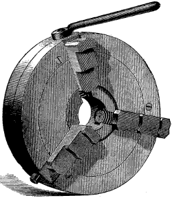
Fig. 842.
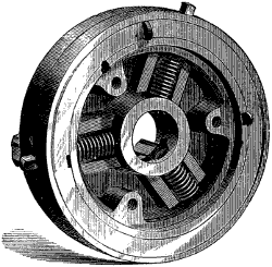
Fig. 843.
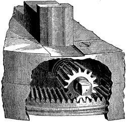
Fig. 844.
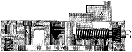
Fig. 845.
Figs. 842, 843, 844, and 845 represent Cushman’s patent combination chuck, in which each jaw may be operated independently by means of its screw thread, or a circular rack may be made to engage with the respective pinions, as shown in Fig. 844, in which case operating any one of the screws operates simultaneously all the jaws. The method of engaging and disengaging is shown in Fig. 845. c represents the circular rack and d a circular ring beneath it. This ring is threaded on its circumference, screwing into the body of the chuck, so that revolving it in one direction moves the circular rack forward and into mesh with the pinions, while revolving it backward causes the rack to recede from the pinions. To operate this ring the lug shown near the top of the chuck in figure is simply pushed in the required direction, while to lock the ring when out of gear with the pinions the spring catch shown on the left of that figure is moved radially. When the rack is in gear, the chuck is a universal one, all the jaws moving simultaneously and equally, whether they be set in such position in their slots as may be necessary to grip an oval or round piece of work; when the rack is out of gear the jaws may be moved by their respective screws so as to run true as for round work, or to hold the work to any degree of eccentricity required.
The jaws may be reversed in their slots and operated simultaneously as a universal chuck, or independently as a simple jaw chuck.
It is obvious that the truth of the jaws for concentricity may be adjusted within the degree of accuracy due to the number of teeth in one pinion divided into the pitch of the jaw operating screw, because each screw may be revolved separately to bring each successive tooth into mesh until the greatest obtainable jaw truth is secured.
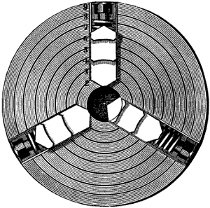
Fig. 846.
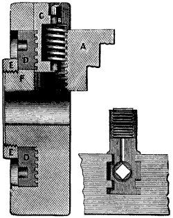
Fig. 847.
Fig. 846 represents a front, and Fig. 847 a sectional view, of the Westcott combination chuck. f is the main body of the chuck screwing on to the lathe spindle. f carries the annular ring d, which has a thread on its face, as shown. d is kept in place by the ring e, which screws in an annular recess provided in the back of the chuck. c is a box fitting in the radial slots of the chuck. The back of the box c meshes into the radial thread on d, hence, when d is revolved, the boxes c move radially in the slots. Now the boxes c afford journal bearing to, and carry the worm or screws b as well as the chuck jaws a, hence revolving d operates the jaws simultaneously and concentrically as in a scroll or universal chuck. By means of the screws b, the jaws may be operated individually (the boxes c and ring d remaining stationary) as in an independent jaw chuck.
Suppose, now, the jaws to have been used independently, and that they require to be set to work simultaneously and concentric to the centre of the chuck, then the screws b may be operated until the jaws at their outer edge are even with the circumference of the chuck (or, if the jaws are nearer the centre of the chuck, they may be set true with a pointer), and the ring d may be operated. In like manner, if a number of pieces of work are eccentric, the screws b may be used to chuck the work to the required eccentricity, and when the next piece is to be chucked the ring d may be operated, and the chuck will be used as a universal one, although the shape of the work be irregular, all that is necessary being to place the same part of the work to the same jaw on each occasion.
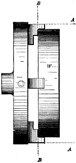
Fig. 848.
The faces of the jaws of jaw chucks when they are true with the face of the chuck (or what is the same thing, run true, and are at a right angle to the axial line of the lathe centres), form guides wherefrom to set the work true, but this will only be the case when they remain true, notwithstanding the pressure of the jaws upon the work. Their truth, however, is often impaired by their wear in the chuck slots which gives them play and permits them to cant over. Thus in Fig. 848 is shown a chuck gripping a piece of work w, and it is obvious that to whatever extent the jaws may spring, or have lost motion in the ways or slots in the chucks, the jaws will move in the direction of the dotted lines a a, the face of the jaw then standing in the direction of dotted lines b b, instead of being parallel to the chuck face. If the spring or wear of the mechanism were equal for each jaw, the work would be held true, notwithstanding that the jaws be out of line, but such is not found to be the case, and as a result the work cannot be set quite true.
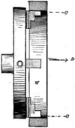
Fig. 849.
When the jaws are applied within the work, as in Fig. 849 (representing the jaws of the chuck within the bore of a ring or piece of work w), the jaws spring in the opposite direction as denoted by dotted lines c, c, and when the jaws are locked to the work the latter moves in the direction of d and away from the chuck face. It will be observed that there is no true surface to put the face of the work against in either case.
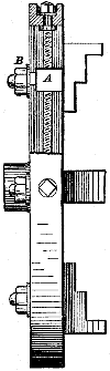
Fig. 850.
This is remedied in independent dog chucks by the construction shown in Fig. 850, in which each jaw has a square a, fitting in the grooves of the chuck, and a nut and washer at b secure the jaw to the face of the chuck so that the lost motion due to wear of the parts may be taken up.
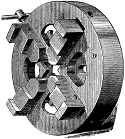
Fig. 851.
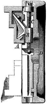
Fig. 852.
The Judson patent chuck is designed to overcome this difficulty, and is constructed as shown in Figs. 851 and 852, the former being a face view and the latter a sectional edge view of the chuck.
The jaws a of the chuck are hollow, and the nut instead of being solid in the jaw is a separate piece, having two wings, the outer of which bears upon a pin in the jaw, while the inner bears upon an inclined surface as plainly shown in the cut, so that the pressure of the screw is distributed equally upon the pin and the inclined surface. The nut b being below the centre of the pin and inclined surface causes the pressure to throw the jaw fair against the face of the chuck, hence the faces of the jaws will serve (equally as well as the surface of the chuck) as a guide to set the work against.
From the short length of gripping surface on the jaws of jaw chucks, they are incapable of holding work of any greater length than, say, about 6 inches, without the aid of the dead centre at the other end of the work; but if the dead centre be used in this way the work will be out of true, unless the jaws of the chuck be quite true, which is not always the case, especially after the chuck has been much in use. Furthermore, it is at times a difficult if not even an impracticable job to set work quite true in this way.
For special work made in quantities the form of the chuck may be varied to conform to the special requirements of the work. The variety of chucks that may thus be formed is obviously as infinite as the variations in form of the work. Thus threaded work may be screwed into threaded chucks, or cylindrical work may be driven into bored blocks forming chucks, or a ring may be chucked and then used as a mandrel to drive the work by friction.
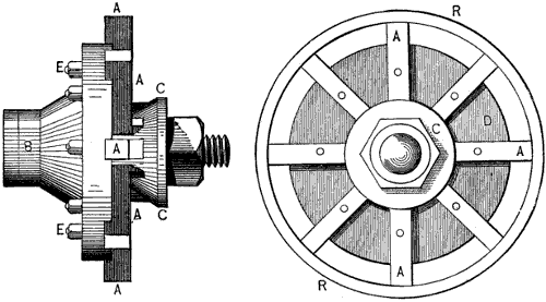
Fig. 853.
An excellent example of special chuck is shown in Fig. 853, representing a chuck for holding piston rings. It resembles a face plate screwing on the live spindle at b, and having 8 radial dogs or jaws a, let into the face d, and secured thereto, when adjusted by the bolts and nuts e. A mandrel is fast in the centre of the chuck carrying the cone c, upon which rest the cone surfaces on the ends of the dogs a, so that screwing up c, by means of the nut shown, throws the dogs a outwards, causing them to grip the inside of the piston ring as shown in the face view of the chuck.
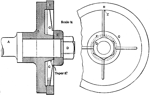
Fig. 854.
In Fig. 854 is shown Swazey’s expanding chuck. b is the body of the chuck driven on an arbor a. The hub of b is turned taper to receive a disc c, which is split partly through in three places, and wholly through at z. By means of the nut and washer d e, the disc is forced up the taper hub and caused to expand in diameter and grip the bore of the work, or ring r, the face of b serving to set the face of the ring against to hold it true sideways.
The chucks employed by wood workers for driving work without, the aid of the back or dead centre of the lathe are as follows:— On account of the fast speed at which the wood-workers’ lathe revolves, it would be undesirable to have their chucks of iron, because of the time it would take the lathe to start them to full speed, and also to stop them after shifting the belt from the driving to the loose pulley of the countershaft, and further because of the damage the tool edges would receive if they accidentally came into contact with the face of the chuck. For these reasons wood workers’ chucks are usually built up upon small iron face plates.
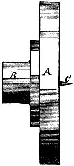
Fig. 855.
Fig. 855 represents a cement chuck, consisting of a disc of hard wood a, screwed firmly to the face plate b; at c is a round steel point located at the axis of the chuck.
This chuck is employed to drive very thin work by the adhesion between the surface of the work and that of the chuck. The surface of the chuck is coated with a mixture of 8 parts of resin to one part of beeswax run into sticks. The chuck is waxed or cemented by rotating it at high velocity while holding the sticks against it. The whole surface of the chuck being thus coated, the centre of the work is forced on the steel point c, and the lathe is kept running until the surface of the work nearly touches that of the chuck, when the belt is passed to the loose pulley overhead and the work forced against the chuck surface until it stops or else revolves the work against the hand pressure, the friction between the surfaces having melted the wax or cement, and cemented the work to the chuck. This leaves the face and the circumference of the work free to be operated upon. The work is removed from the chuck by the gradual insertion between the two of a long thin-bladed knife.
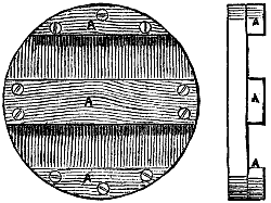
Fig. 856.
For work of large diameter, however, a mere disc of wood will not answer, it being too weak across the grain: and here it may be remarked that the work often supports the chuck, and therefore we should always, in fixing, make the grain of the work cross that of the chuck, because the centrifugal force due to the high velocity is so great that both the chuck and the work have before now been rent asunder by reason of the non-observance of this apparently small matter. When it is considered that the chuck has not sufficient strength across the grain, battens should be screwed on at the back; but a chuck so strengthened will require truing frequently on account of the strains to which its fibres will be subjected from the unequal expansion or contraction of its component parts. Fig. 856 shows the back of a chuck strengthened by the battens a, a, a.
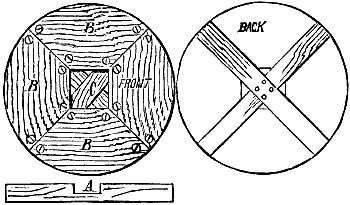
Fig. 857.
Another and superior method of making a chuck suitable for work of about the same diameter is shown in Fig. 857. Its construction enables it to better resist outward strains in every direction, while the strains to which it must necessarily be subject, from variations of temperature and humidity, are less than in the former. It will also be found that it can be trued with greater facility, especially on the diameter, as the turning tool will not be exposed to the end grain of the wood.
The crossed bars at the back of the chuck are half checked, as shown at a, so that both pieces may extend clear across the chuck and not terminate at the centre. They are fastened together at the centre by glue, and also with screws. Upon these bars as a frame, the four pieces composing the body or face of the chuck are fastened by both glue and screws. These pieces need not extend clear to the centre, but may leave an open square as shown, because the centre of a large chuck rarely requires to be used.
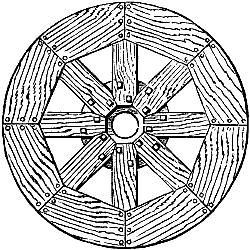
Fig. 858.
For very large chucks a cross of this kind would not afford sufficient strength, hence, the form shown in Fig. 858 is employed. The arms are bolted to an iron face plate, as shown, their number increasing with the diameter of the chuck. To keep the chuck true, the arms should have a level and fair bed upon the face plate, the segments composing the rim being fairly bedded to the arms and well jointed at the ends. They should be both glued and screwed, care being taken that the points of the screws do not meet the face of the chuck, in which case they would damage the turning tools used to true the chuck.
As wooden chucks are liable to warp and become out of true it is requisite to test them on each occasion before use, and true them if necessary. The work is fastened to these chucks by means of screws whose heads are sunk beneath the work surface a sufficient depth so that there is no danger of their coming into contact with the turning tools. In other cases the work is glued to the chuck, a piece of paper being interposed between the work and the chuck, which, by being damped, will enable the more ready removal of the work from the chuck.
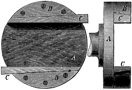
Fig. 859.
Another form of chuck used by wood workers is shown in Fig. 859. It consists of a disc of wood a; screwed to the face plate and carrying the two pieces b, b. The pieces c, c are wedges which slide endways to grip the work. This chuck is especially handy for small work of rectangular form.
From the shape of some work, it cannot be chucked in jaw chucks of any description, and this is especially the case with work of large diameter, hence, large lathes, as, say those that will swing more than three feet, are not usually provided with universal chucks, although sometimes provided with independent jaw-chucks. So likewise in small lathes there are many forms of work that cannot be chucked in jaw chucks, and yet other forms that can be more conveniently held or chucked on face or chuck plates, &c.
If, for example, the surface of the chuck requires to be used in setting the work, the jaws will often be in the way of the tools or instruments employed to set the work. Again, there may be projections on the work which will require the body of the work to be held too far from the face of the chuck to enable its jaws to grip the work.
To meet the requirements of these classes of work chucking devices, which may be classified as follows, are employed:—
1st. Chucking by bolting work to the face plate or chuck plate with bolts and plates.
2nd. Chucking between dogs movable about the face chuck plate, and holding the work from that plate.
3rd. Chucking with the aid of the angle plate, or with the angle plate employed in conjunction with the chuck plate.