Volume 1 — Chapter V.—FASTENING DEVICES. (continued 2)
Reading edition
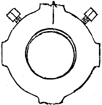
Fig. 469.
If two set screws be used they should both be in the same line (parallel to the shaft axis) or else at a right angle one to the other as in Fig. 469, so that the shaft and bore may drive by frictional contact on the side opposite to the screws. Theoretically the contact of their surface will be at a point only, but on account of the elasticity of the metal the contact will spread around the bore in the arc of a circle, the length of the arc depending upon the closeness of fit between the pulley bore and the shaft. If the bore is a close fit to the shaft it is by reason of the elasticity of the metal relieved of contact pressure on the side on which the set screw or key is to an amount depending upon the closeness of the bore fit, but this will not in a bore or driving fit to the shaft be sufficient to set the wheel out of true.
If two set screws are placed diametrally opposite they will drive by the contact of their ends only, and not by reason of their inducing frictional contact between the bore and the shaft.
A very true method of securing a hub to a shaft is to bore it larger than the shaft and to a taper of one inch to the foot. A bushing is then bored to fit the shaft and turned to the same taper as the hub is turned, but left, say, 1⁄100 inch larger in diameter and 1⁄4 or 3⁄8 longer. The bush is then cut into three pieces and these pieces are driven in the same as keys, but care must be taken to drive them equally to keep the hub true.
Feathers are used under the following conditions:—When the wheel driven by a shaft requires to slide along the shaft during its rotation, in which case the feather is fast in the wheel and the shaft is provided with a keyway or spline (as it is termed when the sliding action takes place), of the necessary length, the sides of the feather being a close but sliding fit in the spline while fixed fast in the wheel.
It is obvious that the feather might extend along the shaft to the requisite distance and the spline or keyway be made in the wheel: but in this case the work is greater, because the shaft would still require grooving to receive the feather, and the feather instead of being the simple width of the wheel would require to be the width of the wheel longer than the traverse of the wheel on the shaft. Nor would this method be any more durable, because the keyway’s bearing length would be equal to the width of the wheel only.
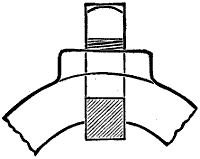
Fig. 470.
When a feather is used to enable the easy movement of a wheel from one position to another a set screw may be used to fix the wheel in position through the medium of the feather as is shown in Fig. 470.
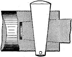
Fig. 471.
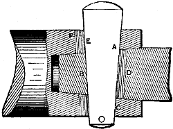
Fig. 472.
Through keys and keyways are employed to lock two pieces, and sometimes to enable the taking up of the wear of the parts. Fig. 471 represents an example in which the key is used to lock a taper shaft end into a socket by means of a key passing through both of them. When the keyway is completely filled by the key as in the figure it is termed a solid key and keyway, indicating that there is no draft to the keyway. Fig. 472 represents a key and keyway having draft. One edge, a c, of the key binds against the socket edges only, and the other edge e binds against the edge b of the enveloped piece or plug, so that by driving in the key with a hammer the two parts are forced together. The space or distance between the edge d and the key, and between edges e and f, is termed the draft. The amount of this draft is made equal to the taper of the key, hence, when the key is driven in so that its head comes level with the socket or work surface, the draft will be all taken up and the key will fill the keyway.
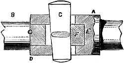
Fig. 473.
Draft is given to ensure all the strain of the key forcing the parts together, to enable the key to be driven in to take up any wear and to adjust movable parts, as straps, journal boxes or brasses, &c. When the bore of the socket and the end of the rod are parallel, the end of the rod f, Fig. 473, should key firmly against the end e of the socket, while the end d of the socket should be clear of the shoulder on the rod; otherwise instead of the key merely compressing the metal at f it will exert a force tending to burst the end f from g of the rod, furthermore, the area of contact at the shoulder d being small the metal would be apt to compress and the key would soon come loose.
In some cases two keys are employed passing through a sleeve, the arrangement being termed a coupling, or a butt coupling.
The usual proportions for this class of key, when the rod ends and socket boxes are parallel, is width of key equals diameter of socket bore, thickness of key equals one-fourth its width, with a taper edgeways of about 1⁄4 inch in 10 inches of length.
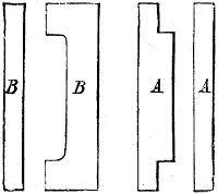
Fig. 474.
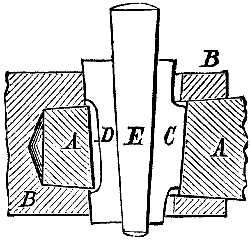
Fig. 475.
As the keys in through keyways often require to be driven in very tight, and as the parts keyed together often remain a long time without being taken apart and in some situations become rusted together, it is often a difficult matter to get them apart. First, it is difficult to drive it out because the blows swell the end of the key so that it cannot pass through the keyway, and secondly, driving the socket off the plug of the two parts keyed together often damages the socket and may bend the rod to which it is keyed. Furthermore, as the diameter of the socket is usually not more than half as much again as the diameter of the plug, misdirected blows are apt to fall upon the rod instead of upon the socket end and damage it. Hence, a piece of copper, of lead, or a block of wood should always be placed against the socket end to receive the hammer blows. To force a plug out of a socket, we may use reverse keys. These are pieces formed as shown in Fig. 474. a, a and b, b are edge and face views respectively of two pieces of metal, formed as shown, which are inserted in the keyway as shown in Fig. 475, in which a is the plug or taper end of a rod and b the socket, c is one and d the other of the reverse keys, while e is a taper key inserted between them, b driving e through the keyway, a and b are forced apart. The action of the reverse keys is simply to reverse the direction of the draft in the keyway so that the pressure due to driving e through the keyway is brought to bear upon the rod end in the part that was previously the draft side of the keyway, and in like manner upon the keyway in the socket on the side that previously served as draft.
Reverse keys are especially serviceable to take off cross heads, piston heads, keyed crank-pins, and parts that are keyed very firmly together.
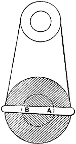
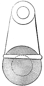
Fig. 476. Fig. 477.
Hubs are sometimes fastened to their shafts by pins passing through both the hub and the shaft. These pieces may be made parallel or taper, but the latter obviously secures the most firmly. If the pin is located as in Fig. 476, its resisting strength is that due to its cross sectional area at a and b. But if the pin be located as in Fig. 477 it secures the hub more firmly, because it draws the bore (on the side opposite to the pin) against the shaft, causing a certain amount of friction, and, furthermore, the area resisting the pressure of the hub is increased, and that pressure is to a certain degree in a crushing as well as a shearing direction.
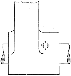
Fig. 478.
If unturned pins are used and the holes are rough or drilled but not reamed, it is better that two sides of the pin should be eased off with a file or on the emery wheel, so that all the locking pressure of the pin shall fall where it is the most important that it should—that is, where it performs locking duty. This is shown in Fig. 478, the hole being round and the pin being very slightly oval (not, of course, so much as shown in the drawing), so that it will bind at a b, and just escape touching at c, d, so that all the pressure of contact is in the direction to bind the hub to the shaft.