Volume 2 — Chapter XXXIII.—FORGING.
Reading edition
Forging.—The operation of forging consists in beating or compressing metal into shape, and may be divided into five classes, viz., hand-forging, drop-forging, machine-forging, forging under trip or steam hammers, and hydraulic forging. In purely hand forging much work is shaped entirely by hand tools, but in large shops much work is roughed out under trip or steam hammers, and finished by hand, while some work is finished under these hammers. In drop forging the work is pressed into shape by dead blows, which compress it into shape in dies or moulds. In machine forging the work is either formed by successive quick blows rather than by a few heavy ones, or in some machines it is compressed by rolling. In hydraulic forging the metal is treated as a plastic material, and is forced into shape by means of great and continuous pressure.
In all forging the nature or quality of the iron is of primary importance; hence the following (which is taken from The English Mechanic), upon testing iron, may not be out of place.
“The English Admiralty and Lloyds’ surveyor’s tests for iron and steel are as follows:—
“Two strips are to be taken from each thickness of plate used for the internal parts of a boiler. One-half of these strips are to be bent cold over a bar, the diameter of which is equal to twice the thickness of the plate. The other half of the strips are to be heated to a cherry-red and cooled in water, and, when cold, bent over a bar with a diameter equal to three times the thickness of the plate—the angle to which they bend without fracture to be noted by the surveyor. Lloyds’ Circular on steel tests states that strips cut from the plate or beam are to be heated to a low cherry-red, and cooled in water at 82° Fahr. The pieces thus treated must stand bending double to a curve equal to not more than three times the thickness of the plate tested. This is severe treatment, and a plate containing a high enough percentage of carbon to cause any tempering is very unlikely to successfully stand the ordeal. Lloyds’ test is a copy of the Admiralty test, and in the Admiralty Circular it is stated that the strips are to be one and a half inches wide, cut in a planing machine with the sharp edges taken off. One and a half inches will generally be found a convenient width for the samples, and the length may be from six to ten inches, according to the thickness of the plate. If possible, the strips, and indeed all specimens for any kind of experimenting, should be planed from the plates, instead of being sheared or punched off. When, however, it is necessary to shear or punch, the piece should be cut large and dressed down to the desired size, so as to remove the injured edges. Strips with rounded edges will bend further without breaking than similar strips with sharp edges, the round edges preventing the appearance of the small initial cracks which generally exhibit themselves when bars with sharp edges are bent cold through any considerable angle. In a homogeneous material like steel these initial cracks are apt to extend and cause sudden fracture, hence the advantage of slightly rounding the corners of bending specimens.
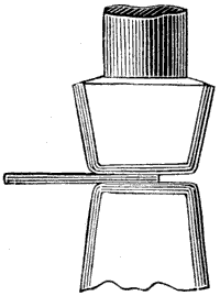
Fig. 2824.
“In heating the sample for tempering it is better to use a plate or bar furnace than a smith’s fire, and care should be taken to prevent unequal heating or burning. Any number of pieces may be placed together in a suitable furnace, and when at a proper heat plunged into a vessel containing water at the required temperature. When quite cold the specimens may be bent at the steam-hammer, or otherwise, and the results noted. The operation of bending may be performed in many different ways; perhaps the best plan, in the absence of any special apparatus for the purpose, is to employ the ordinary smithy steam-hammer. About half the length of the specimen is placed upon the anvil and the hammer-head pressed firmly down upon it, as in Fig. 2824. The exposed half may then be bent down by repeated blows from a fore-hammer, and if this is done with an ordinary amount of care it is quite possible to avoid producing a sharp corner.
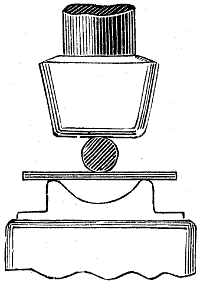
Fig. 2825.
“An improvement upon this is to place a cress on the anvil, as shown at Fig. 2825. The sample is laid upon the cress, and a round bar of a diameter to produce the required curve is pressed down upon it by the hammer-head.
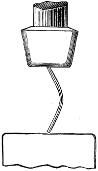
Fig. 2826.
“The further bending of the pieces thus treated is accomplished by placing them endwise upon the anvil-block, as shown in Fig. 2826. If the hammer is heavy enough to do it, the samples should be closed down by simple pressure, without any striking.
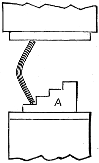
Fig. 2827.
“Fig. 2827 is a sketch of a simple contrivance, by means of which a common punching machine may be converted temporarily into an efficient test-bending apparatus. The punch and bolster are removed, and the stepped cast-iron block a fixed in place of the bolster. When a sample is placed endwise upon one of the lower steps of the block a the descending stroke of the machine will bend the specimen sufficiently to allow of its being advanced to the next higher step, while the machine is at the top of its stroke. The next descent will effect still further bending, and so on till the desired curvature is attained. It would seem an easy matter, and well worth attention, to design some form of machine specially for making bending experiments; but with the exception of a small hydraulic machine, the use of which has, I believe, been abandoned on account of its slowness, nothing of the kind has come under the writer’s notice.
“The shape of a sample after it has been bent to pass Lloyds’ or the Admiralty test is that of a simple bend, the sides being brought parallel. While being bent the external surface becomes greatly elongated, especially at and about the point of the convex side, where the extension is as much even as fifty per cent. This extreme elongation corresponds to the breaking elongation of a tensile sample, and can only take place with a very ductile material. While the stretching is going on at the external surface, the interior surface of the bend is being compressed, and the two strains extend into pieces till they meet in a neutral line, which will be nearer to the concave than to the convex curve with a soft specimen. When a sample breaks, the difference between the portions of the fracture which have been subject to tensile and compressive strains can easily be seen.
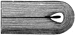
Fig. 2828.
“Fig. 2828 shows a piece of plate folded close together; and this can generally be done with mild steel plates, when the thickness does not exceed half an inch.
“Common iron plates will not, of course, stand anything like the foregoing treatment. Lloyds’ test for iron mast-plates 1⁄2 inch thick, requires the plates to bend cold through an angle of 30° with the grain, and 8° across the grain; the plates to be bent over a slab, the corner of which should be rounded with a radius of 1⁄2 inch.
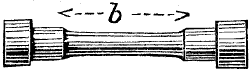
Fig. 2829.
“When the sample of metal to be tested is of considerable thickness, as in the case of bars, it is often turned down in a lathe to the shape shown in Fig. 2829, so as to reduce its strength within the capacity of the machine. The part to be tested has usually a length between the shoulders of 8, 10, or 12 inches, and must be made exactly parallel with a cross-sectional area apportioned to the power of the machine and the strength of the material to be tested. When it is desired to investigate the elastic properties of materials, it is desirable to have the specimens of as great a length as the testing apparatus will accommodate.
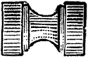
Fig. 2830.

Fig. 2831.
“Many of the early experiments on the tensile strength of wrought iron were made with very short specimens, such as in Fig. 2830, which is a sketch of that used formerly in the royal arsenal at Woolwich. This had no parallel length for extension at all, its smallest diameter occurring at one only point. Mr. Kirkaldy, to whom is due in a great measure the honour of having raised ‘testing’ to an exact science, discovered that this form of specimen gave incorrect results. He found that experiments with such specimens, more especially when the metals were ductile, gave higher breaking strains than were obtained with specimens of equal cross-sectional area having the smallest diameter parallel for some inches of length. This was due to the form of the specimen resisting to some extent the ‘flow’ or alteration of shape which occurs in soft ductile materials previous to fracture. He accordingly commenced to use a specimen of the form shown in Fig. 2831, with a parallel portion for extension of several inches in length, and specimens like that in Fig. 2830 became a thing of the past.
“The specimens shown in the figures admit of being secured in the testing machine in many different ways. But whatever description of holder be employed, two absolute requirements must be kept in view. The holders must be stronger than the sample, and they must transmit the stress in a direction parallel to the axis of the sample without any bending or twisting tendency.
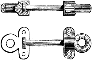
Fig. 2832.
“Fig. 2832 gives two views of a very effective method of holding round specimens, used by Mr. Kirkaldy in his earlier experiments carried out for Messrs. Napier & Sons, of Glasgow. The enlarged ends of the samples are clasped in split sockets provided with eye-holes for attaching them to the shackles of the testing machine, the halves of the sockets being held together during the experiment by small bolts passing through the projecting lugs.
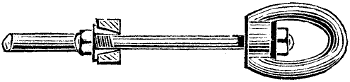
Fig. 2833.
“Fig. 2833 explains the plan adopted for testing the strength of bolts and nuts in the same series of experiments.
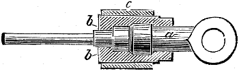
Fig. 2834.
“A good holder for lathe-turned samples is shown in Fig. 2834. Close fitting socket-pieces b b embrace each end of the specimen, and also the turned collar at the extremity of the shackle a. The halves of the socket are held together by a collar c, the interior of which and exterior of the socket rings are turned to an equal taper, so that the socket-pieces are held quite firmly when the collar c is simply slipped over them by hand. When the experiment is over, a few taps with the hammer will remove the collar c.
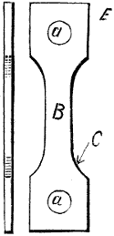
Fig. 2835.
“Samples of plates for tensile testing are usually shaped like Fig. 2835. The parallel portion b is generally 8, 10, or 12 inches long, as in the case of the turned specimens. Two minor points in the preparation of specimens may be here alluded to. In the first place the holes a a must be made large enough to obviate any danger of the pins which are placed in these holes to secure the specimen being sheared in two before the specimen breaks. In the second place, enough material must be left around these pin or bolt holes to prevent the probability of the metal tearing away between the hole and the edge of the plate. The pin holes must be placed exactly in a line with the axis of the specimen, and the part b must be quite parallel in width, so that the strength (and the elongation during the testing) may be, as nearly as possible, equal throughout the length of b. The shoulders, as c, should be easy curves, so that sharp corners may be avoided. When a number of such specimens are required at the same time, the strips of plate may be clamped together and planed or slotted to the desired width as one piece, but the tool marks should be afterwards removed by careful draw-filing.
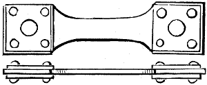
Fig. 2836.
“When the plates are thin, small side pieces are riveted on the sides of the ends to be clamped, as shown in Fig. 2836. These stiffen those ends and afford a larger bearing for the securing pins. The connection with the shackles is made by means of steel pins passing through the end holes, and when specimens like 2835 are properly prepared, the direction of the stress on them must be in a line with their axis. Fig. 2837 shows another form of plate specimen in which the holes are dispensed with, the ends being held in the machine by friction clips, as shown. These specimens are more easily prepared, and from the absence of holes may be made of a very narrow strip of plate.
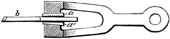
Fig. 2837.
“In Fig. 2837 the jaws or forked arms of the shackle are closed to form a rectangular ring, as shown in section in the figure. Two of the interior faces are tapered inwards to the same angle as the back of the wedges or clips a a′, which are perfectly smooth and free to slide upon the inclined or tapered surfaces of the shackles. The faces of the wedges, however, which come in contact with and grip the specimen to be tested, as b, are fluted or grooved, so that the friction of the edges against the specimen is much greater than against the inside surfaces of the shackles. The result of the arrangement is, that when the shackles are pulled, the wedges a a′ are tightened against the specimen with a degree of force proportionate to the load on the specimen, which is prevented from slipping through the clips by the ‘bite’ of their fluted faces. The grooves on the faces of the clips need not be deep—a depth of a little more than 1⁄16, with about the same distance apart, answering well for ordinary loads. With deep grooves and a wider pitch apart, the danger of the specimen breaking in the clips is increased. The inclination of the backs of the wedges a a′ to the faces may be at an angle of 5 or 6 degrees. When the taper is too small, the removal of the halves of the specimen after breaking is sometimes difficult, while on the other hand, when too great, the specimen is apt to slip between the wedges while being tested. The wedges exert a very considerable outward pressure, and the jaws of the shackles must be made strong enough to resist any strain likely, under extreme conditions, to fall on them, otherwise they will speedily become unfit for use. In securing a specimen care must be taken that its axis is in the direct line of strain, and the opposite clips should be driven in equally so that the stress may act fairly upon it. Parallel planed strips of metal, without any enlargement at the ends, may be tested in these friction clips, though, of course, there is a chance of the specimen breaking within them. Turned specimens may also be held by such clips; as also may rough, unturned round and square bars, an advantage when it is desired to immediately ascertain approximately the strength of metal samples.”
Open fires for hand forging purposes are mainly of two classes, those having a side and those with a bottom or vertical blast.
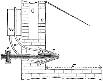
Fig. 2838.
Fig. 2838 represents a side draft forge. f is the fireplace, usually from 3 to 5 feet long, t is the tuyère through which the blast enters the fire, b being the blast pipe. To prevent t from being burned away it is hollow as at s, and two pipes p and p′ connect to the water-tank w, thus maintaining a circulation of water through s; v is simply a valve or damper to shut off the supply of air from the tuyère; d is the opening to the chimney c.
The side blast, though not so much used as in former years, is still preferred by many skilful mechanics, on the ground that it will give a cleaner fire with less trouble. The method of accomplishing this is to dig out a hole in the fire bed and fill it in with coked coal, which will form a drain through which the slag or clinker may sink, instead of remaining in the active fire and obstructing the blast.
In cases where the fire requires to be built farther out from the chimney wall than the location of the tuyère permits, it may be built out as follows:—
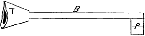
Fig. 2839.
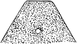
Fig. 2840.
A bar b, Fig. 2839, is placed in the tuyère hole and supported at the other end at p. The coal is well wetted and packed around and above the bar, which is then pulled out endwise, leaving a blast hole through the coal, as is shown in the end view Fig. 2840.
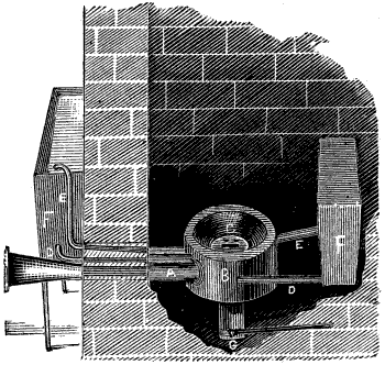
Fig. 2841.
Fig. 2841 represents a patent tuyère of vertical or bottom draft, in which the blast passes through pipe a and circulates around b, finding egress at c into the fire. c is hollow and receives water from the tank f by the pipe d. The steam generated in the nozzle c is conveyed to the tanks by the pipe e.
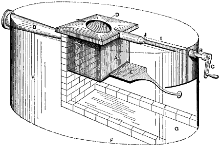
Fig. 2842.
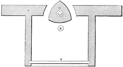
Fig. 2843.
Figs. 2842 and 2843 represent a blacksmith’s forge, for work up to and about 4 inches in diameter. It consists of a wind-box a, supported on brickwork which forms an ash-pit g beneath it. To this box is bolted the wind-pipe b, and at its bottom is the slide e. In an orifice at the top of a is a triangular and oval breaker d, connected to a rod operated by the handle c. This rod is protected from the filling which is placed between the brickwork and the shell f of the forge by being encased in an iron pipe i. The blast passes up around the triangular oval piece d. The operation is as follows: when d is rotated, it breaks up the fire and the dirt falls down into the wind-box, cleaning the fire while the heat is on. At any time after a heat the slide e may be pulled out, letting the slag and dirt fall into the ash-pit beneath. It is a great advantage to be able to clean the fire while a heat is on without disturbing the heat.
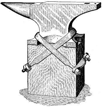
Fig. 2844.
Blacksmiths’ anvils are either of wrought iron steel faced, or of cast iron steel faced, the faces being hardened. It is sometimes fastened to the block by spikes driven in around the edges. A better plan, however, is to make the block the same size as the anvil, and secure the latter by two bands of iron and straps, as shown in Fig. 2844, because in this way the block will not come in the way of arms or projecting pieces that hang below the anvil. The square hole is for receiving the stems of swages, fullers, &c., and for placing work over to punch holes through it, and the round is used for punching small holes.
The proper shape for blacksmiths’ tongs depends upon whether they are to be used upon work of a uniform size and shape, or upon general work. In the first case, the tongs may be formed to exactly suit the special work. In the second case, they must be formed to suit as wide a range of work as convenient.
Suppose, for example, the tongs are for use on a special size and shape of metal only; then they should be formed so that the jaws will grip the work evenly all along, and therefore be straight along the gripping surface. It will be readily perceived, however, that if such tongs were put upon a piece of work of greater thickness, they would grip it at the inner end only, and it would be impossible to hold the work steady. The end of the work would act as a pivot, and the part on the anvil would move about. It is better, therefore, for general work to curve the jaws, putting the work sufficiently within the jaws to meet them at the back of the jaw, when the end will also grip the work. By putting the work more or less within the tongs, according to its thickness, contact at the end of the work and at the point of the tongs may be secured in one pair of tongs over a wider range of thickness of work than would otherwise be the case. This applies to tongs for round or other work equally as well as to flat or square work.
To maintain the jaw pressure of the tongs upon the work, a ring is employed, the tong ends being curved to prevent the ring from slipping off.
After a piece of work has left the fire it should, if there are scales adhering upon it, have them cleaned off before being forged, for which purpose the hammer head or an old file is used, otherwise the forging will not be smooth, and the scale will be hammered into the surface. This will render the forging very hard to operate upon by steel cutting tools, and cause them to dull rapidly. For the same reason it is proper to heat a finished forging to a low red heat and pass a file over its surface, which will leave the forging soft as well as free from scale. A forging should not be finally finished by being swaged or forged after it has become black hot, because it produces a surface tension that throws the work out of true as the metal is cut away in finishing it.
Work to be drawn out is treated according to the amount of elongation and reduction of diameter required. Thus, suppose a piece of square work to require to be drawn out, then it is hammered on its respective sides, being turned upon the anvil so that each successive side shall receive the hammer blows. It is essential, however, that the piece be forged square, or in other words, that during the forging the sides be kept at a right angle one to the other, or else the work will hammer hollow, as it is termed; that is to say, the iron will split at the centre of the bar, which occurs from its being forged diamond-shaped instead of square. If a piece required to be forged diamond-shaped, it must be forged square until reduced to such dimensions as will leave sufficient to draw out while altering its form from the square to the diamond-shape.
In very small work, which is more apt to hammer hollow than large work, the end of the piece is left of enlarged size, as shown in the figure, the strength of the enlarged end serving to prevent the hammering hollow, which usually begins at the end of the piece; the end is in this case forged last. In the case of round work the same rule holds good, inasmuch as that a round bar may be forged smaller to some extent, either by hammer blows or by swaging, but if the forging by hammer blows be excessive, hammering hollow is liable to ensue.
The blacksmith’s set of chisels consists of a hot chisel for cutting off hot iron, a cold chisel for cutting cold metal, a hardy, which sets in the square hole in the anvil, C-chisels, which are curved somewhat like the carpenter’s gouge, and a cornering or V-chisel, in which the cutting edges are at a right angle one to the other.
The hot chisel has its edge well curved in its length, and is kept cool by lifting it from the work after each hammer blow, and by occasionally dipping it in water. Lifting it also prevents it from wedging in the work. The cold chisel is tempered to a blue, and answers virtually to the machinist’s chisel. The hardy is used for small work, which is laid upon it and struck with the hammer. The C-chisel is used, not only in curved corners, but also to cut off deep cuts, answering, like the cape or cross-cut chisel of the machinist, to relieve the corners of the hot chisel. The cornering chisel is used for square corners, situated so that the hot chisel cannot be used. The blacksmith’s punch is made well taper, so that it shall not wedge in the hole it produces.
For large holes a small punch is first used, and the hole enlarged in diameter by driving in punches of larger diameter. If this swells the work at the sides, it is forged down while the punch is in the hole.
The first blow given to the punch is a light one, so as to leave an indentation that will mark the location, and enable its easy correction if necessary. The blows delivered after the correct location is indented are quick and heavy; but a piece of soft coal is inserted and the punch placed on top of it, the gases formed by the combustion of the coal serving to prevent the punch from binding in the hole. Between the blows the blacksmith lifts the punch and moves the handle part of a lateral rotation, which prevents it from becoming fast in the hole. The punch should not be suffered to get red hot, but must be removed and cooled, a fresh piece of green soft coal being inserted in the hole just previous to the punch. If the punch is allowed to become as heated as the work, the end will “upset” or swell and become firmly locked. Should the punch lock in the hole a few blows will usually loosen it, but in extreme cases it is sometimes necessary to employ another punch from the opposite side of the work. Unless in very thin work, the hole is punched half way from each side, because by that means a short stout punch may be used.
It is obvious that when the hole requires to be bell-mouthed or of any other form, the punch must be made to correspond.
The tools employed by the blacksmith, other than tongs, hammers, chisels, and punches, are composed mainly of “fullers” and “swages” of various kinds. The fuller is essentially a spreading tool, while the swage may be termed essentially a shaping one.
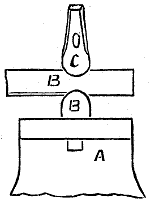
Fig. 2845.
In Fig. 2845, for example, let a represent an end view of an anvil, b the bottom, and c the top fuller, and the effects of blows upon c will be mainly to stretch the piece in the direction of its length without swelling it out sideways.
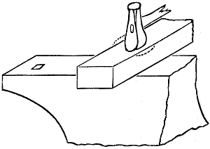
Fig. 2846.
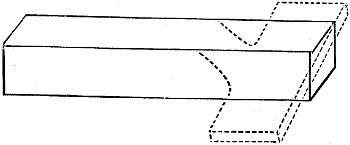
Fig. 2847.
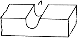
Fig. 2848.
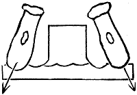
Fig. 2849.
If the work requires to be swelled sideways we turn the fuller the other way around, as in Fig. 2846, in which it is supposed that one side of the work is to be kept flat, hence no bottom fuller is employed. The action of a fuller may be increased in the required direction by leaning in the direction in which we desire to drive the iron; thus, suppose we require to spread the end of a rectangular bar from the full lines to the dotted ones in Fig. 2847 and the first fuller across the piece as at a, Fig. 2848, and then spread out the end by fullering, as in Fig. 2849, inclining the fuller in the direction in which we desire to forge the iron.
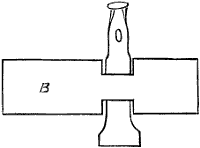
Fig. 2850.
It is the roundness of the face of the fuller that serves to control the direction in which it will drive the iron, since the curve acts somewhat on the principle of a wedge. Suppose, for example, that the faces were flat, as in Fig. 2850, and the iron would spread in both directions, the same as though the hammer were used direct, and if the work were intended to be kept parallel it would frequently require to be turned on edge to forge down the bulge that would form on the edge.
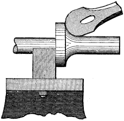
Fig. 2851.
Fullers are, however, also used as finishing tools for curves or corners, an example being given in Fig. 2851, which represents a fuller applied to finish the round corner of a collar.
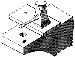
Fig. 2852.
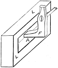
Fig. 2853.
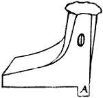
Fig. 2854.
For finishing plane surfaces the flatter shown in Fig. 2852 is employed, w representing the work. For inside surfaces the flatter requires to be offset, as in Fig. 2853, in which l represents a link whose face a may be flattened by the flatter f. There is a tendency in this case for the flatter to tip or cant; and to avoid this and regulate the flatter upon the work, a side foot is sometimes added, as at a in Fig. 2854.
Swages are shaped according to the kind of work they are to be used for.
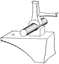
Fig. 2855.
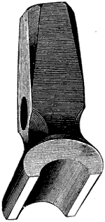
Fig. 2856.
Fig. 2855, for example, represents a top and bottom swage for rounding up iron. For general work the recesses or seats of such swages would be made considerably oval, as in Fig. 2856, the work being revolved slightly after each blow. This capacitates one swage for different sizes of iron. When, however, a swage is to be used for one particular size only, its cavity may be made more nearly a true half circle and may envelop one half the diameter of the work, so that when the top and bottom swages meet, the work will be known to be of the required diameter without measuring it. If the seat were made a true half circle it would lock upon the work, preventing the smith from revolving it and making it difficult to remove the swage.
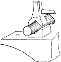
Fig. 2857.
If the conditions are such that a swage must be used to perform forging rather than finishing, its seat should be V-shaped and not curved. Suppose, for example, that a piece of iron, say, 6 inches in diameter, required a short section to be forged down to a diameter of 3 inches, then the swages should be formed as in Fig. 2857, because otherwise the effects of the blow will act to a certain extent to force the iron out sideways, for reasons which will be explained presently.
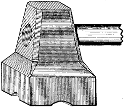
Fig. 2858.
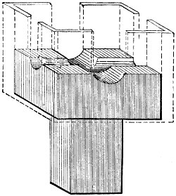
Fig. 2859.
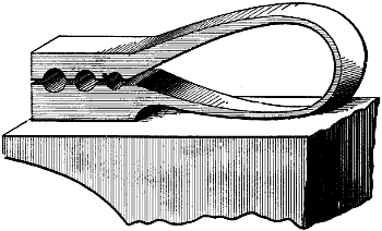
Fig. 2860.
In some cases, for small work, the upper swage is guided by the lower one: thus, in Fig. 2858 is a swage for a cross piece, and the outside of its base is squared and fits easily within the upper part of the lower one shown in Fig. 2859. For very small work, on which the hand hammer is sufficiently heavy to perform the swaging, a spring swage may be use: thus, in Fig. 2860 is a swage for pieces of 3⁄8, 5⁄16, and 1⁄4 inch in diameter, and having a square stem fitting into the square hole in the anvil. Fig. 2861 represents a spring swage for a pin having a collar, and it may be observed that the recess to form the collar must be tapered narrowest at the bottom, so that the top swage will readily release itself by the force of the spring, and so that the work may easily be revolved in the lower one. A similar tool is shown in Fig. 2862, designed for punching sheet metal cold, the die d being changeable for different sizes of punches p.
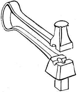
Fig. 2861.
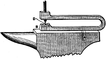
Fig. 2862.
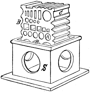
Fig. 2863.
For large hand-made forgings the swage block, such as in Fig. 2863, is employed, s representing a stand for the block, whose dimensions are larger than the block, so that the latter may be rested on its face in the stand when the holes are to be used.
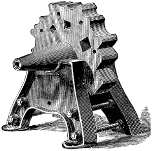
Fig. 2864.
Fig. 2864 represents a swage block mounted on bearers, so that it may be revolved to bring the necessary cavity uppermost.
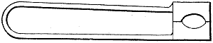
Fig. 2865.
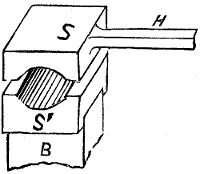
Fig. 2866.
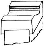
Fig. 2867.
Swages for trip hammers or for small steam hammers are for work not exceeding about 4 inches in diameter, made as in Fig. 2865, the weight of the top swage being sufficient to keep the two closed as in the figure; for larger sizes the bottom swage fits to the anvil, and the top one is provided with a handle, as in Fig. 2866, b representing the anvil block, s′ the bottom, and s the top swage, having a handle h. The flange of the bottom swage is placed as in Fig. 2867, so as to prevent the swage from moving off the anvil block when the work is pushed through it endways. Obviously such swages are employed when the part to be swaged is less in length than the width of the hammer or of the anvil face.
VOL. II. EXAMPLES IN STEAM HAMMER WORK. PLATE XV.
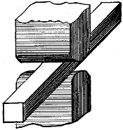
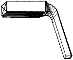
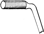
Fig. 2868. Fig. 2869. Fig. 2870.
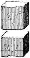
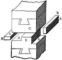
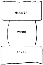
Fig. 2871. Fig. 2872. Fig. 2873.
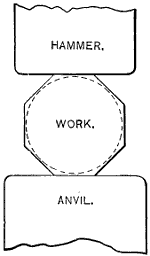
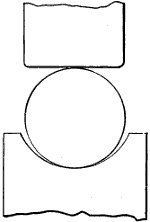
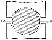
Fig. 2874. Fig. 2875. Fig. 2876.
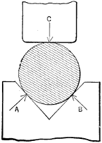
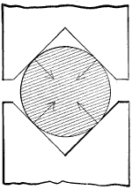
Fig. 2877. Fig. 2878.
If the hammer and anvil face is rounded as in Fig. 2868, or if dies thus shaped are placed in them, their action will be the same as that of the fuller, drawing the work out lengthways, with a minimum of effect in spreading it out sideways.
Detached fullers, such as shown in Figs. 2869 and 2870, are, however, used when the section to be acted upon is less in length than the hammer face.
In the case of trip hammers, steam hammers, &c., blocks fitted to the hammer and anvil block may take the place of detached swages and fullers. Thus, in Fig. 2871 is represented the hammer and anvil block for flat work, the corners being made rounded, because if left sharp they would leave marks on the work. The blocks or dies a and b are dovetailed into their places, and secured by keys k; hence they may be removed, and dies of other shapes substituted.
When the work is parallel it may be forged to its finished dimensions by forming in the lower die recesses whose depth equals the required dimensions. Thus, in Fig. 2872 the recess a in the lower die equals in depth the depth a of the work, while the depth of the recess b in the die equals the thickness of the bar; hence by passing the work successively from a to b, and turning it over a quarter turn, it will be made to finished size, when the faces c d of the dies meet.
For this class of work the recesses must obviously be made in the lower die, because it would be difficult to hold the work upon the lower die in the proper position to meet a recess cut in the upper one: and, furthermore, the recesses in the die should be wider than the work, to avoid the necessity of holding the work exactly straight in the recess, and keeping it against the shoulder or vertical face of the recess. If, however, the work is to be made taper, we may obviously make the recess taper, so as to produce smooth work, the die recess being made to be of the correct depth for the smallest end of the work.
When the shape of the work is such that it cannot be moved upon the die during the forging, the operation is termed stamping, or if the hammer or upper die falls of its own weight it is termed drop forging, and in this case the finishing dies are made the exact shape of the work, care being taken to let the work be enveloped as much as possible by the bottom die, so that the top one shall not lift it out on its up stroke.
In forging large pieces from square to round we have several important considerations. In order to keep the middle of the work sound, it must be drawn square to as near as possible the required diameter before the finishing is begun. During this drawing-down process the blows are heavy and the tendency of the work is to spread out at the sides, as in Fig. 2873.
When the work is ready to be rounded up it is first drawn to an octagon, as shown in Fig. 2874, so as to bring it nearer the work, nearer to cylindrical form. The corners are then again hammered down, giving the work sixteen sides, the work during this part of the process being moved endways, as each corner is hammered down. The blows are during this part of the forging lighter, but still the tendency is to spread the work out sideways. The final finishing to cylindrical form is done with light blows, the work being revolved upon the anvil without being moved endways, so that a length equal to the width of the anvil is finished before the work is moved endways to finish a further part of the length. The tendency to spread sideways is here unchecked, because the iron is squeezed top and bottom only. We may check it to some extent, however, by employing a bottom swage block, as in Fig. 2875, in which case the contact of the swage and the work will extend further around the work circumference than would be the case with a flat anvil. If we were to use a top and a bottom swage, as in Fig. 2876, the circumferential surface receiving the force of the blow will be still further increased, but there will still be a tendency to spread at the sides, as at a b, in Fig. 2876. A better plan, therefore, is to use a V-block with the hammer, as in Fig. 2877, in which case the effects of the blow are felt at a, b, and c, and the points a b of resistance being brought higher up on the work, its tendency to spread is obviously diminished. By using a top and bottom V-block, as shown in Fig. 2878, the effect will be to drive the metal towards the centre, and, therefore, to keep it sound at the centre, it being found that if the metal is swaged much without means being taken to prevent spreading, it “hammers hollow,” as it is termed, or in other words, splits at its centre.
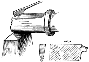
Fig. 2879.
The points a b of resistance to the blow at c are higher and the tendency to spread sideways is better resisted. For cutting off under the steam hammer, the hack shown in Fig. 2879 is used, being simply a wedge with an iron handle.
Welding.—In the welding operations of the blacksmith there are points demanding special attention: first, to raise the temperature of the metal to a proper heat; second, to let the temperature be as nearly equal as practicable all through the mass; third, to have the surfaces to be welded as clean and free from oxidation as possible; fourth, have the parts to be welded of sufficient diameter or dimensions to permit of the welded joint being well forged.
The following remarks on the theory of welding are from a paper read by Alexander L. Holley before the American Institute of Mining Engineers:—
“The generally received theory of welding is that it is merely pressing the molecules of metal into contact, or rather into such proximity as they have in the other parts of the bar. Up to this point there can hardly be any difference of opinion, but here uncertainty begins. What impairs or prevents welding? Is it merely the interposition of foreign substances between the molecules of iron, or of iron and any other substance which will enter into molecular relations or vibrations with iron? Is it merely the mechanical preventing of contact between molecules, by the interposition of substances? This theory is based on such facts as the following:
“1. Not only iron but steel has been so perfectly united that the seam could not be discovered, and that the strength was as great as it was at any point, by accurately planing and thoroughly smoothing and cleaning the surfaces, binding the two pieces together, subjecting them to a welding heat, and pressing them together by a very few hammer blows. But when a thin film of oxide of iron was placed between similar smooth surfaces, a weld could not be effected.
“2. Heterogeneous steel scrap, having a much larger variation in composition than these irons have, when placed in a box composed of wrought-iron side and end pieces laid together, is (on a commercial scale) heated to the high temperature which the wrought-iron will stand, and then rolled into bars which are more homogeneous than ordinary wrought iron. The wrought-iron box so settles together as the heat increases that it nearly excludes the oxidizing atmosphere of the furnace, and no film of oxide of iron is interposed between the surfaces. At the same time the enclosed and more fusible steel is partially melted, so that the impurities are partly forced out and partly diffused throughout the mass by the rolling.
“The other theory is that the molecular motions of the iron are changed by the presence of certain impurities, such as copper and carbon, in such a manner that welding cannot occur, or is greatly impaired. In favor of this theory it may be claimed that, say, 2 per cent. of copper will almost prevent a weld, while, if the interposition theory were true, this copper could only weaken the weld 2 per cent., as it could only cover 2 per cent. of the surfaces of the molecules to be united. It is also stated that 1 per cent. of carbon greatly impairs welding power, while the mere interposition of carbon should only reduce it 1 per cent. On the other hand, it may be claimed that in the perfect welding due to the fusion of cast iron, the interposition of 10 or even 20 per cent. of impurities, such as carbon, silicon, and copper, does not affect the strength of the mass as much as 1 or 2 per cent. of carbon or copper affects the strength of a weld made at a plastic instead of a fluid heat. It is also true that high tool steel, containing 11⁄2 per cent. of carbon is much stronger throughout its mass, all of which has been welded by fusion, than it would be if it had less carbon. Hence copper and carbon cannot impair the welding power of iron in any greater degree than by their interposition, provided the welding has the benefit of that perfect mobility which is due to the fusion. The similar effect of partial fusion of steel in a wrought-iron box has already been mentioned. The inference is, that imperfect welding is not the result of a change in molecular motions due to impurities, but of imperfect mobility of the mass—of not giving the molecules a chance to get together.
“Should it be suggested that the temperature of fusion, as compared with that of plasticity, may so change chemical affinities as to account for the different degrees of welding power, it may be answered that the temperature of fusion in one kind of iron is lower than that of plasticity in another, and that as the welding and melting points of iron are largely due to the carbon they contain, such an impurity as copper, for instance, ought, on this theory, to impair welding in some cases and not to affect it in others.
“The obvious conclusions are: 1st. That any wrought iron, of whatever ordinary composition, may be welded to itself in an oxidizing atmosphere at a certain temperature, which may differ very largely from that one which is vaguely known as ‘a welding heat.’ 2nd. That in a non-oxidizing atmosphere heterogeneous irons, however impure, may be soundly welded at indefinitely high temperatures.
“The next inference would be that by increasing temperature we chiefly improve the quality of welding. If temperature is increased to fusion, welding is practically perfect; if to plasticity and mobility of surfaces, welding should be nearly perfect. Then how does it sometimes occur that the more irons are heated the worse they weld?
“1. Not by reason of mere temperature, for a heat almost to dissociation will fuse wrought iron into a homogeneous mass.
“2. Probably by reason of oxidation, which, in a smith’s fire especially, necessarily increases as the temperature increases. Even in a gas furnace a very hot flame is usually an oxidizing flame. The oxide of iron forms a dividing film between the surfaces to be joined, while the slight interposition of the same oxide, when diffused throughout the mass by fusion or partial fusion, hardly affects welding. It is true that the contained slag, or the artificial flux, becomes more fluid as the temperature rises, and thus tends to wash away the oxide from the surfaces; but inasmuch as any iron with any welding flux can be oxidized till it scintillates, the value of a high heat in liquefying the slag is more than balanced by its damage in burning the iron.
“But it still remains to be explained why some irons weld at a higher temperature than others; notably, white irons high in carbon, or in some other impurities, can only be welded soundly by ordinary processes at low heats. It can only be said that these impurities, as far as we are aware, increase the fusibility of iron, and that in an oxidizing flame oxidation becomes more excessive as the point of fusion approaches. Welding demands a certain condition of plasticity of surface; if this condition is not reached, welding fails for want of contact due to mobility; if it is exceeded, welding fails for want of contact due to excessive oxidation. The temperature of this certain condition of plasticity varies with all the different compositions of irons. Hence, while it may be true that heterogeneous irons, which have different welding points, cannot be soundly welded to one another in an oxidizing flame, it is not yet proved, nor is it probable, that homogeneous irons cannot be welded together, whatever their composition, even in an oxidizing flame. A collateral proof of this is, that one smith can weld irons and steels which another smith cannot weld at all, by means of a skilful selection of fluxes and a nice variation of temperatures.
“To recapitulate. It is certain that perfect welds are made by means of perfect contact due to fusion, and that nearly perfect welds are made by means of such contact as may be got by partial fusion in a non-oxidizing atmosphere or by the mechanical fitting of surfaces, whatever the composition of the iron may be within all known limits. While high temperature is thus the first cause of that mobility which promotes welding, it is also the cause, in an oxidizing atmosphere, of that ‘burning’ which injures both the weld and the iron. Hence, welding in an oxidizing atmosphere must be done at a heat which gives a compromise between imperfect contact due to want of mobility on the one hand, and imperfect contact due to oxidation on the other hand. This heat varies with each different composition of irons. It varies because these compositions change the fusing points of irons, and hence their points of excessive oxidation. Hence, while ingredients such as carbon, phosphorus, copper, &c., positively do not prevent welding under fusion, or in a non-oxidizing atmosphere, it is probable that they impair it in an oxidizing atmosphere, not directly, but only by changing the susceptibility of the iron to oxidation.”
In welding steel to iron both are heated to as high a temperature as possible without burning, and a welding compound or flux of some kind is used.
In welding steel to steel the greatest care is necessary to obtain as great a heat as possible without burning, and to keep the surfaces clean.
An excellent welding compound is composed as follows: Copperas 2 ozs., salt 4 ozs., white sand 4 lbs., the whole to be mixed and thrown upon the heat, as is done when using white sand as described for welding iron. An equally good compound is made up of equal quantities of borax and pulverized glass, well wetted with alcohol, and heated to a red heat in a crucible. Pulverize when cool, and apply as in the case of sand only.
A welding compound for cast steel given by Mr. Rust in the Revue Industrielle is made up as follows: 61 parts of borax, 20 parts of sal-ammoniac, 163⁄4 parts of ferrocyanide, and 5 parts of colophonium. He states that with the acid of this compound cast steel may be welded at a yellow red heat, or at a temperature between the yellow, red, and white heats. The borax and sal-ammoniac are powdered, mixed, and slowly heated until they melt. The heating is continued until the strong odor of ammonia ceases almost entirely, a small quantity of water being added to make up for that lost by evaporation. The powdered ferrocyanide is then added, together with the colophonium, and the heating is continued until a slight smell of cyanogen is noticed. The mixture is allowed to cool by spreading it out in a thin layer.

Fig. 2880.

Fig. 2881.
The lap weld is formed as follows: Suppose it is required to weld together the ends of two cylindrical pieces, and the first operation is to pump or upset the ends to enlarge them, as shown in Fig. 2880, so as to allow some metal to be hammered down in making the weld without reducing the bar below its proper diameter. The next operation is to scarf the ends forming them, as shown in Fig. 2881, and in doing this it is necessary to make the scarf face somewhat rounding, so that when put together as in the figure contact will occur at the middle, and the weld will begin there and proceed as the joint comes together under the blows towards the outside edges. This squeezes out scale or dirt, and excludes the air, it being obvious that if the scarf touched at the edges first, air would be enclosed that would have to find its escape before the interior surfaces could come together.
It is obvious, that if the two pieces require to weld up to an exact length and be left parallel in diameter when finished an allowance for waste of iron must be made; and a good method of welding under these conditions is as follows:—
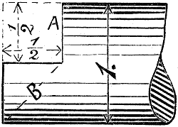
Fig. 2882.
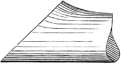
Fig. 2883.
Let the length of the two pieces be longer than the finished length to an amount equal to the diameter. Then cut out a piece as at a, in Fig. 2882, the step measuring half the diameter of the bar as shown. The shoulder a is then thrown back with the hammer, and the piece denoted by the dotted line b is cut off, leaving the shaft as shown in Fig. 2883.
The faces of the scarf should be somewhat rounding, so that when the weld is put together contact will take place in the centre of the lapping areas. Then, as the surfaces come together, the air and any foreign substances will be forced out, whereas, were the surfaces hollow the air and any cinder or other foreign substances would be closed in the weld, impairing its soundness.
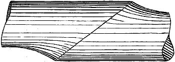
Fig. 2884.
The lap of the two pieces, when scarfed in this manner, is shown in Fig. 2884.
To take the welding heat the fire should be cleaned out and clear coked coal, and not gaseous coal, used. The main points in a welding heat are, to heat the iron equally all through, to obtain the proper degree of heat, and to keep the scarfed surfaces as free from oxidation, and at the same time as clean, as possible.
To accomplish these ends the iron must not be heated too quickly after it is at a good red heat, and the fire must be so made that the blast cannot meet it at any point until it has passed through the bed of the fire.
When the iron is getting near the welding heat it may be sprinkled with white sand, which will melt over it and form a flux that will prevent oxidation and cool the exterior, giving time to the interior to become equally heated. The sand should be thrown on the work while in the fire, as removing the work from the fire causes it to oxidize or scale rapidly. The work should be turned over and over in the fire, the scarf face being kept uppermost until the very last part of the heating, when the blast must be put on full, the bed of the fire kept full and clear so that there shall be sufficient bed to prevent the blast from meeting the heat until it has passed through the glowing coals.
When the heat is taken from the fire it should meet the anvil with a blow, the scarfed face being downwards, to jar off any dirt, cinder, &c., and the scarf should be cleaned by a stroke or two of a wire brush. But as every instant the iron is in the air it is both cooling and oxidizing, these operations must be performed as quickly as possible.
The two scarfs being laid together as shown in Fig. 2884, the first blows must be delivered lightly, so as not to cause the upper piece to move, and as quickly as possible, the force of the blows being increased regularly and gradually until the weld is sufficiently firm to hold well together, when it may be turned on edge and the edges of the scarf hammered to close and weld the seam. If this turning is done too soon, however, it may cause the two halves to separate. When the weld is firmly and completely made the enlarged diameter due to the scarfing may be forged down, working the iron as thoroughly as possible.
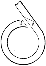
Fig. 2885.
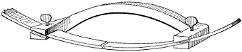
Fig. 2886.
To form the scarf of a ring or collar, one end is bevelled, as at b in Fig. 2885 and after the piece is bent to a circle it is cut off and bevelled as at a. When a slight band is to be welded, and it is difficult to steady the ends to bring them together, a clamp may be used to hold them as in Fig. 2886.
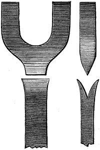
Fig. 2887.
Fig. 2887 represents a tongue weld, and it is obvious that to insure soundness the wedge piece should fit in the bottom of the split, which may be well closed upon it by the hammer blows.
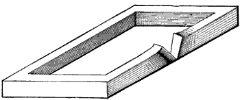
Fig. 2888.
Fig. 2888 represents an example of a V-weld applied to welding up a band that is to be square when finished, and as the lengths of the sides must be equal when finished, the side on which the weld is made should be made shorter, so that in stretching under the welding blows it will be brought to its proper length. The V form of weld is employed because it stretches less in welding than the lap weld. The V-piece to be welded in should bear at the bottom of the V, and the weld made by fullering.
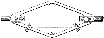
Fig. 2889.
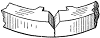
Fig. 2890.
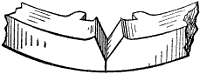
Fig. 2891.
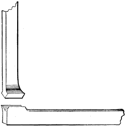
Fig. 2892.
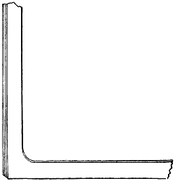
Fig. 2893.
Welds of this kind are obviously most suitable for cases in which the weld is required to influence the shape of the piece as little as possible. The figures above, which are taken from Mechanics, illustrate as an example the repairing of a broken strap for the beam of a river steamboat. The crack is at a, Fig. 2889, and is held together by a clamp as shown; a V-recess is cut out as in Fig. 2890, and this recess is fullered larger, as in Fig. 2891. A V-block is then welded in. The strap is then turned over a second V-groove, cut out and fullered out, and a second V-piece welded in. By thus welding one side at a time the welding is taken in detail as it were, and the blows can be less heavy than if a larger weld were made at one heat, as would be the case if but one V block were used. A similar form of weld may be employed to form a square corner, as is shown in Fig. 2892, which is taken from “The Blacksmith and Wheelwright.” In this example the inside corner is shown to have a fillet, which greatly increases the difficulty of the job. The weld is made by first fullering the V-piece on the sides and on the rounded corner and then laying the piece on the anvil to forge down, the fullering leaving the finished job as in Fig. 2893.

Fig. 2894.
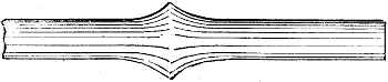
Fig. 2895.
When one piece has to be driven on to the other, the weld is called a pump-weld, for which the ends should be rounded as in Fig. 2894, so that they will meet at their centres, and will, when struck endways to make the weld, come to the shape shown in Fig. 2895.
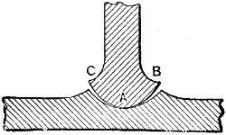
Fig. 2896.
It is obvious that in this case the interior of the iron comes together and is welded, and that dirt, &c., is effectually excluded; hence if the iron is properly heated the weld may be as sound as a lap weld, and is preferred by many as the sounder weld of the two. When a stem requires to be welded to a large flat surface, the pump weld is the only one possible, being formed as in Fig. 2896, in which the stem is supposed to be welded to a frame. The plate is cupped as shown, and the metal being driven up on the sides as much as possible, the stem overlaps well at c b, so that it may be fullered there. The stem should first meet its seat at a, so that dirt, &c., may squeeze out as the welding proceeds.
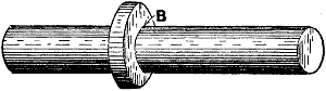
Fig. 2897.
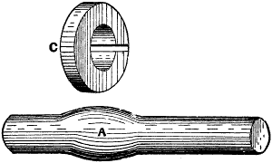
Fig. 2898.
Figs. 2897 and 2898 represent an example of welding a collar on round iron. The bar is upset so as to enlarge it at a, where the collar is to be. The collar is left open at the joint, and while it is cold it is placed on the red-hot bar and swaged until the ends are closed. The welding of the whole may then be done at one heat, swaging the outside of the collar first. Unless the bar is upset there would be a crack in the neck b of the collar on both sides.
Welding Angle Iron.—Let it be required to form a piece of straight angle iron to a right angle.

Fig. 2899.
The first operation is to cut out the frog, leaving the piece as shown in Fig. 2899; the width at the mouth a of the frog being 3⁄4 inch to every inch of breadth measured inside the flange as at b.
The edges of the frog are then scarfed and the piece bent to an acute angle; but in this operation it is necessary to keep the scarfs quite clean and not to bend them into position to weld until they are ready for the welding heat; otherwise scale will form where the scarfs overlap and the weld will not be sound.
The heat should be confined as closely as possible to the parts to be welded; otherwise the iron will scale and become reduced below its proper thickness.
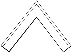
Fig. 2900.
The iron is then bent to the shape shown in Fig. 2900; and the angle to which it is bent is an important consideration. The object is to leave the overlapping scarf thicker than the rest of the metal, and then the stretching which accompanies the welding will bring the two arms or wings to a right angle.
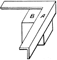
Fig. 2901.
It is obvious, then, that the thickness of the metal at the weld determines the angle to which the arms must be bent before welding. The thicker the iron the more acute the angle. If the angle be made too acute for the thickness of the iron at the weld there is no alternative but to swage the flange down and thin it enough to bring the arms to a right angle. Hence it is advisable to leave the scarf too thick rather than too thin, because while it is easy to cut away the extra metal, if necessary, it is not so easy to weld a piece in to give more metal. In very thin angle irons, in which the wastage in the heating is greater in proportion to the whole body of metal, the width of the frog at a in Fig. 2901 may be less, as, say, 9⁄16 inch for every inch of angle-iron width measured as at b in the figure. For angles other than a right angle the process is the same, allowance being made in the scarf-joint and bend before welding for the stretching that will accompany the welding operation.
The welding blows should be light and quick, while during the scarfing the scale should be cleaned off as soon as the heat leaves the fire, so that it will not drive into the metal and prevent proper welding. The outside corner should not receive any blows at its apex; and as it will stretch on the outside and compress on the inside, the forging to bring the corner up square should be done after the welding.
The welding is done on the corner of an angle block, as in Fig. 2901, in which a is the angle iron and b the angle block.
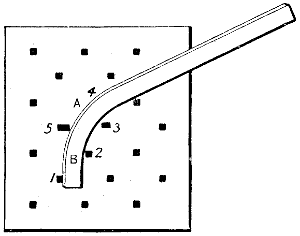
Fig. 2902.
To bend an angle iron into a circle, with the flange at the extreme diameter, the block and pins shown in Fig. 2902 are employed. The block is provided with the numerous holes shown for the reception of the pins. The pins marked 1 and 2 are first inserted and the iron bent by placing it between them and placed under strain in the necessary direction. Pins 3 and 4 are then added and the iron again bent, and so on; but when the holes do not fall in the right position, the length of the pin-heads vary in length to suit various curves.
To straighten the iron it is flattened on the surface a and swaged on the edge of the flange b, the bending and straightening being performed alternately.
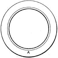
Fig. 2903.
When the flange of the angle iron is to be inside the circle, as in Fig. 2903, a special iron made thicker on the flange a is employed. The bending is accomplished, partly by the pins as before, and partly by forging thinner, and thus stretching the flange a while reducing it to its proper thickness.
To Forge a Bolt by Hand.—The blanks for bolts must be cut off sufficiently long to admit of one end being upset to form the head, the amount of this allowance, obviously, being determined by the size of the head.
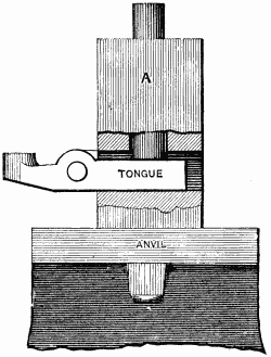
Fig. 2904.
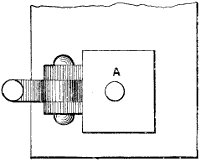
Fig. 2905.
Fig. 2904 is a side view, partly in section, and Fig. 2905 a top view of an anvil block for upsetting the ends of blanks to form the heads of bolts. The stem fits into the square hole of the anvil. The tongue is pivoted as shown in the top view to two lugs provided on the block; upon the tongue rests a steel pin whose length determines the height to which the blank will project above the top of the block, and, therefore, the amount or length of blank that will be upset to form the head, this amount being three times the diameter of the bolt for black heads.
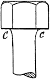
Fig. 2906.
The hole for the blank is made about 1⁄64 inch larger in diameter than the designated size of the bolt, to permit of the easy extraction of the blank after it is upset, this extraction being accomplished by striking the end of the tongue with the hammer. If the block is made of cast iron the upper end of the hole will become worn after forging five hundred or six hundred bolts, leaving the bolts with a rounded neck, as at c c in Fig. 2906; a steel block, however, will forge several thousand bolts without becoming enlarged.
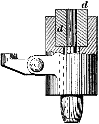
Fig. 2907.
An excellent plan is to provide the block with removable dies, such as at d d in Fig. 2907, which are easily renewed, a number of such dies having different diameters of bore fitted to the same block.
When the bolt end is sufficiently reset or enlarged to form the head it is laid in a bottom swage, containing three of the six sides of the hexagon, and a hammer blow on the uppermost part of the end forges a flat side. After each blow the work is revolved one-sixth of a revolution, and as the angles of the swage are true they obviously true the angles of the bolt head. After the head has been roughed down it is necessary to flatten it again under the head and on the end, for which purpose it may be placed in the heading block shown in Fig. 2904, after which the sides of the head may be finished and the cupping tool for chamfering the head applied.
The bolt may require passing from the heading tool to the swage several times, as forging it in one direction spreads it in another.
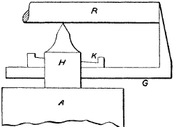
Fig. 2908.
In shops where bolt-making is of frequent occurrence a special bolt-making device is usually employed. It consists of an oliver or foot hammer, having two hammers and an anvil; in the square hole at one end of the anvil fits a hardy or bottom chisel, such as shown in Fig. 2908, for cutting up the bar or rod iron into bolt blanks; a is the anvil, h the hardy, and g a gauge to determine the length cut off the rod r to form a blank. An upsetting or heading device corresponding to that in Fig. 2907 is provided, and at the other end of the anvil is the swage for forming the bolt head.
The object of having two hammers is that one may be used for the upsetting of the blank and the other for the swage. The swaging hammer is provided with a hole and set-screw to receive top swages, and bolt hammers are adjustable for height so that they may be set so that their faces will meet the work fair.
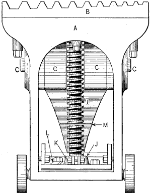
Fig. 2909.
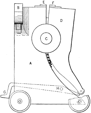
Fig. 2910.
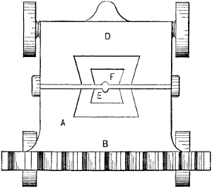
Fig. 2911.
Figs. 2909 to 2911 represent front, side, and top views of Pratt & Whitney’s portable bolt-forging device. It is provided with an elevating screw that permits the employment of a single bolster-pin for all lengths of bolt for a given diameter, instead of requiring a separate pin for each different length of bolt. In the figures, a is a frame carried upon wheels, and to which is pivoted at c c the jaw d. The bolt-gripping dies are shown at e f. A treadle g is pivoted at h, and acts upon the lower end of d, causing the die f to grip or release the bolts, as may be required. The bolster-pin rests upon the end of the screw i, which enters at its foot a split nut j, which is caused to grip and lock the screw by operating the nut of the bolt k that passes through the split of the nut. l is a spring that lifts the treadle when it is relieved of the pressure of the operator’s foot.
At m is a leather washer to protect the nut j from the scale that falls from the forging. The operation is as follows:—
The nut k is released and the screw i operated to suit the length of bolt required. Then j is caused to clamp the screw by operating the nut k. The blank for the bolt is placed in the dies resting on the bolster-pin, which in turn rests upon the end of the screw i. The treadle g is depressed, and the bolt blank clamped between e and f. The helper then with the sledge upsets the blank end to form the bolt head, and the blacksmith forges it to shape in the former bar b, which is provided with impressions for the form of head required, these impressions being of varying sizes, as shown. The device is so strongly proportioned as to be very solid, and is found to be a most useful addition to the blacksmith’s shop.
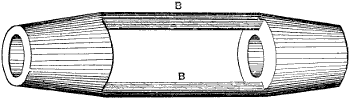
Fig. 2912.
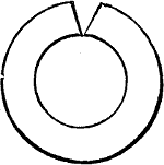
Fig. 2913.
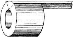
Fig. 2914.
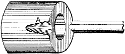
Fig. 2915.
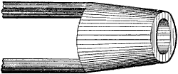
Fig. 2916.
To forge a turn buckle, such as in Fig. 2912, we bend two rings, such as in Fig. 2913, and weld into the open ends a piece as shown in Fig. 2914, on the opposite side a recess a, Fig. 2915, is cut out to receive a second piece, which being welded in the work appears as in Fig. 2916, and the end may be drawn taper. Two such pieces welded together obviously complete the job.
VOL. II. EXAMPLES IN HAND FORGING. PLATE XVI.
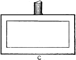
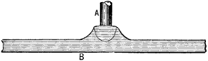
Fig. 2917. Fig. 2918.
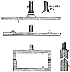
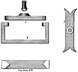
Fig. 2920.
Fig. 2919.
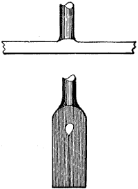
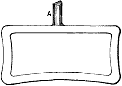
Fig. 2921. Fig. 2922.
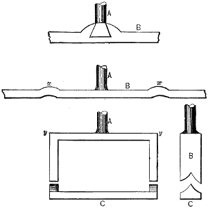
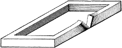
Fig. 2924.

Fig. 2925.

Fig. 2923. Fig. 2926.
Fig. 2917 represents a yoke for the slide valve of a steam engine or a locomotive, which may be forged by either of the following methods:
Fig. 2918 represents a stem a welded into the bar b, which may be bent to the required rectangle and welded at the ends.
A second method is to jump the stem d and split it open as in the side view in Fig. 2919. The bar e is forged with a projecting piece to go in the split of d, and after the weld is made, bar e is drawn to size as shown, leaving the two projections x where the corners are to come, which is necessary in order to have sufficient stock to bring the corners up square. The ends of e are split open as in the end view at f, and a piece g is then welded to f.
In a third method the end of the stem is rounded for the weld, as shown in Fig. 2920. The ends of the bar j are then split open and piece k welded on.
It is to be observed with reference to the two last methods that in hammering to forge the weld the frame is closed, so that after welding the swaging to finish may be carried on until the frame is brought to square, and any superfluous metal may be cut away; whereas if the kind of weld is such as to stretch the sides, it may happen that to get a sound weld will stretch the side welded too long and throw the frame out of shape.
Suppose, for example, that a scarf weld were made on the side of the yoke opposite to the stem, and if, in welding, the scarf is hammered too much, it would draw it out too much and throw the whole frame out of shape, as in Fig. 2921, so that the welded side would require to be jumped to bring it back to the proper length again.
A fourth method is to take a piece of iron and punch a hole in it, and then split it open up to the hole, as in Fig. 2922, and by opening out the split form the stem and part of the frame out of the solid, forging the remainder of the frame by the plan described for either the second or third methods.
A fifth method is to make the weld of the stem as in Fig. 2923, then forge out the bar b, leaving projections x x to bring the corners y y up square, and after bending to shape and squaring up to weld in a piece c.
A sixth method is to form the band first as in Fig. 2924, form the stem as in Fig. 2925, and weld as in Fig. 2926.
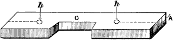
Fig. 2927.
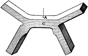
Fig. 2928.
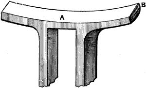
Fig. 2929.
Figs. 2927, 2928, and 2929 represent a method of forging a fifth wheel for a vehicle. A rectangular piece of Norway iron is fullered to form the recess at c in Fig. 2927. Holes are then punched at h and splits are made to the dotted lines shown in the figure. The ends are then opened out, forming a piece such as in Fig. 2928. The letter a represents the same face of the work in all the figures, being the edge in Fig. 2927, and the top face after the ends are opened out. The four arms may then be dressed to shape, the two lower ones being drawn out and threaded before being finally closed to shape. A piece may then be welded on one end, as at b, to complete the circle.
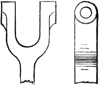
Fig. 2930.
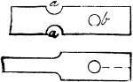
Fig. 2931.
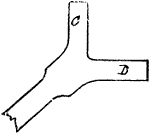
Fig. 2932.
To forge a double eye, such as in Fig. 2930, we may take a piece of sufficient size and fuller at a a, Fig. 2931; a hole is then punched at b, and it is then split through to the dotted line in Fig. 2931, and opened out as in Fig. 2932, and then forged to shape.
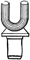
Fig. 2933.
Bending.—Fig. 2933 represents a tool for bending pieces of small diameter to a short curve, either when cold or heated. In bending hot iron it is advantageous to confine the heat as closely as possible to the part to be bent, as a more true bend may then be obtained.
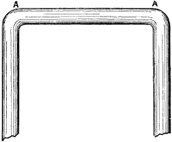
Fig. 2934.
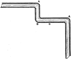
Fig. 2935.
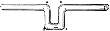
Fig. 2936.
As an example in bending, let it be required to bend a straight shaft into a crank shaft, and the following method (from “The Blacksmith and Wheelwright”) is pursued. The shaft is first bent as in Fig. 2934. The piece is next bent as in Fig. 2935, and finally as in Fig. 2936, the corners a a and b b corresponding in all the figures.
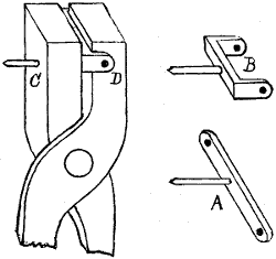
Fig. 2937.
Blacksmith’s Bending Blocks.—In cases where a great number of pieces of the same size and shape are required to be bent during the forging process, a great deal of time may be saved and greater accuracy secured in the work by the employment of bending devices. Thus, in Fig. 2937 is shown at a a clip requiring to be bent to the shape at b. A pair of tongs is provided with a hole at c to receive the stem of the clip, and the jaw d is made of the necessary width to close the ends of the forging upon. It is obvious that the hole c being in the middle of the width of the tong jaw, the wings will be equidistant from the pin.
Figs. from 2938 to 2943 represent bending devices.
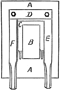
Fig. 2938.
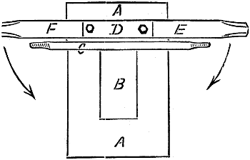
Fig. 2939.
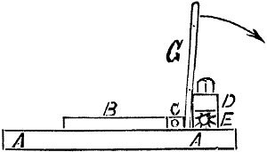
Fig. 2940.
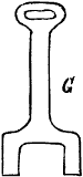
Fig. 2941.
Figs. 2938, 2939, and 2940, represent a “former” for a stake pocket for freight cars. a is a cast-iron plate having a projection b, around which the stake pocket c is bent. d is fast upon a, and affords a pivoted joint for the bending levers e f. The work is placed in the former as shown in Fig. 2939, and levers e f are swung around to the position shown in Fig. 2938. To enable the work to be put in and taken out rapidly and yet keep it firmly against the end of b, a hand-piece g is used as in Fig. 2940, its form being more clearly shown in the enlarged Fig. 2941. Sufficient room is allowed between b and d to admit the work, and the end of the piece g, which is pressed in the direction denoted by the arrow in Fig. 2940, forcing the work against b. A number of the pieces are piled on the fire so as to heat them sufficiently fast to keep the former at work, and the bottom piece is the one taken out.
The corners of the work are by this process brought up square and the faces are kept out of wind. The surface a forms a level bed. These advantages will be readily appreciated by all smiths who have had comparatively thin work to bend to a right angle in the ordinary way.
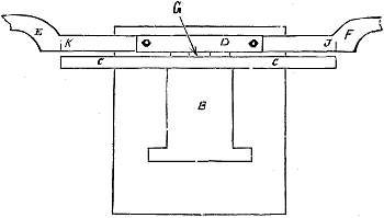
Fig. 2942.
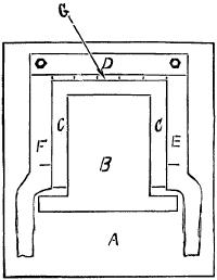
Fig. 2943.
Figs. 2942 and 2943 represent a similar former for the step irons of freight cars. In Fig. 2942 the piece is thrown in place ready to be bent, its ends being fair with the lines j k on the bending levers e f. In Fig. 2943 the levers are shown closed and the work c therefore bent to shape. The bed plates a are mounted on a suitable frame to raise them to a convenient height for the blacksmith.
Forging a Stable-fork.—In the manufactories where stable and hay forks are made, the whole process of forging is done under the trip hammer, and is conducted as follows:—
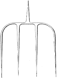
Fig. 2944.
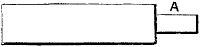
Fig. 2945.
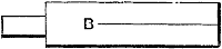
Fig. 2946.
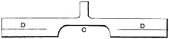
Fig. 2947.
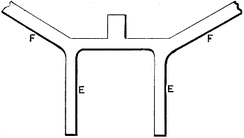
Fig. 2948.
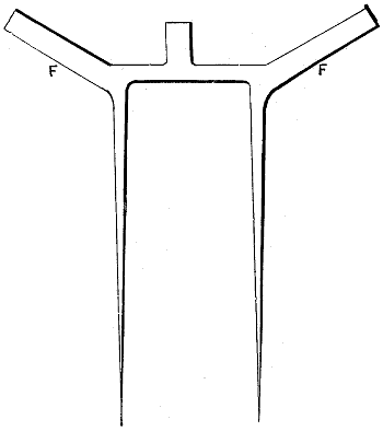
Fig. 2949.
To forge a four-tined fork, such as in Fig. 2944, a blank piece of steel is employed, its dimensions being 53⁄4 inches long, 73⁄4 inches wide, and 1⁄2 inch thick. The first operation is to swage down one end, as at a in Fig. 2945. A split is then cut down as at b in Fig. 2946. The split is then opened out as in Fig. 2947, and is fullered and drawn out at c. Two more splits are then made at d d, and the ends are bent open as in Fig. 2948, when the four tines e e and f f are drawn out and shaped out. The stem, a, Fig. 2945, is then finished for the handle.
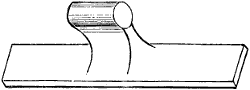
Fig. 2950.
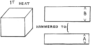
Fig. 2951.
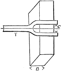
Fig. 2952.
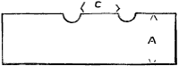
Fig. 2953.
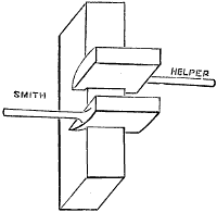
Fig. 2954.
The following example of forging under the hammer is derived from The Engineer, of London, England. Fig. 2950 shows the piece to be forged. A block of iron, Fig. 2951, is drawn out as in the figure, the dimensions of a and b being considerably above the finished ones. A forked tool t, Fig. 2952, may be used to nick the two grooves shown in Fig. 2953, which marks the locations for the hub and forms a starting guide for the two fullering tools shown in Fig. 2954, one of which is held by the blacksmith and the other by the helper. After this fullering the forging will appear as in Fig. 2955. The ends e, f may then be drawn out, having the shape as in Fig. 2956. To shape the curve between the side of the hub and the body of the stem, grooves are formed as in Figs. 2957 and 2958, y and b being top and bottom half-round fullers, and these two grooves are subsequently made into one by means of larger half-round fullers, as in Fig. 2959. The object of making two small fullered grooves and then making them into one is to prevent the fullering from spreading the body of the stem by lessening the strain due to using a large fuller at once. The piece now appears as in Fig. 2960.
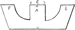
Fig. 2955.
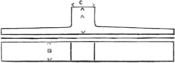
Fig. 2956.
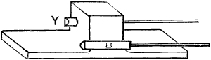
Fig. 2957.
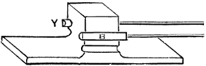
Fig. 2958.
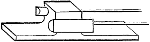
Fig. 2959.
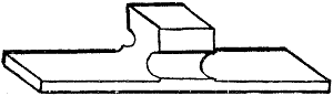
Fig. 2960.
The next operation is to cut or punch away the metal between the ends of the hub and the body of the piece, which is accomplished as follows:
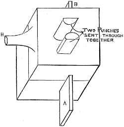
Fig. 2961.
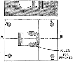
Fig. 2962.
A top and bottom die and block are made to contain the work, as in Fig. 2961, a and b being the work ends. Through these dies are two holes for two punches which are driven through together as marked; the dies are held fair, one with the other, by four holes in the lower and four pins in the upper one, a section and top view of the dies being shown in Fig. 2962.
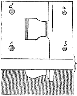
Fig. 2963.
The piece is at this stage roughed out to shape all over, and may be finished between the pair of finishing dies shown in Fig. 2963, which also represents a plan and sectional view, a, b, c, d being the holes to receive guide pins in the upper die.
An excellent example of forgings in Siemens Martin steel is given in the following figures, being the rope sockets for the Brooklyn Bridge.
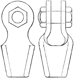
Fig. 2964.
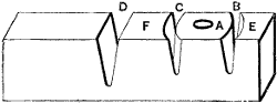
Fig. 2965.
Fig. 2964 represents two views of the forgings, and it will be readily perceived that they are very difficult to make on account of the taper hole, which is shown in dotted lines. The first operation was to take a bar of steel 61⁄2 inches square and punch a hole, as at a Fig. 2965.
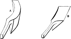
Fig. 2966.
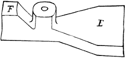
Fig. 2967.
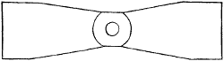
Fig. 2968.
Next the piece was fullered at b, c by the fuller a, Fig. 2966, and cut partly off as at d. The fullering at b was then extended by a spreading fuller, shaped as at b, and the end e was drawn out. Then the piece was cut off at d. Next the spreading fuller was applied to c, and the forging appeared as in Fig. 2967. The end f was then drawn out, and the appearance was as in Fig. 2968.
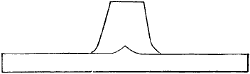
Fig. 2969.
The next operation was to enlarge the hole a, Fig. 2965, by drawing taper mandrels through it, the mandrels being about 7 in. long, having 1⁄2-in. tapes on them, and being successively larger. With the last of these mandrels in the hole the hub was drawn out to length and diameter, leaving the forging roughly shaped, but having the form shown in Fig. 2969.
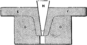
Fig. 2970.
To finish the hole the forging was then placed in a block such as shown at g, in Fig. 2970, a finishing punch being shown at h in the figure.
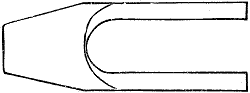
Fig. 2971.
The next operation was to let the steam hammer down upon the face of the punch and bring up the wings e f parallel, but not more than parallel, as then the mandrel could not be got out; the forging then appearing as in Fig. 2971.
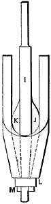
Fig. 2972.
The next process was to put in a bar mandrel such as shown in Fig. 2972 at i, the pieces j, k fitting on their sides to the mandrel and being curved outside to the circular and taper shape of the hole. The wings e f may then be closed on the mandrel to their proper width and the whole hub end being trimmed by hand, all the previous work having been done under the steam hammer. The hub being finished the key m may be taken out and the washer l taken off, when i can be pulled out, leaving j k to be taken out separately. A pair of tongs are then put through the finished hub end, while the wings are punched and trimmed under the steam hammer, and subsequently finished by hand.
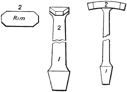
Fig. 2973.
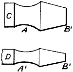
Fig. 2974.
The forging of wrought-iron wheels for locomotives is an excellent example. The spokes are first forged in two pieces, as 1 and 2 in Fig. 2973, and then welded to form the complete spoke. Piece 1 is first forged in dies under the steam hammer to the form shown in Fig. 2974, the dimensions being correct when the faces of the dies meet. The stud c d is then drawn out to the required length and dimensions.
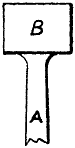
Fig. 2975.
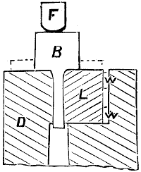
Fig. 2976.
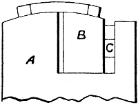
Fig. 2977.
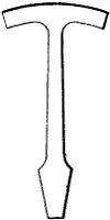
Fig. 2978.
The upper half of the spoke is first blocked out under dies to the shape shown in Fig. 2975, and the block b spread so as to form a section of the wheel rim, as shown in Fig. 2976, in which d is a die, l a movable piece wedged up by the wedges w w, and removable to enable the extraction of the forging, and f is an end view of the fuller, the use of which is necessary to cause the metal to spread sufficiently in the direction of the dotted lines. The corners of the rim are then cut off, as shown in Fig. 2973, and the rim is bent in a block having its top face of the necessary curve, as in Fig. 2977, a being the block, and b a piece movable, to allow the extraction of the work, and fastened in place by the key or keys c. The two pieces are then welded together, their lengths, &c., being gauged by a sheet-iron template, formed as in Fig. 2978. The welding is usually performed with sledge-hammers, but as soon as the pieces will hold well together, the drawing down is done under a steam hammer.
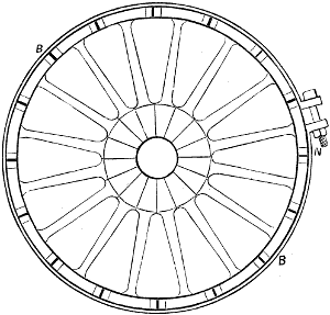
Fig. 2979.
The spokes thus forged are then put together, as in Fig. 2979, b representing a wrought-iron band, encircling the rim of the wheel and closed upon the same by the bolt and nut at n.
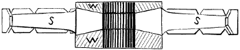
Fig. 2980.
Two washers are then forged, to be placed and welded in as at w w, in Fig. 2980.
The welding together of the spokes and of the washers to the spokes proceeds simultaneously. The washers are heated to come to a welding heat at the same time as the wheel hub is at a welding heat, and the two are welded together under a steam hammer. During the heating of the wheel hub, however, the band b, Fig. 2979, is tightened up with the screw to bring the spokes into closer contact when heated to the welding point.
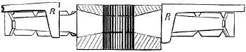
Fig. 2981.
The seams between the spokes at the circumference of the hub are welded with bars as shown in Fig. 2981, in which r r are two bars of iron which are operated by hand as rams. The wedge shape of the washers on their inside faces performs important duty in spreading the metal as well as simply compressing it, giving a much more sound weld than a flat washer or plain dish would.
The rim of the wheel is welded up as follows:
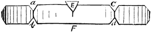
Fig. 2982.
In Fig. 2982 are shown four spokes of the rim as they appear after the hub is welded. Into the V spaces, as a, b, c, d; wedges of metal, of the form shown at e, are welded, after which the surplus metal of e is cut away, and the rim is solid as at f. In this process, however, it is necessary to weld all the pieces on one side of the wheel, as at a b, &c., except one, which must be left unwelded until all the pieces save one on the other side are welded, and the wheel must be allowed to become quite cool before these last two pieces are welded. Otherwise the strain induced by the contraction of the wheel rim while cooling will often cause the rim to break with a report as loud as that of a rifle. In those cases in which this breakage does not occur the wheel will be very apt to break at some part of the rim, when subjected to heavy shocks or jars.
The Figs. 2983 to 2999 (which are taken from Mechanics), illustrate the method employed to forge the rudder frame of the steamship Pilgrim.
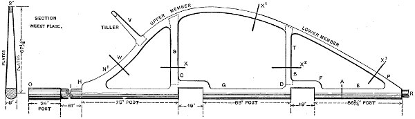
Fig. 2983.
A side elevation of the rudder frame is shown in Fig. 2983.
The forging is made in eight separate pieces, which are so united as to make three pieces. These three pieces are finally joined by five welds. The whole length being 29 feet 113⁄4 inches, and the weight 6,500 pounds.
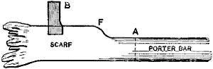
Fig. 2984.
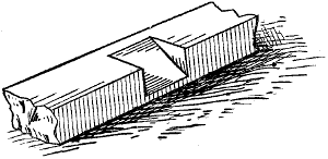
Fig. 2985.
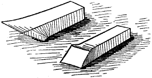
Fig. 2986.
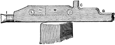
Fig. 2987.
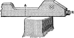
Fig. 2988.

Fig. 2989.
The work is commenced by piling and welding on the porter-bar at the point in the shaft marked a. The stubs b and c having been previously prepared, the pile on the porter-bar is heated and welded up and drawn, shown in Fig. 2984, and scarfed as shown in Fig. 2985; the piece, shown in Fig. 2986, is then laid in the scarf and welded; then the part from b to a is finished to size, the finished forging of the post being shown in Fig. 2984. The surplus stock to the right of b, Fig. 2984, is worked down into the post e, and the distance from b to f is thus made correct without loss of stock or time. The curve at d, Fig. 2983, was worked down somewhere near, and then another pile and weld carries the job to g. Here the same operations as at first are repeated, and the arm c is welded in. There is left a good lump of stock in front of c, and by another pile and weld enough is added to make the job to i, as shown in Fig. 2987. Holes are then punched at j and l, and the piece of stock m cut entirely out. A cut is made to l with a hack opening out the piece n from the shaft. A taper punch, with a 3-inch point and a 4-inch head, is then driven at l; to throw the piece n out into the position shown at n1, Fig. 2983; n1 is then finished, and the post from l to j brought to forging size; then, by the ordinary process of piling, welding and drawing, the shaft is finished from i to o. Next the porter-bar is cut off, so as to leave stock enough to make the lower part of the shaft, as shown in Fig. 2988. A hole was punched at q, and the stubs drawn out, as shown in Fig. 2989, which gives the post complete.

Fig. 2990.
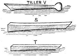
Fig. 2991.
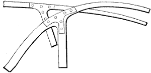
Fig. 2992.
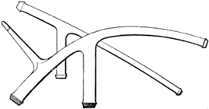
Fig. 2993.
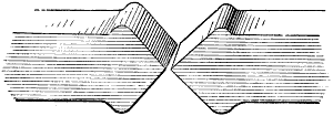
Fig. 2994.
The pieces s and t, and the tiller v, having been forged, as shown in Fig. 2991, the upper member of the frame is started on the porter-bar at w, Fig. 2983, and filed, welded and drawn to make the job as far as x1. Wooden templates, such as in Fig. 2992, are provided for the pieces of the frame, the first extending from w to x1 and x, and the second including the part from x1 to x2 and x3. After w, x1 has been drawn out with lumps left where the tiller and the arm s are to be joined, the scarf is made for the tiller and that is welded in, and the job finished to piece s. The scarf for s is then made, and s welded in. This makes the upper member of the frame. The lower member is made in the same way, starting at x3. These two members are shown complete in Fig. 2993. The post, Fig. 2989, was sent to the machine shop, and was turned, planed, bored, and slotted, as shown in Fig. 2990. The frame was now ready to be pieced up, by welds at w, x, x1, x2, and x3, Fig. 2983.
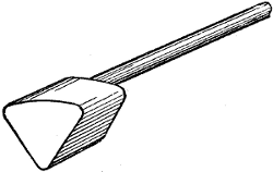
Fig. 2995.
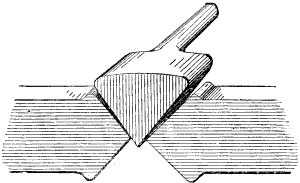
Fig. 2996.
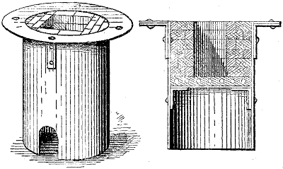
Fig. 2997.
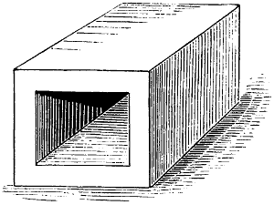
Fig. 2998.
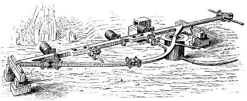
Fig. 2999.
The several sections are now ready to be welded together for the complete frame, these welds being made as follows: The ends are upset as in Fig. 2994 to receive on each side a V-piece such as in Fig. 2995, which is heated on a porter-bar, and is of a more acute wedge than the ends to be welded, so that when laid in as in Fig. 2996 it will touch at the bottom first, and thus allow the air and whatever dirt there may be on the surfaces to squeeze out as the welding proceeds. The method of heating the frame for these welds is as follows: The V-block (which has the grain of the iron running in the same direction as that of the frame) being heated in the blacksmith’s forge, the frame is clamped together and counterbalanced by means of weights, so that it may be laid over a fire pot, constructed as in Fig. 2997. This fire pot is lined with brick, and has its blast supplied through a piece of flexible tube. The anvil is of cast iron, shaped as in Fig. 2998, and placed on the other side of the frame and opposite to the fire pot or portable forge, as shown in Fig. 2997, so that the frame, when the heat is ready, may be turned over upon the blocks on which it rests, and the part to be welded will come upon the anvil. After one side is welded the anvil and the portable forge change places, and the second side of the weld is made.
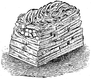
Fig. 3000.

Fig. 3001.
In the following figures (which are taken from Mechanics) is illustrated the method employed to build up the shaft shown in Fig. 3001, which was for the steamer Pilgrim. Forgings of such large dimensions are built up of pieces or slabs, called blooms, which are themselves forged from scrap iron, which is piled as in Fig. 3000. For the forging in question this scrap iron consisted of old horseshoes, boiler-plate clippings, boiler rivets and old bolts, and the first step in the manufacture is to form this scrap into piles ready for the furnace.
Fig. 3002.
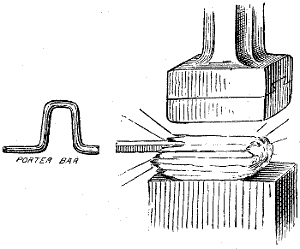
Fig. 3003.
These piles are made upon pieces of pine board 1⁄2 inch thick by 16 inches long by 10 inches wide. On these the scrap is piled about 14 inches high, each pile weighing about 270 pounds. After piling, the scrap goes into the furnace and is raised to a welding heat, the board retaining its form as a glowing coal almost to the last. The pile of scrap is heated so nearly to melting as to stick together enough so that it can be picked up in a long pair of tongs with peculiarly-shaped jaws, and, as these tongs are suspended by a chain from an overhead traveller running on an iron track, the bloom is easily transferred to the anvil of the steam hammer, where, after one or two blows, a small porter-bar with a crank end, such as shown in Fig. 3003, is welded on, and the pile is rapidly drawn out into a square bar. When completed the porter-bar is cut off, and the bar is laid aside to cool. The pile of scrap has now become a “bloom,” such as shown in Fig. 3002, and has been reduced in weight from 270 lbs. to 240 lbs. The bloom is about 30 inches by 5 inches by 5 inches in dimensions, and has rounded, ragged ends, and a surface full of lines marking welding of the individual pieces, and at the ends looking as though the scrap had united by melting rather than by any welding process.