Volume 1 — Chapter XIV.—MEASURING MACHINES, TOOLS, AND DEVICES. (continued 2)
Reading edition
“The question of tapered bolts involves at once this difficulty: that we have to drill a straight hole, then the tapered reamer must take out all the metal that must be removed in order to convert a straight into a tapered hole. The straight hole is maintained in its size by taking out the least amount of metal. It follows that the tapered reamer would be nearest right which would also take out the least amount of metal.
“Then you come to the question of the shape of the taper. When I was engaged building locomotives in Cincinnati, a great many years ago, we used bolts the taper of which was greater than I shall recommend to you. In regard to the compression that would take place in bolts, no piece of iron can go into another piece of iron without being smaller than the hole into which it is intended to go. If it is in any degree larger, it must compress the piece itself or stretch the material that is round it. So, if you adopt a tapered bolt, you cannot adopt a certain distance that it shall stand out before you begin to drive it, for there will be more material to compress in a large piece than in a small one. Metal is elastic. Within the elastic limit of the metal you may assume the compression to be a spring. In a large bolt you have a long spring, and in a short one you have a short spring. If you drive a half-inch bolt into a large piece of iron, it is the small bolt which you compress; therefore the larger the bolt the more pressure you can give to produce the same result. Hence, if you adopt the taper bolt, you will have to use your own discretion, unless you go into elaborate experiments to show how far the bolt head should be away from the metal when you begin to drive it.
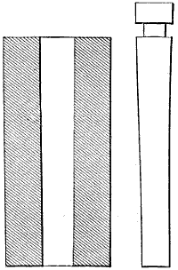
Fig. 1399.
“Certain builders of locomotives put their stub ends together with tapered bolts, but do not use tapered bolts in any other part of the structure. The Baldwin Works use tapered bolts wherever they are body bound bolts. They make a universal taper of 1⁄16 inch to the foot. An inch bolt 12 inches long would be 11⁄16 inches diameter under the head. They make all their bolts under 9 inches long 1⁄16 larger under the head than the name of the bolt implies. Thus a 3⁄4 inch bolt would be 13⁄16 inch under the head, provided it was 9 inches long or under. Anything over 9 inches long is made 1⁄8 inch larger under the head, and still made a taper of 1⁄16 inch to the foot. A locomotive builder informs me that a taper of 1⁄8 inch to the foot is sometimes called for, and the Pennsylvania road calls for 3⁄32 inch to the foot. But the majority of specifications call for 1⁄16 inch to the foot. The advantage of 1⁄16 inch taper lies in the fact that a bolt headed in the ordinary manner can be made to fill the requirements, provided it is made of iron. You may decide that bolts should be tapered, for the reason that when a tapered bolt is driven into its place it can be readily knocked loose, or if that bolt, when in its place, proves to be too loose, you have merely to drive it in a little farther: these are arguments in favor of tapered bolts, showing their advantage. It is easier to repair work that has tapered bolts than work that has straight bolts. If you adopt a tapered bolt, say, with a taper of 1⁄16 inch to the foot, you are going to effect the making of those bolts and the boring of those holes in a commercially accurate manner, so that they can be brought into the interchangeable system. To carry this out, you require some standard to start with, and the simplest system that one can conceive is this: Let us imagine that we have a steel plug and grind it perfectly true. We have the means of determining whether that is a taper of 1⁄16 inch, thanks to the gentlemen who are now making these admirable gauges. We have a lathe that can turn that taper. I think if you go into the manufacture of these bolts, you will be obliged to use a lathe which will always turn a uniform taper. Having made a female gauge, Fig. 1399, 8 inches long and 11⁄16 inches diameter with a taper of 1⁄16 inch to the foot, this is the standard of what? The area of the bolt, not of the hole it goes into. We now make a plug, Fig. 1399. Taking that tapered plug we should be able to drop it into the hole. Your taper reamer is made to fit this, but you require to know how deep the hole should be. Remember, I said this is the gauge that the bolts are made by. Now let us suppose that we have this as a standard, and to that standard these reamers are made. We decide by practice how much compression we can put upon the metal. For inch bolts, and, say, all above 1⁄2 inch, we might, say, allow the head to stand up 1⁄8 of an inch. Let us make another female gauge like Fig. 1399, but turned down 1⁄8 of an inch shorter. We then shall have the hole smaller than it was before. It is this degree smaller, .0065 of an inch; that is a decimal representing how much smaller that hole is when you have gone down 1⁄8 of an inch on a taper of 1⁄16 inch to the foot.
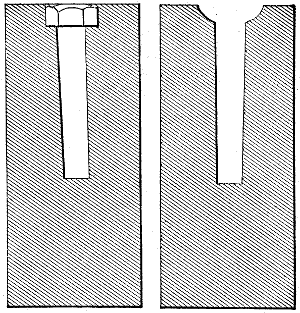
Fig. 1400.
“Having got this tapered plug, you then must have the means of making the bolts commercially accurate in the shop. For that purpose you must have some cast-iron plugs. Those are reamed with a reamer that has no guard on it, but is pushed into it until the plug—this standard plug—is flush with the end of it. If you go in a little too far it is no matter. Having produced that gauge, we gauge first the one that is used on the lathe for the workman to work by, and he will fit his bolt in until the head will be pushed up against it. If you have a bolt to make from a straight piece of iron, I should advise its being done in two lathes. Here are those beautiful gauges of the Pratt and Whitney Company, which will answer the present purpose; one of these gauges measuring what the outside of the bolt will be, the other gauge 1⁄16 of an inch larger will mark the part under the head. Messrs. Baldwin have a very good system of gauges. All the cast-iron plugs which they use for this purpose are square. Holes are cut in the blocks the exact size of the bolts to be turned up, as shown in Fig. 1400. The object of this is that there shall be no mistake as to what the gauge is. These gauges can be readily maintained, because they have to go back into the room to the inspector. He puts this plug in. If it goes in and fits flush, it is all right. If the plug goes in too far, it is worn. He then turns a little off the end and adjusts it.
“Now practically through machine shops we find that we have to use cast-iron gauges. We take, for instance, 2-inch shafting. Shafting can only be commercially accurate. Therefore we make cast-iron rings and if those rings will go on the shafting it is near enough accurate for merchantable purposes. But this ring will wear in a certain time. Therefore it must not be used more than a certain number of days or hours. Here you have a system that is simple in the extreme. You have all this in two gauges, one gauge being made as a mere check on that tapered plug which is the origin of all things, the origin being 1⁄8 or 7⁄16, or 1⁄4 of an inch shorter if the bolt is very large. There is where you have to use your own judgment. But having adopted something practical you then can use your reamer which is necessary to produce a hole of a given size. If this reamer wears, you then turn off this wrought-iron collar far enough back to let it go in that much farther. I know of no other way by which you can accomplish this result so well as by that in use at the Baldwin Locomotive Works. I think that the system originated with Mr. Baldwin himself.
“I do not feel disposed to recommend to you any particular taper to be adopted, because it is not a question like that of screw-threads. In screw-threads we throw away the dies that are used upon bolts, which are perishable articles. The taper that has once been adopted in locomotive establishments is a perpetual thing. If the Pennsylvania railroad and all its branches have adopted 3⁄32, it is folly to ask them to change it to 1⁄16 of an inch, because their own connections are large enough to make them independent of almost any other corporation, and the need of absolute uniformity in their work would cause them to stick to that particular thing. Any of you having five, six, seven, or two or three hundred engines, must make up your minds what you will do. When we adopt a standard for screw-threads, a screw-thread is adopted which has a manifest advantage. A bolt that has one screw thread can be used on any machine. But once having adopted a taper on a road, it is very difficult to make a change; and whether it is wisdom for this Association to say that thus-and-so shall be the standard taper, is a question I am unable to answer. Therefore I am unwilling to present any taper to you, and only present the facts, but will say that 1⁄16 inch is enough. The less taper you have the less material you have to cut away. But to say that 1⁄16 inch is preferable to 1⁄32 inch is folly, because no human being could tell the difference. If a bolt has 5° taper on the side, it may set in place; if it has 7°, it may jump out. That is the angle of friction for iron or other metals. Five degrees would be an absurd angle for a taper bolt. Anything, then, that will hold; that is, if you drive the bolt it will set there.
“This presentation may enable you to arrive at some conclusion. Nothing is more desirable than an interchangeable system. In making turning lathes we try to make all parts interchangeable, and we so fit the sliding spindle. Every sliding spindle in the dead head of the lathe has to be fitted into its own place. We know of no method of making all holes of exactly the same size that shall be commercially profitable. The only way we could surmount that difficulty was to put two conical sleeves in that should compress. We have so solved the problem. We now make spindles that are interchangeable, and we do not fit one part to the other. But that is not the case with bolts. You cannot put the compressing thimbles on them, therefore, you have to consider the question, How can you make holes near enough, and how can you turn the bolts near enough alike?”
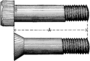
Fig. 1401.
Fig. 1401 represents, and the following table gives the taper adopted by the Baldwin Locomotive Works.
Bolt threads, American standard, except stay bolts and boiler studs, V-threads, 12 per inch; valves, cocks and plugs, V-threads, 14 per inch, and 1⁄8 inch taper per 1 inch.
Standard bolt taper 1⁄16 inch per foot.
Length of bolts from head to end of thread equals a.
Diameter of bolt under the head as follows:—
3⁄64 inch larger at b for 9 inch and under
1⁄16 „ „ over 9 inch to 12 inch
3⁄32 „ „ „ 12 „ to 18 „
1⁄8 „ „ „ 18 „ to 24 „
5⁄32 „ „ „ 24 „ to 30 „
3⁄16 „ „ „ 30 „ to 36 „
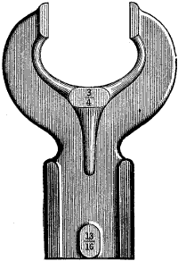
Fig. 1402.
It is obvious that a plug or collar gauge simply determines what is the largest dimension of the work, and that although it will demonstrate that a piece of work is not true or round yet it will not measure the amount of the error. The work may be oval or elliptical, or of any other form, and yet fit the gauge so far as the fit can be determined by the sense of feeling. Or suppose there is a flat place upon the work, then except in so far as the bearing marks made upon the work by moving it within the gauge may indicate, there is no means of knowing whether the work is true or not. Furthermore, in the case of lathe work held between the lathe centres it is necessary to remove the work from the lathe before the collar gauge can be applied, and to obviate these difficulties we have the caliper gauge shown in Fig. 1402. The caliper end is here shown to be for 3⁄4 inch, and the plug end for 13⁄16 inch. If the two ends were for the same diameter one gauge only would be used for measuring external and internal work of the same diameter, but in this case the male cannot be tested with the female gauge; whereas if the two ends are for different diameters the end of one gauge may be tested with that of another, and their correctness tested, but the workman will require two gauges to measure an external and internal piece of the same diameter.
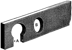
Fig. 1403.
For small lathe work of odd size as when it is required to turn work to fit holes reamed by a worn reamer that is below the standard size, a gauge such as in Fig. 1403, is sometimes used, the mouth a serving as a caliper and the hole b as a collar gauge for the same diameter of work. It is obvious that such a gauge may be applied to the work while it is running in the lathe, and that when the size at a wears too large the jaw may be closed to correct it; a plan that is also pursued to rectify the caliper gauge shown in Fig. 1402.
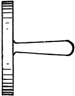
Fig. 1404.

Fig. 1405.
On large work, as, say, of six inches in diameter, a gauge, such as in Fig. 1404, is used, being short so that it may be light enough to be conveniently handled; or sometimes a piece such as in Fig. 1405 is used as a gauge, the ends being fitted to the curvature of the bore to be tested. Gauges of these two kinds, however, are generally used more in the sense of being templates rather than measuring tools, since they determine whether a bore is of the required size rather than determine what that size is.
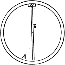
Fig. 1406.
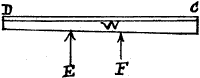
Fig. 1407.
For gauging work of very large diameter, as, say, several feet, to minute fractions of an inch, as is necessary, for example, for a shrinkage fit on a locomotive tire, the following method is employed. In Fig. 1406 let a represent a ring, say, 5 feet bore, and requiring its bore to be gauged to within, say, 1⁄100 inch. Then r represents a rod made, say, 1⁄2 inch shorter than the required diameter of bore, and w, Fig. 1407, represents a wedge whose upper surface c d is curved, its lower surface being a true plane. The thickness at the end c is made, say, 51⁄100 inch, while that at d is 48⁄100 inch; or in other words, there is 3⁄100 of an inch taper in the length of the wedge. Suppose then that the rod r is placed in the bore of a as in figure, and that the wedge just has contact with the work bore and with the end of the rod when it has entered as far as e in Fig. 1407, and that point e is one-third of the length of the wedge, then the bore of a will measure the length of the rod r plus 49⁄100 of an inch. But if the wedge passed in to line f, the latter being two-thirds the length of the wedge from d, then the bore would be 50⁄100 larger than the length of the rod r. It is obvious that with this method the work may be measured very minutely, and the amount of error, if there be any, may be measured.
The rod must be applied to the work in the same position in which its measurement was made, otherwise its deflection may vitiate the measurement. Thus, if the rod measures 4 feet 111⁄2 inches when standing vertical, it must be applied to the work standing vertical; but if it was measured lying horizontal, it must be applied to the work lying horizontal, as there will be a difference in its length when measured in the two positions, which occurs on account of variations in its deflection from its own weight.
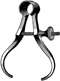
Fig. 1408.
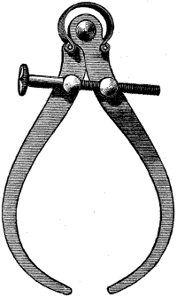
Fig. 1409.
For simply measuring a piece of work to fit it to another irrespective of its exact size as expressed in inches and parts of an inch the common calipers are used. Fig. 1408 represents a pair of spring calipers, the bow acting as a spring to keep the two legs apart, and the screw and nut being used to close them against the spring pressure. The slightness of the legs enables these calipers to be forced or to spring over the work, and thus indicate by the amount of pressure it requires to pass them over the work how much it is above size, and therefore how much it requires to be reduced. But, on the other hand, this slightness renders it somewhat difficult to measure with great correctness. A better form of outside calipers is shown in Fig. 1409, in which in addition to the stiffness of the pivoted joint a bow spring acts to close the caliper legs, which are operated, to open or close them, by operating the hand screw shown, the nuts in which the screw operates being pivoted to the caliper legs. The advantage of this form is that the calipers may be set very readily, while there is no danger of the set or adjustment of the calipers altering from any slight blow or jar received in laying them down upon the bench.
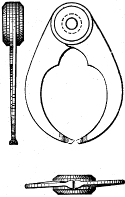
Fig. 1410.
Fig. 1410 gives views of a common pair of outside calipers such as the workman usually makes for himself. When this form is made with a sufficiently large joint, and with the legs broad and stiff as in the figure, they will serve for very fine and accurate adjustments.

Fig. 1411.
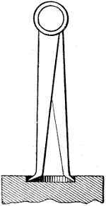
Fig. 1412.
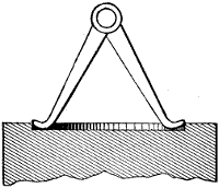
Fig. 1413.
Fig. 1411 represents a pair of inside calipers for measuring the diameters of holes or bores. The points of these calipers should be at an angle as shown in the Fig. 1412, which will enable the points to enter a long distance in a small hole, as is denoted by the dotted lines in the figure. This will also enable the extreme points to reach the end of a recess, as in Fig. 1413, which the rounded end calipers, such as in this figure, will not do.
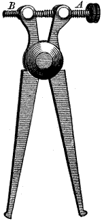
Fig. 1414.
Fig. 1414 represents a pair of inside calipers with an adjustment screw having a right-hand screw at a and a left-hand one at b, threaded into two nuts pivoted into the arms, so that by operating the screw the legs are opened or closed, and are locked in position, so that they cannot move from an accidental blow. But as the threads are apt to wear loose, it is preferable to provide a set screw to one of the nuts so as to take up the wear and produce sufficient friction to prevent looseness of the legs.
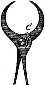
Fig. 1415.
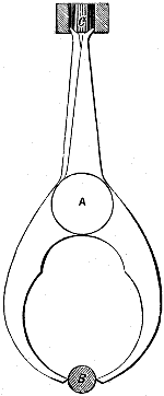
Fig. 1416.
Calipers are sometimes made double, that is to say, the inside and the outside calipers are provided in the one tool, as in Fig. 1415, which represents a pair of combined inside and outside calipers having a set screw at c to secure the legs together after the adjustment is made. The object of this form is to have the measuring points equidistant from the centre of the pivot a in Fig. 1416, so that when the outside legs are set to the diameter of the work as at b, the inside ones will be set to measure a hole or bore of the same diameter as at c.
This, however, is not a desirable form for several reasons, among which are the following:—
In the first place outside calipers are much more used than inside ones, hence the wear on the points are greatest. Again, the pivot is apt to wear, destroying the equality of length of the points from the centre of the pivot; and in the third place the shape of the points of calipers as usually made vitiates the correctness of the measurements.
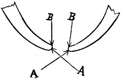
Fig. 1417.
Fig. 1417, for example, represents the ordinary form, the points being rounded; hence, when the legs are closed the point of contact between the inside and outside calipers will be at a, while when they are opened out to their fullest the points of contact will be at b. This may, however, be remedied to a great extent by bevelling off the ends from the outside as shown in Fig. 1416.
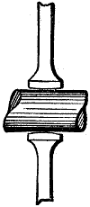
Fig. 1418.
The end faces of outside calipers should be curved in their widths, as in Fig. 1418, so that contact shall occur at the middle, and it will then be known just where to apply the points of the inside calipers when testing them with the outside ones.
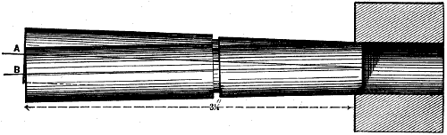
Fig. 1419.
Inside and outside calipers are capable of adjustment for very fine measurements; indeed, from some tests made by the Pratt and Whitney Company among their workmen it was found that the average good workman could take a measurement with them to within the twenty-five thousandth part of an inch. But the workman of the general machine shop who has no experience in measuring by thousandths has no idea of the accuracy with which he sets two calipers in his ordinary practice. The great difference that the one-thousandth of an inch makes in the fit of two pieces may be shown as in Fig. 1419, which represents a collar gauge of 5⁄8 inch in diameter, and a plug 1⁄1000 inch less in diameter, and it was found that with the plug inserted 1⁄8 inch in the collar it could be moved from a to b, a distance of about 5⁄16 inch, which an ordinary workman would at once recognise as a very loose fit.
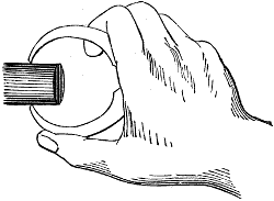
Fig. 1420.
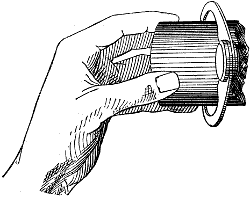
Fig. 1421.
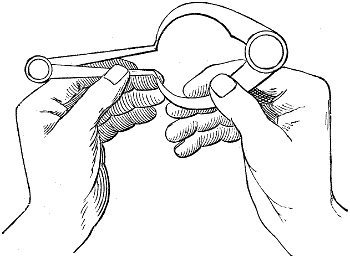
Fig. 1422.
If the joints of outside calipers are well made the calipers may upon small work be closed upon the work as in Fig. 1420, and the adjustment may be made without requiring to tap or lightly knock the caliper legs against the work as is usually done to set them. But to test the adjustment very finely the work should be held up to the light, as in Fig. 1421, the lower leg of the calipers rested against the little finger so as to steady it and prevent it from moving while the top leg is moved over the work, and at the same time moving it sideways to find when it is held directly across the work. For testing the inside and outside calipers together they should for small diameters be held as in Fig. 1422, the middle finger serving to steady one inside and one outside leg, while one leg only of either calipers is grasped in the fingers.
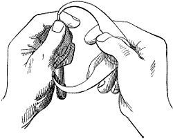
Fig. 1423.
For larger dimensions, as six or eight inches, it is better, however, to hold the calipers as in Fig. 1423, the forefinger of the left hand serving to rest one leg of each pair on the contact being thus tested between the legs that are nearest to the operator.
The adjustment of caliper legs should be such that contact between the caliper points and the work is scarcely, if at all, perceptible. If with the closest of observation contact is plainly perceptible, the outside calipers will be set smaller than the work, while in the case of inside calipers, they would be set larger; and for this reason it follows that if a bore is to be measured to have a plug fitted to it, the inside calipers should have barely perceptible contact with the work bore, and the outside calipers should have the same degree of contact, or, if anything, a very minute degree of increased contact. On the other hand, if a bore is to be fitted to a cylindrical rod the outside calipers should be set to have the slightest possible contact with the rod, and the inside ones set to have as nearly as possible the same degree of contact with the outside ones, or, if anything, slightly less contact. For if in any case the calipers have forcible contact with the work the caliper legs will spring open and will therefore be improperly set.
Calipers should be set both to the gauge and to the work in the same relative position. Let it be required, for example, to set a pair of inside calipers to a bore, and a pair of outside calipers to the inside ones, and to then apply the latter to the work. If the legs of the inside calipers stand vertical to the bore for setting they should stand vertical while the outside calipers are set to them, and if the outside calipers are held horizontally while set to the inside ones they should be applied horizontally to the work, so as to eliminate any error due to the caliper legs deflecting from their own weight.
To adjust calipers so finely that a piece of work may be turned by caliper measurement to just fit a hole; a working or a driving fit without trying the pieces together, is a refinement of measurement requiring considerable experience and skill, because, as will be readily understood from the remarks made when referring to gauge measurements, there are certain minute allowances to be made in the set of the calipers to obtain the desired degree of fit.
In using inside calipers upon flat surfaces it will be found that they can be adjusted finer by trusting to the ear than the eye. Suppose, for example, we are measuring between the jaws of a pillow-block. We hold one point of the calipers stationary, as before, and adjust the other point, so that, by moving it very rapidly, we can just detect a scraping sound, giving evidence of contact between the calipers and the work. If, then, we move the calipers slowly, we shall be unable, with the closest scrutiny, to detect any contact between the two.
Calipers possess one great advantage over more rigid and solid gauges, in that the calipers may be forced over the work when the degree of force necessary to pass them on indicates how much the work is too large, and therefore how much it requires reducing. Thus, suppose a cylindrical piece of work requires to be turned to fit a hole, and the inside calipers are set to the bore of the latter, then the outside calipers may be set to the inside ones and applied to the work, and when the work is reduced to within, say, 1⁄100 inch the calipers will spring open if pressed firmly to the work, and disclose to the workman that the work is reduced to nearly the required size. So accustomed do workmen become in estimating from this pressure of contact how nearly the work is reduced to the required diameter, that they are enabled to estimate, by forcing the calipers over the work, the depth of the cut required to be taken off the work, with great exactitude, whereas with solid gauges, or even caliper gauges of solid proportions, this cannot be done, because they will not spring open.
The amount to which a pair of calipers will spring open without altering their set depends upon the shape: thus, with a given joint they will do so to a greater extent in proportion as the legs are slight, whereas with a given strength of leg they will do so more as the diameter of the joint is large and the fit of the joint is a tight one. But if the joint is so weak as to move too easily, or the legs are so weak as to spring too easily, the calipers will be apt in one case to shift when applied to the work, and in the other to spring so easily that it will be difficult to tell by contact when the points just touch the work and yet are not sprung by the degree of contact. For these reasons the points of calipers should be made larger in diameter than they are usually made: thus, for a pair of calipers of the shape shown in Fig. 1410, the joint should be about 11⁄4 inches diameter to every 6 inches of length of leg. The joint should be sufficiently tight that the legs can just be moved when the two legs are taken in one hand and compressed under heavy hand pressure.
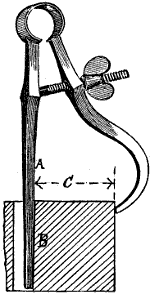
Fig. 1424.
For measuring the distance of a slot or keyway from a surface, the form of calipers shown in Fig. 1424 is employed; the straight leg has its surface a true plane, and is held flat against the surface b of the slot or keyway, and the outside or curved leg is set to meet the distance of the work surface measuring the distance c. These are termed keyway calipers.
There are in general machine work four kinds of fit, as follow: The working or sliding fit; the driving fit; the hydraulic press fit; and the shrinkage fit. In the first of these a proper fit is obtained when the surfaces are in full contact, and the enveloped piece will move without undue friction or lost motion when the surfaces are oiled. In the second, third, and fourth, the enveloped piece is made larger than the enveloping piece, so that when the two pieces are put together they will be firmly locked.
It is obvious that in a working or sliding fit the enveloped piece must be smaller than that enveloping it, or one piece could not pass within the other. But the amount of difference, although too small to be of practical importance in pieces of an inch or two in diameter and but few inches in length, is appreciable in large work, as, say, of two or more feet in diameter. A journal, for example, of 1⁄10 inch diameter, running in a bearing having a bore of 1⁄1000 inch larger diameter, and being two diameters in length, would be instantly recognised as a bad fit; but a journal 6 inches in diameter and two diameters or 12 inches long would be a fair fit in a bearing having a bore of 61⁄1000 inches. In the one case the play would be equal to one one-hundredth of the shaft’s diameter, while in the other case the play would equal but one six-thousandth part of the shaft’s diameter. In small work the limit of wear is so small, and the length of the pieces so short, that the 1⁄1000 of an inch assumes an importance that does not exist in larger work. Thus, in watch work, an error of 1⁄1000 inch in diameter may render the piece useless; in sewing machine work it may be the limit to which the tools are allowed to wear; while in a steamship or locomotive engine it may be of no practical importance whatever.
A journal 1⁄10 inch in diameter would require to run, under ordinary conditions, several years to become 1⁄1000 inch loose in its bearing. Some of this looseness, and probably nearly one half of it, will occur from wear of the bearing bore; hence, if a new shaft of the original standard diameter be supplied the looseness will be reduced by one-half. But a 6-inch journal and bearing would probably wear nearly 1⁄1000 inch loose in wearing down to a bearing which may take but a week or two, and for these reasons among others, standard gauges and measuring tools are less applicable to large than to small work.
The great majority of fits made under the standard gauge system consist of cylindrical pieces fitting into holes or bores. Suppose then that we have a plug and a collar gauge each of an inch diameter, and a reamer to fit the collar gauge, and we commence to ream holes and to turn plugs to fit the collar gauge, then as our work proceeds we shall find that as the reamer wears, the holes it makes will get smaller, and that as the collar gauge wears, its bore gets larger, and it is obvious that the work will not go together. The wear of the gauge obviously proceeds slowly, but the wear of the reamer begins from the very first hole that it reams, although it may perform considerable duty before its wear sensibly affects the size of the hole. Theoretically, however, its size decreases from the moment it commences to perform cutting duty until it has worn out, and the point at which the wearing-out process may have proceeded to its greatest permissible limit is determined by its reduction of size rather than by the loss of its sharpness or cutting capacity. Obviously then either the reamer must be so made that its size may be constantly adjusted to take up the wear, as in the adjustable reamer, or else if solid reamers are used there must be a certain limit fixed upon as the utmost permissible amount of wear, and the reamer must be made above the standard size to an amount equal to the amount of this limit, so that when the reamer has worn down it will still bore a hole large enough to admit the plug gauge. To maintain the standard there should be in this case two sets of gauges, one representing the correct standard and the other the size to which the reamer is to be made when new or restored to its proper size.
The limit allowed for reamer wear varies in practice from 1⁄1000 to 1⁄10000 of an inch, according to the requirements of the work. As regards the wear of the standard gauges used by the workmen they are obviously subject to appreciable wear, and must be returned at intervals to the tool room to be corrected from gauges used for no other purpose.
To test if a hole is within the determined limit of size a limit gauge may be used. Suppose, for example, that the limit is 1⁄1000 of an inch, then a plug gauge may be made that is 1⁄1000 of an inch taper, and if the large end of this plug will enter the hole, the latter is too large, while if the small end will not enter, the hole is too small.
When only a single set of plug and collar gauges are at hand the plug or the collar gauge may be kept to maintain the standard, the other being used to work to, both for inside and outside work. Suppose, for example, that a plug and collar gauge are used for a certain piece of work and that both are new, then the reamer may be made from either of them, because their sizes agree, but after they have become worn either one or the other must be accepted as the standard of size to make the reamer to. If it be the collar gauge, then the plug gauge is virtually discarded as a standard, except in that if the plug gauge be not used at all it may be kept as a standard of the size to which the collar gauge must be restored when it has worn sufficiently to render restoration to size necessary. If this system be adopted the size of the reamer will be constantly varying to suit the wear of the collar gauge, and the difficulty is encountered that the standard lathe arbors or mandrels will not fit the holes produced, and it follows that if standard mandrels are to be used the reamers must when worn be restored to a standard size irrespective of the wear of the gauges, and that the standard mandrels must be made to have as much taper in their lengths as the limit of wear that is allowed to the reamers. Suppose, for example, that it is determined to permit the reamer to wear the 1⁄2000 of an inch before restoring it to size, then in an inch mandrel the smallest end may be made an inch in diameter and the largest 11⁄2000 inch in diameter, so that however much the reamer may be worn within the limit allowed for wear the hole it produces will fit at some part in the length of the standard mandrel. But as the reamer wears smaller its size must be made as much above its designated standard size as the limit allowed for wear; hence, when new or when restored to size, the reamer would measure 11⁄2000 inches, and the hole it produced would fit the large end of the mandrel. But as the reamer wore, the hole would be reamed smaller and would not pass so far along the mandrel, until finally the limit of reamer wear being reached the work would fit the small end of the mandrel. The small end of the mandrel is thus the standard of its size, and the wear of the collar gauge is in the same direction as that of the reamer. Thus, so long as the collar gauge has not worn more than the 1⁄2000 of an inch it will, if placed upon the mandrel, fit it at some part of its length.
Now suppose that the plug gauge be accepted as the standard to which the reamer is to be made, and that to allow for reamer wear the reamer is made, say, 1⁄2000 inch larger than the plug gauge, the work being made to the collar gauge. Then with a new reamer and new or unworn gauges the hole will be reamed above the standard size to the 1⁄2000 inch allowed for reamer wear. As the reamer wears, the hole it produces will become smaller, and as the collar gauge wears, the work turned to it will be larger, and the effect will be that, to whatever extent the collar gauge wears, it will reduce the permissible amount of reamer wear, so that when the collar gauge had worn the 1⁄2000 inch the work would not go together unless the reamer was entirely new or unworn.
In a driving fit one piece is driven within the other by means of hammer blows, and it follows that one piece must be of larger diameter than the other, the amount of the difference depending largely upon the diameter and length of the work.
It is obvious, however, that the difference may be so great that with sufficiently forcible blows the enveloping piece may be burst open. When a number of pieces are to be made a driving fit, the two pieces may be made to fit correctly by trial and correction, and from these pieces gauges may be made so that subsequent pieces may be made correct by these gauges, thus avoiding the necessity to try them together.
In fitting the first two pieces by fit and trial, or rather by trial and correction, the workman is guided as to the correctness of the fit by the sound of the hammer blows, the rebound of the hammer, and the distance the piece moves at each blow. Thus the less the movement the more solid the blow sounds, and the greater the rebound of the hammer the tighter the fit, and from these elements the experienced workman is enabled to know how tightly the pieces may be driven together without danger of bursting the outer one.
What the actual difference in diameter between two pieces may require to be to make a driving fit is governed, as already said, to a great extent by the dimensions of the pieces, and also by the nature of the material and the amount of area in contact. Suppose, for example, that the plug is 6 inches long, and the amount of pressure required to force it within the collar will increase with the distance to which it is enveloped by the collar. Or suppose one plug to be 3 inches and another to be 6 inches in circumference, and each to have entered its collar to the depth of an inch, while the two inside or enveloped pieces are larger than the outside pieces by the same amount, the outside pieces being of equal strength in proportion to their plugs, so that all other elements are equal, and then it is self-evident that the largest plug will require twice as much power as the small one will to force it in another inch into the collar, because the area of contact is twice as great. It is usual, therefore, under definite conditions to find by experiment what allowance to make to obtain a driving or a forcing fit. Thus, Mr. Coleman Sellers, at a meeting of the Car Builders Association, referring to the proper amount of difference to be allowed between the diameters of car axles and wheel bores in order to obtain a proper forcing or hydraulic fit, said, “Several years ago some experiments were made to determine the difference which should be made between the size of the hole and that of the axle. The conclusion reached was that if the axle of standard size was turned 0.007 inch larger than the wheel was bored it would require a pressure of about 30 tons to press the axle into the wheel.” The wheel seat on the axle here referred to was 47⁄8 inches in diameter and 7 inches long. It is to be remarked, however, that the wheel bore being of cast iron and the axle of wrought iron the friction between the surfaces was not the same as it would be were the two composed of the same metal. This brings us to a consideration of what difference in the forcing fit there will be in the case of different metals, the allowance for forcing being the same and the work being of the same dimensions.
Suppose, for example, that a wrought-iron plug of an inch in diameter is so fitted to a bore that when inserted therein to a distance of, say, 2 inches, it requires a pressure of 3 lbs. to cause it to enter farther, then how much pressure would it take if the bore was of cast iron, of yellow brass, or of steel, instead of wrought iron. This brings us to another consideration, inasmuch as the elasticity and the strength of the enveloping piece has great influence in determining how much to allow for a driving, forcing, or a shrinkage fit.
Obviously the allowance can be more if the enveloping piece be of wrought iron, copper, or brass, than for cast iron or steel, because of the greater elasticity of the former. Leaving the elasticity out of the question, it would appear a natural assumption that the pieces, being of the same dimensions, the amount of force necessary to force one piece within the other would increase in proportion as the equivalents of friction of the different metals increased.
This has an important bearing in practice, because the fit of pieces not made to standard gauge diameter is governed to a great extent by the pressure or power required to move the pieces. Thus, let a steel crosshead pin be required to be as tight a fit into the crosshead as is compatible with its extraction by hand, and its diameter in proportion to that of the bore into which it fits will not be the same if that bore be of wrought iron, as it would be were the bore of steel, because the coefficient of friction for cast steel on cast iron is not the same as that for steel on wrought iron. In other words, the lower the coefficient of friction on the two surfaces the less the power required to force one into the other, the gauge diameters being equal. In this connection it may be remarked that the amount of area in contact is of primary importance, because in ordinary practice the surfaces of work left as finished by the steel cutting tools are not sufficiently true and smooth to give a bearing over the full area of the surfaces.
This occurs for the following reasons. First, work to be bored must be held (by bolts, plates, chuck-jaws, or similar appliances) with sufficient force to withstand the pressure of the cut taken by the cutting tool, and this pressure exerts more or less influence to spring or deflect the work from its normal shape, so that a hole bored true while clamped will not be so true when released from the pressure of the holding clamps.
To obviate this as far as possible, expert workmen screw up the holding devices as tight as may be necessary for the heavy roughing cuts, and then slack them off before taking the finishing cuts.
Secondly, under ordinary conditions of workshop practice, the steel cutting tools do not leave a surface that is a true plane in the direction of the length of the work, but leave a spiral projection of more or less prominence and of greater or less height, according to the width of that part of the cutting edge which lies parallel to the line of motion of the tool feed, taken in proportion to the rate of feed per revolution of the work.
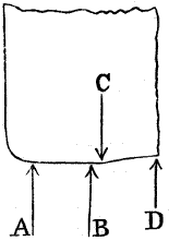
Fig. 1424a.
Let the distance, Fig. 1424a, a to b lie in the plane of motion of the tool feed, and measure, say, 1⁄4 inch, the tool moving, say, 5⁄16 inch along the cut per lathe revolution. Suppose the edge from b to d to lie at a minute angle to the line of tool traverse, and the depth of the cut to be such that the part from b to c performs a slight cutting or scraping duty, then the part from b to c will leave a slight ridge on the work plainly discernible to the naked eye in what are termed the tool marks.
The obvious means of correcting this is to have the part a b of greater width than the tool will feed along the cut, during one revolution of the work (or the cutter, as the case may be); but there are practicable obstacles to this, especially when applied to wrought iron, steel, or brass, because the broader the cutting edge of a tool the more liable it is to spring, as well as to jar or chatter, leaving a surface showing minute depressions lying parallel to the line of tool feed.
If the cutting tool be made parallel and cylindrical on its edges, and clearance be given on the front end of its diameter only, so as to cut along a certain distance only of its cylindrical edge, the rest being a close fit to the bore of the work, the part having no cutting edge, that is, the part without clearance, will be apt to cause friction by rubbing the bore of the work as the tool edge wears, and the friction will cause heat, which will increase as the cut proceeds, causing the hole to expand as the cut proceeds, and to be taper when cooled to an equal degree all over. This may be partly obviated by giving the tool a slow rate of cutting speed, and a quick rate of feed, which will greatly reduce the friction and consequently the heating of the tool and the work. On cast iron it is possible to have a much broader cutting edge to the tool, without inducing the chattering referred to, than is the case with wrought iron, steel, or brass, especially when the finishing cut is a very light one. If the finishing cut be too deep, the surface of the work, if of cast iron, will be pitted with numerous minute holes, which occur because the metal breaks out from the strain placed on it (and due to the cut) just before it meets the cutting edge of the tool. Especially is this the case if the tool be dull or be ground at an insufficiently acute angle.
When the work shows the tool marks very plainly, or if of cast iron shows the pitting referred to (instead of having a smooth and somewhat glossy appearance), there will be less of its surface in contact with the surface to which it fits, and the fit will soon become destroyed, because the wearing surface or the gripping surface, as the case may be, will the sooner become impaired, causing looseness of the fit. In the one case the abrasion which should be distributed over the whole area of the fitting parts is at first confined to the projections having contact, which, therefore, soon wear away. In the other case the projecting area in contact compresses, causing looseness of the fit.
Hydraulic press or forcing fits.—For securing pieces together by forcing one within the other by means of an hydraulic press, the plug piece is made a certain amount larger than the bore it is to enter, this amount being termed the allowance for forcing. What this allowance should be under any given conditions for a given metal, will depend upon the truth and smoothness of the surfaces, and on this account no universal rule obtains in general practice. From some experiments made by William Sellers & Co., it was determined that if a wheel seat (on an axle) measuring 47⁄8 inches in diameter and 7 inches long was turned 7⁄1000 of an inch larger than the wheel bore, it would require a pressure of about thirty tons to force the wheel home on the axle.
At the Susquehanna shops of the Erie railroad the measurements are determined by judgment, the operatives using ordinary calipers. If an axle 31⁄2 diameter and 6 inches long requires less than 25 tons it is rejected, and if more than 35 tons it is corrected by reducing the axle.
In order to insure a proper fit of pieces to be a driven or forced fit it is sometimes the practice to make them taper, and there is a difference of opinion among practical mechanics as to whether taper or parallel fits are the best. Upon this point it may be remarked that it is much easier to measure the parts when they are parallel than when they are taper, and it is easier to make them parallel than taper.
On the elevated railroads in New York city, the wheel bores being 41⁄8 inches in diameter and 5 inches long, the measurements are taken by ordinary calipers, the workmen judging how much to allow, and the rule is to reject wheels requiring less than about 26 tons, or more than about 35 tons, to force them on. These wheels form excellent examples, because of the excessive duty to which they are subjected by reason of the frequency of their stoppage under the pressure of the vacuum brake. The practice with these wheels is to bore them parallel, finishing with a feed of 1⁄4 inch per lathe revolution, and to turn the axle seats taper just discernible by calipers.
This may, at first sight, seem strange, but examination makes it reasonable and plain. Let a wheel having a parallel bore be forced upon a parallel axle, and then forced off again, and the bore of the wheel will be found taper to an appreciable amount, but increasing in proportion as the surface of the hole varied from a dead smoothness; in other words, varying with the depth of the tool marks in the bore and the smoothness of the cut.
Let the length of the wheel bore be 7 inches long, and the amount allowed for forcing be .004 inch, and one end of the wheel bore will have been forced (by the time it is home on the axle) over the length of 7 inches of the axle-seat, whose diameter was .004 larger than the bore: a condensation, abrasion, or smoothing of the metal must have ensued.
Now the other end of the same bore, when it takes its bearing on the shaft, is just iron, and iron without having suffered any condensation. If the tool marks be deep, those on one end will be smoothed down while those at the other remain practically intact. Clearly then, for a parallel hole, a shaft having as much taper as the wheel bore will get in being forced over the shaft best meets the requirements; or, for a parallel shaft or seat, and a taper hole (the taper being proportioned as before), the small end of the taper hole should be first entered on the shaft, and then when home both the axle and the wheel-bore will be parallel.
It may be remarked that the wheel seat on the axle will also be affected, which is quite true, but the axle is usually of the hardest metal and has the smoothest surface, hence it suffers but little; not an amount of any practical importance.
In an experiment upon this point made in the presence of the author by Mr. Howard Fry and the master mechanic of the Renovo shops of the Philadelphia and Erie railroad, an axle seat finished by a Whitney “doctor,” and parallel in diameter, was forced into a wheel having a parallel bore, and removed immediately. On again measuring the axle, the wheel-seat was found to be 1⁄1000 taper in its length.
The wheel-bore was found to be but slightly affected in its diameter, which is explained because it being very smooth, while the turning marks in the axle were plainly visible, the abrasion fell mainly upon the latter.
When the enveloping piece or bore is not solid or continuous, but is open on one side, the degree of the fit may be judged from the amount that it opens under the pressure of the plug piece.
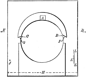
Fig. 1425.
Thus the axle brasses of American locomotives are often made circular at the back, as shown in Fig. 1425, and are forced in endways by hydraulic pressure. The degree of tightness of the brass within the box may, of course, be determined by the amount of pressure it requires to force it in, but another method is to mark a centre punch dot as at j, and before the brass is put in mark from this dot as a centre an arc of a circle as l l. When the brass is home in the box a second arc k is marked, the distance between l and k showing how much the brass has sprung the box open widening at h. In an axle box whose bore is about 4 inches to 5 inches in diameter, and 6 inches long, 1⁄32 inch is the allowance usually made.
Shrinkage fits are employed when a hole or bore requires to be very firmly and permanently fastened to a cylindrical piece as a shaft. The bore is turned of smaller diameter than its shaft, and the amount of difference is termed the allowance for shrinkage. The enveloping piece is heated so as to expand its bore; the shaft is then inserted and the cooling of the bore causes it to close or contract upon the shaft with an amount of force varying of course with the amount allowed for contraction. If this allowance is excessive, sufficient strain will be generated to burst the enveloping piece asunder, while if the allowance for shrinking is insufficient the enveloping piece may become loose.
The amount of allowance for shrinkage varies with the diameter thickness, and kind of the material; but more may be allowed for wrought iron, brass, and copper, than for cast iron or steel.
Again, the smoothness and truth of the surfaces is an important element, because the measurement of a bore will naturally be taken at the tops of the tool marks, and these will compress under the shrinkage strain, hence less allowance for contraction is required in proportion as the bore is smoother.
In ordinary workshop practice, therefore, no special rule for the amount of allowance for shrinkage obtains, the amount for a desultory piece of work generally being left to the judgment of the workman, while in cases where such work is often performed on particular pieces, the amount of allowance is governed by experience, increasing it if the pieces are found in time to become loose, and decreasing it if it is found impossible to get the parts together without making the enveloping piece too hot, or if it is found to be liable to split from the strain.
The strength of the enveloping piece is again an element to be considered in determining the amount to be allowed for shrinkage. It is obvious, for example, that a ring of 8 inches thick, and having a bore of, say, 6 inches diameter, would be less liable to crack from the strain due to an allowance of 1⁄50 inch for contraction, than would a ring of equal bore and one inch thick having the same allowance. The strength or resistance to compression of the piece enveloped in proportion to that enveloping it, is yet another consideration.
The tires for railway wheels are usually contracted on, and Herr Krupp states the allowance for contraction to be for steel tires 1⁄100 inch for every foot of diameter; in American practice, however, a greater amount is often employed. Thus upon the Erie railroad a 5 foot tire is given 1⁄16 inch contraction. The allowance for wrought iron or brass should be slightly more than it is for steel or cast iron, on account of the greater elasticity of those metals.
Examples of the practice at the Renovo shops of the Pennsylvania road are as follows:
Class E, diameter of wheel centre, 44 inches; bore of steel tire, 4315⁄16 inches.
Class D, diameter of wheel, 50 inches; bore of tire, 499⁄16 inches.
It is found that the shrinkage of the tire springs or distorts the wheel centre, hence the tires are always shrunk on before the crank-pin holes are bored.
Much of the work formerly shrunk on is now forced on by an hydraulic press. But in many cases the work cannot be taken to an hydraulic press, and shrinkage becomes the best means. Thus, a new crank pin may be required to be shrunk in while the crank is on the engine shaft, the method of procedure being as follows: In heating the crank, it is necessary to heat it as equally as possible all round the bore, and not to heat it above a very dark red. In heating it some dirt will necessarily get into the hole, and this is best cleaned out with a piece of emery paper, wrapped round a half-round file, carefully blowing out the hole after using the emery paper. Waste or rag, whether oiled or not, is not proper to clean the hole with, as the fibres may burn and lodge in the hole; indeed, nothing is so good as emery paper.
It is desirable to heat the crank as little as will serve the purpose, and it is usual to heat it enough to allow the pin to push home by hand. It is better, however, to overheat the crank than to underheat it, providing that the heat in no case exceeds a barely perceptible red heat. If, however, the crank once grips the pin before it is home, in a few seconds the pin will be held so fast that no sledge hammer will move it. It is well, therefore, to have a man stationed on each side of the crank, each with a sledge hammer, and to push the crank pin in with a slam, giving the man in front orders to strike it as quickly as possible at a given signal; but if the pin does not move home so rapidly at each blow as to make it appear certain that it will go home, the man at the rear, who should have a ten-pound sledge, should be signalled to drive out the crank pin as quickly as he possibly can for every second is of consequence. All this should be done so quickly that the pin has not had time to get heated to say 100° at the part within the crank.
So soon as the pin is home, a large piece of wetted cotton waste should be wrapped round its journal, and a stream of water kept running on it, to keep the crank pin cold. At the other end water should be poured on the pin end in a fine stream, but in neither case should the water run on the crank more than can be avoided. Of course, if the crank is off the shaft, the pin may be turned downward, and let project into water.
The reasons for cooling the pin and not the crank are as follows: If the crank be of cast iron, sudden cooling it would be liable to cause it to split or crack. If the crank pin is allowed to cool of itself, the pin will get as hot as the crank itself, and in so doing will expand, placing a strain on the crank that will to some extent stretch it. Indeed, when the pin has become equally hot with the crank it is as tight a fit as it will ever be, because after that point both pieces will cool together, and shrink or contract together, and hence the fit will be a looser or less tight one to the amount that the pin expanded in heating up to an equal temperature with the crank.
The correct process of shrinking is to keep the plug piece as cold as possible, while the outside is cooled as rapidly as can be without danger of cracking or splitting.
The ends of crank pins are often riveted after being shrunk in, in which case it is best to recess the end, which makes the riveting easier, and causes the water poured upon its face to be thrown outward, thus keeping it from running down the crank face and causing the crank to crack or split.
It sometimes becomes necessary and difficult to take out a piece that has been shrunk in, and in this event, as also in the case of a piece that has become locked before getting fully home in the shrinking process, there is no alternative but to reheat the enveloping piece while keeping the enveloped piece as cold as can be by an application of water.
The whole aim in this case is to heat the enveloping piece as quickly as possible, so that there shall be but little time for its heat to be transmitted to the piece enveloped. To accomplish this end melted metal, as cast iron, is probably the most efficient agent; indeed it has been found to answer when all other means failed.
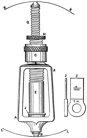
Fig. 1426.
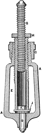
Fig. 1427.
The fine measurements necessary for shrinkage purposes render it necessary, where pieces of the same form and kind are shrunk on, to provide the workmen with standard gauges with which the work may be correctly gauged. These often consist of simple rods or pieces of iron wire of the required length. Figs. 1426 and 1427, however, represent an adjustable shrinkage gauge designed by H. S. Brown, of Hartford, Connecticut. Fig. 1427 is a sectional, and Fig. 1426 a plan side view of the gauge. a is a frame, containing at its lower end a fixed measuring piece b, and provided at its upper end with a threaded and taper split hub to receive externally the taper-threaded screw cap c, and threaded internally to receive a tube e, which is plugged at the bottom by the fixed plug f. The adjustable measuring leg g is threaded with the tube e, so as to be adjustable for various diameters of boxes, but it is locked when adjusted by the jamb-nut h. The operation is as follows: The cap-nut c and jamb-nut h are loosened and screwed back, allowing stem g and tube e to be adjusted to the exact size of the shaft for which a shrinkage fit is to be bored, as, say, in an engine crank. In setting the gauge to the diameter of the shaft, the cap end c and jamb-nut h are screwed home, so as to obtain a correct measurement while all parts are locked secure. The cap-nut c draws the split hub upon the tube e, and the jamb-nut h locks up g to e, so that the shaft measurement is taken with all lost motion, play and spring of the mechanism taken into account, so that they shall not vitiate the measurement. This being done, c is loosened so that e can be rotated, and raised up (by rotating) to admit the shrinkage gauge-piece j, whose thickness equals the amount to be allowed for the size of borer to be shrunk on the shaft. j being inserted, e is rotated back so as to bind j between the end of e and the foot piece b, when c is screwed down, clamping e again. Thus the measuring diameter of the gauge is increased to an amount due to the thickness of the gauge-piece j. At the right of Fig. 1426 an edge and side elevation of j is shown, the 12⁄1000 indicating its thickness, which is the amount allowed for shrinkage, and the 6-inch indicating that this gauge-piece is to be used for bores of 6 inches in diameter. The dotted circle k k l l represents a bore to which the gauge is shown applied.
The system of shrinking employed at the Royal Gun Factory at Woolwich, England, is thus described by Colonel Maitland, superintendent of that factory:—
“The inside diameter of the outer tube, when cold, must be rather smaller than the outside diameter of the inner tube: this difference in the diameter is called the ‘shrinkage.’ While the outer coil is cooling and contracting it compresses the inner one: the amount by which the diameter of the inner coil is decreased is termed the ‘compression.’ Again, the outer coil itself is stretched on account of the resistance of the inner one, and its diameter is increased; this increase in the diameter of an outer coil is called ‘extension.’ The shrinkage is equal to compression plus the extension, and the amount must be regulated by the known extension and compression under certain stresses and given circumstances. The compression varies inversely as the density and rigidity of the interior mass; the first layer of coils will therefore undergo more compression than the secondhand the second more than the third, and so on.
“Shrinking is employed not only as an easy and efficient mode of binding the successive coils of a built-up gun firmly together, but also for regulating as far as possible the tension of the several layers, so that each and all may contribute fairly to the strength of the gun.
“The operation of shrinking is very simple; the outer coil is expanded by heat until it is sufficiently large to fit easily over the inner coil or tube (if a large mass, such as the jacket of a Fraser gun, by means of a wood fire, for which the tube itself forms a flue; if a small mass, such as a coil, in a reverberatory furnace at a low temperature, or by means of gas). It is then raised up by a travelling crane overhead and dropped over the part on to which it is to be shrunk, which is placed vertically in a pit ready to receive it.
“The heat required in shrinking is not very great. Wrought iron, on being heated from 62° Fahr. (the ordinary temperature) to 212°, expands linearly about 1⁄1000th part of its length; that is to say, if a ring of iron 1000 inches in circumference were put into a vat of boiling water, it would increase to 1001 inches, and according to Dulong and Petit the coefficient of expansion, which is constant up to 212°, increases more and more from that point upward, so that if the iron ring were raised 150° higher still (i.e. to 362°) its circumference would be more than 1002 inches. No coil is ever shrunk on with so great a shrinkage as the 2⁄1000th part of its circumference or diameter, for it would be strained beyond its elastic limit. Allowing, therefore, a good working margin, it is only necessary to raise a coil to about 500° Fahr.,[22] though in point of fact coils are often raised to a higher degree of temperature than this in some parts, on account of the mode of heating employed. Were a coil plunged in molten lead or boiling oil (600° Fahr.) it would be uniformly and sufficiently expanded for all the practical purposes of shrinking, but as shrinkings do not take place in large numbers or at regular times, the improvised fire or ordinary furnace is the more economical mode, and answers the purpose very well.
“Heating a coil beyond the required amount is of no consequence, provided it is not raised to such a degree of temperature that scales would form; and in all cases the interior must be swept clean of ashes, &c., when it is withdrawn from the fire. With respect to the modes of cooling during the process of shrinking, care must be taken to prevent a long coil or tube cooling simultaneously at both ends, for this would cause the middle portion to be drawn out to an undue state of longitudinal tension. In some cases, therefore, water is projected on one side of a coil so as to cool it first. In the case of a long tube of different thickness, like the tube of a R. M. L. gun, water is not only used at the thick end, but a ring of gas or a heated iron cylinder is applied at the thin or muzzle end, and when the thick end cools the gas or cylinder is withdrawn from the muzzle, and the ring of water raised upward slowly to cool the remainder of the tube gradually.
“As a rule, the water is supplied whenever there is a shoulder, so that that portion may be cooled first and a close joint secured there; and water is invariably allowed to circulate through the interior of the mass to prevent its expanding and obstructing or delaying the operation; for example, when a tube is to be shrunk on a steel barrel, the latter is placed upright on its breech end, and when the tube is dropped down on it, a continual flow of cold water is kept up in the barrel by means of a pipe and syphon at the muzzle. The same effect is produced by a water jet underneath, when it is necessary to place the steel tube muzzle downward for the reception of a breech coil. As to the absolute amount of shrinkage given when building up our guns, let us take the 121⁄2-inch muzzle-loading gun of 38 tons as an example.
SHRINKAGES OF COILS OF 12.5 INCH R. M. L. GUNS.
Coils. Shrinkages. Remarks.
In Inches. In terms of diameter.
Rear. Front. Rear. Front.
Breech‑piece .02 2 .02 6 D D Shrunk on A tube.
857 807
B coil .05 5 .01 D D „ „
561 190
B tube .03 5 nil. D nil. „ „
668
C coil .03 .06 D D Shrunk on to breech piece and rear end
1134 729
of 1 B coil.”
The objections to fitting work by contraction where accuracy is required in the work are, that if the enveloping piece is of cast iron its form is apt to change from being heated. Furthermore, if the enveloping piece, which is always the piece to be heated, is of unequal thickness all round the bore, the thin parts are apt to become heated the most, and to therefore give way to the strain induced by contraction when cooling, which, while not, perhaps, impairing the fit, may vitiate the alignment of parts attached to it. Thus, a crank pin may be thrown out of true by the alteration of form induced first by unequal heating of the metal round the crank eye, enveloping the shaft; and secondly, because of the weakest side of the eye giving way, to some extent, to the pressure of the contracting strain. To counteract this, the strongest part of the enveloping piece should be heated the most, or if the enveloping piece be of equal strength all round its bore, it should be heated equally all round. To effect this object heated liquids, as boiling water, or heated fluids, as melted lead, may advantageously be employed.
In some practice, locomotive wheel tires are heated for shrinking in boiling water. The allowance for shrinkage is from .075 millimètre to every mètre in diameter, which is .02952 inch to every 39.37079 inches of diameter.
The employment of hot water, however, necessitates that the tires be bored very smoothly and truly, and that the wheel rim be similarly true and smooth, otherwise the amount of expansion thus obtained will be insufficient to maintain a permanent fit under the duty to which a wheel tire is submitted.
Shrinking is often employed to strengthen a weak place or part, or one that has cracked. The required size is, in this case, a cylindrical surface that is not a true cylinder, obtained by a rolling wheel rotated by friction over the surface to be enveloped by the band. Or if the surface is of a nature not to admit of this, a strip of lead or piece of lead wire may be lapped round it to get the necessary measurements.
The bands for this purpose are usually of wrought iron, and require in the case of irregular surfaces to be driven on by hammer blows, so that the fit may be correct. As the band is forced on a heavy hammer is held against it, to prevent its moving back and off the work as the other parts are forced on.
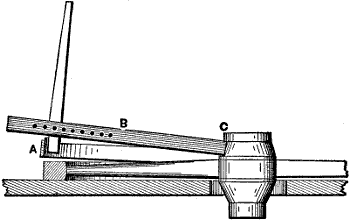
Fig. 1428.
Very slight bands may be forced on by levers: thus, wagon makers use a lever or jack, such as in Fig. 1428, for forcing the tires on their wheels. The wheel is laid horizontally on a table as shown, and the tire a forced out by the vertical lever, the arm b affording a fulcrum for the lever, and itself resting against the hub c of the wheel.
The following extracts are from a paper read by Thomas Wrightson, before the Iron and Steel Institute of Great Britain.
“The large amount of attention bestowed upon the chemical properties of metals, and the scientific methods adopted for their investigation, have led to the most brilliant results in the history of iron and steel industries. It must not, however, be overlooked that iron and steel have highly important properties other than those which can be examined by chemical methods. The cause for so little having been done in accurate observation of the physical properties of iron is twofold: 1. The molecular changes of the metals are so slow, when at ordinary temperatures and when under ordinary conditions of strain, that reliable observations, necessarily extending over long periods, are difficult to obtain: 2. When the temperatures are high—at which times the greatest and most rapid molecular changes are occurring—the difficulties of observation are multiplied to such an extent that the results have not the scientific accuracy which characterizes the knowledge we have of the chemical properties of metals.
“The object of the present paper is to draw attention to some phenomena connected with the physical properties of iron and steel, and to record some experiments showing the behavior of these metals under certain conditions.
“In experimenting the author has endeavored to adopt methods which would, as far as possible, eliminate the two great difficulties mentioned.
“It is obvious that the possible conditions under which experiments may be made are so numerous that all which any one experimenter can do is to record faithfully and accurately his observations, carefully specifying the exact conditions of each observation, and this must eventually lead to a more complete knowledge of the physical properties of the metals.
“The author’s observations have been led in the following directions:—
“1. The changes in wrought and cast iron when subjected to repeated heatings and coolings.
“2. The effect upon bars and rings when different parts are cooled at different rates.
“3. These changes occurring in molten iron when passing from the solid to the liquid state, and vice versâ.
PART I.
“To illustrate the practical importance of knowing the effects of reiterated heating and cooling on iron plates, one of the most obvious examples is the action of heat upon the plates of boilers which are alternately heated and cooled, as in use or otherwise. When in use, the plates above the fire are subjected to the fierce flame of the furnace on one side, and on the other side to a temperature approximating to that of the steam and water in the boiler. Where the conducting surfaces of the metal are thickened at the riveted seams, a source of danger is frequently revealed in the appearance of what are known as ‘seam-rips.’
“The long egg-ended boilers, much used in the North of England, are very subject to this breaking away of the seams. From some tests made by the writer on iron cut from the plates of two different boilers which had ripped at the seams, and one of which seam-rips had led to an explosion resulting in the destruction of much property, though happily of no lives, it was found that the heat acting on the bottom of the boiler had, through time, so affected the iron at the seam as to make it brittle, apparently crystalline in fracture, and of small tensile strength. Farther from the seam the iron appeared in both cases less injuriously affected. But although the alternate heating and cooling of the plates over a long period had produced this change in the molecular condition of the iron, a method of restoration presents itself in the process of annealing. In subjecting the pieces cut from the seam-rips to a dull red heat, and then allowing them to cool slowly in sawdust, the writer found that the fibrous character of the iron appeared again, and renewed testing showed that the ductility and tensile strength were restored.
“The same process of annealing is equally effectual in restoring the tenacity of iron in chains rendered brittle, and apparently crystalline, by long use, and is periodically applied where safety depends upon material in this form. Thus the heating and cooling of iron may be looked upon as the bane or the antidote according to the conditions under which the process is carried out. This affords an example of the importance of the physical effects produced by repeated changes of temperature. The change effected by one heating and cooling is so small that a cumulative method of experiment is the only one by which an observable result can be obtained, and this is the method adopted by the writer in the investigation now to be described.
“It is well known that if a wrought-iron bar be heated to redness, a certain expansion takes place, which is most distinctly observed in the direction of its length. It is also known, although not generally so, that if a bar be thus heated and then suddenly cooled in water, a contraction in length takes place, the amount of this contraction exceeding that of the previous expansion, insomuch that the bar when cooled is permanently shorter than it originally was. If this process of heating and cooling be repeated, a further amount of contraction is found to follow for many successive operations.
“Experiments Nos. 1 and 2 were made to verify this, and to show the increment of contraction after each operation.
“EXPERIMENTS ON WROUGHT-IRON BARS 11⁄8 IN. SQUARE BY 30.05 IN. LONG, HEATED TO A DULL RED, THEN COOLED SUDDENLY IN WATER.
Experiment No. 1. Experiment No. 2.
Common Iron. Best Iron.
Contraction. Percentage on original length. Contraction. Percentage on original length.
Inches. Inches.
After 1st cooling .04 .13 .04 .13
„ 2nd „ .10 .33 .10 .33
„ 3rd „ .16 .53 .14 .46
„ 4th „ .17 .56 .16 .53
„ 5th „ .23 .76 .20 .66
„ 6th „ .28 .93 .24 .80
„ 7th „ .31 1.03 .27 .89
„ 8th „ .33 1.10 .30 1.00
„ 9th „ .40 1.33 .33 1.10
„ 10th „ .47 1.56 .39 1.30
„ 11th „ .52 1.73 .42 1.40
„ 12th „ .54 1.80 .47 1.56
„ 13th „ .58 1.93 .51 1.70
„ 14th „ .62 2.06 .54 1.80
„ 15th „ .68 2.26 .56 1.86
“The Table of Experiment No. 5 shows that at the twenty-fifth cooling a contraction of 3.05 per cent. had taken place, or an average of .122 per cent. after each cooling. This is almost identically the same average result as shown in Experiment No. 1 with straight bars.
“The above experiments only having reference to the permanent contraction of the iron in the direction of its length, the author made the following experiments to ascertain the effect in the other dimensions, and to see whether the specific gravity of the iron was affected in the reduction of dimensions.
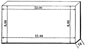
Fig. 1429.
“Experiment No. 6.—Wrought-iron plate, .74 inch thick, planed on both surfaces and all edges to a form nearly rectangular, and of the dimensions given in Fig. 1429.
“Specific Gravity.—Two small samples were cut out of different parts of the same piece of plate from which the experimental piece was planed, and the specific gravity determined as follows:—
No. 1 piece 7.629 } Mean, 7.64.
No. 2 piece 7.651
“Quality.—Subjecting a piece to tensile strain in the direction of the grain, it broke at 21.2 tons per square inch of section, the ductility being such that an elongation of 8.3 per cent. occurred before fracture, with a reduction of 9.6 per cent. of the area of fracture. This may be looked upon as representing a fairly good quality of iron.
“A bar of wrought iron, 11⁄8 inches square and 30.00 inches long, was heated to redness, and then allowed to cool gradually in air. Measurements after each of five coolings showed no perceptible change of length.
“Experiment No. 4.—Wrought-iron bar, 11⁄8 inches square by 30 inches long, heated to a white heat and cooling gradually in air.
Contraction. Percentage on original length. Remarks.
Inches.
After 1st cooling No change. ——
„ 2nd „ „ ——
„ 3rd „ .02 .07 ——
„ 4th „ .05 .17 ——
„ 5th „ .05 .17 ——
“It may be remarked, that if the bars be heated to white heat a slight contraction does occur, as shown by Experiment No. 4, where a bar of the same dimensions as No. 3 contracted .17 per cent. after the fifth cooling. As, however, the further remarks on this subject have only reference to bars heated to redness and then cooled, the writer would summarize the results of Experiments Nos. 1, 2, and 3, by stating that wrought-iron bars heated to redness permanently contract in their length along the fibre when cooled in water of ordinary temperature; but when cooled in air, they remain unchanged in length.
“To show that this is true as applied to circular hoops, Experiment No. 5 was made upon a wrought-iron bar of 11⁄8 inches square in section, welded into a circular hoop, 57.7 inches outside circumference.
“Experiment No. 5.—Wrought-iron hoop, 11⁄8 inches square by 57.7 inches outside circumference, heated to a dull red, then cooled suddenly in water.
Contraction. Percentage of original circumference. Remarks.
Inches.
After 1st cooling .06 .10 Red heat.
„ 2nd „ .06 .10 This was nearly white, but before cooling red hot.
„ 3rd „ .16 .28
„ 4th „ .26 .45
„ 5th „ .35 .61
„ 6th „ .46 .80
„ 7th „ .54 .93
„ 8th „ .60 1.04
„ 9th „ .68 1.18
„ 10th „ .76 1.32
„ 11th „ .80 1.38
„ 12th „ .87 1.51
„ 13th „ .94 1.63
„ 14th „ 1.00 1.73
„ 15th „ 1.08 1.90
„ 20th „ 1.30 2.25 On opposite edge 1.66; hoop splitting.
„ 25th „ 1.76 3.05
“This hoop was heated to redness and cooled in water twenty-five times, the circumference of the hoop being accurately measured after each cooling.[23]
“Two wrought-iron bars, 11⁄8 inches square and 30.05 inches long, were selected.[24] No. 1 was of common “Crown” quality; No. 2 of a superior quality known as “Tudhoe Crown.” These bars were heated to redness in a furnace and then plunged into water of ordinary temperature, the length being accurately measured after each cooling. After fifteen heatings and coolings the permanent contraction on No. 1 bar was 2.26 per cent. of the original length, and that on No. 2 bar 1.86 per cent., or an average on the two bars of about .13 per cent. after each cooling, the increment of contraction being nearly equal after each successive operation. It is noticeable that after the first two coolings the better quality of iron did not contract quite so much as the common quality, and that in the latter the contraction was going on as vigorously at the fifteenth as at the first cooling.
“Similar bars of wrought iron, heated to redness and then allowed to cool in air at ordinary temperature, do not appear to suffer any permanent change in their length.
“Experiment No. 3 was made to verify this.
“Experiment No. 3.—Wrought-iron bar, 11⁄8 inches square by 30 inches long heated to a dull red and cooled gradually in air.
Contraction. Percentage on original length. Remarks.
After 1st cooling No change. —— ——
„ 2nd „ „ —— ——
„ 3rd „ „ —— ——
„ 4th „ „ —— ——
„ 5th „ „ —— ——
Wrought iron rectangular plate. 14” thick × 11” 995 × 598 planed on both surface and edges. Heated to redness, and cooled in water 50 times. The dotted lines show original form, the black lines the form after the eperiment.
(Two-ninths of full size.)
Fig. 1430.
The plate was subjected to fifty heatings to redness and subsequent coolings in water of ordinary temperature. At every tenth cooling accurate measurements were taken of the contraction in superficial dimensions, and Fig. 1430 shows the final form after fifty coolings. The intermediate measurements at every tenth cooling showed a uniform and gradual decrease in the superficial dimensions, but the thicknesses were only measured after the fifty coolings had been completed. The thickness appears to have varied considerably; in some places, notably towards the centre and outside edges, being much reduced. Between the centre and outside edges the thickness appears to have increased, and in some few places the plate has been split open. The average dimensions in inches before and after the experiment were as follows (dimensions of cracks being allowed for):—
Average length. Average breadth. Average thickness. Cubic inches capacity.
Inches. Inches. Inches.
Original 11.99 5 5.98 .74 53.08
After 50 coolings 11.25 5.59 .77 4 48.72
Per cent. variation from original - Decrease Decrease Increase Decrease
of of of of
6.2 p. c. 6.52 p. c. 4.6 p. c. 8.2 p. c.
“Three triangular pieces of iron were then cut out of the plate from positions indicated on the diagram; No. 1a from the part most reduced in thickness, No. 3a from the part most increased in thickness, and No. 2a from a part where the thickness was a mean between the thickest and thinnest part. The specific gravities were accurately determined as follows:—
No. 1a 7.552 thinnest part.
No. 2a 7.574 average thickness.
No. 3a 7.560 thickest part.
“The average of these specific gravities is 7.562.
“The average before experiment was 7.64. Hence the average loss in specific gravity has been 1.02 per cent.
“The small triangular piece No. 1a, specific gravity 7.552 (already subjected to fifty heatings when forming part of the solid plate), was next heated and cooled fifty times more. The specific gravity at the end of the one hundred total coolings was 7.52, being .43 per cent. lower than after fifty heatings in plate, and 1.57 per cent. lower than 7.64, the original mean specific gravity of the plate.
“The same piece, 1a, was then heated twenty-five times more, making 125 in all. On taking the specific gravity it was found to be 7.526, or practically the same as after 100 total heatings and coolings.
“It thus appears that there is an undoubted decrease in specific gravity on repeated heating and cooling as described up to one hundred coolings, the specific gravity decreasing as much as 1.57 per cent.; that this percentage appears to be less when the pieces of iron operated upon are very small; that while there is a decrease of specific gravity there is also a decrease of total volume.
“From the above it was evident that the volume was affected by several causes:—
“1. By the permanent contraction of the outer skin, either the volume would be lessened, or relief by bulging out the sides must occur.
“2. By the decrease of specific gravity an increase of volume must occur, which could also find relief in bulging.
“3. A diminution of the whole mass must occur through scaling of the surface.
“Having determined the change in specific gravity by Experiment 6, we only now want to determine the loss of volume due to surface scaling, and we can then infer the actual contraction of the outer skin.
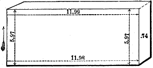
Fig. 1431.
“Experiment No. 7.—To ascertain the amount of scaling which took place in heating and cooling under same conditions as Experiment No. 6, a wrought-iron plate was cut from the same piece as No. 6, thickness .74 in., planed on both surfaces and all edges to a form nearly rectangular, and to the dimensions given in Fig. 1431.
“The only difference (except the very small difference in the dimensions) between this and 1430, was that the principal grain of the iron was in 1431 in the direction of the arrow, whereas in the other it was lengthwise of the plate.
“This piece was subjected to fifty heatings to redness and sudden coolings in water of ordinary temperature, as in the case of No. 6. The change in form was exactly the same in general character, but the contraction was not quite so great either in length or breadth; the increase in thickness, however, was proportionately greater, the volume (measured by displacement of water) after fifty heatings being 48.6 cubic inches, which is nearly the same as in No. 6 after the same number of heatings. The weight of the piece:—
Avoirdupois.
lbs. oz. dr.
Before heating 14 10 15
After fifty heatings 13 5 10
Difference 1 1 5
“This represents a loss of 9.07 per cent. of the original weight by scaling, and upon the whole original surface (sides and edges) represents a thickness of .0284 of an inch for the fifty immersions, or .00057 of an inch for the thickness of the film lost at each immersion over the whole surface.
“Calculating the weight of No. 6 before and after experiment from the volumes and specific gravities, we find the following:—
Volume. Mean specific gravity. Weight of cubic inch water. Pounds.
Weight before heating should be 53.08 × 7.64 × .036 = 14.599
„ after „ „ 48.72 × 7.56 2 × .036 = 13.262
Difference in weight 1.337
the ascertained difference in the case of No. 7 being 1.332, thus sufficiently accounting for the discrepancy between specific gravity and change of volume by the scaling.
“By Experiment 7 it has been shown that the loss of thickness due to scaling after fifty immersions was .0284 inch over the whole surface (sides and edges.) Therefore, assuming this scaling as uniform over the surface, the girth, whether measured lengthwise or breadthwise, should be eight times .0284, or .23 inch less after immersion than before. Now the gross loss of girth is:—
Lengthwise. Breadthwise.
Inches. Inches.
In No. 6 1.3 8 .86
In No. 7 1.2 .52
Or for both experiments a mean of 1.2 9 .69
Deducting from them the loss of girth due to scaling .2 3 .23
Net contraction after fifty immersions 1.0 6 .46
Or in percentage of original girths, which were 25.4 6 13.43
per cent. per cent.
We have a percentage of 4.1 6 3.42
Or for each immersion an average of .0 83 .07
“Comparing these results with those of Experiments Nos. 1, 2, and 5, we find that the contraction of the skin of the plate is less for each immersion than that of a bar or hoop, in the proportion of .125 to .083. This is what might be expected, as the contraction of the plate is resisted by the volume of heated matter inside, which is eventually displaced by bulging, while the bar finds relief endwise without having to displace the interior.
“We have now before us the following facts, substantiated by the experiments described:—
“1. That in heating to redness, and then cooling suddenly in water at ordinary temperatures, bars and plates of wrought iron, a reduction of specific gravity takes place, the amount being about 1 per cent. after fifty immersions, and 1.57 per cent. after one hundred immersions, further heatings and coolings not appearing to produce further change.
“2. That a reduction of the surface takes place after each heating and cooling, this being due to two causes:—
“a. The scaling of the surface, which is shown to amount to a film over the (sides and edges) entire area of .00057 inch in thickness for each immersion, or 0.284 inch for fifty immersions (Experiment 7).
“b. A persistent contraction, which takes place after each immersion. This varies according to the form of the iron, being in plates from .07 per cent. to 0.83 per cent. (Experiment 6), while in long bars it varies from .122 to .15 per cent. (Experiments 1, 2, and 5). This contraction continues vigorously up to fifty immersions, and probably much farther.