Volume 1 — Chapter VII.—DETAILS IN LATHE CONSTRUCTION. (continued 2)
Reading edition
An improvement on this form has been pointed out by Professor John E. Sweet, whose device is shown in Fig. 592. Here the washer or ring is rounded and the bottom surface of the gib is hollowed, so that chips or dirt will to a great extent fall off, and every time the tool post is swung the gib acts to push off whatever dirt may lodge on the washer.
In the design shown in Fig. 593, the tool rests upon two washers w that are tapered, and its height is adjusted by revolving one of these washers, it being obvious that the limit of action to depress the tool point is obtained when the two thin sides of the washers are placed together, and on the same side of the tool post as the cutting edge of the tool, while the limit of action to raise the tool point is obtained when the washers have their thick sides together and nearest to the tool point.
Here again the tool is thrown out of level, and to obviate this difficulty the stepped washer shown in Fig. 594 may be used, the steps on opposite sides of the washer being of an equal height. This enables the tool to be raised or lowered without being set out of the horizontal position; but it has the defect that the adjustment cannot be made any finer than the height of the steps, and if the height is made to vary but slightly, in order to refine, as it were, the adjustment, the range of tool elevation or depression is correspondingly limited. Another form of stepped washer is shown in Fig. 595, in which no two steps are of the same height. This affords a wider range of adjustment, because the same two steps will alter the height of the tool by simply turning the washer one-half revolution. It has two defects, however; first, the least amount of adjustment is that due to the difference in height of the steps; and, second, when the tool is elevated it grips the washer at a, so that the tool is not supported across the full width of face of the washer, as it should be.
A defect common to all devices in which the tool is thrown out of level, is that the binding screw does not bed fair upon the tool, and as a result it is apt, if screwed home very firmly, as is necessary to hold boring tools that stand far out from the tool post, to spread the screw end as in Fig. 596, or to bend it.
A very convenient tool-adjusting device is shown in Fig. 597. It consists of a threaded ring n receiving the threaded bush m, the tool height being adjusted by screwing or unscrewing one within the other.
The objection to this is, that it occupies so much vertical height that there is not always room to admit it, which occurs, for example, in compound slide rests on small lathes.
On these rests, therefore, a single washer is more frequently used, which answers very well when the tool post is in a slot, so that it can be moved from side to side of the rest as occasion may require. When, however, the position of the tool post is fixed it has the disadvantage that the point p, Fig. 598, where the tool takes its leverage, is too far removed, and the tool is therefore liable to bend or spring from the pressure of the cut.
In Fig. 599 is an elevating device sometimes used on the compound rests of large lathes. The top of the rest is provided with a hub h, threaded externally to receive a ring nut r, around whose edge there are numerous holes to receive a pin for operating the nut. The tool-post is situated central in the hub. When the tool is loose the ring nut can be operated by hand or the tool may be gripped lightly and the ring nut operated by a pin. The level of the tool is here maintained; it is supported to about the edge of the rest on account of the large diameter of the ring nut, and a very delicate adjustment for height can be made, but such a device is only suitable for large lathes on account of the depth of the ring nut and hub.
On small slide-rests the device shown in Fig. 600 is often found. It consists of a holder h, in which is cut a seat for the tool, this seat being inclined to give the piece of steel used as a tool a certain constant degree of angle, and at the same time to permit of the tool being moved endwise in the holder to set it for height; but, as the tool requires to be pushed farther and farther through the holder to raise it, it is not so well supported as is desirable when slight tools are used, unless the holder is made long, so as to pass through the tool post with the tool. Again, it does not support the tool sideways unless the tool steel is dressed up and closely fits the groove in the holder.
In Fig. 601 w w are two inverted wedges which afford an accurate adjustment, but the range is limited, because if the wedges have much taper they are apt to move endways when the tool is fastened.
A convenient device for the compound rests of small lathes is shown in Fig. 602. It consists of a holder pivoted upon a central post and carrying two tool-binding screws, hence it can be revolved to set the tool in any required position. A similar device is shown in Fig. 603, in which the central post is slotted at a to receive the tool, and also carries a plate c, held by the nut n, and provided with tool-holding screws b and b′, which abut against the top of the rest, a top view of the device being shown in Fig. 604. Plate c may thus be swung around to set the tool in any required position on either side of the rest.
In Maudslay’s slide rest, the tool clamp shown in Fig. 605 is employed. Screws a are employed to grip the tool moderately firm, and a turn of screws b (whose ends abut against the top of the slide rest) very firmly secures the tool, since it moves the clamp c as a lever, whose fulcrum is the screw a.
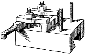
Fig. 607.
Figs. 606 and 607 represent the Whitworth tool clamp, the clamping plates of which change about upon the four studs, and are supported at their inner ends by a block equal in height to the height of the tool steel.
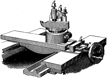
Fig. 608.
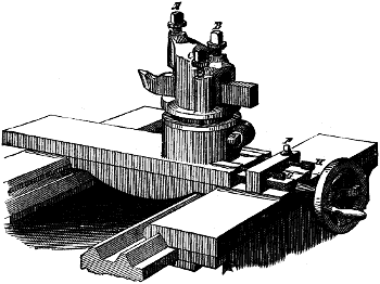
Fig. 609.
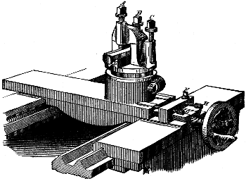
Fig. 610.
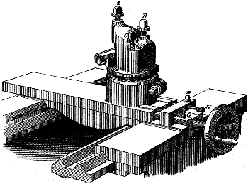
Fig. 611.
Figs. 608, 609, 610, and 611 represent the “Lipe” tool post, so called from the name of its inventor. The top of the cross slide is cylindrical, and is bored to receive the tool post which has a cylindrical stem. The cylindrical part of the tool post is split vertically, and has two lips, the bolt d passing through one lip and threading into the other, so that by operating bolt d the tool post may be gripped very firmly or released, so that it may be revolved to bring the tool into any required position after it is fastened in the tool post, which is a great advantage because the tool is brought to a solid seating in the post before its height is adjusted, and will not therefore be altered in height by setting up the set screws as often occurs in ordinary tool posts. From the shape of the tool post, the tool may be gripped by one set screw only, when required for light duty, or by two set screws for heavy duty or for boring, while in either case it is supported clear to the edge of the rest.
Fig. 608 shows the tool in position, held by a single screw, for work requiring the tool to be close up to the work driver. In Fig. 609 a tool is shown held as is required by work between centres, but both set-screws are used. Fig. 610 shows a tool in position for boring, two set-screws being used. Fig. 611 shows a tool being held for the same purpose, but by a single screw, and it will be observed that the advantage of the second set-screw is obtained without in any way sacrificing the handiness of the post, when used with a single screw. Whether one or two set-screws are used, the boring tool may be forged from a single bar of octagon steel, which can be seated in a piece like that shown at e in Fig. 610, which is grooved so as to receive and hold the tool. As is well known, boring tools are the most troublesome both to forge and to adjust in the lathe, and, as the result, a light tool is often used because no other is at hand and it is costly to make a new one. When, however, the tool can be forged from a plain piece of steel, these objections are overcome, and a sufficient number of tools may be had so that one can always be found suitable for any ordinary sized hole, the object being to use as rigid a tool as can be got into the hole bored. The feature of maintaining the tool level is of great importance in boring work, because when the tool requires to be set out of level to adjust its height, it will generally strike against the mouth of the hole if the latter is of much depth. This annoyance is also frequently met with in boring tools which are forged out of rectangular steel, because the rounded stem is generally left taper. The largest end of the taper is generally nearest the tool post. Hence the capacity to use octagon steel and keep it level while adjusting its height, added to the fact that the tool is supported clear to the edge of the tool rest, and the tool post is so blocked as to virtually become a part of the rest, constitute a very important advantage.
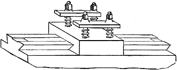
Fig. 612.
A common device on large lathes is shown in Fig. 612, the two clamps being shown in position for outside turning, and being changed (so as to stand at a right angle to the position they occupy in the figure) for holding boring tools. The bolts are enveloped by spiral springs which support the clamps.
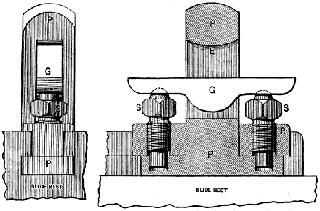
Fig. 613.
Figs. 613 and 614 represent the tool holders employed in the Brown and Sharpe small screw machines. In the front rest, Fig. 613, the piece r receives two adjusting and tool-gripping screws s, upon which sits the gib g, and upon this the tool is placed. The surface e at the top of the tool post slot is curved so that it will bear upon the top of the tool at a point only. The tool is here supported along the full length of the gib, and there is no set-screw at the top of the tool post, which enables a much more unobstructed view of the tool.
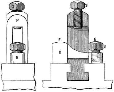
Fig. 614.
Fig. 614 is the tool post used at the back of the rest, the piece b passing through the tool post slot. The tool rests upon the top of screw e and upon the top of b at f, and is secured by set-screw s; its height is therefore adjusted by means of screw e, which is threaded in b. The set-screw s is not in this case objectionable, because it is at the back of the rest, and therefore does not obstruct the view of the work, while it is at the same time convenient to get at.
When the screw for traversing a lathe carriage is used for plain feeding, it is termed the feed screw, but when it is used to cut threads it is termed the lead screw.
A lead screw should be used for screw cutting only, so that it may be preserved as much as possible from wear. As the greater portion of threads cut in a lathe of a given size are short in comparison with the length of the lathe, it follows that the part of the lead screw that is in operation when the carriage or saddle is traversing over short work is most worn, while the other end is least worn, hence it is not unusual to so construct the screw and its bearings that it may be changed end for end in the lathe, to equalize the wear. By turning a lead screw end for end, therefore, to equalize the wear, the middle of the length of the screw will become the least worn, and, therefore, the most true. Hence it is better to use one end of the lead screw for general work, and to reverse it and use the other end only for screws requiring to be of very correct pitch.
To obviate the wear as much as possible the feed nut should embrace as great a length of the screw as convenient, and should be of a material that will suffer more from wear than the lead screw, or in other words shall relieve the feed screw from wear as much as possible. The wear on the nut being equal from end to end, the wearing away of one side of its thread does not vary its pitch; hence the only consideration as to its wearing qualification are the expense of its renewal and the length of time that may occur between its being engaged with the lead screw and giving motion to the lathe carriage, this time increasing in proportion as the nut thread is worn. Under quick speeds or when the lathe is in single gear, the rotation of the feed screw is so quick that not much time is lost before the carriage feeds, but when the back gear is in operation at the slowest speeds, the loss of time due to a nut much worn is an item of importance.
In some lathes the feed screw is employed for screw cutting and for operating an independent feed also. This is accomplished by cutting a feather way or spline along it, so that a worm having journal bearing in the apron of the rest carriage may envelop the lead screw and be driven by it, through the medium of a feather fast into the worm gear. The motion obtained from the worm gear is transferred through suitable gearing to the rack pinion.
The spline is cut deeper than the thread, so as to prevent the latter as far as possible from wear, by reason of the friction of the spline.
The lead screw if long should be supported, to prevent its sagging of its own weight. In some cases the lead screw is supported in a trough along its whole length, as is done in the Sellers lathe. In other cases, bearings hanging from the V-slides, and movable along the bed, are employed.
It is desirable that the feed screw and nut be as near the middle of the carriage as possible, so that it shall pull the carriage at as short a leverage as possible, thus avoiding the liability to tilt or twist the carriage; but it is not practicable to place it midway between the lathe shears, because in that case the cuttings, &c., from the work would fall upon it, and cause excessive and rapid wear of the screw and nut.
In general the lead screw is located either in front, or at the back of the lathe, and in considering the more desirable of the two locations, we have as follows:
The feed nut should obviously remain axially true with the lead screw, as by reason of the extra weight of the front of the carriage, both it and the lathe shears wear most at the front, and the carriage, therefore, falls to the amount of its own wear and the wear of the shears. If the lead screw is used to feed with (as it should not be), the nut wears coincidently with the carriage and the shears, and the screw alignment is not impaired; but with an independent feed, only a small portion of the carriage traversing is done with the lead screw, hence the carriage lowers from the wear due to the independent feeding, and when the lead screw comes to be used its nut is not in true alignment with it. It is obviously preferable, then, to place the lead screw at the back, where the carriage and shears wear the least. Furthermore, this relieves the carriage front from the weight of the nut, &c., tending to equalize the back and front wear, while removing the nut-operating device from the front to the back of the shears, and thus reducing the number of handles in front, and thus avoid complication in small lathes.
Lathe Lead Screws.—Lead screws have their pitches in terms of the inch throughout all parts of the world; or, in other words, the lead screws of all lathes contain so many full threads per inch of length.
Lead screws are usually provided with square threads of the usual form, or with threads whose sides have about fifteen degrees of angle, so that the two halves of the feed nut may be let together to take up the wear. It is obvious that in a V-thread or in a thread whose sides are at an angle, the feeding strain tends to force the two halves of the feed nut apart, and therefore places a strain on the feed-nut operating mechanism that does not exist in the case of a square thread. Furthermore it can be shown that with a V-thread the opportunities to lock the carriage on a wrong place, after traversing it back by hand in screw cutting, are increased, thus augmenting the liability to cut intermediate and improper threads.
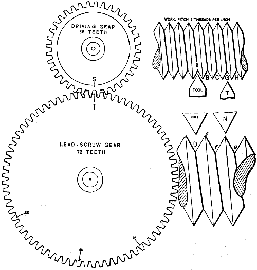
Fig. 615.
In Fig. 615, for example, we have a pitch of lead screw of three threads per inch, and the gears arranged to cut six threads per inch on the work. As the bottom wheel has twice as many teeth as the top one, it is clear that, while the top one makes one, the bottom one will make half revolution, and the lead screw will make half a turn for every turn the work makes. Now, suppose the tool point to stand opposite to space a, and the nut (supposing it to have but one thread only, which is all that is required for our purpose), stand opposite to space d. Suppose, further, that the lathe makes one revolution, and space b on the work will have moved to occupy the position occupied by space a, or, rather, there will still be a place at a fully in front of the tool, as should be the case, but the lead screw will have made half revolution, the top e of the thread coming opposite to the feed nut, as in the position of tool and nut shown in the figure at t and n; hence the nut would not engage, without moving the lathe carriage sideways, and thus throwing the tool to one side of the thread in the work. When, however, the work had made another revolution, both the feed screw and the work would again come into position for the tool and nut to engage properly, and it follows that in this case the tool will always fall into proper position for the nut to be locked.
It is obvious, however, that had the lead screw thread been a square one, and the nut thread to accurately fit to the lead screw thread, so as to completely fill it, then the nut could not engage with the lead screw until the lathe had made a complete revolution, at which time the work will have made two full or complete revolutions, and the tool would, therefore, fall into proper position to follow in the groove or part of a thread cut at the first tool traverse.
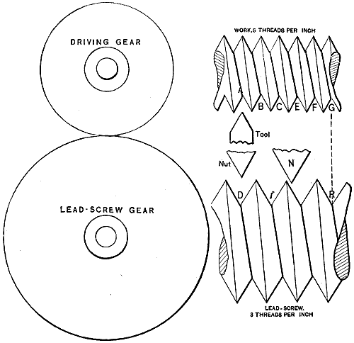
Fig. 616.
In Fig. 616, we have the same lead screw geared to cut five or an odd number of threads per inch. The tool and the nut are shown in position to properly engage, but suppose, the nut being disengaged, that the work makes one revolution, and during this period the lead screw will have made 3⁄5ths of a revolution, hence the nut will not be in position to engage properly, because, although space b will have travelled forward so as to occupy the position of space a in the figure (that is, there will be a space fairly in front of the tool point), yet the nut will not engage properly, because the nut point will not be opposite to the bottom of the lead screw thread. When the work has made its second revolution, and space c moves to the position occupied by a, the lead screw will have made 6⁄5 or 11⁄5 revolutions, and the nut cannot engage properly; when the lathe has made its third revolution, the lead screw will have made 14⁄5 revolutions and the nut will still fall to one side of the thread space, and will not lock properly. The work having made its fourth turn, the lead screw will have made 22⁄5 turns, and the nut will not be in position to lock fairly. The work having made its fifth turn, however, the lead screw will have made three turns, and the threads will fall into the same position that they occupy in the figure, and both tool and feed nut will fall into their proper positions in their respective threads. It does not follow, however, that, the lead screw having a V-shaped thread, the nut cannot be forced to engage but once in every five turns of the lead screw, because, were this the case, it would be impossible to lock the nut in an improper position.
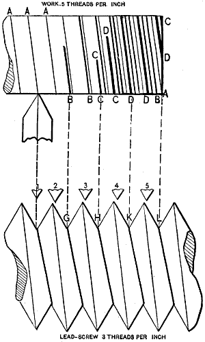
Fig. 617.
Suppose, for example, that we have in Fig. 617, the same piece of work and lead screw as in Fig. 616, and that a first groove, a, has been cut with the tool in the position shown, and the nut engaged in the position marked 1. Now, suppose the nut be disengaged and the work allowed to make one revolution, then the lead screw will, during this revolution, revolve 3⁄5 of a revolution, and the position of the nut point with relation to the lead screw will be as at position 2. If, then, the nut was forced into the lead screw thread, it would, acting on the wedge principle, move the carriage to the right sufficiently to permit the nut to engage fully in thread g, and the tool would then cut a second groove on thread b. If the nut then be withdrawn from thread g, and the work allowed to make another revolution, the nut will stand in a precisely similar position with relation to the lead screw thread as it did in position 2, and by forcing it down into thread h the carriage would be again forced to the right, causing a third thread, c, to be cut. By repeating the operation of withdrawing the nut, letting the work make another revolution and then engaging the nut again, it will seat in thread k, and a fourth thread d will be cut. On again repeating the operation, however, the nut will come into position 5, and, on being drawn home into thread, or, rather, into space l, the tool will fall into groove a again. Thus there will be four threads, each having a pitch equal to that of the lead screw. The second (b) of these four will fall to the left of thread a to an amount or distance equal to 2⁄5 of the pitch of the lead screw, because, in forcing the nut from position 2 down into the lead screw, the slide rest, and therefore the tool, will be moved to the right 2⁄5 of the pitch of the lead screw. The third thread c will fall to the left of thread b also to an amount equal to 2⁄5 of the pitch of the lead screw, because, in forcing the thread to seat itself into thread h from position 3, the slide rest was again moved (to that amount) to the right. The fourth thread d will fall to the left of thread c to the same amount and for the same reason.
But in this case, as before, if the lead screw had a square thread and the nut threads completely filled the spaces between the lead screw threads, then the nut could not engage at the 2nd, 3rd, or 4th work revolution, hence the false threads b, c, and d, could not have been cut, even though the feed nut was disengaged and the lathe carriage was traversed back by hand.
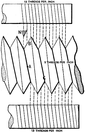
Fig. 618.
Now, suppose that two threads on the work measure less than the amount the lead screw advances during the time that the work makes a revolution, and if the lead screw has a V-shaped thread, the case is altered. We have, for example, in Fig. 618, a pitch of lead screw of 3 to cut 12 and 13 threads respectively. In the case of the 13 threads it will be seen that, supposing there to have been a first cut taken on the work, and the feed nut to be disengaged while the work makes a revolution, then the lead screw will revolve 3⁄13 revolution and the point a on the lead screw will have moved up to point b, and the nut point remaining at n, seating it in the thread, would cause it to engage with the same thread that it did before, and no second thread would be cut. If the nut be then released, the work allowed to make another revolution and the nut again closed, the operation would be the same as before, and no error would be induced, and so on. Suppose, further, that after the nut was disengaged the lathe was permitted to make two revolutions, and the lead screw would make 6⁄13, or less than half a turn, and closing it would still cause it to pass back into the same thread on the lead screw and produce correct work. But if after the nut was released the work made three turns, the lead screw would make 9⁄13 of a turn, and the nut would fall on the right-hand side of the lead screw thread, and in closing would move the lathe carriage to the right, causing the tool to cut a second thread. Now, the same operation that occurred with the first thread would during the next three trials occur with the second thread, and at the next or seventh trial a third thread would be cut, which would be again operated upon during the next succeeding three trials. At the eleventh trial a fourth thread would be cut, but on the next three trials the tool would again fall into the groove first cut and the work proceed correctly. In the case of the 12 threads, the thread cut at the first and second trials would be correct. At the third trial the nut would seat itself in the groove c of the lead screw, causing the carriage to move to the right to a distance equal to twice the pitch of thread being cut, but the tool would still fall into the same groove in the work, as it also would on the fourth. At the fifth trial the process would be repeated, and so on, so that no second thread would be cut.
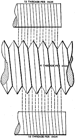
Fig. 619.
It may now be noted that if we draw the lead screw and the thread to be cut as in the figure, and draw the dotted lines shown, then those that meet the bottom of the thread on the lead screw, and also meet the groove cut on the work, at the first trial, represent the cases in which the nut will fall naturally into its proper position for the tool to fall into the correct groove, while whenever the nut is being forced home it seats in a groove in the lead screw, the bottom of which groove meets a line drawn from the first thread cut; the results obtained will be made correct by reason of the movement given to the slide nut when artificially seating the nut. This is shown to be the case in Fig. 619, which represents a lead screw having an even number of threads per inch, and from which it appears that in cutting 12 threads (an even number also) the nut cannot be engaged wrong, whereas in the case of 13 threads it can be engaged right three times in 13 trials, and 10 times wrong, the latter causing the tool to cut three wrong threads.
To prevent end motion of a lead screw it should have collars on both sides of one bearing, and not one at each bearing. By this means the screw will be permitted to expand and contract under variations of atmospheric temperature, without binding against the bearing faces.
When a lead screw is long it requires to be supported, otherwise, either its weight will be supported or lifted by the feed nut in gear, or if that nut does not lift the screw, the thread cut will be finer than that due to the pitch of the lead screw, by reason of its deflection or sag.
A lead screw should preferably be as near as possible to the middle of the lathe shears, and as close to the surface as possible, so as to bring it as nearly in line with the strain on the tool as possible, but on account of the cuttings, which falling upon the screw would cause it to wear rapidly, it is usual to locate it on one side, so as to protect it from the cuttings. It is better to locate it on the front side of the lathe rather than on the back, because the strain of the cut falls mainly on the front side (especially in work of large diameter when this strain is usually greatest) and it is desirable to pull the carriage as near in a line with the resistance of the cut as possible, because the farther off the feed nut from the cutting tool point, the greater the tendency to twist the carriage on the shears.
To preserve the nut from wear, it should be made as long as convenient, as, say, five or six times the diameter of the lead screw; it is usually made, however, three or four diameters.
It is obvious that the pitch of the thread should be as accurate as possible, but it has not as yet been found practicable to produce a screw so accurate that it would not show an error, if sufficient of its length be tested, as, say, several feet.
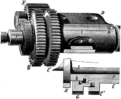
Fig. 620.
If the error in a screw be equal, and in the same direction at all parts of its length, various devices may be employed to correct it. Thus Fig. 620 represents a device employed by the Pratt and Whitney Co.
It was first ascertained by testing the lathe that its lead screw was too short by 7⁄100ths of a revolution in a length of 2 feet, the pitch of its thread being 6 to an inch. Now in 2 feet of the screw there would be 144 threads, and since 7⁄100ths (the part of a revolution the thread was too short) × 1⁄6 (the pitch of the thread) = 7⁄600ths (which was called 1⁄85th), the error amounted to 1⁄85th inch in 144 turns of the screw. The construction of the device employed to correct this error is as follows: In Fig. 620, a represents the bearing of the feed screw of the lathe, and b b a sleeve, a sliding fit upon a, prevented from revolving by the pin h, while still having liberty to move endways. c represents a casing affording journal bearing to b b, having a fixed gear-wheel at its end c′, and an external thread upon a hub at that end. d is the flange of c to fasten the device to the shears of the latter, being held by screws. e represents an arm fast upon the collar of the feed screw, and carrying the pinion f, the latter being in gear with the pinion c′, and also with g, which is a pinion containing two internal threads, one fitting to b at b, and the other fitting to c at c, the former having a pitch of 27 threads to an inch, the latter a pitch of 25 to an inch.
The operation is as follows:—The ordinary change wheels are connected to the feed screw, or lead screw, as it is sometimes termed, at j in the usual manner. The arm e being fast to the feed screw will revolve with it, and cause the pinion f to revolve around the stationary gear-wheel c′. f also gears with g. Now, f is of 12 diametrical pitch and contains 26 teeth, c′ is of 12 diametrical pitch and contains 37 teeth, and g is of 12 diametrical pitch and contains 36 teeth. It follows that the pinion f, while moving around the fixed gear c′, will revolve the pinion g (which acts as a nut), to an amount depending upon the difference in the number of its teeth and those of fixed gear c′ (in this case as 36 is to 37), and upon the difference in the pitches of the two threads, so that at each revolution g will move the feed screw ahead of the speed imparted by the change gears, the end of the sleeve b abutting against the collar of the feed screw to move it forward.
In this case there are 36 turns of the feed screw a for one turn of the nut pinion g, the thread on sleeve b being 27, and that on the hub of c being 25 to the inch; hence, 36 turns of the feed screw gives an end motion to the sleeve b of 1⁄25 minus 1⁄27 = 2⁄675, and 1⁄36 of that = 1⁄12150 of an inch = the amount of sliding motion of the sleeve b, for each revolution of the lathe feed screw. By varying the proportions between the number of teeth in c′ and g and the pitches of the two threads in a proper and suitable ratio, the device enables the cutting of a true thread from any untrue one in which the variation is regular.
It is usual to fasten to the side of the lathe head stock a brass plate, giving a table of threads, and the wheels that will cut them, and obviously such tables vary according to the pitch of the lead screw, but a universal table may be constructed, such as the following table (prepared by the author) that will serve for any lathe.
At the top of the table is the number of teeth in wheels, advancing by four from 12 to 80 teeth, but it may be carried as much beyond 80 as desired. On the left hand of the table is a column of the same wheels. At the bottom of the scale are pitches of lead screw from 3 up to 20 threads per inch. Over each lead screw pitch are thread pitches, thus on lead screw pitch 4 we have 20, 19, 18, and so on.
NUMBERS OF TEETH FOR WHEEL TO GO ON LATHE SPINDLE, LATHE STUD, OR MANDRIL.
Lead Screw. 12 *16 20 24 28 32 36 40 44 48 52 56 60 64 68 72 76 80
12 3 3 3 3 3 3 3 3 3 3 3 3 3 3 3 3 3 3
16 4 4 4 4 4 4 4 4 4 4 4 4 4 4 4 4 4 4
20 5 5 5 5 5 5 5 5 5 5 5 5 5 5 5 5 5 5
24 6 6 6 6 6 6 6 6 6 6 6 6 6 6 6 6 6 6
28 7 7 7 7 7 7 7 7 7 7 7 7 7 7 7 7 7 7
32 8 8 8 8 8 8 8 8 8 8 8 8 8 8 8 8 8 8
36 9 9 9 9 9 9 9 9 9 9 9 9 9 9 9 9 9 9
40 10 10 10 10 10 10 10 10 10 10 10 10 10 10 10 10 10 10
44 11 11 11 11 11 11 11 11 11 11 11 11 11 11 11 11 11 11
48 12 12 12 12 12 12 12 12 12 12 12 12 12 12 12 12 12 12
*52 13 13 13 13 13 13 13 13 13 13 13 13 13 13 13 13 13 13
56 14 14 14 14 14 14 14 14 14 14 14 14 14 14 14 14 14 14
60 15 15 15 15 15 15 15 15 15 15 15 15 15 15 15 15 15 15
64 16 16 16 16 16 16 16 16 16 16 16 16 16 16 16 16 16 16
68 17 17 17 17 17 17 17 17 17 17 17 17 17 17 17 17 17 17
72 18 18 18 18 18 18 18 18 18 18 18 18 18 18 18 18 18 18
76 19 19 19 19 19 19 19 19 19 19 19 19 19 19 19 19 19 19
80 20 20 20 20 20 20 20 20 20 20 20 20 20 20 20 20 20 20
Lead Screw Pitch 3. Lead Screw Pitch 4. Lead Screw Pitch 5. Lead Screw Pitch 6. Lead Screw Pitch 7. Lead Screw Pitch 8. Lead Screw Pitch 9. Lead Screw Pitch 10. Lead Screw Pitch 11. Lead Screw Pitch 12. Lead Screw Pitch 13. Lead Screw Pitch 14. Lead Screw Pitch 15. Lead Screw Pitch 16. Lead Screw Pitch 17. Lead Screw Pitch 18. Lead Screw Pitch 19. Lead Screw Pitch 20.
The use of the table is as follows:—
Find the pitch of the lead screw, and at the head of that column is the number of teeth for the lathe stud or mandril. Then find in that column the number of threads to be cut, and on the same line, but at the left hand, will be found the number of teeth for the lead screw.
Example.—The lead screw has a pitch of 4, and I require to cut 13 threads per inch. At the head of the column is 16, and on a line with the 13 of the column, but on the left is 52, each number being marked by a * hence the 16 and 52 are the wheels; if we have not those wheels, multiply both by 2 and 32, and 104 will answer.
If the pitch of the lead screw is 2 threads per inch, the wheels must advance by 6 teeth, as indicated below:—
NUMBERS OF TEETH FOR WHEEL TO GO ON LATHE STUD, LATHE SPINDLE OR MANDRIL.
Number of Teeth for Wheel to go on Lead Screw. Lead Screw. 12 18 24 30 36 42 48 54 60 66 72 78 84 90 96
12 2 2 2 2 2 2 2 2 2 2 2 2 2 2 2
18 3 3 3 3 3 3 3 3 3 3 3 3 3 3 3
24 4 4 4 4 4 4 4 4 4 4 4 4 4 4 4
30 5 5 5 5 5 5 5 5 5 5 5 5 5 5 5
36 6 6 6 6 6 6 6 6 6 6 6 6 6 6 6
42 7 7 7 7 7 7 7 7 7 7 7 7 7 7 7
48 8 8 8 8 8 8 8 8 8 8 8 8 8 8 8
54 9 9 9 9 9 9 9 9 9 9 9 9 9 9 9
60 10 10 10 10 10 10 10 10 10 10 10 10 10 10 10
Pitch of Lead Screw. 2 3 4 5 6 7 8 9 10 11 12 13 14 15 16
This table may be used for compound lathes by simply dividing the pitch of the lead screw by the ratio of the compounded pair of wheels. For example, for the wheels to cut 8 threads per inch, the pitch of lead screw being 4 and the compounded gears 2 to 1, as the ratio of the compounded pair is 2 to 1, we divide the pitch of lead screw by 2, which gives us 2, and we thus find the wheels in the column of pitch of lead screw 2, getting 12 and 48 as the required wheels, the 12 going on top of the lathe because it is at the top of the table, and the 48 on the lead screw because it is at the left-hand end of the table, and the lead screw gear is at the left-hand end of the lathe.
The table may be made for half threads as well as whole ones by simply advancing the left-hand column by two teeth, instead of by four, thus:—
Teeth for Wheel on Lead Screw. Teeth for Wheel on Stud.
12 16 20 24 28 32 36 40 44
12 3 3 3 3 3 3 3 3 3
14 3 1⁄2 3 1⁄2 3 1⁄2 3 1⁄2 3 1⁄2 3 1⁄2 3 1⁄2 3 1⁄2 3 1⁄2
16 4 4 4 4 4 4 4 4 4
18 4 1⁄2 4 1⁄2 4 1⁄2 4 1⁄2 4 1⁄2 4 1⁄2 4 1⁄2 4 1⁄2 4 1⁄2
20 5 5 5 5 5 5 5 5 5
22 5 1⁄2 5 1⁄2 5 1⁄2 5 1⁄2 5 1⁄2 5 1⁄2 5 1⁄2 5 1⁄2 5 1⁄2
24 6 6 6 6 6 6 6 6 6
26 6 1⁄2 6 1⁄2 6 1⁄2 6 1⁄2 6 1⁄2 6 1⁄2 6 1⁄2 6 1⁄2 6 1⁄2
28 7 7 7 7 7 7 7 7 7
30 7 1⁄2 7 1⁄2 7 1⁄2 7 1⁄2 7 1⁄2 7 1⁄2 7 1⁄2 7 1⁄2 7 1⁄2
32 8 8 8 8 8 8 8 8 8
34 8 1⁄2 8 1⁄2 8 1⁄2 8 1⁄2 8 1⁄2 8 1⁄2 8 1⁄2 8 1⁄2 8 1⁄2
36 9 9 9 9 9 9 9 9 9
38 9 1⁄2 9 1⁄2 9 1⁄2 9 1⁄2 9 1⁄2 9 1⁄2 9 1⁄2 9 1⁄2 9 1⁄2
40 10 10 10 10 10 10 10 10 10
42 10 1⁄2 10 1⁄2 10 1⁄2 10 1⁄2 10 1⁄2 10 1⁄2 10 1⁄2 10 1⁄2 10 1⁄2
Pitch of Lead Screw. 3 4 5 6 7 8 9 10 11
For quarter threads we advance the left-hand column by one tooth, or for thirds of threads by three teeth, and so on.
If we require to find what wheels to provide for a lathe, we take the pitch of the lead screw for the numerator, and the pitch required for the denominator, and multiply them first by 2, then by 3, then by 4, and so on, continuing until the numerator or denominator is as large as it can be to give the required proportion of teeth, and not exceed the greatest number that the largest wheel can contain.
For example: A lathe has single gear, and its lead screw pitch is 8 per inch, what wheels will cut 18, 17, 16, 15, 14, or 13 threads per inch?
Wheels.
Pitch of lead screw 8 × 2 = 16 24 32
Pitch required 18 36 54 72
Pitch of lead screw 8 „ 16 24 32
Pitch required 17 34 51 68
Pitch of lead screw 8 „ 16 24 32
Pitch required 16 32 48 64
Pitch of lead screw 8 „ 16 24 32
Pitch required 15 30 45 60
Pitch of lead screw 8 „ 16 24 32
Pitch required 14 28 42 56
Pitch of lead screw 8 „ 16 24 32 40
Pitch required 13 26 39 52 65
If we suppose that the greatest number of teeth permissible in one wheel is not to exceed 100, then in this table we have all the combinations of wheels that can be used to cut the given pitches; and having made out such a table, comprising all the pitches to be cut, we may select therefrom the least number of wheels that will cut those pitches. The whole table being made out it will be found, of course, that the numerators of the fractions are the same in each case; that is, in this case, 16, 18, 24, 32, and so on as far as we choose to carry the multiplication of the numerator. We shall also find that the denominators diminish in a regular order: thus taking the fractions whose numerators are in each case 16, we find their denominators are, as we pass down the column, 36, 34, 32, 30, 28, and 26, respectively, thus decreasing by 2, which is the number we multiplied the left-hand column by to obtain them. Similarly in the fractions whose numerators are 24, the denominators diminish by 3, being respectively 54, 51, 48, 45, 42, and 39; hence the construction of such a table is a very simple matter so far as whole numbered threads are concerned, as no multiplication is necessary save for the first line representing the finest pitch to be cut.
For fractional threads, however, instead of using the pitch of the lead screw for the numerator, we must reduce it to terms of the fraction it is required to cut. For example, for 51⁄2 threads we proceed as follows. The pitch of the lead screw is 8, and in 8 there are 16 halves, hence we use 16 instead of 8, and as in the 51⁄2 there are 11 halves we use the fraction 16⁄11 and multiply it first by 2, then by 3, and then by 4, and so on, obtaining as follows: 16⁄11, 32⁄22, 48⁄33, 64⁄44, obtaining as before three sets of wheels either of which will cut the required pitch. In selecting from such a table the wheels to cut any required number of pitches, the set must, in order to cut a thread of the same pitch as the lead screw, contain two wheels having the same number of teeth.
Now, suppose that the pitch of the lead screw was 6 instead of 8 threads per inch, and the table will be as follows:—
6 12 18 24
18 36 54 72
6 12 18 24
17 34 51 68
6 12 18 24
16 32 48 64
6 12 18 24
15 30 45 60
6 12 18 24
14 28 42 56
6 12 18 24
13 26 39 52
Here, again, we find that in the first vertical column the denominators decrease by two for each thread less per inch, in the second column they decrease by three, and in the third by four; this decrease equalling the number the first fraction was multiplied by.
But suppose the lead screw pitch is an odd one, as, say, 3 threads per inch, and we construct the table as before, thus—
Pitch of lead screw 3 6 9 12 15
Pitch to be cut 18 32 54 72 90
Now it is useless to multiply by 2 or by 3, because they give a less number of teeth than the smallest wheel should have, hence the first multiplier should be 4, giving the following table:—
3 12 15 18
18 72 90 108
3 12 15 18
17 68 85 102
3 12 15 18
16 64 80 96
3 12 15 18
15 60 75 90
By continuing the table for other pitches we shall find that in the first vertical column the denominators diminish by 4, the second column by 5, and the third by 6; and it is seen that by diminishing the pitch of the lead screw, we have rendered necessary one of two things, which is, that either larger wheels containing more teeth must be used, or the change gears must be compounded.
Assuming that the pitch of the lead screw was 5 per inch, the table would be as follows:—
5 × 3 = 15 20 25
18 54 72 90
5 „ 15 20 25
17 51 68 85
5 „ 15 20 25
16 48 64 80
The wheels in the first column here decrease by 3, the second by 4, and the third by 5.
In nearly all lathes the advance or decrease is by 4 or by 6. In determining this rate of advance or decrease, there are several elements, among which are the following. Suppose the lathe to be geared without compounding, then the distance between the lathe spindle and the lead screw will determine what shall be the diameters of the largest and of the smallest wheel in the set, it being understood that the smallest wheel must not contain less than 12 teeth. Assume that in a given case the distance is 10 inches, and it is obvious that the pitch of the teeth at once commands consideration, because the finer the pitch the smaller the wheel that will contain 12 teeth, and the larger the wheel on the lead screw may be made. Of course the pitch must be coarse enough to give the required tooth strength.
Let it be supposed that the arc pitch is 3⁄4-inch, then the pitch circumference of a 12-toothed wheel would be 9 inches and its radius 1.432 in.; this subtracted from the 10 leaves 8.568 in. as the radius, or 17.136 in. as the largest diameter of wheel that can be used on the lead screw, supposing there to be no intermediate gears. Now a wheel of this diameter would be capable of containing more than 75 teeth, but less than 76. But from the foregoing tables it will be seen that it should contain a number of teeth divisible either by 4 or by 6 without leaving a remainder, and what that number should be is easily determined by means of a table constructed as before explained. Thus from the tables it would be found that 72 teeth would be best for a lead screw having a pitch of either 8, 6, 5, or 3 threads per inch, and the screw-cutting capacity of the lathe would (unless compounded) be confined to such pitches as may be cut with wheels containing between 12 and 72 teeth both inclusive.
But assume that an arc pitch of 3⁄8-inch be used for the wheel teeth, and we have as follows: A wheel of this pitch and containing 12 teeth will have a radius of 716⁄1000 inches, leaving 9.284 in. as the radius of the largest wheel, assuming it to gear direct with the 12-tooth pinion. With this radius it would contain 155 teeth and a fraction of a tooth; we must, therefore, take some less number, and from what has been said, it will be obvious that this lesser number should be one divisible by either 4 or 6. If made divisible by 6, the number will be 150, because that is the highest number less than 155 that is divisible by 6 without leaving a remainder. But if made divisible by 4, it may contain 152 teeth, because that number is divisible by 4 without leaving a remainder. With 150 teeth the latter could cut a thread 121⁄2 times as fine as the lead screw, because the largest wheel contains 121⁄2 times as many teeth as the smallest one; or it would cut a thread 121⁄2 times as coarse as the lead screw, if the largest wheel be placed on the mandril and the smallest on the lead screw. With 152 teeth the lathe would be able to cut a thread 1284⁄100 times as fine or as coarse as the lead screw. Unless, however, the lathe be required to cut fractional pitches, it is unnecessary that the largest wheel have more teeth than divisible, without leaving a remainder, by the number of teeth in the smallest wheel, which being 12 we have 144 as the number of teeth for the largest wheel. In the United States standard pitches of thread, however, there are several pitches in fractions of an inch, hence it is desirable to have wheels that will cut these pitches.
Lathe Shears or Beds.—The forms of the shears and beds may be classified as follows.
The term shear is generally applied when the lathe is provided with legs, while the term bed is used when there are no legs; it may be noted, however, that by some workmen the two terms of shear and bed are used indiscriminately.
The forms of shears in use on common lathes are, in the United States, the raised V, the flat shear and the shear, with the edge at an angle of 90° or with parallel edges. In England and on the continent of Europe, the flat shear is almost exclusively employed.
Referring to the raised V it possesses an important advantage in that, first, the slide rest does not get loosely guided from the wear; and second, the wear is in the direction that least affects the diameter of the work.
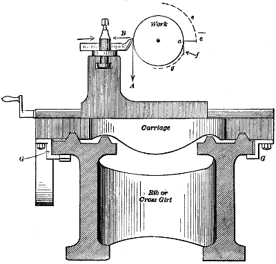
Fig. 621.
In Fig. 621, for example, is a section of a lathe shear, with a slide rest shown in place, and it will be observed that the wear of the V upon the lathe bed, and of the V-groove in the slide rest, will cause the rest to fall in the direction of arrow a, and that a given amount of motion in that direction will have less effect in altering the diameter than it would in any other direction. This is shown on the right hand of the figure as follows: Suppose the cutting point of the tool is at a, and the work will be of the diameter shown by the full circle in the figure. If we suppose the tool point to drop down to f, the work would be turned to the diameter denoted by dotted arc g, while if the tool were moved outwards from a to c the work would be turned to the diameter e. Now since f and c are equidistant from the point a, therefore the difference in the diameters of e and g represents the difference of effect between the wear letting the rest merely fall, or moving it outwards, and it follows that, as already stated, the diameter of the work is less affected by a given amount of wear, when this wear is in the direction of a, than when it is in the direction of b. When the carriage is held down by a weight as is shown in Figs. 577 and 578, there is therefore no lost motion or play in the carriage, which therefore moves steadily upon the shears, unless the pressure of the cut is sufficient in amount, and also in a direction to lift the carriage (as it is in the case of boring with boring tools); but to enable the carriage to remain firm upon the shears under all conditions, it is necessary to provide means to hold it down upon the Vs, which is done by means of gibs g, g, which are secured to the carriage, and fit against the bottom of the bed flange as shown.
Now since lathes are generally used much more frequently on short than on long work, therefore the carriage traverses one part of the shears more than another, and the Vs wear more at the part most traversed, and it follows that if gibs g are set to slide properly at some parts they will not be properly set at another or other parts of the length of the shears; hence the carriage will in some parts have liberty to move from the bed, there being nothing but the weight of the carriage, &c., to hold it down to the Vs. Now, the wear in the direction of a acts directly to cause this inequality of gib fit, whereas that in the direction of b does so to a less extent, as will appear hereafter.
Meantime it may be noted that when the carriage is held down by a suspended weight the shears cannot be provided with cross girts, and are therefore less rigid and more subject to torsion under the strain of the cut; furthermore the amount of the weight must be sufficient to hold the carriage down under the maximum of cut, and this weight acts continuously to wear the Vs, whether the carriage is under cutting duty or not, but the advantage of keeping the carriage firmly down upon the Vs is sufficiently great to cause many to prefer the weighted carriage for light work driven between the lathe centres.
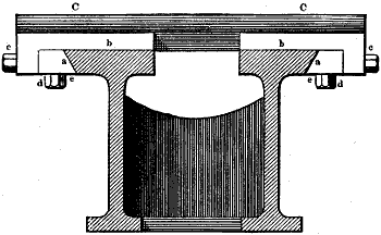
Fig. 622.
Fig. 622 represents the flat shear, the edges being at an angle and the fit of the carriage to the shears being adjusted by the gibs at a a, which are set up by bolts c c and d d. In this case there is a large amount of wearing surface at b b, to prevent the fall of the carriage c, but the amount of end motion (in the direction of b, Fig. 621), permitted to the carriage by reason of the wear of the gibs and shear edges, is greater than the amount of the wear because of the edges being at an angle. It is true that the amount of fall of the carriage on the raised V is also (on account of the angle of the V) greater than the actual amount of the wear, but the effect upon the work diameter is in this case much greater, as will be readily understood from what has already been said. The wearing surface of the raised V may obviously be increased by providing broader Vs, or two Vs instead of having four. This would tend to keep the lathe in line, because the wear due to moving the tailblock would act upon those parts of the shear length that are less acted upon by the carriage, and since the front journal and bearing of the live spindle wear the most, the alignment of the lathe centres would be more nearly preserved.
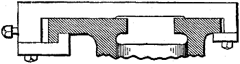
Fig. 623.
Fig. 623 represents another form of parallel edged shears in which the fit of the carriage to the shears is effected at the front end only, the other or back edge being clear of contact with the carriage, but provided with a gib to prevent the carriage from lifting. This allows for any difference in expansion and contraction between the carriage and the shears, while maintaining the fit of the carriage to the bed.
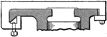
Fig. 624.
A modification of this form (both these forms being taken from “Mechanics”) is shown in Fig. 624, in which the underneath side of the front edge is beveled so that but one row of screws is required to effect the adjustment.
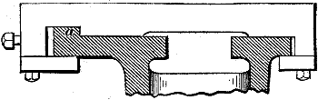
Fig. 625.
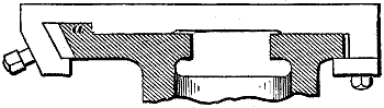
Fig. 626.
Fig. 625 represents a form of bed in which the fit adjustment is also made at the front end only of the bed, and there is a flange or slip at a, which receives the thrust outwards of the carriage; and a similar design, but with a bevelled edge, is shown in Fig. 626.
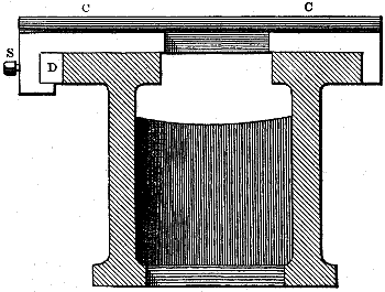
Fig. 627.
In Fig. 627 is shown a lathe shear with parallel edges, the fit being adjusted by a single gib d, set up by set-screws s. In this case the carriage will fall or move endwise, to an amount equal to whatever the amount of the wear may be, and no more, but it may be observed that in all the forms that admit of wear endways (that is to say in the direction of b in Fig. 621), the straightness of the shears is impaired in proportion as its edges are more worn at one part than at another.
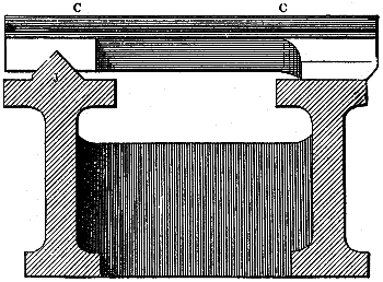
Fig. 628.
A compromise between the flat and the raised V-shear is shown in Fig. 628, there being a V-guide on one side only, as at j. When the carriage is moved by mechanism on the front side of the lathe, and close to the V, this plan may be used, but if the feed screw or other mechanism for traversing the carriage is within the two shears, the carriage should be guided at each end, or if the operating mechanism is at the back of the lathe, the carriage should be guided at the back end, if not at both ends.
In flat shear lathes the tailstock is fitted between the inside edges of the two shears, and the alignment of the tailstock depends upon maintaining a proper fit notwithstanding the wear that will naturally take place in time. The inside edges of the shears are sometimes tapered; this taper makes it much easier to obtain a correct fit of the tailstock to the shears, but at the same time more hard to move the tailstock along the bed. To remedy this difficulty, rollers are sometimes mounted upon eccentrics having journal bearing in the tailstock, so that by operating these eccentrics one half a turn, the rollers will be brought down upon the upper face of the shears, lifting the tailstock and enabling it to be easily moved along the bed to its required position.
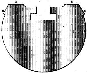
Fig. 629.
In many of the watchmakers’ lathes the outer edges are beveled off as in Fig. 629, the bearing surfaces being on the faces b as well as on the edges a. As a result, edges a are relieved of weight, and therefore to some extent of wear also, and whatever wear faces b have helps the fit at a a.
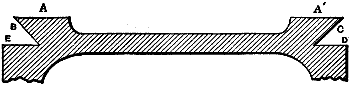
Fig. 630.
In the Barnes lathe, as in several other forms in which the lathe is made (as, for example, in screw-making lathes) the form of bed in Fig. 630 is employed. The tailblock may rest on the surfaces a, a′, b, c, d, and e, or as in the Barnes lathe the tailstock may fit to angles a b, but not to e d, while the carriage fits to b e, and c d, but not to a, the intention being to equalize the wear as much as possible.
The shears of lathes require to be as rigid as possible, because the pressure of the cut, as well as the weight of the carriage, slide rest, and tailstock, and of the work, tends to bend and twist them.
The pressure of the dead centre against the end of the work considered individually, is in a direction to bend the lathe shears upward, but the weight of the work itself acts in an opposite direction.
The strain due to the cut falls in a direction variable with the shape of the cutting tool, but mainly in a direction towards the operator, and, therefore, tending to twist the shears. To resist these strains, lathe shears are usually given the I form shown in the cuts.
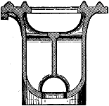
Fig. 631.
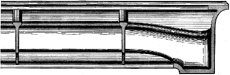
Fig. 632.
Figs. 631 and 632 represent the ribbing in the Putnam Tool Company’s lathe; a middle rib running the entire length, which greatly stiffens it.
The legs supporting lathe shears are, in lathes of ordinary length, placed at each end of the bed, so that the weight of the two heads, that of the work, and that of the carriage and slide rest, as well as the downward pressure of the cut, act combined to cause it to deflect or bend. It is necessary, therefore, in long beds to provide intermediate resting or supporting points to prevent this deflection.
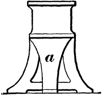
Fig. 633.
Professor Sweet has pointed out that a lathe shears will be more truly supported on three than on four resting points, if the foundation on which the legs rest do not remain permanently level, and in lathes designed by him has given the right-hand end of the shears a single supporting point, as shown at a in Fig. 633.
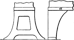
Fig. 634.
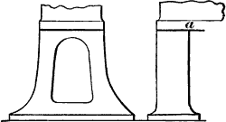
Fig. 635.
J. Richards in an article in “Engineering,” has pointed out also that, when the lathe legs rest upon a floor that is liable from moving loads upon it to move its level, it is preferable that the legs be shaped as in Fig. 634, being narrowest at the foot, whereas when upon a permanent foundation, in which the foundation is intended to impart rigidity to the legs, they should be broader at the base, as in Fig. 635.
The rack on a lathe bed should be a cut one, and not simply a cast one, because when a cutting tool is running up to a corner as against a radial face, the self-acting motion must be stopped and the tool fed into the corner by hand. As a very delicate tool movement is required to cut the corner out just square, it should be capable of easy and steady movement, but in the case of cast racks, the rest will, from defects in the rack teeth, move in little jumps, especially if the pitch of the teeth be coarse. On the other hand it is difficult to cast fine pitches of teeth perfectly, hence the racks as well as the gear teeth should be cut gear and of fine pitch.
The tailblock of a lathe should be capable of easy motion for adjustment along the shears, or bed of the lathe, and readily fixable in its adjusted position. The design should be such as to hold the axial line of its spindle true with the axial line of the live spindle. If the lathe bed has raised Vs there are usually provided two special Vs for the tailblock to slide on, the slide rest carriage sliding on two separate ones. In this case the truth of the axial line of the tail spindle depends upon the truth of the Vs.
If the lathe bed is provided with ways having a flat surface, as was shown in Fig. 622, the surfaces of the edges and of the projection are apt in time to wear, permitting an amount of play which gives room for the tailblock to move out of line. To obviate this, various methods are resorted to, an example being given in the Sellers lathe, Fig. 518.
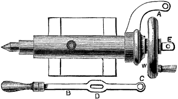
Fig. 636.
In wood turners’ lathes, where tools are often used in place of the dead centre, and in which a good deal of boring is done by such use of the tail spindle, it is not unusual to provide a device for the rapid motion of that spindle. Such a device is shown in Fig. 636; it consists of an arm a to receive the end c of the lever b, c being pivoted to a. The spindle is provided with an eye at e, the wheel w is removed and a pin passed through d and e, so that by operating the handle the spindle can be traversed in and out without any rotary motion of the screw.
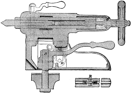
Fig. 637.
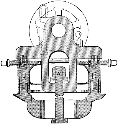
Fig. 638.
When the tailblock of a lathe fits between the edges of the shears, instead of upon raised Vs, it is sometimes the practice to give them a slight taper fitting accurately a corresponding taper on the edges of the shears. This enables the obtenance of a very good fit between the surfaces, giving an increased area of contact, because the surfaces can be filed on their bearing marks to fit them together; but this taper is apt to cause the tailstock to fit so tightly between the shears as to render it difficult to move it along them, and in any event the friction is apt to cause the fit to be destroyed from the wear. An excellent method of obviating these difficulties is by the employment of rollers, such as shown at r in Figs. 637 and 638, which represent the tailstock of the Putnam Tool Company’s lathe. In some cases such rollers are carried on eccentric shafts so that they may be operated to lift the tailstock from the bed when moving it.
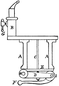
Fig. 639.
A very ready method of securing or releasing a small tailstock to a lathe shears is shown applied to a wood turner’s hand rest in Fig. 639, in which a a represents the lathe shears, b the hand rest, c the fastening bolt, d a piece hinged at each end and having through its centre a hole to receive the fastening bolt, and a counter-sink or recess to receive the nut and prevent it unscrewing. e represents a hinged plate, and f a lever, having a cam at its pivoted end. A slot for the fastening bolt to pass through is provided in the plate e. In this arrangement a very moderate amount of force applied to bring up the cam lever will cause the plate d to be pressed down, carrying with it the nut, and binding the tailstock or the tool rest, as the case may be, with sufficient force for a small lathe.
When a piece of work is driven between the lathe centres, the weight of the work tends to deflect or bend down the tail spindle. The pressure of the cut has also to be resisted by the tail spindle, but this pressure is variable in direction, according to the shape of the tool and the direction of the feed; usually it is laterally towards the operator and upwards. In any event, however, the spindle requires locking in its adjusted position, so as to keep it steady. The pressure on the conical point of the dead centre is in a direction to cause the tail screw to unwind, unless it be a left-hand thread, as is sometimes the case.
If the spindle and the bore in which it operates have worn, the resulting looseness affords facility for the spindle to move in the bore as the pressure of the cut varies, especially when the spindle is far out from the tailstock.
Now, in locking the tail spindle to obviate these difficulties, it is desirable that the locking device shall hold that spindle axially true with the live spindle of the lathe, notwithstanding any wear that may have taken place. The spindle is released from the pressure of the locking device whenever it is adjusted to the work, whether the cut be proceeding or not. Hence, the wear takes place on the bottom of the spindle and of the hole, wear only ensuing on the top of the spindle and bore when the spindle is operated under a slight locking pressure, while the cut is proceeding in order to take up the looseness that may have arisen from wear in the work centres.
In all cases the feed of the cut should be stopped while the centre is adjusted, so as to relieve the spindle and bore from undue wear; but most workmen pay little heed to this; hence the wear ensues, being, as already stated, mainly at the bottom. It is obvious, then, that, if the spindle is to be locked to the side of the bore on which it slides, it will be held most truly in line if it be locked to that side which has suffered least from wear, and this has been shown to be at the top.
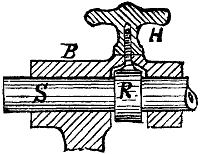
Fig. 640.
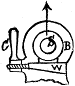
Fig. 641.
The methods usually employed to effect this locking are as follows:—In Fig. 640, s is the tail spindle, b part of the tailblock in section, r a ring-bolt, and h a handled nut. Screwing up the nut h causes r to clamp s to the upper part of the bore of b; while releasing h leaves s free to slide. There are three objections to this plan. The ring r tends to spring or bend s. The weight of r tends to produce wear upon the top of the spindle, and the spindle is not gripped so near to its dead centre end as it might be. If s is a close fit in b the pressure of r could not spring or bend s; but, so soon as wear has taken place, s becomes simply suspended at r, having the pressure of r, and the weight of the work tending to bend it. Another locking device is shown in Fig. 641. It consists of a shoe placed beneath s, and a wedge-bolt beneath it, operated by the handled nut c. Here the pressure is again in a direction to lift s, as denoted by the arrow; but when the wedge w is released the shoe falls away from s, hence the locking device produces no wear upon s. This device may be placed nearer to the end of b, since the wedge may pass through the front leg of the tailstock instead of to the right of it, as in Fig. 640. But s is still suspended from the point of contact of the shoe, and the weight of the work still bends it as much as its play in b will permit.
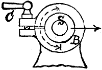
Fig. 642.
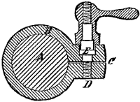
Fig. 643.
Another clamping device is shown in Fig. 642. In this the cylindrical part b of the tailblock is split on one side, and is provided with two lugs. A handled screw passes through the upper lug, and is threaded into the lower one, so that by operating the handle c, the bore may be closed, so as to grip s, or opened to relieve it. This possesses the advantages: First, that it will cause s to be gripped most firmly at the end of b, and give a longer length of bearing of b upon s; and, secondly, that it will grip s top and bottom, and, therefore, prevent its springing from the weight of the work. But, on the other hand, b will close mainly on the side of the split, as denoted by the dotted half-circle, and therefore tend to throw s somewhat in the direction of the arrow, which it will do to an amount answerable to the amount of looseness of s in b. In the Pratt and Whitney lathes this device is somewhat modified, as is shown in Fig. 643. A stud e screws into the lower lug d, having a collar at e let into the upper lug, with a square extending above the upper lug so that the stud may be screwed into d, exerting sufficient pressure to close the bore of b to a neat working fit to the spindle. The handled nut, when screwed up, causes b to grip the spindle firmly; but when released, leaves the spindle a neat working fit and not loose to the amount of the play; hence, the locking device may be released, and the centre adjusted to take up the wear in the work centres while the cut is proceeding, without any movement of the spindle in b, because there is no play between the spindle and b.
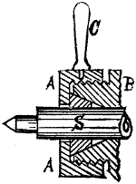
Fig. 644.
In the design shown in Fig. 644, the end b of the tailblock is threaded and is provided with a handled cap nut a a. In the end of the tailblock where the spindle emerges, is provided a cone, and into this cone fits a wedge-shaped ring, as shown. This ring is split quite through on one side, while there are two other slots nearly but not quite splitting the wedge-ring. When the handle c is pulled towards the operator it screws a up on the end b, and forces the wedge-ring up in the conical bore in b. From the split the ring closes upon the spindle s, and grips it. Now, as the ring is weakened by slots in two places besides the split, it closes more nearly cylindrically true than if it had only a split, there being three points where the ring can spring when closing upon s; and from the cone being axially true with the live spindle of the lathe, s is held axially true, notwithstanding any wear of the spindle, because the locking device, being at the extreme end of b, is as near to the dead centre as it is possible to get it; and, furthermore, when c is operated for the release, the wedge-ring opens clear of s, so that s does not touch it when moved laterally. The wear of the bore of b has, therefore, no effect to throw s out of line, nor has the gripping device any tendency to bend or spring s, while the latter is held as close to the work as possible; hence the weight of the work has less influence in bending it. The pitch of the thread and the degree of cone are so proportioned that less than one-quarter rotation of a will suffice to grip or release s, the handle c being so placed on a as to be about vertical when the split ring binds s; hence c is always in a convenient position for the hand to grasp.
In this case, however, the spindle being locked at the extreme end of the hole, there is more liability of the other end moving from the pressure of the cut, or from the weight of the work; hence it would seem desirable that a tail spindle should be locked in two places; one at the dead centre end of the hole, and the other as near the actuating wheel, or handle, as possible, and also that each device should either hold it central to the original bore, notwithstanding the wear, an end that is attained in the Sellers lathes already described.
Slide rests for self-acting or engine lathes are divided into seven kinds, termed respectively as follows: simple, or single, elevating, weighted, gibbed, compound, duplex, and duplex compound. A simple, or single, slide rest contains a carriage and one cross slide, as in Fig. 621. An elevating slide rest is one capable of elevation at one end to adjust the cutting tool height, as in Fig. 499. A weighted slide rest is one held to the shears by a weight, as in Fig. 577. A gibbed slide rest is held to the shears by gibs, as in Fig. 621. A compound slide rest has above the cross slide, a second slide carrying the tool holder, this second slide pivoting to stand at any required angle, as in Fig. 505. A duplex slide rest has two rests on the same cross slide, and in a compound duplex both these two rests are compound, as in Fig. 511. The rest shown on the Putnam lathe in Figs. 492 and 499, is thus an elevating gibbed single rest.
Testing a Lathe.—To test a lathe to find if its live and dead spindles are axially in line one with the other and with the guides on the lathe bed, the following methods may be employed in addition to those referred to under the heading of Erecting.
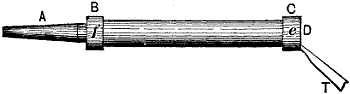
Fig. 645.
To test if the live spindle is true with the bed or shear guides, a piece such as in Fig. 645 may be turned up between the lathe centres, the end a fitting into the live spindle in place of the live centre, and the collars b c being turned to an equal diameter, and the end face d squared off true. The end a must then be placed in the lathe in place of the live centre, the dead centre being removed from contact with the work; with the lathe at rest a tool point may be set to just touch collar c, and if when the carriage is moved to feed the tool past collar b, the tool draws a line along it of equal depth to that it drew along c, the live head is true; the dead centre may then be moved up to engage the work end d, and the lathe must be revolved so that (the tool not having been moved at all by the cross-feed screw) the tool may be traversed back to draw another line along c, and if all three lines are of equal depth the lathe is true. The tool should be fine pointed and set so as to mark as fine a line as possible.
Any View. Side View. Side View. Top View.
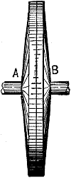
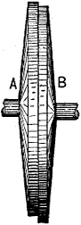
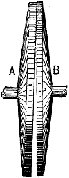
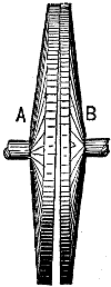
Fig. 646. Fig. 647. Fig. 648. Fig. 649.
Another method is to turn up two discs, such as in Fig. 646, their stems a and b fitting in place of the live and dead centres. One of these discs is put in the place of the live, and the other in that of the dead centre, and if then the lathe tailstock be set up so that the face of b meets that of a, their coincidence will denote the truth of the live and dead spindles. The faces of the discs may be recessed to save work and to meet at their edges only, but their diameters must be equal. If the discs come one higher than the other, as in Fig. 647, the centres are of unequal height. If the faces meet at the top and are open at the bottom, as in Fig. 648, it shows that the back bearing of the live spindle is too high, or that the tail spindle is too low at the dead centre end. If the discs, when viewed from above, come as in Fig. 649, it is proof that either the live spindle or the tail spindle does not stand true with the lathe shears. If the disc faces come so nearly fair that it is difficult to see if they are in contact all around, four pieces of thin paper may be placed equidistant between them, and the grip upon them tested by pulling.
If the tailstock has been set over to turn taper and it is required to set it back to turn parallel again, place a long rod (that has been accurately centred and centre-drilled) between the lathe centres, and turn up one end for a distance of an inch or two.
Then turn it end for end in the lathe and let it run a few moments so that the work centre, running on the dead centre of the lathe, may wear to a proper bed or fit to the lathe centre, and then turn up a similar length at the dead centre end, taking two cuts, the last a fine finishing cut taken with a sharp tool, and feeding the finishing cut from left to right, so that it will be clear of the work end when the cut is finished. Without moving the cross-feed screw of the lathe after the finishing cut is set, take the bar out of the lathe and wind the slide rest carriage, so that the turning tool will stand close to the live centre. Place the bar of iron again in the lathe, with the turned end next to the live centre, and move the lathe carriage, so that the tool is on the turned end of the bar.
Rotate the bar by hand, and if the tool just touches the work without taking a cut the line of centres is parallel with the ways. If there is space between the tool point and the turned end of the bar, the tailstock requires setting over towards the back of the lathe, while if the tool takes a cut the tailstock requires to be set over towards the operator. If a bar is at hand that is known to be true, a pointed tool may be adjusted to just make a mark on the end of the bar when the slide rest is traversed. On the bar being reversed, the tool should leave, when traversed along the bar, a similar mark on the bar.
To test the workmanship of the back head or tailstock, place the forefinger on the spindle close to the hub whence it emerges, and observe how much the hand wheel can be moved without moving the spindle; this will show how much, if any, lost motion there is between the screw and the nut in the spindle. Next wind the back spindle about three quarters of its length out of the tailstock, take hold of the dead centre and pull it back and forth laterally, when an imperfect fit between the spindle and the hole in which it slides will be shown by the lateral motion of the dead centre. Wind the dead centre in again, and tighten and loosen the spindle clamp, and see if doing so moves the spindle in the socket.
To examine the slide rest, move the screw handles back and forth to find how much they may be moved without giving motion to the slides; this will determine the amount of lost motion between the collars of the screws and between the screws themselves and the nuts in which they operate. To try the fit of the slide rest slides, in the stationary sliding ways or Vs, remove the feed screws and move the slide so that only about one-half inch is in contact with the Vs, then move the slide back and forth laterally to see if there is any play. Move the slide to the other end of the Vs, and make a similar test, adjusting the slide to take up any play at either end. Then clean the bearing surfaces and move the slide back and forth on the Vs, and the marks will show the fit, while the power required to move the slide will show the parallelism of the Vs.
If the lathe carriage have a rack feed, operate it slowly by hand, to ascertain if it can be fed slowly and regularly by hand, which is of great importance. Then put the automatic feed in gear, and operate the feed gear back and forth, to determine how much it can be moved without moving the slide rest. To test the fit of the feed screw to the feed nut, put the latter in gear and operate the rack motion back and forth.
To determine whether the cross slide is at a right angle with the ways or shears, take a fine cut over a radial face, such, for example, as the largest face plate, and test the finished plate with a straight edge. If the face plate runs true and shows true with a straight edge, so that it is unnecessary to take a cut over it, grind a piece of steel a little rounding on its end, and fasten it in the tool post or clamp, with the rounded end next to the face plate. Let the rounded end be about 1⁄4 in. away from the face plate, and then put the feed motion into gear, and, with the steel near the periphery of the face plate, let the carriage feed up until the rounded steel end will just grip a piece of thin paper against the face plate tight enough to cause a slight strain in pulling the paper out, then wind the tool in towards the lathe centre and try the friction of the paper there; if equal, the cross slide is true.
To find the amount of lost motion in the screw feed gear, adjust it ready to feed the saddle, and pull the lathe belt so as to revolve the cone spindle backward, until the slide rest saddle begins to move, then mark a fine line on the lathe bed making the line coincident with the end of the lathe saddle or carriage. Then revolve the cone spindle forward, and note how much the cone spindle rotates before the saddle begins to traverse.
If the lathe has an independent feed motion it may be tested in the same manner as above.
In large lathes this is of great consideration, because the work revolves very slowly, and if there is much lost motion in the feed gear, it may take considerable time after the feed is put in gear before the carriage begins to travel. Suppose, for example, a 14-foot pulley is being turned, and that the tool cuts at 15 feet per minute, it will take nearly three minutes for the work to make a revolution.