Volume 2 — Chapter XXVII.—VICE WORK—(Continued). (continued 2)
Reading edition
The link should be warmed to about 300°, or nearly black hot, and pieces of sheet copper placed between the work and the anvil, and between the blacksmith’s tools and the work, so that the latter may not be bruised by the blows delivered to effect the straightening.
After the process has been performed at each end individually the testing should be repeated, because setting the end f may have impaired the setting of end e, in the alignment to f.
It is obvious that the same setting or aligning process would be required in the case of a large link, where the ends were forged separately and welded to the body after the machine work and fitting had been done to them.
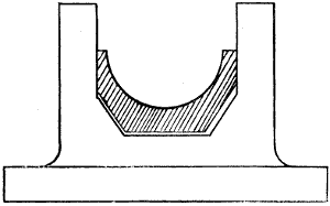
Fig. 2422.
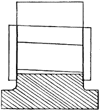
Fig. 2423.
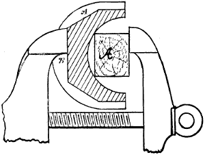
Fig. 2424.
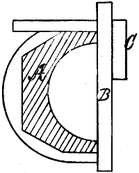
Fig. 2425.
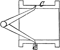
Fig. 2426.
Fitting Brasses to Boxes or to Pillar Blocks.—In the operation of fitting brasses to their boxes or to pillar blocks there are two things to be especially guarded against: First, having the brass let down one-sided, as shown in Fig. 2422; and next, aslant, as shown in Fig. 2423. The first depends on taking the proper amount off the two side faces, and the second in cutting the inside of the flanges fair. To cut the side faces fair, grip the brass in the vice, as shown in Fig. 2424 (the brass being shown in section), in which a is a block of wood. Take the measure of the box, down where the brass will come when home, and, if there be any taper to the box, set the inside calipers to the top of the location for the brass, and after the brass is in the vice place a square under one side-face, as at b in Fig. 2426, and see how much there is to come off. This saves the use of outside calipers, and is better because, not only is the trouble of setting the latter avoided, but the inside calipers can be tried to the box and the work in an instant, and a correction can at once be made if the calipers have got shifted. The cape chisel, or cross-cut, as it is sometimes termed, should first be used, taking a cut close to the flange, and making it half as deep as the calipers (applied as shown in Fig. 2426) show there is metal to come off. Then a similar cut should be taken close to the other flange, especial care being taken to take both cuts equally deep, and leaving as much to come off the other side face of the brass; otherwise, the brass will come atwist. Then take a straight-edge, and, placing its edge fair with the two chisel-grooves, while holding it firmly against the joint face of the brass, mark a line running from one chisel groove to the other; this line serving as a guide for the depth of all the other cape-chisel grooves. Now cut off the intermediate spaces with the flat chisel, using a straight-edge as a guide. If the box is taper, chip the side face to a corresponding taper, using a bevel-square, or estimating the amount by the eye if it is not too much. Now file the chipped surface flat and true, and then turn the brass upside down, gripping it with the wood as before, and dress the other side face (applying the inside calipers as in Fig. 2426), and bring that face down to within about 1⁄64 inch of the size to which the calipers are set. If the block of wood is made a little shorter than the length of the brass, the calipers can be applied without moving the brass from or in the vice. The method of applying the square to these side faces is shown in Fig. 2425, in which a is the brass in section, b a straight-edge, and c a square.
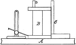
Fig. 2427.
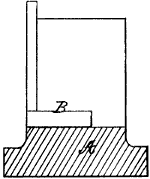
Fig. 2428.
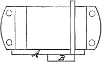
Fig. 2429.
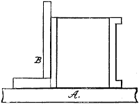
Fig. 2430.
We now turn our attention to the flanges, and apply a square to the crown of the box, bringing the edge of the blade fair with the edge of the box, as shown in Fig. 2428, a representing the box in section, and b the square. Supposing the crown of the box to stand square, as shown in the engraving, and as it should do, we set the brass upon a truly-surfaced iron plate and square up the joint face, as shown in Fig. 2427, in which a is the surfaced iron, b the brass, and c the square. Since, however, the joint face of the brass may not be parallel with the crown face, we may place the square so that its blade edge comes fair with the crown face—that is, as shown at d in Fig. 2427—and set the brass crown (by means of inserting a wooden wedge under its face) truly perpendicular or parallel with the square blade edge. Now try the square with the side face of the brass, setting the latter true with the square blade, as in Fig. 2430; a being the iron plate and b the square; and, supposing the box to be true, as it usually is, we may set a scribing-block, as shown in Fig. 2427, and mark off how much is to come off the flanges by scribing a line around the flange, sufficiently depressing the scriber-point to allow an equal amount to come off each of the flanges. Sometimes, however, the inside faces of the box are not true with the outside face. To test this, we place a straight-edge across the outside face, place a square on it, and apply it to the inside face of the box, as in Fig. 2429, which is a plan view of the box, a being the straight-edge and b the square. If the square thus applied shows a want of truth in the box, we may set the brass over when adjusting it (as in Fig. 2427) to a corresponding amount, and thus mark off the flanges to suit the box.
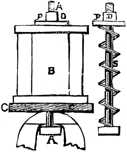
Fig. 2431.
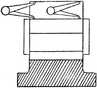
Fig. 2432.
To hold the brass while operating on the flanges, we resort to the device shown in Fig. 2431, in which a is a bolt, b the brass, c a piece of hard wood, and p a clamp fastened down by a nut d. To sustain the plate p, so that it shall not fall down on the piece of wood every time the brass is taken out to try it in the box, we may insert the spiral spring s, shown in the separate view of the bolt, nut, and plate. One such holding device will do for different sizes of brasses, by either gripping the bolt lower down in the vice jaws or putting washers between the nut and the plate. This will hold the brass very firmly, and at the same time leave the whole of the flange easily got at. When the flanges are dressed, we may try the brass in the box, putting red-lead marking on the box to mark where the brass binds. While letting the brass down, however, we must be careful to let it down fair, to avoid the state of things shown in Figs. 2422 and 2423. A ready method of doing this is (supposing the box to be true, as it should be, and making the necessary allowance if it is not), to set a pair of inside calipers to the joint face of the brass and the top of the box, as shown in Fig. 2432, trying the calipers (in the two positions there shown) on both sides of the box. This should be done every time the brass is tried in the box, until such time as the brass begins to bed against the bottom of the box.
We now come to the bedding of the brass to its seat in the box. This requires skillful treatment; for one mistake will involve a great deal of extra work to rectify it.
In fitting the brass to the box care must be taken to leave it a rather tighter fit to the box than it requires to be when finished, that is after the bore has been made, because in the boring operation the sides of the brass are apt to close and loosen the fit of the brass to the box.
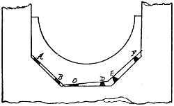
Fig. 2433.
When the side faces and flanges are so far fitted as to render probable the brass driving home at the next trial, the bed of the box should be given a coat of red-lead marking, and small pellets of stiff red lead or putty should be stuck on the bottom of the box, two at each end of each bevel, and two at each end of the bottom, with one in the middle of the bottom and each bevel, as shown at a, b, c, d, e, f, in Fig. 2433, by the black spots. Then when the brass comes home, it will flatten these pellets, and their thickness (when the brass is taken out) will show how much the bevels are out, and how much to take off the brass to make it bed. These pellets must be restored to their original shape every time the brass is tried; otherwise, they may mislead. To insure their sticking to the box, and not coming out with the brass, the bottom of the box must have red-lead marking kept upon it. The chipping should continue until the pellets flatten out equally on the two bevels, but are left a little thicker on the bottom. If this is not done, the bottom will bed first, causing a great deal of extra filing, because filing the side bevels will let the bottom down too far.
In driving the brass in and out of the box while fitting it, a piece of wood must be used to strike on, otherwise the brass will stretch during the fitting and come loose in the box during the boring.[33]
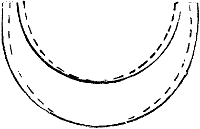
Fig. 2434.
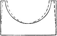
Fig. 2435.
The patterns from which the castings for brasses are moulded should not be made of the same angle or sweep on the bedding part or bottom as the bottom of the box, pedestal, or pillar block, because the brass casting, in cooling in the mould, contracts across the bore; thus if in Figs. 2434 and 2435 the full lines denote the shape of the pattern the dotted lines denote the shape the casting will be.
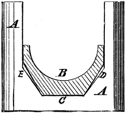
Fig. 2436.
The result of this is that when the brass is let down in the box it will bed on the crown and not at the sides. Thus in Fig. 2436, a is a pedestal, and b a brass which beds at c, but not at d or e. In Fig. 2437 is shown an example of a brass, with a circular bottom, which would bed at the crown c, but not at the sides d e, until the metal was cut down to the dotted circle f.
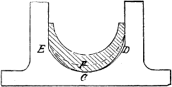
Fig. 2437.
The amount to which this contraction in the mould occurs varies with the size of the brass, the difference in the thickness at the crown and at the face joint, the composition of the metal of which the casting is made, and the temperature of the metal when poured into the mould. It should always be allowed for, however, for the following reasons. Referring again to Fig. 2436, it will be noted that it requires a heavy cut off c to bring e, d to a bearing, while it is apparent that if the brass met the box at e, d before it did at c, but little filing at e, d would let the brass down a long way. It saves work, therefore, to so make the pattern as to insure that the brass casting shall have bedding contact at d and e before it does at c. As an example of the allowance to be made for this purpose, it may be stated that in brasses of 6 inches bore and 9 inches long, the hexagon of the brass pattern at d, e, Fig. 2436, would require about 1⁄16 inch put on them to compensate for the contraction, supposing that the hexagon on the brass pattern were made at first to fit the hexagon of the pedestal or axle box.
To originate a true flat surface we proceed as follows: In the absence of a standard plate to go by, we must have three plates, and one of them must be accepted as a provisional or temporary standard. This we will call No. 1, and we fit Nos. 2 and 3 to it and then try them together, and if they also fit it is proof that No. 1 was true, and that all three are therefore true. It will very rarely happen, however, that this is the case; but Nos. 2 and 3 merely serve to show how much No. 1 was out of true.
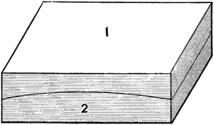
Fig. 2438.
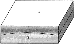
Fig. 2439.
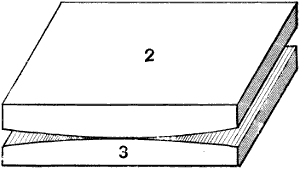
Fig. 2440.
Suppose, for example, that No. 1 is concave in its length, and we fit No. 2 to it, as in Fig. 2438, and then fit No. 3 to it as in Fig. 2439, and when we come to put Nos. 2 and 3 together, as in Fig. 2440, we find that they are out of true to twice the amount that No. 1 is, and that all the work that has been done to them to fit them to No. 1 has been thrown away, and possibly to make them worse instead of better. It becomes important therefore to select the most true plate for No. 1, and this we may do as follows:—
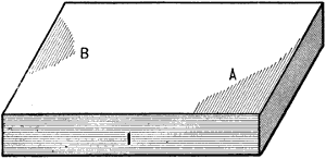
Fig. 2441.
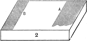
Fig. 2442.
If we have a straight-edge that is known to be true, we may lay it on the face of a plate and move it laterally from each end alternately, and if it swings from the centre the plate face is rounding, while if it shuffles across moving first at one end and then at the other the face is hollow; but if it glides as it were across, the surface is nearer true. The straight-edge must not be pressed to the plate, but merely touched laterally to make it move laterally, for if we take a true straight-edge and press it vertically to a true surface while moving it, it will show the marks of contact the most plainly immediately beneath the parts where it is pressed. Selecting by this means the two plates that appear to be the most true we proceed to test them further as follows: We give to one of them which we will call No. 1 a light coat of red marking, and placing it upon the other or No. 2, we move it about in all directions and then take the two apart to examine the bearing marks. Suppose then that No. 1 shows the bearing marks to be at the shaded places, a and b, in Fig. 2441, while the bearing marks on No. 2 are as at the shaded parts a and b in Fig. 2442, the two ends a having been placed together; then we know that b is a high spot on No. 1, and a a high spot on No. 1 for the following reasons. The marks at a, No. 2, have been made by the marking at a on No. 1, and will extend across No. 2, a distance depending upon how much No. 1 has moved across No. 2, for if corner a of No. 1 had only moved half-way across No. 2, it could only have marked half-way across it. Similarly spot b on No. 1 has marked spot b in No. 2, because it has been moved all the way across, it being evident that the marking on b, No. 1, can only mark plate 2 as far across its width as it is moved across it. From this it follows that the higher or more prominent a spot is the less will be the area of the bearing mark at that spot.
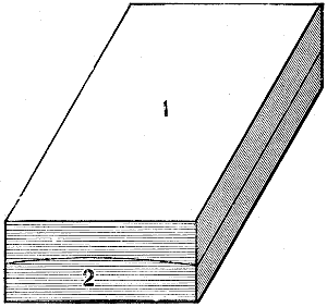
Fig. 2443.
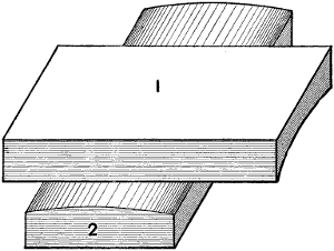
Fig. 2444.
Now suppose that the two plates were curved to an equal degree as in Fig. 2443, and the bearing marks would extend all over both surfaces; but we may discover this error by turning one plate at a right angle, as in Fig. 2444, in which case the bearing marks would show along the edges of No. 1 and along the middle of No. 2, and we may correct each with the file until both plates mark all across and from end to end when tried together lengthways as in Fig. 2443, and one across the other as in Fig. 2444. But the plates may be curved to a different degree, as in Fig. 2445, and it then becomes necessary to know which to file the most in correcting them and fitting them together, which we may discover as follows:—
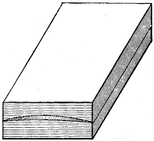
Fig. 2445.
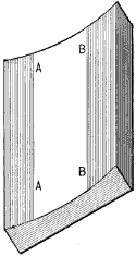
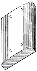
Fig. 2446. Fig. 2447.
We give one plate a light coat of red marking and rub it upon the other both sideways and lengthways. Suppose that on being separated and examined the bearing marks, shown as at a a and b b, Fig. 2446, on one plate, and at c c and d d, Fig. 2447, on the other, and as those at a a and b b are the narrowest, or in other words extend the least distance across the plate, it is proof that this plate is more concave than the other plate is convex, and therefore needs the most correction. This is plain because whatever part of a plate touches another, will, if the two are merely pressed together, only leave a bearing mark equal in area to itself, while this area will obviously be increased in proportion as one plate is moved about upon the other.
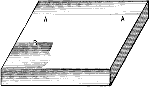
Fig. 2448.
When the object is to merely produce a flat surface, independent of the thickness or parallelism of the plate, it is not always necessary to file or scrape the whole of the area showing bearing marks. Suppose, for example, that the marks appear as in Fig. 2448, and as the bearing marks at a a show that edge of the plate to be straight already, all that is necessary is to ease the surface at b in order to let that side of the plate come up.
When we have fitted two of the three plates together we must accept one of them as a true one and (calling it No. 1) fit Nos. 3 and also 2 to it, and then try Nos. 2 and 3 together. If these require correcting the amount of correction must be made equal on each, and when this is done we must accept one of these two (say No. 3) as the standard, fit No. 1 to it, so that Nos. 1 and 2 both having been fitted to No. 3 may be tried together and both corrected equally; nor will the surfaces of any of them be true until all three will interchange in this manner and show a perfect contact.
It is to be noted, however, that in this process we have not altogether eliminated the error due to the deflection of each plate. Suppose, for example, a plate to be resting on its feet and its middle will sag or deflect to some extent (very minute though it may be in a small plate), and when we place another plate upon it the latter will also sag or deflect if its points of contact are far apart, and in any event the truing is performed by the bearing-marks, which the operator knows show the darkest and the brightest where the contact is greatest; hence by the time the contact marks show equally strong all over, the top plate will have been fitted to suit the deflection of the lower one. Since, however, the nearer the points of contact (between the plates) are together the less the degree of deflection, it is better in trying them to place the test plate on the top of the one being operated on. If the plates are long ones it will not answer to have more than three points of rest for the lower plate, unless the foundation on which the plate rests is made so true that each resting point of the plate will bear with equal pressure on the foundation plate or stone.
To eliminate as far as possible the deflection, the three plates may be got up by the process described, and then finished by trying them when resting on their edges (the trued surfaces standing vertical), interchanging the three plates as before.
In this case the surface will be true when standing vertical as finished, but there will still be some untruth from deflection when the plates are rested on their feet, though it will be less in amount than if the plates were finished on their feet as first described.
In finishing surface plates with a hand scraper, we have a surface that bears in fine spots only, these spots being the tops only of the scraper marks. Now the depth of the scraper marks are unequal, because immediately after the scraper is sharpened it cuts the easiest and the deepest, the scraper cutting less deep as its edge dulls. The operator regulates this to some extent by applying a greater pressure to the scraper as it gets dull, but from differences in the texture of the metal and from other causes it is impracticable to make the scraper cut equally deep at each stroke, as a result the tops of the scraper marks, which are the points of contact of the plates, wear away quickest, and the plate soon loses, to some extent, its truth.
Again, work that is so small as to cover part of the plate surface only, wears the part of the plate to which it is applied, and although the careful workman usually applies small work at and near the outside edges of the plate only, still these are all elements tending to produce increased local wear and to throw the plate out of true.
To obviate this difficulty the surface should be got up to bear all over, thus greatly increasing its bearing area and proportionately decreasing its wear. To produce such a surface the following plan was adopted by the author in 1876.
The filing process was continued with fine Groubet files, and testing the plates, rubbing them together sufficiently to mark them without the use of oil. Very short file strokes must be employed, and great care taken to apply the file to the exact necessary spots and places.
Then instead of using the scraper, No. 0 French emery paper was used, wrapped over the end of a flat file. The plates being interchanged and trued with No. 0, No. 00 was used, and the testing and interchanging repeated. These grades of emery paper were then wrapped or folded over the curved end of a piece of wood, the plates interchanged and rubbed together as before, and the emery paper used as described for the scraper. Subsequently Nos. 000 and 0000 French emery paper were similarly applied until the plates were finished. Much assistance to this method may be rendered by taking a piece of Water of Ayr stone, and truing its surfaces by rubbing them on the plates after the fine filing and before the emery papering. Then while applying the finer grades of emery paper the stone may be rubbed (with oil or water) in various directions over the surface. This has the effect of wearing off the very fine protuberances due to the emery paper cutting the metal most around its pores, and furthermore it causes the marks made in testing to show more plainly.
In skillful hands this process very far surpasses, both in the superiority of its results and in rapidity of execution, the scraping process, leaving a brilliant polished surface, so smooth that it feels as soft as satin, and the contact becomes so complete that no bearing marks can be distinguished.
In this process great care must be taken in cleaning the surfaces before applying them together, as the finest particle of dust will cut scratches, which though imperceptible on scraped surfaces, appear very coarse and deep on these smooth ones.
The amount of metal taken off by the finer grades of emery paper is so small as to be scarcely appreciable, save that it slightly discolors the emery paper.
The finest test for plates finished in this way is to rest the lower one quite level, clean it with alcohol, wipe it clean with old linen rag and finally with the palm of the hand, which if quite dry is more effective than anything else. The eye should carefully sight the plate surface with the light reflecting on that surface, when particles too fine to be felt may be observed and wiped off with the hand. In dry weather it is a difficult matter to clean the plates perfectly, as while one is being cleaned the fine particles of matter floating in the air rest upon the other; but in rainy weather the cleaning is much easier.
The plates being cleaned one must be lowered vertically on the other where it will float, there being a film of air between the two which it is almost impossible to exclude by pressure even though the plates be moved while pressed together.
If under these conditions the surfaces are not true and the top plate be set in motion in various directions, by a light finger touch it will swing round, the parts of the surface most in contact being the centre of motion. Suppose then the top plate to swing from one end it should be turned end for end on the bottom plate, and if the location of the centre of motion is still at the same end of the top plate, that plate is high there, while if the centre of motion in both cases is at the same end of the bottom plate it is the one that contains the error.
If the top plate swings upon its own centre of motion it must be moved farther off the bottom one, first on one side and then on the other, to discover if it or the bottom plate is in error; while if the top plate swings first from one end and then from the other, one or both of the plates are hollow and the top one must again be moved farther off the lower one, and the test by motion continued. The error discoverable in this way is very much finer than can be discovered by the marks of contact, since a plate showing quite even contact when quite dry and clean, and tested as lightly and carefully as may be will show error by this motion test. The error being so small in amount that it may be corrected by rubbing the plate with rag and oil, applied under hand pressure to the plate.
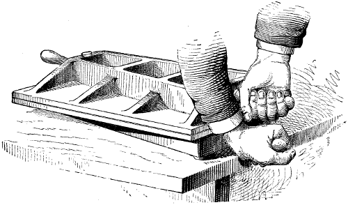
Fig. 2449.
To cause the plates to bind together so that rubbing one on the other will leave contact marks, the top plate must be placed about an inch over the corner of the bottom one, pressed closely to it and forced laterally over it. A pair of plates of the Whitworth pattern (such as shown in Fig. 2449) placed by the author in the Centennial Exhibition, required, when put together dry as above, 3411⁄2 lbs to slide the top one over the other, which was due to the friction caused between the surfaces by the atmospheric pressure acting on the back surface of the plate, the latter having a superficial area of 12 by 8 inches.
Here it may be added that a plate of the same dimensions, and having its surface finished simply by filing with a dead smooth file, which plate was made for exhibition at a lecture on hand work, delivered before the Spring Garden Institute of Philadelphia, required a force of 22 lbs. to slide on the one on which it rested.
If two plates finished by the above method be placed together by sliding one upon the other it will be found that with the hands applied as in Fig. 2449, they can be separated or pulled apart with less force than it requires to slide one upon the other, because the plates bend and unlap, as would be the case if two sheets of paper were wetted and placed together and then taken apart by pulling two edges in opposite directions. But if the power to pull the plates apart be applied at the middle of the plate it will require a much greater force to separate them, although how much is problematical, no experiments having been made upon the subject. Furthermore the friction between two such plates will be greater if the surfaces be lubricated than if quite dry.
Thus, with the surfaces cleaned by alcohol, the top plate will move comparatively easily, but if the surfaces be slightly oiled and then wiped apparently quite clean with old dry rags, the friction will be a maximum. If then a piece of rag, say of an area of an inch, have one drop of oil upon it and be then applied to the surfaces of two plates after they have been cleaned with alcohol, the friction will still be about 3 lbs. per inch of area of one plate. With the surfaces well lubricated it will still require more power to slide one plate upon the other than would be the case were both plates quite dry.
The reason of this is that when quite dry it is impracticable to exclude the air from between the surfaces, whereas with the lubrication the air is more perfectly excluded and the atmospheric pressure forces the plates together.