Volume 1 — Chapter III.—THE TEETH OF GEAR-WHEELS (continued). (continued 3)
Reading edition
TABLE FOR DETERMINING THE RELATION BETWEEN PITCH DIAMETER, PITCH, AND NUMBER OF TEETH IN GEAR-WHEELS.
Pitch. Number of Teeth.
1. 2. 3. 4. 5. 6. 7. 8. 9.
1 .3183 .6366 .9549 1.2732 1.5915 1.9099 2.2282 2.5465 2.8648
1 1⁄8 .3581 .7162 1.0743 1.4324 1.7905 2.1486 2.5067 2.8648 3.2229
1 1⁄4 .3979 .7958 1.1937 1.5915 1.9894 2.3873 2.7852 3.1831 3.5810
1 3⁄8 .4377 .8753 1.3130 1.7507 2.1884 2.6260 3.0637 3.5014 3.9391
1 1⁄2 .4775 .9549 1.4324 1.9099 2.3873 2.8648 3.3422 3.8197 4.2971
1 5⁄8 .5173 1.0345 1.5517 2.0690 2.5862 3.1035 3.6207 4.1380 4.6552
1 3⁄4 .5570 1.1141 1.6711 2.2282 2.7852 3.3422 3.8993 4.4563 5.0134
1 7⁄8 .5968 1.1937 1.7905 2.3873 2.9841 3.5810 4.1778 4.7746 5.3714
2 .6366 1.2732 1.9099 2.5465 3.1831 3.8197 4.4563 5.0929 5.7296
2 1⁄8 .6764 1.3528 2.0292 2.7056 3.3820 4.0584 4.7348 5.4112 6.0877
2 1⁄4 .7162 1.4324 2.1486 2.8648 3.5810 4.2972 5.0134 5.7296 6.4457
2 3⁄8 .7560 1.5120 2.2679 3.0239 3.7799 4.5359 5.2919 6.0479 6.8038
2 1⁄2 .7958 1.5915 2.3873 3.1831 3.9789 4.7746 5.5704 6.3662 7.1619
2 5⁄8 .8355 1.6711 2.5067 3.3422 4.1778 5.0133 5.8499 6.6845 7.5200
2 3⁄4 .8753 1.7507 2.6260 3.5014 4.3767 5.2521 6.1274 7.0028 7.8781
2 7⁄8 .9151 1.8303 2.7454 3.6605 4.5757 5.4908 6.4059 7.3211 8.2362
3 .9549 1.9099 2.8648 3.8197 4.7746 5.7296 6.6845 7.6394 8.5943
3 1⁄4 1.0345 2.0690 3.1035 4.1380 5.1725 6.2070 7.2415 8.2760 9.3105
3 1⁄2 1.1141 2.2282 3.3422 4.4563 5.5704 6.6845 7.7986 8.9126 10.0268
3 3⁄4 1.1937 2.3873 3.5810 4.7746 5.9683 7.1619 8.3556 9.5493 10.7429
4 1.2732 2.5465 3.8197 5.0929 6.3662 7.6394 8.9127 10.1839 11.4591
4 1⁄2 1.4324 2.8648 4.2972 5.7296 7.1619 8.5943 10.0267 11.4591 12.8915
5 1.5915 3.1831 4.7746 6.3662 7.9577 9.5493 11.1408 12.7324 14.3240
5 1⁄2 1.7507 3.5014 5.2521 7.0028 8.7535 10.5042 12.2549 14.0056 15.7563
6 1.9099 3.8196 5.7295 7.6394 9.5493 11.4591 13.3690 15.2788 17.1887
The following rules and examples show how the table is used:
Rule 1.—Given —— number of teeth and pitch; to find —— pitch diameter.
Select from table in columns opposite the given pitch—
First, the value corresponding to the number of units in the number of teeth.
Second, the value corresponding to the number of tens, and multiply this by 10.
Third, the value corresponding to the number of hundreds, and multiply this by 100. Add these together, and their sum is the pitch diameter required.
Example.—What is the pitch diameter of a wheel with 128 teeth, 11⁄2 inches pitch?
We find in line corresponding to 11⁄2 inch pitch—
Pitch diameter for 8 teeth 3.81 97
„ „ 20 „ 9.54 9
„ „ 100 „ 47.75
„ „ 128 „ 61.11 87
Or about 611⁄8′′. Answer.
Rule 2.—Given —— pitch diameter and number of teeth; to find —— pitch.
First, ascertain by Rule 1 the pitch diameter for a wheel of 1-inch pitch, and the given number of teeth.
Second, divide given pitch diameter by the pitch diameter for 1-inch pitch.
The quotient is the pitch desired.
Example.—What is the pitch of a wheel with 148 teeth, the pitch diameter being 72′′?
First, pitch diameter for 148 teeth, 1-inch pitch, is—
8 teeth 2.54 65
40 „ 12.73 2
100 „ 31.83
148 „ 47.10 85
Second, 72 = 1.53 inch equal to the pitch.
47.1
This is nearly 11⁄2-inch pitch, and if possible the diameter would be reduced or the number of teeth increased so as to make the wheel exactly 11⁄2-inch pitch.
Rule 3.—Given —— pitch and pitch diameter; to find —— number of teeth.
First, ascertain from table the pitch diameter for 1 tooth of the given pitch.
Second, divide the given pitch diameter by the value found in table.
The quotient is the number required.
Example.—What is the number of teeth in a wheel whose pitch diameter is 42 inches, and pitch is 21⁄2 inches?
First, the pitch diameter, 1 tooth, 21⁄2-inch pitch, is 0.7958 inches.
Second. 42 = 52.8. Answer.
0.7958
This gives a fractional number of teeth, which is impossible; so the pitch diameter will have to be increased to correspond to 53 teeth, or the pitch changed so as to have the number of teeth come an even number.
Whenever two parallel shafts are connected together by gearing, the distance between centres being a fixed quantity, and the speeds of the shafts being of a fixed ratio, then the pitch is generally the best proportion to be changed, and necessarily may not be of standard size. Suppose there are two shafts situated in this manner, so that the distance between their centres is 84 inches, and the speed of one is 21⁄2 times that of the other, what size wheels shall be used? In this case the pitch diameter and number of teeth of the wheel on the slow-running shaft have to be 21⁄2 times those of the wheel on the fast-running shaft; so that 84 inches must be divided into two parts, one of which is 21⁄2 times the other, and these quantities will be the pitch radii of the wheels; that is, 84 inches are to be divided into 31⁄2 equal parts, 1 of which is the radius of one wheel, and 21⁄2 of which the radius of the other, thus 84′′/31⁄2 = 24 inches. So that 24 inches is the pitch radius of pinion, pitch diameter = 48 inches; and 21⁄2 × 24 inches = 60 inches is the pitch radius of the wheel, pitch diameter = 120 inches. The pitch used depends upon the power to be transmitted; suppose that 25⁄8 inches had been decided as about the pitch to be used, it is found by Rule 3 that the number of teeth are respectively 143.6, and 57.4 for wheel and pinion. As this is impossible, some whole number of teeth, nearest these in value, have to be taken, one of which is 21⁄2 times the other; thus 145 and 58 are the nearest, and the pitch for these values is found by Rule 2 to be 2.6 inches, being the best that can be done under the circumstances.
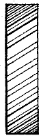
Fig. 183.
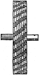
Fig. 184.
The forms of spur-gearing having their teeth at an angle to the axis, or formed in advancing steps shown in Figs. 183 and 184, were designed by Dr. Hooke, and “were intended,” says the inventor, “first to make a piece of wheel work so that both the wheel and pinion, though of never so small a size, shall have as great a number of teeth as shall be desired, and yet neither weaken the wheels nor make the teeth so small as not to be practicable by any ordinary workman. Next that the motion shall be so equally communicated from the wheel to the pinion that the work being well made there can be no inequality of force or motion communicated.
“Thirdly, that the point of touching and bearing shall be always in the line that joins the two centres together.
“Fourthly, that it shall have no manner of rubbing, nor be more difficult to make than common wheel work.”
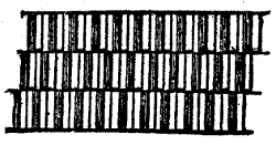
Fig. 185.
The objections to this form of wheel lies in the difficulty of making the pattern and of moulding it in the foundry, and as a result it is rarely employed at the present day. For racks, however, two or more separate racks are cast and bolted together to form the full width of rack as shown in Fig. 185. This arrangement permits of the adjustment of the width of step so as to take up the lost motion due to the wear of the tooth curves.
Another objection to the sloping of the teeth, as in Fig. 183, is that it induces an end pressure tending to force the wheels apart laterally, and this causes end wear on the journals and bearings.
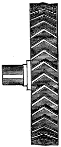
Fig. 186.
To obviate this difficulty the form of gear shown in Fig. 186 is employed, the angles of the teeth from each side of the wheel to its centre being made equal so as to equalize the lateral pressure. It is obvious that the stepped gear, Fig. 184, is simply equivalent to a number of thin wheels bolted together to form a thick one, but possessing the advantage that with a sufficient number of steps, as in the figure, there is always contact on the line of centres, and that the condition of constant contact at the line of centres will be approached in proportion to the number of steps in the wheel, providing that the steps progress in one continuous direction across the wheel as in Fig. 184. The action of the wheels will, in this event, be smoother, because there will be less pressure tending to force the wheels apart.
But in the form of gearing shown in Fig. 183, the contact of the teeth will bear every instant at a single point, which, as the wheels revolve, will pass from one end to the other of the tooth, a fresh contact always beginning on the first side immediately before the preceding contact has ceased on the opposite side. The contact, moreover, being always in the plane of the centres of the pair, the action is reduced to that of rolling, and as there is no sliding motion there is consequently no rubbing friction between the teeth.
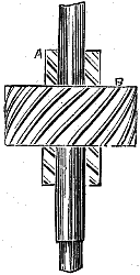
Fig. 187.
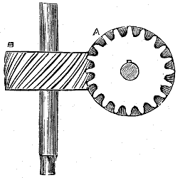
Fig. 188.
A further modification of Dr. Hooke’s gearing has been somewhat extensively adopted, especially in cotton-spinning machines. This consists, when the direction of the motion is simply to be changed to an angle of 90°, in forming the teeth upon the periphery of the pair at an angle of 45° to the respective axes of the wheels, as in Figs. 187 and 188; it will then be perceived that if the sloped teeth be presented to each other in such a way as to have exactly the same horizontal angle, the wheels will gear together, and motion being communicated to one axis the same will be transmitted to the other at a right angle to it, as in a common bevel pair. Thus if the wheel a upon a horizontal shaft have the teeth formed upon its circumference at an angle of 45° to the plane of its axis it can gear with a similar wheel b upon a vertical axis. Let it be upon the driving shaft and the motion will be changed in direction as if a and b were a pair of bevel-wheels of the ordinary kind, and, as with bevels generally, the direction of motion will be changed through an equal angle to the sum of the angles which the teeth of the wheels of the pair form with their respective axes. The objection in respect of lateral or end pressure, however, applies to this form equally with that shown in Fig. 183, but in the case of a vertical shaft the end pressure may be (by sloping the teeth in the necessary direction) made to tend to lift the shaft and not force it down into the step bearing. This would act to keep the wheels in close contact by reason of the weight of the vertical shaft and at the same time reduce the friction between the end of that shaft and its step bearing. This renders this form of gearing preferable to skew bevels when employed upon vertical shafts.
It is obvious that gears, such as shown in Figs. 187 and 188 may be turned up in the lathe, because the teeth are simply portions of spirals wound about the circumference of the wheel. For a pair of wheels of equal diameter a cylindrical piece equal in length to the required breadth of the two wheels is turned up in the lathe, and the teeth may be cut in the same manner as cutting a thread in the lathe, that is to say, by traversing the tool the requisite distance per lathe revolution. In pitches above about 1⁄4 inch, it will be necessary to shape one side of the tooth at a time on account of the broadness of the cutting edges. After the spiral (for the teeth are really spirals) is finished the piece may be cut in two in the lathe and each half will form a wheel.
To find the full diameter to which to turn a cylinder for a pair of these wheels we proceed as in the following example: Required to cut a spiral wheel 5 inches in diameter and to have 30 teeth. First find the diametral pitch, thus 30 (number of teeth) ÷ 5 (diameter of wheel at pitch circle) = 6; thus there are 6 teeth or 6 parts to every inch of the wheel’s diameter at the pitch circle; adding 2 of these parts to the diameter of the wheel, at the pitch circle we have 5 and 2⁄6 of another inch, or 52⁄6 inches, which is the full diameter of the wheel, or the diameter of the addendum, as it is termed.
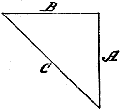
Fig. 189.
It is now necessary to find what change wheels to put on the lathe to cut the teeth out the proper angle. Suppose then the axes of the shafts are at a right angle one to the other, and that the teeth therefore require to be at an angle of 45° to the axes of the respective wheels, then we have the following considerations. In Fig. 189 let the line a represent the circumference of the wheel, and b a line of equal length but at a right angle to it, then the line c, joining a, b, is at an angle of 45°. It is obvious then that if the traverse of the lathe tool be equal at each lathe revolution to the circumference of the wheel at the pitch circle, the angle of the teeth will be 45° to the axis of the wheel.
Hence, the change wheels on the lathe must be such as will traverse the tool a distance equal to the circumference at pitch circle of the wheel, and the wheels may be found as for ordinary screw cutting.
If, however, the axes of the shafts are at any other angle we may find the distance the lathe tool must travel per lathe revolution to give teeth of the required angle (or in other words the pitch of the spiral) by direct proportion, thus: Let it be required to find the angle or pitch for wheels to connect shafts at an angle of 25°, the wheels to have 20 teeth, and to be of 10 diametral pitch.
Here, 20 ÷ 10 = 2 = diameter of wheel at the pitch circle. The circumference of 2 inches being 6.28 inches we have, as the degrees of angle of the axes of the shafts are to 45°, so is 6.28 inches (the circumference of the wheels, to the pitch sought).
Here, 6.28 inches × 45° ÷ 25° = 11.3 inches, which is the required pitch for the spiral.
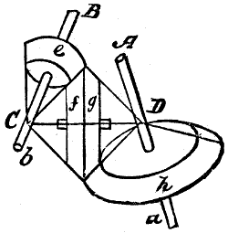
Fig. 190.
When the axes of the shafts are neither parallel nor meeting, motion from one shaft to another may be transmitted by means of a double gear. Thus (taking rolling cones of the diameters of the respective pitch circles as representing the wheels) in Fig. 190, let a be the shaft of gear h, and b b that of wheel e. Then a double gear-wheel having teeth on f, g may be placed as shown, and the face f will gear with e, while face g will gear with h, the cone surfaces meeting in a point as at c and d respectively, hence the velocity will be equal.
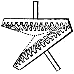
Fig. 191.
When the axial line of the shafts for two gear-wheels are nearly in line one with the other, motion may be transmitted by gearing the wheels as in Fig. 191. This is a very strong method of gearing, because there are a large number of teeth in contact, hence the strain is distributed by a larger number of teeth and the wear is diminished.
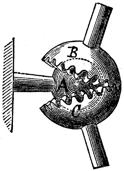
Fig. 192.
Fig. 192 (from Willis’s “Principles of Mechanism”) is another method of constructing the same combination, which admits of a steady support for the shafts at their point of intersection, a being a spherical bearing, and b, c being cupped to fit to a.
Rotary motion variable at different parts of a rotation may be obtained by means of gear-wheels varied in form from the true circle.
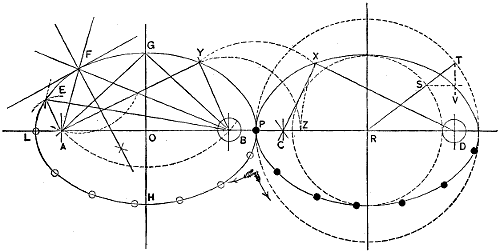
Fig. 193.
The commonest form of gearing for this purpose is elliptical gearing, the principles governing the construction of which are thus given by Professor McCord. “It is as well to begin at the foundation by defining the ellipse as a closed plane-curve, generated by the motion of a point subject to the condition that the sum of its distances from two fixed points within shall be constant: Thus, in Fig. 193, a and b are the two fixed points, called the foci; l, e, f, g, p are points in the curve; and a f + f b = a e + e b. Also, a l + l b = a p + p b = a g + g b. From this it follows that a g = l o, o being the centre of the curve, and g the extremity of the minor axis, whence the foci may be found if the axes be assumed, or, if the foci and one axis be given, the other axis may be determined. It is also apparent that if about either focus, as b, we describe an arc with a radius greater than b p and less than b l, for instance b e, and about a another arc with radius a e = l p-b e, the intersection, e, of these arcs will be on the ellipse; and in this manner any desired number of points may be found, and the curve drawn by the aid of sweeps.
“Having completed this ellipse, prolong its major axis, and draw a similar and equal one, with its foci, c, d, upon that prolongation, and tangent to the first one at p; then b d = l p. About b describe an arc with any radius, cutting the first ellipse at y and the line l at z; about d describe an arc with radius d z, cutting the second ellipse in x; draw a y, b y, c x, and d x. Then a y = d x, and b y = c x, and because the ellipses are alike, the arcs p y and p x are equal. If then b and d are taken as fixed centres, and the ellipses turn about them as shown by the arrows, x and y will come together at z on the line of centres; and the same is true of any points equally distant from p on the two curves. But this is the condition of rolling contact. We see, then, that in order that two ellipses may roll together, and serve as the pitch-lines of wheels, they must be equal and similar, the fixed centres must be at corresponding foci, and the distance between these centres must be equal to the major axis. Were they to be toothless wheels, if would evidently be essential that the outlines should be truly elliptical; but the changes of curvature in the ellipse are gradual, and circular arcs may be drawn so nearly coinciding with it, that when teeth are employed, the errors resulting from the substitution are quite inappreciable. Nevertheless, the rapidity of these changes varies so much in ellipses of different proportions, that we believe it to be practically better to draw the curve accurately first, and to find the radii of the approximating arcs by trial and error, than to trust to any definite rule for determining them; and for this reason we give a second and more convenient method of finding points, in connection with the ellipse whose centre is r, Fig. 193. About the centre describe two circles, as shown, whose diameters are the major and minor axes; draw any radius, as r t, cutting the first circle in t, and the second in s; through t draw a parallel to one axis, through s a parallel to the other, and the intersection, v, will lie on the curve. In the left hand ellipse, the line bisecting the angle a f b is normal to the curve at f, and the perpendicular to it is tangent at the same point, and bisects the angles adjacent to a f b, formed by prolonging a f, b f.
“To mark the pitch line we proceed as follows:—
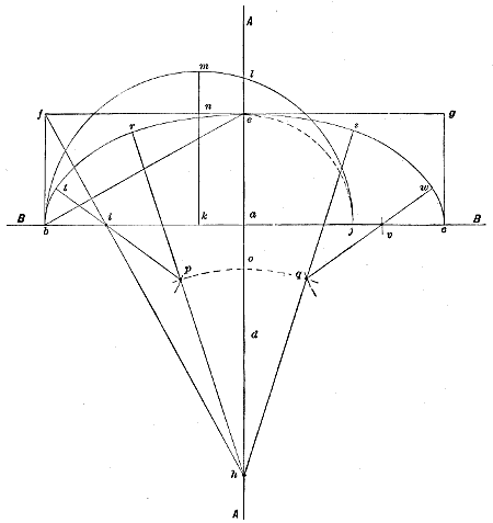
Fig. 194.
“In Fig. 194, a a and b b are centre lines passing through the major and minor axes of the ellipse, of which a is the axis or centre, b c is the major and a e half of the minor axis. Draw the rectangle b f g c, and then the diagonal line b e; at a right angle to b e draw line f h cutting b b at i. With radius a e and from a as a centre draw the dotted arc e j, giving the point j on the line b b. From centre k, which is on line b b, and central between b and j, draw the semicircle b m j, cutting a a at l. Draw the radius of the semicircle b m j cutting f g at n. With radius m n mark on a a, at and from a as a centre, the point o. With radius h o and from centre h draw the arc p o q. With radius a l and from b and c as centres draw arcs cutting p o q at the points p q. Draw the lines h p r and h q s, and also the lines p i t and q v w. From h as centre draw that part of the ellipse lying between r and s. With radius p r and from p as a centre draw that part of the ellipse lying between r and t. With radius q s and from q draw the ellipse from s to w. With radius i t and from i as a centre draw the ellipse from t to b. With radius v w and from v as a centre draw the ellipse from w to c, and one half the ellipse will be drawn. It will be seen that the whole construction has been performed to find the centres h p q i and v, and that while v and i may be used to carry the curve around the other side or half of the ellipse, new centres must be provided for h p and q; these new centres correspond in position to h p q.
“If it were possible to subdivide the ellipse into equal parts it would be unnecessary to resort to these processes of approximately representing the two curves by arcs of circles; but unless this be done, the spacing of the teeth can only be effected by the laborious process of stepping off the perimeter into such small subdivisions that the chords may be regarded as equal to the arcs, which after all is but an approximation; unless, indeed, we adopt the mechanical expedient of cutting out the ellipse in metal or other substance, measuring and subdividing it with a strip of paper or a steel tape, and wrapping back the divided measure in order to find the points of division on the curve.
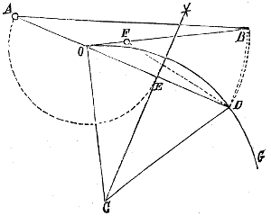
Fig. 195.
“But these circular arcs may be rectified and subdivided with great facility and accuracy by a very simple process, which we take from Prof. Rankine’s “Machinery and Mill Work,” and is illustrated in Fig. 195. Let o b be tangent at o to the arc o d, of which c is the centre. Draw the chord d o, bisect it in e, and produce it to a, making o a = o e; with centre a and radius a d describe an arc cutting the tangent in b; then o b will be very nearly equal in length to the arc o d, which, however, should not exceed about 60°; if it be 60°, the error is theoretically about 1⁄900 of the length of the arc, o b being so much too short; but this error varies with the fourth power of the angle subtended by the arc, so that for 30° it is reduced to 1⁄16 of that amount, that is, to 1⁄14400. Conversely, let o b be a tangent of given length; make o f = 1⁄4 o b; then with centre f and radius f b describe an arc cutting the circle o d g (tangent to o b at o) in the point d; then o d will be approximately equal to o b, the error being the same as in the other construction and following the same law.
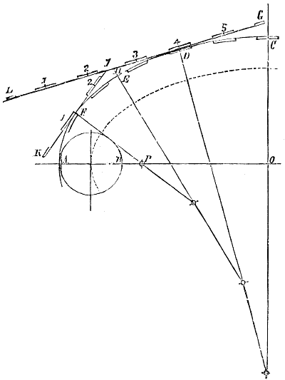
Fig. 196.
“The extreme simplicity of these two constructions and the facility with which they may be made with ordinary drawing instruments make them exceedingly convenient, and they should be more widely known than they are. Their application to the present problem is shown in Fig. 196, which represents a quadrant of an ellipse, the approximate arcs c d, d e, e f, f a having been determined by trial and error. In order to space this off, for the positions of the teeth, a tangent is drawn at d, upon which is constructed the rectification of d c, which is d g, and also that of d e in the opposite direction, that is, d h, by the process just explained. Then, drawing the tangent at f, we set off in the same manner f i = f e, and f k = f a, and then measuring h l = i k, we have finally g l, equal to the whole quadrant of the ellipse.
“Let it now be required to lay out 24 teeth upon this ellipse; that is, 6 in each quadrant; and for symmetry’s sake we will suppose that the centre of one tooth is to be at a, and that of another at c, Fig. 196. We therefore divide l g into six equal parts at the points 1, 2, 3, &c., which will be the centres of the teeth upon the rectified ellipse. It is practically necessary to make the spaces a little greater than the teeth; but if the greatest attainable exactness in the operation of the wheel is aimed at, it is important to observe that backlash, in elliptical gearing, has an effect quite different from that resulting in the case of circular wheels. When the pitch-curves are circles, they are always in contact; and we may, if we choose, make the tooth only half the breadth of the space, so long as its outline is correct. When the motion of the driver is reversed, the follower will stand still until the backlash is taken up, when the motion will go on with a perfectly constant velocity ratio as before. But in the ease of two elliptical wheels, if the follower stand still while the driver moves, which must happen when the motion is reversed if backlash exists, the pitch-curves are thrown out of contact, and, although the continuity of the motion will not be interrupted, the velocity ratio will be affected. If the motion is never to be reversed, the perfect law of the velocity ratio due to the elliptical pitch-curve may be preserved by reducing the thickness of the tooth, not equally on each side, as is done in circular wheels, but wholly on the side not in action. But if the machine must be capable of acting indifferently in both directions, the reduction must be made on both sides of the tooth: evidently the action will be slightly impaired, for which reason the backlash should be reduced to a minimum. Precisely what is the minimum is not so easy to say, as it evidently depends much upon the excellence of the tools and the skill of the workmen. In many treatises on constructive mechanism it is variously stated that the backlash should be from one-fifteenth to one-eleventh of the pitch, which would seem to be an ample allowance in reasonably good castings not intended to be finished, and quite excessive if the teeth are to be cut; nor is it very obvious that its amount should depend upon the pitch any more than upon the precession of the equinoxes. On paper, at any rate, we may reduce it to zero, and make the teeth and spaces equal in breadth, as shown in the figure, the teeth being indicated by the double lines. Those upon the portion l h are then laid off upon k i, after which these divisions are transferred to curves. And since under that condition the motion of this third line, relatively to each of the others, is the same as though it rolled along each of them separately while they remained fixed, the process of constructing the generated curves becomes comparatively simple. For the describing line, we naturally select a circle, which, in order to fulfil the condition, must be small enough to roll within the pitch ellipse; its diameter is determined by the consideration, that if it be equal to a p, the radius of the arc a f, the flanks of the teeth in that region will be radial. We have, therefore, chosen a circle whose diameter, a b, is three-fourths of a p, as shown, so that the teeth, even at the ends of the wheels, will be broader at the base than on the pitch line. This circle ought strictly to roll upon the true elliptical curve, and assuming as usual the tracing-point upon the circumference, the generated curves would vary slightly from true epicycloids, and no two of those used in the same quadrant of the ellipse would be exactly alike. Were it possible to divide the ellipse accurately, there would be no difficulty in laying out these curves; but having substituted the circular arcs, we must now roll the generating circle upon these as bases, thus forming true epicycloidal teeth, of which those lying upon the same approximating arc will be exactly alike. Should the junction of two of these arcs fall within the breadth of a tooth, as at d, evidently both the face and the flank on one side of that tooth will be different from those on the other side; should the junction coincide with the edge of a tooth, which is very nearly the case at f, then the face on that side will be the epicycloid belonging to one of the arcs, its flank a hypocycloid belonging to the other; and it is possible that either the face or the flank on one side should be generated by the rolling of the describing circle partly on one arc, partly on the one adjacent, which, upon a large scale and where the best results are aimed at, may make a sensible change in the form of the curve.
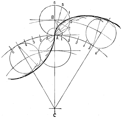
Fig. 197.
“The convenience of the constructions given in Fig. 194 is nowhere more apparent than in the drawing of the epicycloids, when, as in the case in hand, the base and generating circles may be of incommensurable diameters; for which reason we have, in Fig. 197, shown its application in connection with the most rapid and accurate mode yet known of describing those curves. Let c be the centre of the base circle; b that of the rolling one; a the point of contact. Divide the semi-circumference of b into six equal parts at 1, 2, 3, &c.; draw the common tangent at a, upon which rectify the arc a2 by process No. 1, then by process No. 2 set out an equal arc a2 on the base circle, and stepping it off three times to the right and left, bisect these spaces, thus making subdivisions on the base circle equal in length to those on the rolling one. Take in succession as radii the chords a1, a2, a3, &c., of the describing circle, and with centres 1, 2, 3, &c., on the base circle, strike arcs either externally or internally, as shown respectively on the right and left; the curve tangent to the external arcs is the epicycloid, that tangent to the internal ones the hypocycloid, forming the face and flank of a tooth for the base circle.
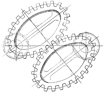
Fig. 198.
“In the diagram, Fig. 196, we have shown a part of an ellipse whose length is 10 inches and breadth 6, the figure being half size. In order to give an idea of the actual appearance of the combination when complete, we show in Fig. 198 the pair in gear, on a scale of 3 inches to the foot. The excessive eccentricity was selected merely for the purpose of illustration. Fig. 198 will serve also to call attention to another serious circumstance, which is that although the ellipses are alike, the wheels are not; nor can they be made so if there be an even number of teeth, for the obvious reason that a tooth upon one wheel must fit into a space on the other; and since in the first wheel, Fig. 196, we chose to place a tooth at the extremity of each axis, we must in the second one place there a space instead; because at one time the major axes must coincide, at another the minor axis, as in Fig. 191. If then we use even numbers, the distribution and even the forms of the teeth are not the same in the two wheels of the pair. But this complication may be avoided by using an odd number of teeth, since, placing a tooth at one extremity of the major axis, a space will come at the other.
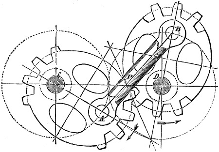
Fig. 199.
“It is not, however, always necessary to cut teeth all round these wheels, as will be seen by an examination of Fig. 199, c and d being the fixed centres of the two ellipses in contact at p. Now p must be on the line c d, whence, considering the free foci, we see p b is equal to p c, and p a to p d; and the common tangent at p makes equal angles with c p and p a, as is also with p b and p d; therefore, c d being a straight line, a b is also a straight line and equal to c d. If then the wheels be overhung, that is, fixed on the ends of the shafts outside the bearings, leaving the outer faces free, the moving foci may be connected by a rigid link a b, as shown.
“This link will then communicate the same motion that would result from the use of the complete elliptical wheels, and we may therefore dispense with most of the teeth, retaining only those near the extremities of the major axes which are necessary in order to assist and control the motion of the link at and near the dead-points. The arc of the pitch-curves through which the teeth must extend will vary with their eccentricity: but in many cases it would not be greater than that which in the approximation may be struck about one centre, so that, in fact, it would not be necessary to go through the process of rectifying and subdividing the quarter of the ellipse at all, as in this case it can make no possible difference whether the spacing adopted for the teeth to be cut would “come out even” or not if carried around the curve. By this expedient, then, we may save not only the trouble of drawing, but a great deal of labor in making, the teeth round the whole ellipse. We might even omit the intermediate portions of the pitch ellipses themselves; but as they move in rolling contact their retention can do no harm, and in one part of the movement will be beneficial, as they will do part of the work; for if, when turning, as shown by the arrows, we consider the wheel whose axis is d as the driver, it will be noted that its radius of contact, c p, is on the increase; and so long as this is the case the other wheel will be compelled to move by contact of the pitch lines, although the link be omitted. And even if teeth be cut all round the wheels, this link is a comparatively inexpensive and a useful addition to the combination, especially if the eccentricity be considerable. Of course the wheels shown in Fig. 198 might also have been made alike, by placing a tooth at one end of the major axis and a space at the other, as above suggested. In regard to the variation in the velocity ratio, it will be seen, by reference to Fig. 199, that if d be the axis of the driver, the follower will in the position there shown move faster, the ratio of the angular velocities being pd/pb; if the driver turn uniformly the velocity of the follower will diminish, until at the end of half a revolution, the velocity ratio will be pb/pd; in the other half of the revolution these changes will occur in a reverse order. But p d = l b; if then the centres b d are given in position, we know l p, the major axis; and in order to produce any assumed maximum or minimum velocity ratio, we have only to divide l p into segments whose ratio is equal to that assumed value, which will give the foci of the ellipse, whence the minor axis may be found and the curve described. For instance, in Fig. 198 the velocity ratio being nine to one at the maximum, the major axis is divided into two parts, of which one is nine times as long as the other; in Fig. 199 the ratio is as one to three, so that, the major axis being divided into four parts, the distance a c between the foci is equal to two of them, and the distance of either focus from the nearer extremity of the major axis equal to one, and from the more remote extremity equal to three of these parts.”
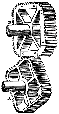
Fig. 200.
Another example of obtaining a variable motion is given in Fig. 200. The only condition necessary to the construction of wheels of this class is that the sum of the radii of the pitch circles on the line of centres shall equal the distance between the axes of the two wheels. The pitch curves are to be considered the same as pitch circles, “so that,” says Willis, “if any given circle or curve be assumed as a describing (or generating) curve, and if it be made to roll on the inside of one of these pitch curves and on the outside of the corresponding portion of the other pitch curve, then the motion communicated by the pressure and sliding contact of one of the curved teeth so traced upon the other will be exactly the same as that effected by the rolling contact (by friction) of the original pitch curves.”
It is obvious that on b the corner sections are formed of simple segments of a circle of which the centre is the axis of the shaft, and that the sections between them are simply racks. The corners of a are segments of a circle of which the axis of a is the centre, and the sections between the corners curves meeting the pitch circles of the rack at every point as it passes the line of centres.
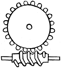
Fig. 201.
Intermittent motion may also be obtained by means of a worm-wheel constructed as in Fig. 201, the worm having its teeth at a right angle to its axis for a distance around the circumference proportioned to the required duration of the period of rest; or the motion may be made variable by giving the worm teeth different degrees of inclination (to the axis), on different portions of the circumference.
In addition to the simple operation of two or more wheels transmitting motion by rotating about their fixed centres and in fixed positions, the following examples of wheel motion may be given.
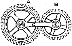
Fig. 202.
In Fig. 202 are two gear-wheels, a, which is fast upon its stationary shaft, and b, which is free to rotate upon its shaft, the link c affording journal bearing to the two shafts. Suppose that a has 40 teeth, while b has 20 teeth, and that the link c is rotated once around the axis of a, how many revolutions will b make? By reason of there being twice as many teeth in a as in b the latter will make two rotations, and in addition to this it will, by reason of its connection to the arm c, also make a revolution, these being two distinct motions, one a rotation of b about the axis of a, and the other two rotations of b upon its own axis.
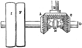
Fig. 203.
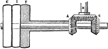
Fig. 204.
A simple arrangement of gearing for reversing the direction of rotation of a shaft is shown in Fig. 203. i and f are fast and loose pulleys for the shaft d, a and c are gears free to rotate upon d, n is a clutch driven by d; hence if n be moved so as to engage with c the latter will act as a driver to rotate the shaft b, the wheel upon b rotating a in an opposite direction to the rotation of d. But if n be moved to engage with a the latter becomes the driving wheel, and b will be caused to rotate in the opposite direction. Since, however, the engagement of the clutch n with the clutch on the nut of the gear-wheels is accompanied with a violent shock and with noise, a preferable arrangement is shown in Fig. 204, in which the gears are all fast to their shafts, and the driving shaft for c passes through the core or bore of that for a, which is a sleeve, so that when the driving belt acts upon pulley f the shaft b rotates in one direction, while when the belt acts upon e, b rotates in the opposite direction, i being a loose pulley.
If the speed of rotation of b require to be greater in one direction than in the other, then the bevel-wheel on b is made a double one, that is to say, it has two annular toothed surfaces on its radial face, one of larger diameter than the other; a gearing with one of these toothed surfaces, and c with the other. It is obvious that the pinions a c, being of equal diameters, that gearing with the surface or gear of largest diameter will give to b the slowest speed of rotation.
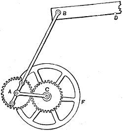
Fig. 205.
Fig. 205 represents Watt’s sun-and-planet motion for converting reciprocating into rotary motion; b d is the working beam of the engine, whose centre of motion is at d. The gear a is so connected to the connecting rod that it cannot rotate, and is kept in gear with the wheel c on the fly-wheel shaft by means of the link shown. The wheel a being prevented from rotation on its axis causes rotary motion to the wheel c, which makes two revolutions for one orbit of a.
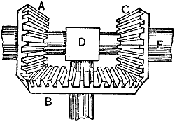
Fig. 206.
An arrangement for the rapid increase of motion by means of gears is shown in Fig. 206, in which a is a stationary gear, b is free to rotate upon its shaft, and being pivoted upon the shaft of a, at d, is capable of rotation around a while remaining in gear with c. Suppose now that the wheel a were absent, then if b were rotated around c with d as a centre of motion, c and its shaft e would make a revolution even though b would have no rotation upon its axis. But a will cause b to rotate upon its axis and thus communicate a second degree of motion to c, with the result that one revolution of b causes two rotations of c.
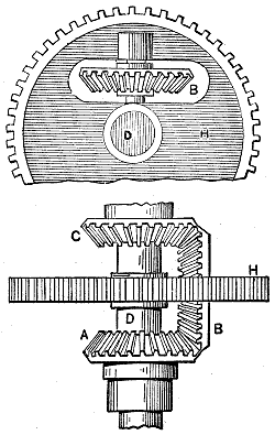
Fig. 207.
The relation of motion between b and c is in this case constant (2 to 1), but this relation may be made variable by a construction such as shown in Fig. 207, in which the wheel b is carried in a gear-wheel h, which rides upon the shaft d. Suppose now that h remains stationary while a revolves, then motion will be transmitted through b to c, and this motion will be constant and in proportion to the relative diameters of a and c. But suppose by means of an independent pinion the wheel h be rotated upon its axis, then increased motion will be imparted to c, and the amount of the increase will be determined by the speed of rotation of h, which may be made variable by means of cone pulleys or other suitable mechanical devices.
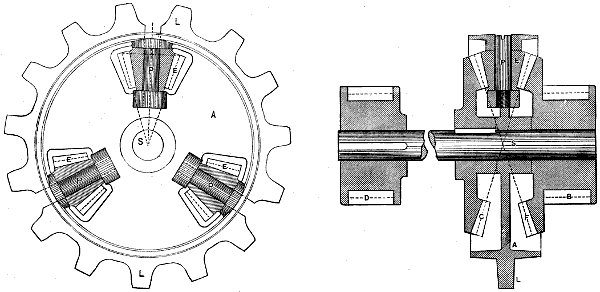
Fig. 208.
Fig. 208 represents an arrangement of gearing used upon steam fire-engines and traction engines to enable them to turn easily in a short radius, as in turning corners in narrow streets. The object is to enable the driving wheel on either side of the engine to increase or diminish its rotation to suit the conditions caused by the leading or front pair of steering wheels.
In the figures a is a plate wheel having the lugs l, by means of which it may be rotated by a chain. a is a working fit on the shaft s, and carries three pinions e pivoted upon their axes p. f is a bevel-gear, a working fit on s, while c is a similar gear fast to s. The pinions b, d are to drive gears on the wheels of the engine, the wheels being a working fit on the axle. Let it now be noted that if s be rotated, c and f will rotate in opposite directions and a will remain stationary. But if a be rotated, then all the gears will rotate with it, but e will not rotate upon p unless there be an unequal resistance to the motion of pinions d and b. So soon, however, as there exists an inequality of resistance between d and b then pinions e operate. For example, let b have more resistance than d, and b will rotate more slowly, causing pinion e to rotate and move c faster than is due to the motion of the chain wheel a, thus causing the wheel on one side of the engine to retard and the other to increase its motion, and thus enable the engine to turn easily. From its action this arrangement is termed the equalizing gear.
In Figs. 209 to 214 are shown what are known as mangle-wheels from their having been first used in clothes mangling machines.
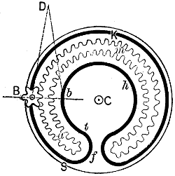
Fig. 209.
The mangle-wheel[10] in its simplest form is a revolving disc of metal with a centre of motion c (Fig. 209). Upon the face of the disc is fixed a projecting annulus a m, the outer and inner edges of which are cut into teeth. This annulus is interrupted at f, and the teeth are continued round the edges of the interrupted portion so as to form a continued series passing from the outer to the inner edge and back again.
A pinion b, whose teeth are of the same pitch as those of the wheel, is fixed to the end of an axis, and this axis is mounted so as to allow of a short travelling motion in the direction b c. This may be effected by supporting this end of it either in a swing-frame moving upon a centre as at d, or in a sliding piece, according to the nature of the train with which it is connected. A short pivot projects from the centre of the pinion, and this rests in and is guided by a groove b s f t b h k, which is cut in the surface of the disc, and made concentric to the pitch circles of the inner and outer rays of teeth, and at a normal distance from them equal to the pitch radius of the pinion.
Now when the pinion revolves it will, if it be on the outside, as in Fig. 209, act upon the spur teeth and turn the wheel in the opposite direction to its own, but when the interrupted portion f of the teeth is thus brought to the pinion the groove will guide the pinion while it passes from the outside to the inside, and thus bring its teeth into action with the annular or internal teeth. The wheel will then receive motion in the same direction as that of the pinion, and this will continue until the gap f is again brought to the pinion, when the latter will be carried outwards and the motion again be reversed. The velocity ratio in either direction will remain constant, but the ratio when the pinion is inside will differ slightly from the ratio when it is outside, because the pitch radius of the annular or internal teeth is necessarily somewhat less than that of the spur teeth. However, the change of direction is not instantaneous, for the form of the groove s f t, which connects the inner and outer grooves, is a semicircle, and when the axis of the pinion reaches s the velocity of the mangle-wheel begins to diminish gradually until it is brought to rest at f, and is again gradually set in motion from f to t, when the constant ratio begins; and this retardation will be increased by increasing the difference between the radius of the inner and outer pitch circles.
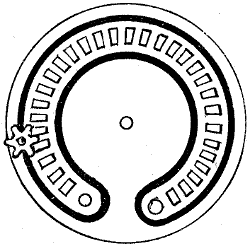
Fig. 210.
The teeth of a mangle-wheel are, however, most commonly formed by pins projecting from the face of the disc as in Fig. 210. In this manner the pitch circles for the inner and outer wheels coincide, and therefore the velocity ratio is the same within and without, also the space through which the pinion moves in shifting is reduced.
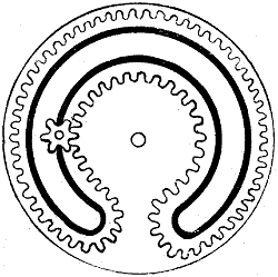
Fig. 211.
This space may be still further reduced by arranging the teeth as in Fig. 211, that is, by placing the spur-wheel within the annular or internal one; but at the same time the difference of the two velocity ratios is increased.
If it be required that the velocity ratio vary, then the pitch lines of the mangle-wheel must no longer be concentric.
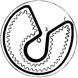
Fig. 212.
Thus in Fig. 212 the groove k l is directed to the centre of the mangle-wheel, and therefore the pinion will proceed during this portion of its path without giving any motion to the wheel, and in the other lines of teeth the pitch radius varies, hence the angular velocity ratio will vary.
In Figs. 209, 210, and 211 the curves of the teeth are readily obtained by employing the same describing circle for the whole of them. But when the form Fig. 212 is adopted, the shape of the teeth requires some consideration.
Every tooth of such a mangle-wheel may be considered as formed of two ordinary teeth set back to back, the pitch line passing through the middle. The outer half, therefore, appropriated to the action of the pinion on the outside of the wheel, resembles that portion of an ordinary spur-wheel tooth that lies beyond its pitch line, and the inner half which receives the inside action of the pinion resembles the half of an annular wheel that lies within the pitch circle. But the consequence of this arrangement is, that in both positions the action of the driving teeth must be confined to the approach of its teeth to the line of centres, and consequently these teeth must be wholly within their pitch line.
To obtain the forms of the teeth, therefore, take any convenient describing circle, and employ it to describe the teeth of the pinion by rolling within its pitch circle, and to describe the teeth of the wheel by rolling within and without its pitch circle, and the pinion will then work truly with the teeth of the wheel in both positions. The tooth at each extremity of the series must be a circular one, whose centre lies on the pitch line and whose diameter is equal to half the pitch.
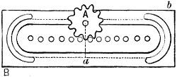
Fig. 213.
If the reciprocating piece move in a straight line, as it very often does, then the mangle-wheel is transformed into a mangle-rack (Fig. 213) and its teeth may be simply made cylindrical pins, which those of the mangle-wheel do not admit of on correct principle. b b is the sliding piece, and a the driving pinion, whose axis must have the power of shifting from a to a through a space equal to its own diameter, to allow of the change from one side of the rack to the other at each extremity of the motion. The teeth of the mangle-rack may receive any of the forms which are given to common rack-teeth, if the arrangement be derived from either Fig. 210 or Fig. 211.
But the mangle-rack admits of an arrangement by which the shifting motion of the driving pinion, which is often inconvenient, may be dispensed with.
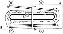
Fig. 214.
b b Fig. 214, is the piece which receives the reciprocating motion, and which may be either guided between rollers, as shown, or in any other usual way; a the driving pinion, whose axis of motion is fixed; the mangle rack c c is formed upon a separate plate, and in this example has the teeth upon the inside of the projecting ridge which borders it, and the guide-groove formed within the ring of teeth, similar to Fig. 211.
This rack is connected with the piece b b in such a manner as to allow of a short transverse motion with respect to that piece, by which the pinion, when it arrives at either end of the course, is enabled by shifting the rack to follow the course of the guide-groove, and thus to reverse the motion by acting upon the opposite row of teeth.
The best mode of connecting the rack and its sliding piece is that represented in the figure, and is the same which is adopted in the well-known cylinder printing-engines of Mr. Cowper. Two guide-rods k c, k c are jointed at one end k k to the reciprocating piece b b, and at the other end c c to the shifting-rack; these rods are moreover connected by a rod m m which is jointed to each midway between their extremities, so that the angular motion of these guide-rods round their centres k k will be the same; and as the angular motion is small and the rods nearly parallel to the path of the slide, their extremities c c may be supposed to move at a right angle to that path, and consequently the rack which is jointed to those extremities will also move upon b b in a direction at a right angle to its path, which is the thing required, and admits of no other motion with respect to b b.
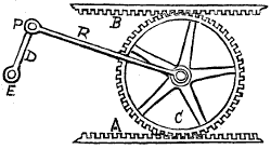
Fig. 215.
To multiply plane motion the construction shown in Fig. 215 is frequently employed. a and b are two racks, and c is a wheel between them pivoted upon the rod r. A crank shaft or lever d is pivoted at e and also (at p) to r. If d be operated c traverses along a and also rotates upon its axis, thus giving to b a velocity equal to twice that of the lateral motion of c.
The diameter of the wheel is immaterial, for the motion of b will always be twice that of c.
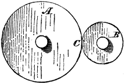
Fig. 216.
Friction gearing-wheels which communicate motion one to the other by simple contact of their surfaces are termed friction-wheels, or friction-gearing. Thus in Fig. 216 let a and b be two wheels that touch each other at c, each being suspended upon a central shaft; then if either be made to revolve, it will cause the other to revolve also, by the friction of the surfaces meeting at c. The degree of force which will be thus conveyed from one to the other will depend upon the character of the surface and the length of the line of contact at c.
These surfaces should be made as concentric to the axis of the wheel and as flat and smooth as possible in order to obtain a maximum power of transmission. Mr. E. S. Wicklin states that under these conditions and proper forms of construction as much as 300 horse-power may be (and is in some of the Western States) transmitted.
In practice, small wheels of this class are often covered with some softer material, as leather; sometimes one wheel only is so covered, and it is preferred that the covered wheel drive the iron one, because, if a slip takes place and the iron wheel was the driver, it would be apt to wear a concave spot in the wood covered one, and the friction between the two would be so greatly diminished that there would be difficulty in starting them when the damaged spot was on the line of centre.
If, however, the iron wheel ceased motion, the wooden one continuing to revolve, the damage would be spread over that part of the circumference of the wooden one which continued while the iron one was at rest, and if this occurred throughout a whole revolution of the wooden wheel its roundness would not be apt to be impaired, except in so far as differences in the hardness of the wood and similar causes might effect.
“To select the best material for driving pulleys in friction-gearing has required considerable experience; nor is it certain that this object has yet been attained. Few, if any, well-arranged and careful experiments have been made with a view of determining the comparative value of different materials as a frictional medium for driving iron pulleys. The various theories and notions of builders have, however, caused the application to this use of several varieties of wood, and also of leather, india-rubber, and paper; and thus an opportunity has been given to judge of their different degrees of efficiency. The materials most easily obtained, and most used, are the different varieties of wood, and of these several have given good results.
“For driving light machinery, running at high speed, as in sash, door, and blind factories, basswood, the linden of the Southern and Middle States (Tilia Americana) has been found to possess good qualities, having considerable durability and being unsurpassed in the smoothness and softness of its movement. Cotton wood (Populus monilifera) has been tried for small machinery with results somewhat similar to those of basswood, but is found to be more affected by atmospheric changes. And even white pine makes a driving surface which is, considering the softness of the wood, of astonishing efficiency and durability. But for all heavy work, where from twenty to sixty horse-power is transmitted by a single contact, soft maple (Acer rubrum) has, at present, no rival. Driving pulleys of this wood, if correctly proportioned and well built, will run for years with no perceptible wear.
“For very small pulleys, leather is an excellent driver and is very durable; and rubber also possesses great adhesion as a driver; but a surface of soft rubber undoubtedly requires more power than one of a less elastic substance.
“Recently paper has been introduced as a driver for small machinery, and has been applied in some situations where the test was most severe; and the remarkable manner in which it has thus far withstood the severity of these tests appears to point to it as the most efficient material yet tried.
“The proportioning, however, of friction-pulleys to the work required and their substantial and accurate construction are matters of perhaps more importance than the selection of material.
“Friction-wheels must be most accurately and substantially made and kept in perfect line so that the contact between the surfaces may not be diminished. The bodies are usually of iron lagged or covered with wooden segments.
“All large drivers, say from four to ten feet diameter and from twelve to thirty inch face, should have rims of soft maple six or seven inches deep. These should be made up of plank, one and a half or two inches thick, cut into ‘cants,’ one-sixth, eighth, or tenth of the circle, so as to place the grain of the wood as nearly as practicable in the direction of the circumference. The cants should be closely fitted, and put together with white lead or glue, strongly nailed and bolted. The wooden rim, thus made up to within about three inches of the width required for the finished pulley, is mounted upon one or two heavy iron ‘spiders,’ with six or eight radial arms. If the pulley is above six feet in diameter, there should be eight arms, and two spiders when the width of face is more than eighteen inches.
“Upon the ends of the arms are flat ‘pads,’ which should be of just sufficient width to extend across the inner face of the wooden rim, as described; that is, three inches less than the width of the finished pulley. These pads are gained into the inner side of the rim; the gains being cut large enough to admit keys under and beside the pads. When the keys are well driven, strong ‘lag’ screws are put through the ends of the arm into the rim. This done, an additional ‘round’ is put upon each side of the rim to cover bolt heads and secure the keys from ever working out. The pulley is now put to its place on the shaft and keyed, the edges trued up, and the face turned off with the utmost exactness.
“For small drivers, the best construction is to make an iron pulley of about eight inches less diameter and three inches less face than the pulley required. Have four lugs, about an inch square, cast across the face of this pulley. Make a wooden rim, four inches deep, with face equal to that of the iron pulley, and the inside diameter equal to the outer diameter of the iron. Drive this rim snugly on over the rim of the iron pulley having cut gains to receive the lugs, together with a hard wood key beside each. Now add a round of cants upon each side, with their inner diameter less than the first, so as to cover the iron rim. If the pulley is designed for heavy work, the wood should be maple, and should be well fastened by lag screws put through the iron rim; but for light work, it may be of basswood or pine, and the lag screws omitted. But in all cases, the wood should be thoroughly seasoned.
“In the early use of friction-gearing, when it was used only as backing gear in saw-mills, and for hoisting in grist-mills, the pulleys were made so as to present the head of the wood to the surface; and we occasionally yet meet with an instance where they are so made. But such pulleys never run so smoothly nor drive so well as those made with the fibre more nearly in a line with the work.”[11]
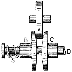
Fig. 217.
The driving friction may be obtained from contact of the radial surfaces in two ways: thus, Fig. 217 represents three discs, a, b, and c; the edge of a being gripped by and between b and c, which must be held together by a spiral spring s or other equivalent device. These wheels may be made to give a variable speed of rotation by curving the surfaces of the pair b c as in the figure. By means of suitable lever-motion a may be made to advance towards or recede from the centre of b and c, giving to their shaft an increased or diminished speed of revolution.
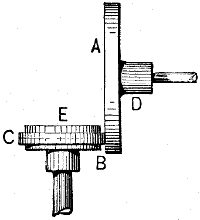
Fig. 218.
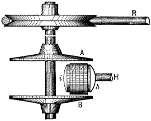
Fig. 219.
A similar result may be obtained by the construction shown in Fig. 218, in which d and e are two discs fast upon their respective shafts, and c are discs of leather clamped in e. It is obvious that if d be the driver the speed of revolution of e will be diminished in proportion as it is moved nearer to the centre of d, and also that the direction of revolution of d remaining constant, that of e will be in one direction if on the side b of the centre of d, and in the other direction if it is on the side a of the centre of d, thus affording means of reversing the motion as well as of varying its speed. A similar arrangement is sometimes employed to enable the direction of rotation of the driver shaft to be reversed, or its motion to cease. Thus, in Fig. 219, r is a driving rope driving the discs a, b, and c, d, e, f, g are discs of yellow pine clamped between the flanges h i; when these five discs are forced (by lifting shaft h), against the face of a motion occurs in one direction, while if forced against b the direction of motion of h is reversed.
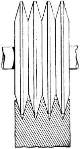
Fig. 220.
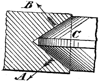
Fig. 221.
For many purposes, such as hoisting, for example, where considerable power requires to be transmitted, the form of friction wheels shown in Fig. 220 is employed, the object being to increase the line of contact between wheels of a given width of face. In this case the strain due to the length of the line of contact partly counteracts itself, thus relieving to that extent the journals from friction. Thus in Fig. 221 is shown a single wedge and groove of a pair of wheels. The surface pressure on each side will be at a right angle to the face, or in the direction described by the arrows a and b. The surface contact acts to thrust the bearings of the two shafts apart. The effective length of surface acting to thrust the bearings apart being denoted by the dotted line c. The relative efficiency of this class of wheel, however, is not to be measured by the length of the line c, as compared to that of the two contacting sides of the groove, because it is increased from the wedge shape of the groove, and furthermore, no matter how solid the wheels may be, there will be some elasticity which will operate to increase the driving power due to the contact. It is to preserve the wedge principle that the wedges are made flat at the top, so that they shall not bottom in the grooves even after considerable wear has taken place. The object of employing this class of gear is to avoid noise and jar and to insure a uniform motion. The motion at the line of contact of such wheels is not a rolling, but, in part, a sliding one, which may readily be perceived from a consideration of the following. The circumference of the top of each wedge is greater than that of the bottom, and, in the case of the groove, the circumference of the top is greater than that of the bottom; and since the top or largest circumference of one contacts with the smallest circumference of the other, it follows that the difference between the two represents the amount of sliding motion that occurs in each revolution. Suppose, for example, we take two of such wheels 10 inches in diameter, having wedges and grooves 1⁄4 inch high and deep respectively; then the top of the groove will travel 31.416 inches in a revolution, and it will contact with the bottom of the wedge which travels (on account of its lesser diameter) 29.845 inches per revolution.
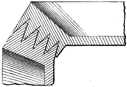
Fig. 222.
Fig. 222 shows the construction for a pair of bevel wheels on the same principle.
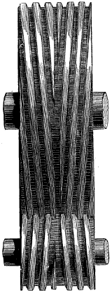
Fig. 223.
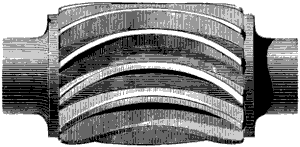
Fig. 224.
A form of friction-gearing in which the journals are relieved of the strain due to the pressure of contact, and in which slip is impossible, is shown in Fig. 223. It consists of projections on one wheel and corresponding depressions or cavities on the other. These projections and cavities are at opposite angles on each half of each wheel, so as to avoid the end pressure on the journals which would otherwise ensue. Their shapes may be formed at will, providing that the tops of the projections are narrower than their bases, which is necessary to enable the projections to enter and leave the cavities. In this class of positive gear great truth or exactness is possible, because both the projections and cavities may be turned in a lathe. Fig. 224 represents a similar kind of gear with the projections running lengthways of the cylinder approaching more nearly in its action to toothed gearing, and in this case the curves for the teeth and groves should be formed by the rules already laid down for toothed gearing. The action of this latter class may be made very smooth, because a continuous contact on the line of centres may be maintained by reason of the longitudinal curve of the teeth.
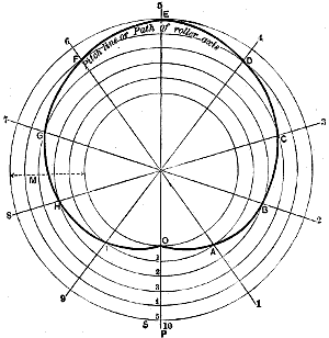
Fig. 225.
Cams may be employed to impart either a uniform, an irregular, or an intermittent motion, the principles involved in their construction being as follows:—Let it be required to construct a cam that being revolved at a uniform velocity shall impart a uniform reciprocating motion. First draw an inner circle o, Fig. 225, whose radius must equal the radius of the shaft that is to drive it, plus the depth of the cam at its shallowest part, plus the radius of the roller the cam is to actuate. Then from the same centre draw an outer circle s, the radius between these two circles being equal to the amount the cam is to move the roller. Draw a line o p, and divide it into any convenient numbers of divisions (five being shown in the figure), and through these points draw circles. Divide the outer circle s into twice as many equal divisions as the line o p is divided into (as from 1 to 10 in the figure), and where these lines pass through the circles will be points through which the pitch line of the cam may be drawn.
Thus where circle 1 meets line 1, or at point a, is one point in the pitch line of the cam; where circle 2 meets line 2, or at b, is another point in the pitch line of the cam, and so on until we reach the point e, where circle 5 meets line 5. From this point we simply repeat the process, the point e where line 6 cuts circle 4, being a point on the pitch line, and so on throughout the whole 10 divisions, and through the points so obtained we draw the pitch line.
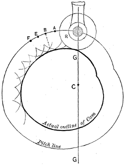
Fig. 226.
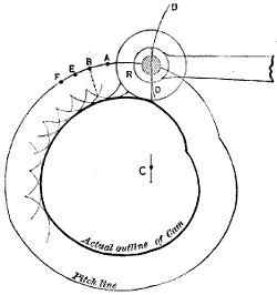
Fig. 227.
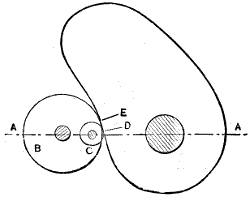
Fig. 228.
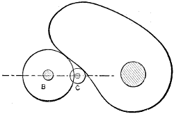
Fig. 229.
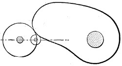
Fig. 230.
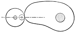
Fig. 231.
If we were to cut out a cam to the outline thus obtained, and revolve it at a uniform velocity, it would move a point held against its perimeter at a uniform velocity throughout the whole of the cam revolution. But such a point would rapidly become worn away and dulled, which would, as the point broadened, vary the motion imparted to it, as will be seen presently. To avoid this wear a roller is used in place of a point, and the diameter of the roller affects the action of the cam, causing it to accelerate the cam action at one and retard it at another part of the cam revolution, hence the pitch line obtained by the process in Fig. 225 represents the path of the centre of the roller, and from this pitch line we may mark out the actual cam by the construction shown in Fig. 226. A pair of compasses are set to the radius of the roller r, and from points (such as at a, b, e, f), as the pitch line, arcs of circles are struck, and a line drawn to just meet the crowns of these arcs will give the outline of the actual cam. The motion of the roller, however, in approaching and receding from the cam centre c, must be in a straight line g g that passes through the centre c of the cam. Suppose, for example, that instead of the roller lifting and falling in the line g g its arm is horizontal, as in Fig. 227, and that this arm being pivoted the roller moves in an arc of a circle as d d, and the motion imparted to the arm will no longer be uniform. Furthermore, different diameters of roller require different forms of cam to accomplish the same motion, or, in other words, with a given cam the action will vary with different diameters of roller. Suppose, for example, that in Fig. 228 we have a cam that is to operate a roller along the line a a, and that b represents a large and c a small roller, and with the cam in the position shown in the figure, c will have contact with the cam edge at point d, while b will have contact at the point e, and it follows that on account of the enlarged diameter of roller b over roller c, its action is at this point quicker under a given amount of cam motion, which has occurred because the point of contact has advanced upon the roller surface—rolling along it, as it were. In Fig. 229 we find that as the cam moves forward this action continues on both the large and the small roller, its effect being greater upon the large than upon the small one, and as this rolling motion of the point of contact evidently occurs easily, a quick roller motion is obtained without shock or vibration. Continuing the cam motion, we find in Fig. 230 that the point of contact is receding toward the line of motion on the large roller and advancing upon the small one, while in Fig. 231 the two have contact at about the same point, the forward motion being about completed.
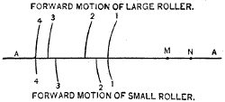
Fig. 232.
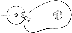
Fig. 233.
To compare the motions of the respective rollers along the line of motion a a we proceed as in Fig. 232, in which the two dots m and n are the same distance apart as are the centres of the two rollers b and c when in the positions they occupy in Fig. 228; hence a pair of compasses set to the radius from the axis of the cam to that of roller b will, if rested at n, strike the arc marked 1 above the line of motion a a, while a pair of compasses set to the radius from the axis of the cam to that of roller c in Fig. 228 will, if rested at m in Fig. 232, mark the arc 1 below the line of motion a a. Continuing this process, we set the compasses to the radius from the axis of the cam to that of roller b in Fig. 229, and mark this radius at arc 2 above the line a a in Fig. 232; hence the distance apart of these two arcs is the amount the roller travelled along the line a a while the cam moved from its position in Fig. 228 to its position in Fig. 229. Next we set the compasses from the axis of the cam to that of the large roller in Fig. 230, and then mark arc 3 above the line in Fig. 232, and repeat the process for Fig. 233, thus using the centre n for all the positions of the large roller and marking its motion above the line a a. To get the motion of the small roller c, we set the compasses to the radius from the axis of the cam to the small roller in Fig. 228, and then resting one point of these compasses on centre m in Fig. 232, we mark arc 1 below the line a a. Turning to Fig. 229 we set the compasses from the cam axis to the centre of roller c, and from centre n in Fig. 232 mark arc 2 below line a. From Figs. 230 and 231 proceed in the same way to get lines 3 and 4 below line a in Fig. 232, and we may at once compare the two motions. Thus we find that while the cam moved from the position in Fig. 228 to that in Fig. 229, the large roller moved twice as far as the small one, while at 230 the motions were rapidly equalizing again, the equalization being completed at 231.
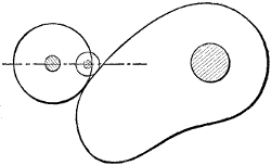
Fig. 234.
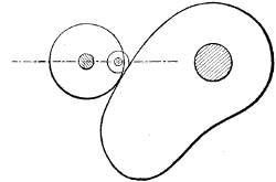
Fig. 235.
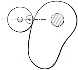
Fig. 236.
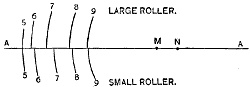
Fig. 237.
We may now consider the return motion, and in Fig. 233 we find that the order of things is reversed, for the small roller has contact at o, while the large one has contact at p; hence the small one leads and gives the most rapid motion, which it continues to do, as is shown in Figs. 234, 235, and 236, and we may plot out the two motions as in Fig. 237—that for the large roller being above and that for the small one below the line a a. First we set a pair of compasses to the radius from the axis of the large and small roller when in the position shown in Fig. 231 (which corresponds to the same radius in Fig. 228), and mark two centres, m and n, as we did in Fig. 232. Of these n is the centre for plotting the motion of the large roller and m the centre for plotting the motion of the small one. We set a pair of compasses to the radius from the axis of the cam and that of the large roller in Fig. 231, and then resting the compasses at n we mark arc 5 above the line a a, Fig. 237. The compasses are then set from the cam to the roller axis in Fig. 233, and arc 6 is marked above line a a. From Figs. 234, 235, and 236 we get the radii to mark arcs 7, 8, 9 above a a, and the motion of the large roller is plotted. We proceed in the same way for the small one, but use the centre m, Fig. 237, to mark the arcs 5, 6, 7, 8, and 9 below the line a a, and find that the small roller has moved quickest throughout. It appears, then, that the larger the roller the quicker the forward motion and the slower the return one, which is advantageous, because the object is to move the roller out quickly and close it slowly, so that under a quick speed the cam shall not run away from the roller as it is apt to do in the absence of a return or backing cam, which consists of a separate cam for moving the roller on its return stroke, thus dispensing with the use of springs or weights to keep the roller upon the cam and making the motion positive.
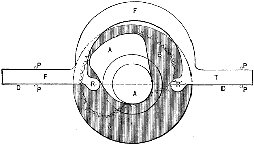
Fig. 238.
The return or backing cam obviously depends for its shape upon the forward cam, and the latter having been determined, the requisite form for the return cam may be found as follows. In Fig. 238 let a represent the forward cam fastened in any suitable or convenient way to a disc of paper, or, what is better, sheet zinc, b. The cam is pivoted by a pin passing through it and the zinc, and driven into the drawing-board. A frame f is made to carry two rollers r and r′, whose width apart exactly equals the extreme length of the forward cam. The faces d d of the frame f are in a line with a line passing through the centres of the rolls r r′, and the cam is also pivoted on this line, so that when the four pins p are driven into the drawing-board, the frame f will be guided by them to move in a line that crosses the centre of the cam a. Suppose then that, the pieces occupying the position shown in the engraving, we slide f so that roller r touches the edge of cam a, and we may then take a needle and mark an arc or line around the edge of r′. We then revolve cam a a trifle, and, being fast to b, the two will move together, and with r against a we mark a second arc, coincident with the edge of roller r′. By continuing this process we mark the numerous short arcs shown upon b, and the crowns of these arcs give us the outline of the return cam. It is obvious that, while the edge of the cam a will not let roller r (and therefore frame f) move to the right, roller r′ being against the edge of the backing or return cam as marked upon b, prevents the frame f from moving to the left; hence neither roll can leave its cam.
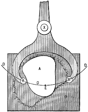
Fig. 239.
We have in this example supposed that the frame carrying the rollers is guided to move in a straight line, and it remains to give an example in which the rollers are carried on a pivoted shaft or rocking arm. In Fig. 239 we have the same cam a with a sheet of paper b fastened to it, the rollers r r′ being carried in a rock shaft pivoted at x. It is essential in this case that the rollers r and r′ and the centre upon which the cam revolves shall all three be in the arc of a circle whose centre is the axis of x, as is denoted by the arc d. The cam a is fastened to the piece of stiff paper or of sheet zinc b, and the two are pivoted by a pin passing through the axis e of the cam and into the drawing-board, while the lever is pivoted at x by a pin passing into the drawing-board. The backing or return cam is obviously marked out the same way as was described with reference to Fig. 238.
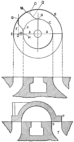
Fig. 240.
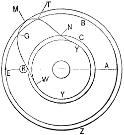
Fig. 241.
In Fig. 240 we have as an example the construction of a cam to operate the slide valve of an engine which is to have the steam supply to the cylinder cut off at one-half the piston stroke, and that will admit the live steam as quickly as a valve having steam lap equal to, say, three-fourths the width of the port. In Fig. 240 let the line a represent a piston stroke of 24 inches, the outer circle b the path of the outer edge of the cam, and the inner circle c the inner edge of the cam, the radius between these circles representing the full width of the steam port. Now, in a valve having lap equal to three-fourths the width of the steam port, and travel enough to open both ports fully, the piston of a 24-inch-stroke engine will have moved about 2 inches before the steam port is fully opened, and to construct a cam that will effect the same movement we mark a dot d, distant from the end e of piston stroke 2⁄26 of the length of the line a, and by erecting the line f we get at point g, the point at which the cam must attain its greatest throw. It is obvious, therefore, that as the roller is at r the valve will be in mid-position, as shown at the bottom of the figure, and that when point g of the cam arrives at e the edge p of the valve will be moved fair with edge s of the steam port t, which will therefore be full open. To cut off at half stroke the valve must again be closed by the time point n of the cam meets the roller r; hence we may mark point n. We may then mark in the cam curve from n to m, making it as short as it will work properly without causing the roller to fail to follow the curve or strike a blow when reaching the circle c. To accomplish this end in a single cam, it is essential to make the curve as gradual as possible from point m to o, so as to start the roller motion easily. But once having fairly started, its motion may be rapidly accelerated, the descent from o to q being rapid. To prevent the roller from meeting circle c with a blow, the curve from q to n is again made gradual, so as to ease and retard the roller motion. The same remarks apply to the curve from r to g, the object being to cause the roller to begin and end its passage along the cam curve as slowly as the length of cam edge occupied by the curve will permit. There is one objection to starting the curve slowly at g, which is that the port s will be opened correspondingly slowly for the live steam. This, however, may be overcome by giving the valve an increased travel, as shown in Fig. 241, which will simply cause the valve edge to travel to a corresponding amount over the inside edge of the port. The increased travel is shown by the circles y and z, and it is seen that the cam curve from w to r is more gradual than in Fig. 240, while the roller r will be moved much more quickly in the position shown in Fig. 241 than it will in that shown in Fig. 240, both positions being that when the piston is at the end of the stroke and the port about to open. While that part of the cam curve from g to m in Fig. 241 is moving past the roller r, the valve will be moving over the bridge, the steam port remaining wide open, and therefore not affecting the steam distribution. After point m, Fig. 241, has passed the roller, we have from m to t to start the roller gradually, so that when it has arrived at t and the port begins to close for the cut-off it may move rapidly, and continue to do so until the point n reaches the roller and the cut-off has occurred, after which it does not matter how slowly the valve moves; hence we may make the curve from n to the circle y as gradual as we like.
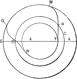
Fig. 242.
Fig. 242 represents a cam for a valve having the amount of lap represented by the distance between circles c and y, the cam occupying the position it would do with the piston at one end of the stroke, as at e. Obviously, a full port is obtained when point g reaches the roller, and as point n is distant from e three-quarters of the diameter of the outer circle, the cut-off occurs at three-quarter stroke, and we have from n to y to make the curve as gradual as we like, and from w to r in moving the valve to open the port. We cannot, however, give more gradual curves at g and at m without retarding the roller motion, and therefore opening and closing the port slower, and it would simply be a matter of increase of speed to cause the roller to fail to follow the cam surface at these two points unless a return cam be employed.
We have in these engine cams considered the steam supply and point of cut-off only, and it is obvious that a second and separate cam would be required to operate the exhaust valves.
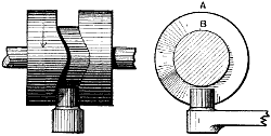
Fig. 243.
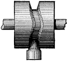
Fig. 244.
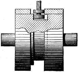
Fig. 245.
Fig. 243 represents a groove-cam, and it is to be observed that the roller cannot be maintained in a close fit in the groove, because the friction on its two sides endeavours to drive it in opposite directions at the same time, causing an abrasion that soon widens the groove and reduces the roller diameter; furthermore, when the grooves are made of equal width all the way down (and these cams are often made in this way) the roller cannot have a rolling action only, but must have some sliding motion. Thus, referring to Fig. 243, the amount of sliding motion will be equal to the differences in the circumferences of the outer circle a and the inner one b. To obviate this the groove and roller must be made of such a taper that the axis of the cam and of the roller will meet on the line of the cam axes and in the middle of the width, as is shown in Fig. 244; but even in this case the cam will grind away the roller to some extent, on account of rubbing its sides in opposite directions. To obviate this, Mr. James Brady, of Brooklyn, N. Y., has patented the use of two rollers, as in Fig. 245, one acting against one side and the other against the other side of the groove, by which means lost motion and rapid wear are successfully avoided.
In making a cam of this form, the body of the cam is covered by a sleeve. The groove is cut through the sleeve and into the body, and is made wider than the diameter of the roller. When the rollers are in place on the spindle or journal, the sleeve is pushed forward, or rather endways, and fastened by a set-screw. This gives the desired bearing on both sides of the groove, while each roller touches one side only of the groove. The edges of the sleeve are then faced off even with the cam body, the whole appearing as in the figure.
VOL. I. FORMS OF SCREW THREADS. PLATE II.
THE V-THREAD. THE UNITED STATES STANDARD THREAD.
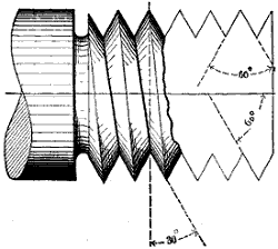
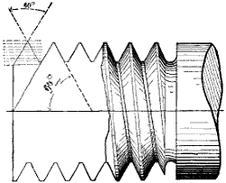
Fig. 246. Fig. 247.
THE WHITWORTH, OR ENGLISH STANDARD THREAD. THE SQUARE THREAD.
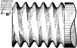
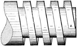
Fig. 248. Fig. 249.
THE PITCH OF A THREAD. A DOUBLE THREAD.
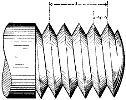
Fig. 250. Fig. 251.
THE RATCHET THREAD. A “DRUNKEN” THREAD.
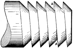
Fig. 252. Fig. 253.
RIGHT AND LEFT HAND THREAD.
Fig. 254.