Volume 1 — Chapter XII.—EXAMPLES IN LATHE WORK.
Reading edition
Technical Terms used with Reference to Lathe Work.—Work held between the lathe centres is said to run true, when a fixed point set to touch its perimeter will have an equal degree of contact all around the circumference, and at any part of the length of the same when the work is cylindrical and is rotated. When such a fixed point has contact at one part more than at another of the work circumference, it is said to run “out of true,” “out of truth,” or not to run true.
Radial or side faces (as they are sometimes called) also run true when a fixed point has equal contact (at all parts of the revolution) with the work surface.
Work that is held in chucks is said to be set true when it is adjusted in the intended position.
To true up is to take off the work a cut of sufficient depth to cause a fixed point to touch the work surface equally at each point in the revolution.
To clean work up is to take off it a cut sufficiently deep to cause it to run true, and at the same time removes the rough surface or scale from the metal.
Roughing out work is taking off a cut which reduces it to nearly the finishing size, leaving sufficient metal to take a finishing cut, and reduce it to the proper size.
Facing a piece of work is taking a cut off its radial face.
When a radial face or surface is convex, it is said to be rounding or round, and when it is concave it is said to be hollow.
When a radial face is at a right angle to a cylindrical parallel surface, it is said to be square; but in taper work, it is said to be square when it is at a right angle to the axis of the taper.
Outside work includes all operations performed on a piece of work except those executed within the bores of holes or recesses, which is termed inside or internal work.
Jarring or chattering is the term applied to a condition in which the tool does not cut the work smooth, but leaves a succession of elevations and depressions on it, these forming sometimes a regular pattern on the work. In this case the projections only will have contact with the measuring tools, or with the enveloped or enveloping work surface, when the two pieces are put together.
Jarring or chattering more commonly occurs in the bores of holes or upon radial surfaces, than upon plain cylindrical surfaces, unless the latter be very long and slender. It occurs more also upon brass than upon iron work, and more upon cast than upon wrought iron or steel. It is caused mainly by vibrations of either the work or the tool.
It is induced by weakness (or want of support) in the work, by weakness in the tool, or by its being improperly formed for the duty. Thus, if a tool have too broad a cutting surface it will jar; if it be held out far from the tool post it may jar; if it have too keen a top face for the conditions it will jar.
Jarring may almost always be remedied on brass work by reducing the keenness of the top face, giving it if necessary negative rake, as shown in Fig. 964. On iron or steel work it may be avoided by using as stiff a cutting tool as possible, holding its cutting edge as close to the tool post as convenient, and reducing the length of cutting edge to a minimum.
It may be prevented sometimes by simply placing the finger or a weight upon the tool, or by applying oil to the work, but if this be done it should be supplied continuously throughout the cut, as a tool will cut to a different depth when dry from what it will when lubricated.
In using hand tools such as scrapers, too thin a tool may cause jarring, which may be obviated by keeping the tool rest as close to the work as possible, and placing a piece of leather between the work and the rest.
Examples in Lathe Work.—The simplest class of lathe work is that cut from rods or short lengths of rod metal, which may be turned by being held in a small chuck, or between the lathe centres.
Such work is usually of small diameter and short length, and is therefore difficult to get at if turned between the lathe centres, because the dog that drives it, the lathe face plate, and the dead centre are in the way; such work may be more conveniently driven by a small chuck.
It is usually made of round wire or rod, cut into lengths to suit the conditions; thus if the lathe have a hollow spindle, the rod lengths may be so long as to pass entirely through the spindle, otherwise the lengths may be passed through the chuck, and as far as possible into the live spindle centre hole.
In any event it is desirable to let the rod project so far out from the chuck as to enable its being finished and cut off, without removal from or moving it in the chuck, because such chucks are apt in course of time to wear, so that the jaws do not grip the work quite concentric to the line of centres; hence, if the work be moved in the chuck after having been turned, it is apt to run out of true.
Sometimes, however, the existence of a collar on the work prevents it from being trued for fit at both ends without being cut off from the rod, in which case, if it requires correction after being cut off, it must be rechucked, and it may be necessary at this rechucking to grip it in several successive positions (partly rotating it in the chuck at each trial) before it will run true.
Sometimes the length of work that may advantageously be driven by such a chuck is so great as to render the use of the dead centre to support one end necessary, in which case the rod should be removed from the chuck before each piece is turned, so as to centre drill the dead centre end.
There is one special advantage in driving small work in a chuck of this kind, inasmuch as the work can be tried for fit without removing it from the lathe, while in some cases operations can be performed on it which would otherwise require its removal to the vice; suppose, for example, a thread of very small diameter and pitch requires to be cut on the work end, then a pair of dies or a screw plate may be placed on it, and the lathe pulled round by the belt; after the dies have commenced to start the thread, they may be released and allowed to rotate with the lathe, which will show if they are starting the thread true upon the work.
In cases also where the end of the work requires fitting to a seat, or where it requires turning to a conical point, there is the advantage that the work can be tried to the seat, or turned to the point without taking from the lathe, or without any subsequent operations, whereas in the case of a conical point, the existence of a work centre would necessitate turning the cone some distance from the end, and cutting off the work centre.
As the size of the work increases, the form of the chuck is varied to make it more powerful and strong to resist the strains, but when the size of the chuck becomes so large that it is as much in the way as the face place would be, it is better to turn the work between the lathe centres.
For work to be turned between the lathe centres, it is essential that those centres run true, and be axially in line, and that both centres be turned to the same degree of angle or cone, which is usually for small lathes an angle of 60°, and for lathes of about 30 inches swing and over an angle of about 70°. Both centres should be of an equal angle, for the following reasons.
It is obvious that the work centres wear to fit the dead centre, because of the friction between the two. Now in order to turn a piece of work from end to end, it is necessary to reverse it in the lathe, because at the first turning one end is covered by the carrier or driver driving it. At the first turning one work centre only will have worn to fit the lathe centre; hence when at the second, the other work centre wears to fit the dead centre and in the process of such wearing moves (as it always does to some degree) its location, the part first turned will no longer run true. To obviate this difficulty it is proper at the first turning to cut the work down to nearly the finished size, and then reverse it in the lathe and turn up the other end. At this second turning the work will have had both work centres worn to fit the dead centre, hence if it be of the same angle as the live centre, the work will properly bed to both centres, otherwise it will plainly not bed well to the live centre, and in consequence will be apt to run in some degree out of true at the live centre end.
The lathe centres should, for parallel work, stand axially true one with the other, and this can only be the case when the live centre runs true. If the live centre does not run true the following difficulties are met with.
If one end only of the work requires to be turned and it can be completely finished without moving the work driver, the work will be true (assuming the live spindle to run true in its bearings and to fit the same). It will also run true if the work be taken from the lathe and replaced without moving the driver or carrier, providing that the driver be so placed as to receive the driving pressure at the same end as it did when the work was driven; and it is therefore desirable, on this account alone, to always so place the work in the lathe that the driver is driven by its tail end, and not from the screw or screw head. But if the work be turned end for end it will not run true, because the work centre at the unturned end of the work will not be true or central to the turned part of the work.
It is obvious then that lathe centres should run true. But this will not be the case unless the holes into which they fit in the lathe are axially true one with the other and with the lathe spindles. If these holes are true, and the centres are turned true and properly cleaned before insertion, the centres may be put into their places without any adjustment of position. Otherwise, however, a centre punch mark is made on the radial or end face of the live spindle, and another is made on the live centre, so that both for turning up and for subsequent use the centre will run true when these centre punch marks are exactly opposite to each other.
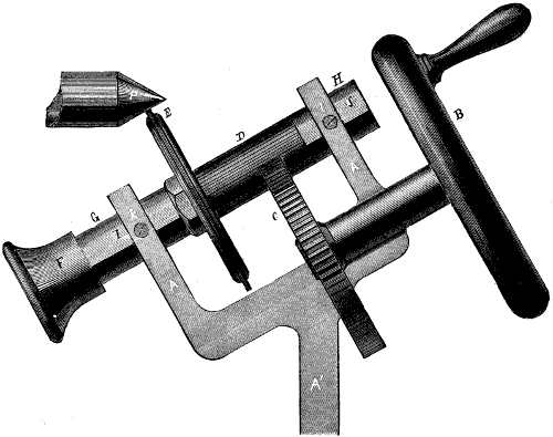
Fig. 1156.
The best way to true lathe centres is with an emery-wheel. In some lathes there are special fixtures for emery grinding, while in others an attachment to go in the tool post is used. Fig. 1156 shows such an attachment.
In the figure a is a frame to be fastened in the slide rest tool post at the stem a′. It affords journal bearing to the hand wheel b, to the shaft of which is attached the gear-wheel c, which drives a pinion d, on a shaft carrying the emery-wheel e, the operation being obviously to rotate wheel b, and drive the emery-wheel e, through the medium of the multiplying gear-wheels c, d.
The emery-wheel is fed to its depth of cut on the lathe centre p, by the cross feed screw of the lathe, and is traversed by pulling or pushing the knob f, the construction of this part of the device being as follows: g and h are two bushes, a sliding fit in the arms of frame a, but having on top flat places i and j, against which touch the ends of the two set-screws k, l, to prevent them from rotating. The emery-wheel and gear pinion d are fast together, and a pin passes through and holds g and h together. Hence the knob f pushes or pulls, as the case may be, the bushes through the bearings g, h, in the frame a, the pinion and emery-wheel traversing with them. Hence pinion d is traversed to and fro by hand, and it is to admit of this traverse that it requires its great length. The stem a is at such an angle that, if it be placed true with the line of cross feed, the lathe centre will be ground to the proper angle.
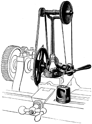
Fig. 1157.
Fig. 1157 represents a centre grinding attachment by Trump Brothers, of Wilmington, Delaware. In this device the emery-wheel is driven by belt power as follows. A driving wheel a is bolted to the lathe face plate, and a stand carries at its top the over-head belt pulleys, and at its base the emery-wheel and spindle. This stand at c sets over the tool post, and is secured by a bar passing through c and through the tool post, whose set-screw therefore holds the stand in position. On the end of the emery-wheel spindle is a feed lever, by means of which the emery-wheel may be fed along the lathe centre. Cup piece b is for enabling wheel a to be readily set true on the lathe face plate, one end of b fitting the hub of a, while the other receives the dead centre which is screwed up so that b will hold a in place, while it is bolted to the lathe face plate, and at the same time will hold it true.
In the absence of a centre grinding attachment, lathe centres may be turned true with a cutting tool, and finished with water applied to the tool so as to leave a bright and true surface. They should not, for the finest of work, be finished by filing, even though the file be a dead smooth one, because the file marks cause undue wear both to the lathe centres and the work centres.
The dead centres should be hardened to a straw color, and the live centre to a blue; the former so as to have sufficient strength to resist the strain, and enough hardness to resist abrasion, and the latter to enable it to be trued up without softening it.
When, after turning them up, the centres are put into their places, the tailstock may be moved up the bed so that the dead centre projects but very little from the tailstock, and is yet close to the live centre, and the lathe should be run at its fastest speed to enable the eye to perceive if the live centre runs true, and whether the dead centre is in line with the live one, and the process repeated so that both centres may be tested.
A more correct test, however, may be made with the centre indicator.
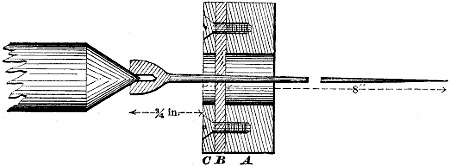
Fig. 1158.
Centre Indicators.—On account of the difficulty of ascertaining when a centre runs quite true, or when a very small hole or fine cone as a centre punch mark runs true when chucked in a lathe, the centre indicator is used to make such tests, its object being to magnify any error, and locate its direction. Fig. 1158, from The American Machinist, represents a simple form of this tool, designed by Mr. G. B. Foote, for testing lathe centres. a is a piece of iron about 8 inches long to fit the lathe tool post, b is a leather disk secured to a by a plate c, and serving to act as a holding fulcrum to the indicator needle, which has freedom of movement on account of the elasticity of the leather washer, and on account of the hole shown to pass through a. It is obvious that if the countersunk end of the needle does not run true, the pointed end will magnify the error by as many times as the distance from the needle point to the leather washer is greater than that from the leather washer to the countersunk end of the needle. It is necessary to make several tests with the indicator, rotating the lathe centre a quarter turn in its socket for each test, so as to prove that the centre runs true in any position in the lathe spindle. If it does not run true the error should be corrected, or the centre and the lathe spindle end may be marked by a centre punch done to show in what position the centre must stand to run true.
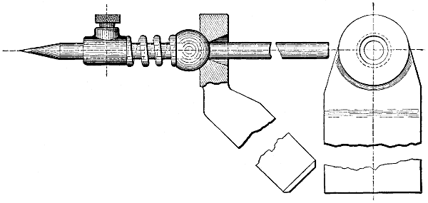
Fig. 1159.
The tension of the leather washer serves to keep the countersunk against the lathe centre without a very minute end adjustment. Or the same end may be attained by the means shown in Fig. 1159, which is a design communicated by Mr. C. E. Simonds to The American Machinist. The holder is cupped on one side to receive a ball as shown, and has a countersink on the other to permit a free vibration of the needle. The ball is fitted to slide easily upon the needle, and between the ball and a fixed collar is a spiral spring that keeps the ball in contact with its seat in the holder.
One end of the needle is pointed for very small holes or conical recesses, while the other is countersunk for pointed work, as lathe centres. The countersink of the needle may be made less acute than the lathe centre, so that the contact will be at the very point of the lathe centre, the needle not being centre-drilled. The end of the needle that is placed against the work should be as near to the ball or fulcrum as convenient, so as to multiply the errors of work truth as much as possible.
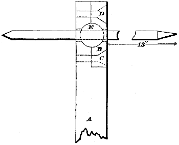
Fig. 1160.
In some forms of centre indicators the ball is pivoted, so that the needle only needs to be removed to reverse it end for end, or for adjusting its distance, it being made a close sliding fit through the ball. Thus, in Fig. 1160 the ball e is held in a bearing cut half in the holder a, and half in cap b, which is screwed to a by screws c d.
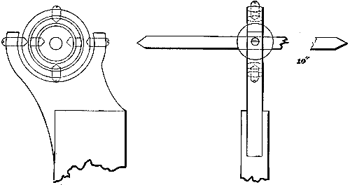
Fig. 1161.
Or the ball may be held in a universal joint, and thus work more frictionless. Thus, in Fig. 1161 it is held by the conical points of two screws diametrically opposite in a ring which is held by the conical points of two screws threading through an outer ring, these latter screws being at a right angle to those in the inner ring. The outer ring is held to the holder by the conical points of two screws, all the conical points seating in conical recesses.
It is obvious that the contact of the point of the needle and the work may be more delicately made when there is some elasticity provided, as is the case with the spiral spring in Fig. 1159.
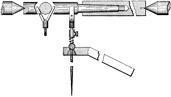
Fig. 1162.
Indicators of this class may be used to test the truth of cylindrical work: thus, in Fig. 1162 is an application to a piece of work between the lathe centres, there being fitted to one end of the needle a fork a that may be removed at pleasure.
One of the difficulties in turning up a lathe centre to run true arises from the difference in cutting speed at the point and at the full diameter of the cone, the speed necessary to produce true smooth work at the point being too fast for the full diameter. This may be remedied on centres for small work, as, say, three inches and less in diameter, by cutting away the back part of the cone, leaving but a short part to be turned up to true the centre.
To permit the cutting off or squaring tool to pass close up to the centre, and thus prevent leaving a burr or projection on the work end, the centre may be thus relieved at the back and have a small parallel relief, as in Fig. 1164 at a, the coned point being left as large as possible, but still small enough to pass within the countersink.
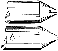
Fig. 1163.
In centres for large and heavy work it is not unusual to provide some kind of an oil way to afford means of lubrication, and an excellent method of accomplishing this object is to drill a hole a, Fig. 1163, to the axis of the centre and let it pass thence to the point as denoted by the dotted line; there may also be a small groove at b in the figure to distribute the oil along the centre, but grooves of this kind make the returning of the centre more difficult and are apt to cause the work centres to enlarge more from wear, especially in turning tapers with the tailstock set over the lathe centre, these being out of line with the work centre.
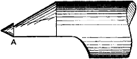
Fig. 1164.
To enable a broad tool such as a chaser to meet work of smaller diameter than the lathe centre, the latter is cut away on one side as in Fig. 1164. It is obvious also that the flat place being turned uppermost, will facilitate the use of the file on work of smaller diameter than the lathe centre, and that placed in the position shown in the cut, it will permit a squaring tool to pass clear down to the centre and avoid leaving the projecting burr which is left when the tool cannot pass clear down the face to the edge of the countersink of the work centre.
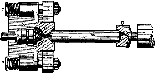
Fig. 1165.
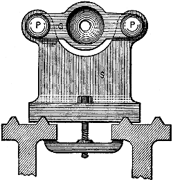
Fig. 1166.
The method to be employed for centring work depends upon its diameter, and upon whether its ends are square or not. When the pieces are cut from a rod or bar in a cutting-off machine, the ends are square, and they may be utilized to set the work by in centring it. Thus, in Fig. 1165 is a top, and in Fig. 1166 is an end view of a simple device, or lathe attachment for centre drilling. s is a stand bolted to the lathe shears and carrying two pins p, which act as guides to the cup chuck or work guide g; between the heads of pins p and the hubs of g are spiral springs, forcing it forward, but permitting it to advance over the drill chuck; the work w is fed forward to the drill. At the dead centre end the work is supported by a female cone centre d in the tail spindle t. The work rests in mouths of g and d, and as the pieces are cut from the rod they are sufficiently straight, and being cut off in a cutting-off machine the ends are presumably square; hence the coned chucks will hold them sufficiently true with the ends, and the alignment of the centre drilled holes will not be impaired by any subsequent straightening processes; for it is to be observed, that if work is centre-drilled and straightened afterwards, the straightening throws the centre holes out of line one with the other, and the work will be more liable to gradually run out of true as its centres wear.
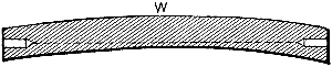
Fig. 1167.

Fig. 1168.
Thus, in Fig. 1167, let w represent a bent piece of work centre-drilled, and the axis of the holes will be in line as denoted by the dotted line, but after the piece is straightened the holes will lie in the planes denoted by the dotted line in Fig. 1168, and there will be a tendency for the work centres to move over towards the sides c d as the wear proceeds.
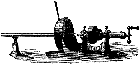
Fig. 1169.
In Fig. 1169 is shown a centre-drilling machine, which consists of a live spindle carrying the centre-drilling tool, and capable of end motion for the drill feed. The work is held in a universal chuck, and if long is supported by a stay as shown in the figure. The axis of the work being in line with that of the chuck, the work requires no setting.
In this case the centre hole will be drilled true with that part of the work that is held in the chuck, and the alignment of the centre hole will depend upon the length of the rod being supported with its axis in line with the live spindle. If the work is not straightened after drilling, the results produced are sufficiently correct for the requirements; but it follows from what has been said, that work which requires to be straightened and tried for straightness in the lathe should be centred temporarily and not centre-drilled until after the straightening has been done.

Fig. 1170.
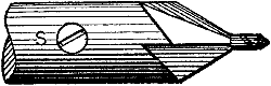
Fig. 1171.
In Fig. 1170 is shown a combined centre-drill and countersink not unfrequently used in centring machines. The objection to it is, that the cutting edges of the drill get dull quicker than those of the countersink, and in regrinding them the drill gets shorter. Of course the drill may be made longer than necessary so as to admit of successive grindings, but this entails drilling the centre holes deeper than necessary, until such time as the drill has worn to its proper length. To overcome this difficulty the countersink may be pierced to receive a drill as in Fig. 1171, the drill being secured by a set-screw s.
Among the devices for centring work by hand, or of pricking the centre preparatory for centre-drilling, are the following:—
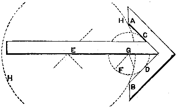
Fig. 1172.
In Fig. 1172 is a centre-marking square. a b c d represents the back and e the blade of the square. Suppose then that the dotted circle f represents the end of a piece of work, and we apply the square as shown in the cut and mark a line on the end of the work, and then moving the square a quarter turn around the work, draw another line, the point of contact of these two lines (as at g in the cut) will be the centre of the work, or if the work is of large diameter as denoted by the circle h h, by a similar process we obtain the centre e. In this case, however, the ends a b of the square back must be of equal lengths, so that the end faces at a b will form a right angle to the edge of the blade, and this enables the use of the square for ordinary purposes as well as for marking centres.

Fig. 1173.
The point a of the centre punch shown in Fig. 1173 is then placed at the intersection of the two lines thus marked, and a hammer blow produces the required indentation. The centre punch must be held upright or it will move laterally while entering the metal. The part b of the centre punch is tapered so as to obstruct the vision as little as possible, while it is made hexagon or octagon at the upper end to afford a better grip. By increasing the diameter at c, the tool is stiffened and is much less liable to fly out of the fingers when the hammer blow does not fall quite fair.
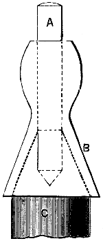
Fig. 1174.
In Fig. 1174 is shown a device for guiding the centre punch true with the axis of the work, so as to avoid the necessity of finding the same by lines for the centres. It consists of a guide piece b and a parallel cylindrical centre punch a, c representing a piece of work. b is pierced above with a parallel hole fitting and guiding the centre punch, and has a conical hole at the lower end to rest on the work, so that if the device be held upright and pressed down upon the end of the work, and the top of the centre punch is struck with the hammer, the indentation made will be central to the points of contact of the end of the work with the coned hole of b. If then the end of the work has no projecting burrs the centring will be centred true.
In the absence of these devices, lines denoting the location for the conical recess or centre may be made, when either of the following methods may be pursued.
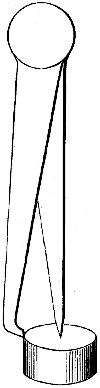
Fig. 1175.
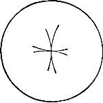
Fig. 1176.
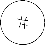
Fig. 1177.
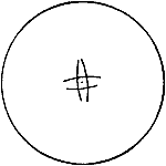
Fig. 1178.
In Fig. 1175 is shown what is known as a pair of hermaphrodite calipers, which consists of two legs pivoted at the upper end; the bent leg is placed against the perimeter of the work, as shown, and held steadily, while with the point a line is marked on the work. This operation is performed from four equidistant (or thereabouts) points on the work, which will appear as shown in Fig. 1176, providing the radius to which the point was set be equal to the radius of the work. The point at which the lines meet is in this case the location for the centre. If, however, the radius to which the points are set is less than the radius of the work, the lines will appear as in Fig. 1177, in which case the location is in the centre of the inscribed square, as denoted by the dot; or if the radius be set too great the lines will appear as in Fig. 1178, and the location for the centre will again be as denoted by the dot.
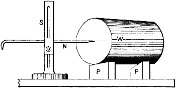
Fig. 1179.

Fig. 1180.
Another and very old method of marking these lines is to place the work on a pair of parallel pieces and draw the lines across it, as shown in Fig. 1179, in which w represents the work, p, p the parallel pieces of equal thickness, s a stand (termed a scribing block) carrying a needle n, which is held by a thumb screw and bolt at b. The point of the needle is adjusted for the centre of the work, a line is drawn, the work is then rotated, another line drawn, and so on, until the four lines are drawn as in Fig. 1180, when the work may be turned end for end if light, or if heavy the scribing block may be moved to the other end of the work.
The centre locations are here made true with the part of the work that rests on the parallel pieces, and this is in some cases an essential element in the centring.

Fig. 1181.
Thus, in Fig. 1181, it is required to centre a piece true with the journals a b, and it is obvious that those journals may be rested on parallel pieces p, p, and the centres marked by the scribing block on the faces e, f in the manner before described.
If there is a spot in the length of a long piece of work where the metal is scant and out of round, so that it is necessary to centre the work true by that part, the surface gauge and parallel pieces may be used with advantage, but for ordinary centring it is a slow process. When a piece of work is not cylindrical, and it is doubtful if it will clean up, the centring requires care, for it must not always be assumed, that if two diametrically opposite points meet the turning tool at an equal depth of cut, the piece is centred so as to true up to the largest possible diameter.
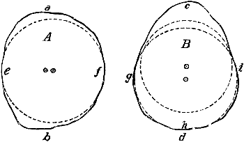
Fig. 1182.
This is pointed out in Fig. 1182, which is extracted from an article by Professor Sweet. “In a piece of the irregular form a, the points a and b might be even and still be no indication of the best location for the centre, and in the piece b it is evident that if c and d were even, nothing like the largest cylinder could be got from it. In the case of shape a, the two points e and f should be equidistant from the centre, and in the case of shape b, the three points g, h, i should be equidistant from the centre.”
The depth of the centre drill holes should be such as to leave them in the work after it is cut off to its proper length, and will, therefore, be deeper as the amount to be cut off is greater.
The diameter of the centre drill is larger as the size of the work increases, and may be stated as about 3⁄64 for work of about 1⁄2 inch, increasing up to 1⁄8 inch for work of about an inch, and up to three inches in diameter; for work of a foot or over the centre drill may be 3⁄16 inch in diameter.

Fig. 1183.
The centre drilling and countersinking may, when the work is cut to length, be performed at one operation, but when it requires to be cut to length in the lathe, that should be done before the countersinking. A very simple chuck for centre drilling is shown in Fig. 1183, with a twist drill (which is an excellent tool for centre-drilling). If the work is held in the hand and fed to the drill by the lathe dead centre, the weight of the work will cause the hole to be out of straight with the work axis, unless the grip is occasionally relaxed, and the work made to rotate a half or a quarter turn as the drilling proceeds.
After the work is centre-drilled and cut off to length, it must be finally countersunk, so as to provide ample bearing area for the lathe centres.
The countersinking should be true to the centre hole; and it is sometimes made to exactly fit the lathe centres, and in other cases it is made more acute than the lathe centre, so that the oil may pass up the countersink, while it is bedding itself to the lathe centres.
If the countersinking is done before the end of the work is squared, it will not be true with the centre-drilled hole.
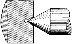
Fig. 1184.
In order that the countersinking may wear true with the centre-drilled hole, it may be made of a more obtuse angle (as, say, one degree) than the lathe centre, as in Fig. 1184, so that the hole may form a guide to cause the lathe centre to wear the countersinking true to the hole, and thus correct any error that may exist.
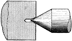
Fig. 1185.
If the countersink is made more acute than the lathe centre, as shown in Fig. 1185, the wear of its mouth will act as a guide, causing the centre to be true with the countersinking; and when the bearing area extends to the centre-drilled hole, there will be introduced, if that hole does not run true, an element tending to cause the work to run out of true again, because the countersinking will have more bearing area on one side than on the other.
It is to be observed, however, that if the difference between the countersink angle and that of the lathe centre be not more than about one degree, the work centre will bed itself fully to the lathe centre very rapidly, and usually before the first cut is carried over the work, unless the work centres have been made to have unduly large countersinks.
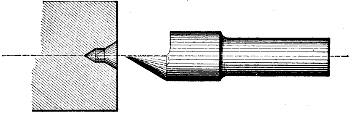
Fig. 1186.
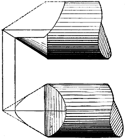
Fig. 1187.
Fig. 1186 represents a half-round countersink, in which the cutting edge is produced by cutting away the coned point slightly below the dotted axial line. This secures two advantages: first, it gives the cutting edge clearance without requiring the grinding or filing such clearance; and, secondly, the cone being the same angle as the lathe centres, filing away more than half of it causes it to give the lathe centre at first a bearing at the small end of the countersink, as in Fig. 1184, and this secures the advantage mentioned with reference to that figure. It is obvious that such a reamer, however, does not produce strictly a cone countersink, as is shown in Fig. 1187, where the cutting away of the cone is carried to excess simply to explain the principle, and the cone becomes an hyperbolic curve.
The small amount, however, that it is necessary to carry the face below the line of centres, practically serves to make the cone somewhat less acute, and is not therefore undesirable.
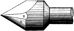
Fig. 1188.
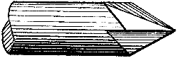
Fig. 1189.
Another method of forming the half-round countersink is shown in Fig. 1188, in which the cone is of the same angle as the lathe centres; the back a is ground away to avoid its contact with the work and give clearance, while clearance to the cutting edge is obtained by filing or grinding a flat surface b at the necessary angle to the upper face of the cone. In this case it is assumed that the centre-drilling and countersinking are true one with the other. Yet another form of countersink is shown in Fig. 1189, consisting of a cone having three or four teeth. It may be provided with a tit, which will serve as a guide to keep the countersink true with the hole, and this tit may be made a trifle larger in diameter than the hole, and given teeth like a reamer, so as to ream the hole out while the countersinking is proceeding.
Unless one side of a half-round reamer is filed away so as to give the cutting edge alone contact with the bore of the hole, an improper strain is produced both upon the work and the countersink.
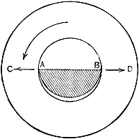
Fig. 1190.
In Fig. 1190, for example, is shown, enlarged for clearness of illustration, a hole, and a half-round countersink in section, and it is evident that if the countersink is set central to the hole, it will have contact at a and at b, and a cannot enter the metal to cut without springing towards c.
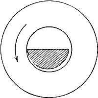
Fig. 1191.
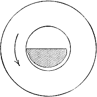
Fig. 1192.
But when the lathe has made rather more than one-half a revolution, the forcible contact at b will be relieved, and either the work or the countersink will move back towards d. This may be remedied by setting the countersink to one side, as in Fig. 1191, or by cutting it away on one side, as in Fig. 1192, when the half-round reamer will, if the work be rigidly held while being countersunk, act as a cutting tool. But it is more troublesome to hold the work rigidly while countersinking it than it is to simply hold it in the hands, and for these reasons the square centre is an excellent tool to produce true countersinking.
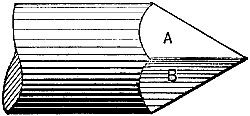
Fig. 1193.
Fig. 1193 represents a square centre, the conical end being provided with four flat sides, two of which appear at a b, or it may have three flat sides which will give it keener cutting edges, and will serve equally well to keep it true with the drilled hole. But it is questionable whether it is not an advantage not to have the cutting edges so keen as is given by the three flat faces, because the less keen the cutting edges are, the more true the countersinking will be with the hole, the extra pressure required to feed the square centre tending to cause it to remain true with the hole notwithstanding any unequal density of the metal on different sides of the hole. An objection to the square centre is that it involves more labor in the grinding to resharpen it, and is not so easy to grind true, but for fine work this is more than compensated for in the better quality of its work.
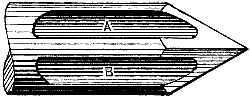
Fig. 1194.
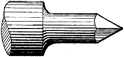
Fig. 1195.
This labor, however, may be lessened in two ways: first, the faces may be fluted, as in Fig. 1194, at a and at b, or its diameter may be turned down, as in Fig. 1195. In using the square centre it is placed in the position of the live centre and revolved at high speed, all the cutting edges operating simultaneously; the work is fed up by the dead centre and held in the hand.
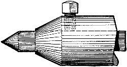
Fig. 1196.
To prevent the weight of the work from causing the countersinking being out of true with the hole, the work should be occasionally allowed (by relaxing the grip upon it) to make part of a revolution, as explained with reference to centre-drilling without a work guide. Another and simple form of square centre for countersinking is shown in Fig. 1196. It consists of a piece of square steel set into a stock or holder.

Fig. 1197.
Work that is to be hardened and whose centres are, therefore, liable to warp in the hardening, may be countersunk as in Fig. 1197, there being three indentations in the countersink as shown. This insures that there shall be three points of contact, and the work will run steadily and true. Furthermore, the indentations form passages for the oil, facilitating the lubrication and preventing wear both to the work and to the lathe centres.

Fig. 1198.
These indentations are produced after the countersinking by the punch, shown in Fig. 1198. Except when tapers are turned by setting the lathe centres out of line with the lathe shears (as in setting the tailstock over), all the wear falls on the dead centre end of the work, as there is no motion of the work centre on the live centre, hence the work centres will not have worn to a full bearing until the work has been reversed end for end in the lathe.
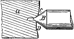
Fig. 1199.
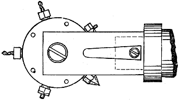
Fig. 1200.
If it be attempted to countersink a piece of work whose end face is not square, the countersinking will not be true with the centre hole, and furthermore the causes producing this want of truth will continue to operate to throw the work out of true while it is being turned. Thus, in Fig. 1199, a represents a piece of work and b the dead centre; if the side c is higher than side d of the work end, the increased bearing area at c will cause the most wear to occur at d, and the countersink in the work will move over towards d, and it follows that the face of a rough piece of work should be faced before being countersunk. Professor Sweet designed the centre-drilling device shown in Fig. 1200, which consists of a stock fitting the holes for the lathe centres, and carrying what may be called a turret head, in which are the centre drills, facing tools, and countersinks. The turret has 6 holes corresponding to the number of tools it carries, and each tool is held in position by a pin, upon a spring, which projects into the necessary hole, the construction being obvious. The facing tool is placed next to the drill and is followed by a countersink, in whatever direction the turret is rotated to bring the next tool into operation. The work should, on account of the power necessary for the facing, be driven in a chuck.
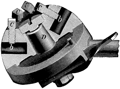
Fig. 1201.
A similar tool, which may, however, be used for other work besides centring and countersinking, is shown in Fig. 1201. It consists of a stem fitting into the hole of the tail spindle, and carrying a base having a pin d, on which fits a cap having holes b, and set-screws c for fastening drills, countersinks, or cutting tools. The cap is pierced with six taper holes, and a pin projects through the base into these holes to lock the cap in position, this pin being operated by the spring lever shown.
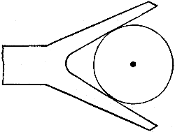
Fig. 1202.
Work that has already been turned, but has had its centres cut off, may be recentred as follows. One end may be held and driven by a chuck, while the other end is held in a steady rest such as was shown in Fig. 802, and the centre may then be formed in the free end by a half-round reamer, such as shown in Fig. 1190, placed in the position of the dead centre, or the square centre may be used in place of the dead centre, being so placed that one of its faces stands vertically, and therefore that two of its edges will operate to cut. The location for the work centre should be centre punched as accurately as possible, and the work is then placed in the lathe with a driver on it, as for turning it up; a crotch, such as shown in Fig. 1202, is then fastened in the lathe tool post, and fed up by the cross-feed screw until it causes the work to run true, and the square centre should then be fed slowly up and into the work, with a liberal supply of oil. If the work runs out of true, the crotch should be fed in again, but care must be taken not to feed it too far. So long as the square centre is altering the position of the centre in the work, it will be found that the feed-wheel of the tailstock will feed by jumps and starts; and after the feeding feels to proceed evenly, the crotch may be withdrawn and the work tried for being true. The crotch, as well as the square centre, should be oiled to prevent its damaging the work surface. It is obvious that in order to prevent the lathe dead centre point from seating at the point or bottom of the work centre, the square centre should be two or three degrees more acute in angle than the lathe dead centre. If the work is tried for truth while running on the square centre, the latter is apt to enlarge the work centre, while the work will not run steadily, hence it is better (and necessary where truth is a requisite) to try the work with the dead centre in place of the square one.
In thus using a square centre to true work, great care should be taken not to cut the work centres too large, and this may be avoided by making the temporary centre-punch centres small, and feeding the crotch rapidly up to the work, until the latter runs true, while the square centre is fed up only sufficiently to just hold the work steady.
To test the truth of a piece of rough work, it may, if sufficiently light, be placed between the lathe centres with a light contact, and rotated by drawing the hand across it, a piece of chalk being held in the right hand sufficiently near to just touch the work, and if the chalk mark extends all round the work, the latter is as true as can be tested by so crude a test, and a more correct test may be made by a tool held in the tool rest. If the test made at various positions in the length of the work shows the work to be bent enough to require straightening, such straightening may be done by a straightening lever.
In shops where large quantities of shafting are produced, there are special straightening tools or devices: thus, Figs. 1203 and 1204 represent two views of a straightening machine. The shaft to be straightened is rotated by the friction caused by its own weight as it lies between rollers, which saves the trouble of placing the shaft upon centres. Furthermore, the belt that is the prime mover of the gears driving these rollers is driven from the line shaft itself without the aid of any belt pulley. The tension of this driving belt is so adjusted that it will just drive the heaviest shaft the machine will straighten; but if the operator grasps the shaft in his hand, the driving mechanism will stop and the belt will slip, the shaft remaining stationary until the operator sets it in motion again with his hand, when the belt ceases to slip and the mechanism again acts to drive the shaft.
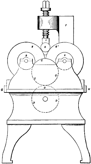
Fig. 1203.
Fig. 1203 represents the mechanism for driving the shaft s, to be straightened, which lies upon and between two rollers, r, r′. Upon the shafts of these rollers are the gear-wheels a and b, which are in gear with wheel c, the latter being driven by gear-wheel d. Motion to d is derived from a pair of gears, the pinion of which is driven by the belt from the line shaft. h is a head carrying all these gears (and the rollers) except d. There are two of these heads, one at each end of the machine, the two wheels d being connected by a rod running between the shears, but the motion is communicated at one end only of this rod, the shaft is driven between four rollers, of which two, r r′, are shown in the engraving.
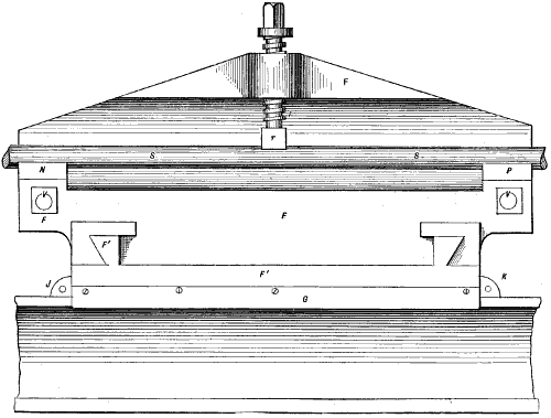
Fig. 1204.
In Fig. 1204 the straightening device is shown. A frame consisting of two parts, f, f′, is gibbed to the edge of the shears at g and h. The upper part of this frame carries a square-threaded screw i, and is capable of sliding across the shears upon the part f′. It rests upon the shears through the medium of four small rollers (which are encased), two of which are at j, k, and two are similarly situated at the back of the frame f′. The motion of f across the machine is provided so that the upper part f may be pushed back out of the way, to permit the shaft being easily put on and taken off the friction rollers r r′. The motion along the shears is provided to enable the straightening device to be moved to the required spot along the shaft s′. The shaft s is laid on two pieces n, p, and a similar piece r is placed above to receive the pressure of the screw i, which is operated by a hand lever to perform the straightening. The pieces n, p rest upon two square taper blocks v, which are provided with circular knobs at their outer ends to enable them to be held and pushed in or pulled out so as to cause n, p to meet the shaft before i is operated. This is necessary to accommodate the different diameters of shaft s. The operator simply marks the rotating shaft with chalk in the usual manner to show where it is out of true, and then straightens wherever it is found necessary.
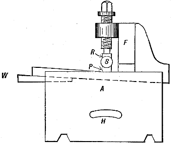
Fig. 1205.
Fig. 1205 represents a similar device for straightening rods or shafts while they are in the lathe. a is a frame or box which is fitted to rest on the Vs of the lathe shears, the straightening frame resting on the box. Instead, however, of simply adjusting the height of the pieces p to suit different diameters of the shaft, the whole frame is adjusted by means of the wedge w, which is inserted between the frame f and the upper surface of the box a. At h is a hole to admit the operator’s hand to move a along the lathe shears.
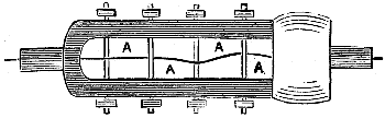
Fig. 1206.
A method of straightening wire or small rods that are too rigid to be straightened by hand, and on which it is inadvisable to use hammer blows, is shown in Fig. 1206. It consists of a head revolved in a suitable machine, and having a hole passing endways through it. In the middle is a slot and through the body pass the pins a, being so located that their perimeters just press the rod or wire when it is straight, and in line with the axis of the bore through the head, each successive pin a touching an opposite side of the wire or rod. It is obvious that these pins in revolving force out any crooks or bent places in the wire or rod, and that as the work may be pulled somewhat rapidly through the head or frame, the operation is a rapid one.
When pieces of lathe work are to be made from rod or bar iron, they should be cut off to the proper length in a cutting-off machine, such as described in special forms of the lathe, and for the reasons set forth in describing that machine.
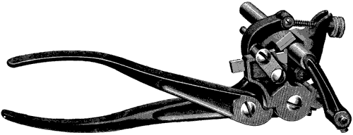
Fig. 1207.
An excellent tool, however, for cutting up rods of not more than 1⁄2 inch in diameter, is Elliott’s cutting-off tool shown in Fig. 1207. It consists of a jaw carrying steadying pieces for the rod to be cut up, these pieces being adjusted to fit the rod by the screw and nut shown. On the same jaw is pivoted a tool-holder, carrying a cutting-off tool, which is fed to its cut by the upper handle being pressed towards the lower one.
An adjustable stop or gauge is attached, by means of a small rod, to the swinging arm which carries the cutting tool, and can be removed when its use is not desirable.
The operation of this tool is as follows:—The rod to be cut up is held in the lathe chuck, projecting beyond any desired distance, and arranged to revolve at the same speed as for turning. The tool is placed upon the rod, and the movable jaw of the rest adjusted to a bearing. If several pieces are to be cut to a length, the gauge is adjusted, the tool moved along the rod till the gauge-stop comes in contact with the end, the handles pressed together, which moves the cutting tool up to the work in such a way that it will come exactly to the centre, thus cutting the piece entirely off, no adjustment of the tool ever being necessary to provide for its cutting to the centre, except keeping the cutting edge (which is not in this respect changed by grinding) at a distance specified in the directions from the part in which it is clamped. As the tool is moved up to cut, by the same operation the gauge is moved back out of contact with the end. When the pressure on the handles is removed, a spring returns the cutting tool to its original position, and also brings the gauge in position for determining the length of the next piece to be cut. The operation is repeated by simply moving the tool along the rod, the cutting up being done with great rapidity and accuracy. It will be noticed that all the appliances for cutting, gauging, &c., being a part of the tool itself, if the rod runs out of truth—in other words, wabbles—it will have no effect on the cutting, the rod to be cut forming the gauge for all the operations required; also that comparatively no time is lost in adjustment between the several pieces to be cut from a rod.
The cutting tool is a piece of steel of the proper thickness, cleared on the sides by concave grinding. It is held in place by a clamp and two small screws, and requires grinding on the end only.
When the work is centred, it should, for reasons already explained, have its end faces trued up.
In doing this, however, it is desirable in some cases to cut off the work to its exact finished length. This possesses the advantage, that when the work is finished, the work centres will be left intact, and the work may be put into the lathe at any time, and it will run true to the original centres. But this is not always the best plan; suppose, for example, that there are a number of collars or flanges on the work, then it is better to leave a little extra length to the work when truing up the ends, so that if any of the collars are scant of metal, or if it be desirable to turn off more on one side of a collar than on another, as may be necessary to turn out a faulty place in the material, the end measurements on the work may be conformed to accommodate this requirement, and not confined to an exact measurement from the end of the work.
Again, in the case of work having a taper part to be fitted, it is very difficult to obtain the exact proper fit and entrance of taper to an exact distance, hence it is best to leave the work a little too long, with its collars too thick, and to then fit the taper properly and adjust all other end measurements to suit the taper after it is fitted.
Before any one part of a piece of work turned between the lathe centres is finished to diameter, all the parts to be turned should be roughed out, and for the following reasons, which apply with additional force to work chucked instead of being turned between the lathe centres.
It is found, that all iron work changes its form if the surface metal be removed from it. Thus, though the lathe centres be true, and a piece of work be turned for half its length in the lathe, after it has been turned end for end in the lathe to turn the other half of its length, the part already turned will run out of true after the second half is turned up. This occurs from the tension and unequal internal strains which exist in the metal from its being forged or rolled at a constantly diminishing temperature, and from the fact that the surface of the metal receives the greatest amount of compression during the forging.
In castings it is caused by the unequal and internal strains set up by the unequal cooling of the casting in the mould, because of one part being thicker than another.
When the whole of the work surfaces have been cut down to nearly the finished size, this alteration will have taken place, and the finishing may be proceeded with, leaving the work as true as possible. In chucked work, or the most of it rather, it is impracticable (from being too troublesome) to rough out all over before finishing; hence at each chucking all the work to be done at that chucking is finished.
The roughing cuts on a piece of work should always be taken with as coarse a feed as possible, because the object is to remove the mass of the metal to be cut away rather than to produce a finish, and this may be most quickly done by a deep cut and coarse feed. Theoretically also the finishing should be done with a coarse feed, since the coarser the feed, the less the length of time the cutting edge is in action. But the length of cutting edge in action, with a given tool and under a given depth of cut, increases as that edge is made longer to carry the coarse feed, and the long cutting edge produces a strain that tends to spring or bend the work, and that causes the tool to dip into seams or soft spots, or into spongy or other places, where the cutting strain is reduced, and also to spring away from hard spots or seams, where the cutting strain is increased. The most desirable rate of feed, therefore, is that which is as coarse as can be used without springing either the work or the tool, and this will depend upon the rigidity of the work of the lathe, and of the cutting tool. Short or slight work may be turned very true by a light cut fine feed and quick cutting speed, but the speed must obviously be slower in proportion as the length of the work increases, because the finishing cut should be taken without taking the tool out to resharpen it, since it is very difficult to set the tool to the exact proper depth a second time.
Since the cutting edge will, at any given rate of cutting speed, retain its keenness better for a given surface of work in proportion as the time it is under duty is diminished, it follows, therefore, that the coarser the feed the better (so long as both the work and the tool are sufficiently rigid to withstand the rate of feed without springing).
Under conditions of rigidity that are sufficiently favorable a tool, such as in Fig. 948, may be used on wrought or cast iron, at a feed of 1⁄2 or even 3⁄4 inch of traverse per lathe revolution, producing true and smooth work, providing that the tool be given a very slight degree of clearance, that its cutting edge is ground quite straight, that it is set parallel to the line of feed, or what is the same thing, to the work axis, and that the length of cutting edge is greater than the amount of tool traverse per lathe revolution, as is shown in the figure, the amount of tool traverse per lathe revolution obviously being from a to b. It may also be observed that the leading corner of the tool may with advantage be very slightly rounded as shown, so that there shall be no pointed corner to dull rapidly.
In proportion as the work is light and the pressure of the cut may spring it, the feed must be lessened, so that on very slender work a feed of 100 lathe revolutions per inch of tool travel may be used. On cast-iron work the feeds may be coarser than for wrought-iron, the other conditions being equal, because cast iron cuts easier and therefore springs the work less for a given depth of cut. But since cast iron is apt to break out, exposing the pores of the metal, and thus leaving small holes plainly visible on the work surface, the finishing cut should be of very small depth, indeed a mere scrape; and if the surface is to be polished, a fine feed and a quick speed will leave a cleaner cut surface, and one that will require the least polishing operations to produce a clean and spotless surface. Brass work also is best finished with a fine feed and a quick speed.
It is obvious that the top face of the tool should be given more rake for wrought iron than for cast iron or steel, and that in the case of the very fine feeds, the form of tool shown in figure is the best for finishing these metals.
In turning a number of pieces requiring to be of the same diameter, it is to be borne in mind that a great part of the time is consumed in accurately setting the tool for the finishing cut, and that if one piece is finished at a time, this operation will require to be done separately for each piece.
It is more expeditious, therefore, to rough all the pieces out, leaving enough metal for a fine finishing cut to be taken, and then finish these pieces without moving the tool; which may be done, after the tool is once set, by letting the tool stand still at the end of the first finishing cut, and taking the work out of the lathe. The carriage is then traversed back to the dead centre, and another piece of work is put in, and it is obvious that as the cross-feed screw is not operated after the tool is once set, the work will all be turned to the same diameter without any further measuring than that necessary for the first piece.
If the tool is traversed back to the dead centre before the lathe is stopped or before the work is removed from the lathe, one of two results is liable to follow. If the lathe is left running, the tool will probably cut a spiral groove on the work, during its back traverse; or if the lathe be stopped, the tool point will mark a line along the work, and the contact of the tool point with the work will dull the cutting edge of the tool. The reason of this is as follows: When the slide rest and carriage are traversing in one direction, the resistance between the tool and the cut causes all the play in the carriage and rest, and all the spring or deflection of those parts, to be in an opposite direction. Now if the play and spring were precisely equal for both directions, the tool should cut to an equal diameter with the carriage traversed in either direction, but the carriage in feeding is fed by the feed nut or friction feed device, while when being traversed back the traversing handle is used; thus the power is applied to the carriage in the two cases at two different points, hence the spring of the parts, whether from lost motion, or play from wear, or from deflection, is variable. Again, even with the tool fed both to its cut and on the back traverse with the hand feed handle, the play is, from the altered direction of resistance of the cut, reversed in direction, and the depth of cut is therefore altered.
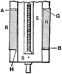
Fig. 1208.
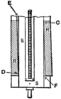
Fig. 1209.
Thus, in Fig. 1208, let s s represent the cross slide on the carriage and r r the cross slide of the tool rest shown in section, and suppose the tool to be traversing towards the live centre, then to whatever amount there may be play or spring between the slide and the slide way, the slide will from the pressure of the cut twist over, bearing against the slide way at a and b, and being clear of it at g and h. On reversing the direction of traverse of the rest, so as to feed the tool towards the dead centre, the exactly opposite condition will set in, that is, the pressure of the cut will force the slides in the opposite direction, or in other words, the contact will be as in Fig. 1209, at c, d, and the play at e, f. During the change of location of bearing between the slides and the way, there will have been a certain amount of tool motion altering the distance of the tool point from the line of centres, and therefore the diameter to which it will cut. The angle at which the body of the tool stands will influence the effect: thus, if when traversing towards the live centre the tool stands at an angle pointing towards the live centre, it would recede and cause the tool to clear the cut, if removed on the back traverse without being moved to or from the line of centres. Conversely, if the body of the tool was at an angle, so that it pointed towards the dead centre, and a cut was taken towards the live centre, and the tool was traversed back without being moved in or out, it would take another cut while being moved back.
The conditions, however, are so uncertain, that it is always advisable to be on the safe side, and either wind the tool out from its cut before winding the rest and carriage back (thus destroying its set for diameter), or else to stop the lathe and remove the work before traversing the carriage back as already directed. If the latter plan is followed the trouble of setting the tool is avoided and much time is saved, while greater accuracy of work diameter is obtained. It is obvious that this plan may be adopted for roughing cuts in cases where two cuts only are to be taken, so as to leave finishing cuts of equal depths; or if three cuts are to be taken, it may advantageously be followed for the second and last cuts, the depth of the first cut being of less importance in this case.
The following rules apply to all tools and metals:
When the pressure between the tool and the work is sufficient, from the proportions of the work, to cause the work to spring or bend, the length of acting cutting edge on the tool should be reduced.
As the diameter and rigidity of the work increases, the length of tool cutting edge may increase. The cutting edge of the tool should be kept as close as the work will conveniently admit to the slide rest tool post, 1⁄4 inch even of this distance being important.
The slide rest tool should always be resharpened to take the finishing cut, with which, for wrought iron or steel, soapy water with soda in it should be used, the soda serving to prevent the dripping water from rusting the parts of the lathe.
Cast iron will cut with an exquisite polish if finished at a very slow rate of cutting speed, and turned with a spring tool, such as was shown in Fig. 974, and water is used. But being a slow process it is not usual to finish it in this manner, though for round corners, curves, &c., this method is highly advantageous.
For cast iron the tool should be as keen as the hardness of the metal of the work will permit. If an insufficiently keen tool, or too deep a cut, or too coarse a feed be taken, the metal will break out instead of cutting clean, and numerous fine holes will be perceived over the whole surface, impairing that dead flatness which is necessary to an even and fine polish.
To remove these specks or holes in cylindrical work, the file may be used, but for radial faces hand-scrapers, such as shown in Fig. 1295, are used, the work rotating in either case at high speed. Such scrapers are oilstoned and held with the handle end above the horizontal level.
The rest should be so conformed to suit the shape of the work, that the scraper will be supported close to the work, which will prevent chattering, and a piece of leather should (as a further preventive of chattering) be placed beneath the scraper. A very good method of using a scraper is to adjust it to the work, and holding it still on the rest, traverse the slide rest to move the scraper to its cut.
After the scraping, three methods of polishing radial faces are commonly employed; the first is to use emery paper only, and the second is by the use first of grain, emery, and oil, and the subsequent use of emery paper or cloth, and the third is by the use of emery wheels and crocus cloth.
If the work is finished by emery paper only, and it requires much application of the same to efface the scraper marks, the evil will be induced that the emery cuts out the metal most where it is most porous, so that the finished surface is composed of minute hills and hollows, and the polish, though bright and free from marks, will not have that dead flat smooth appearance necessary to a really fine polish and finish; indeed, the finish is in this case to some extent sacrificed to obtain the polish.
It is for this reason that stoning the work (as hereafter described) is resorted to, and that grain emery and lead is employed, which is done as follows:—
For a flat radial face, a flat piece of lead, say 3⁄8 inch thick, and of a size to suit the work, may be pivoted to the end of a piece of wood of convenient length and used with grain emery and oil, the work rotating quickly. To afford a fulcrum for the piece of wood, a lever or rest of some kind, as either a hand rest or a piece fastened in the tool post, is used.
The rest should be placed a short distance from the work surface and the lever held partly vertical until the lead meets the work surface, when depressing the lever end will force the lead against the work. The lever end must be quickly moved laterally, so that the lead will approach and then recede from the work centre; this is necessary for two reasons. First, to prevent the emery from cutting rings in the work surface, and secondly, to prevent the formation of grooves behind any hollow spots or specks the work may contain. The reason of the formation of these grooves is that the emery lodges in them and works out from the contact of the lead, so that if on working out they move always in the same line they cut grooves.
When a lathe is provided with belt motion to run both ways, it is an excellent plan to apply the lead with the lathe running forward and then with it running backward.
When by this means the scraper marks are removed, the next object is to let the marks left by the lead be as fine and smooth as possible, for which purpose flour emery should be used; but towards the last no emery, but oil only, should be applied, the lead being kept in constant lateral motion, first quickly and then slowly, so that the marks on the work cross and recross it at different angles.
For round or hollow corners the lead need not be pivoted to the stick, but should be spherical at the end, the marks being made to cross by partly rotating the lever first in one direction and then in the other.
Sometimes the end of the lever is used without the addition of lead, but this does not produce so flat a surface, as it cuts out hollows in the pores of the metal.
For polishing to be done entirely in the lathe, emery paper and crocus may follow the lead, being used dry and kept also in constant lateral motion. Each successive grade of emery paper must entirely remove all marks existing on the work at the time of its (the paper’s) first application, and, furthermore, each successive grade should be continued until it is well worn, because of two pieces of emery paper of the same grade that most worn will cut the smoothest and polish the best. For the final polishing a piece of the finest emery paper should be prepared in the manner hereafter described for polishing plain cylindrical surfaces.
The radial faces of wrought iron must be finished as smoothly and true as possible, because being harder than cast iron the emery acts less rapidly upon it. For radial faces on brass the surfaces should be finished as smooth as possible with the slide rest tool, which should be round nosed, with the round flattened somewhat where the tool cuts, and the tool should not, under any condition, have any rake on its top face, while the feed should be fine as, say, 32 revolutions per inch of tool travel. Under skillful manipulation scraping may then be dispensed with, although it may be used to a slight extent without impairing the truth.
Very small radial surfaces of brass may best be finished by the scraper and polished with emery paper, while large ones may be finished with dry emery paper.
Round corners on brass work should be finished with a spring tool, such as shown in Fig. 974, but having negative top rake; but if the corners are of small radius a well oilstoned hand-scraper is best.
To enable the smooth and true turning of all radial faces of large diameter, the lathe head should, when it is possible, be steadied for end motion by placing a rod between the lathe centres, but if the radial face is solid at the centre so that such a rod cannot be put in, the end motion adjusting device of the lathe should be adjusted. The slides of the lathe should also be set up to have good firm contact, and the tool should be brought up to the work by putting the feed motion in gear and operating it by hand at the cone pulley, or gear-wheel on the feed spindle. If the lathe has no compound rest, the cut should be put on by this means, but otherwise the tool may be brought near the work by the feed motion and the cut put on by the compound rest, the object in both cases being to take up all lost motion and hold the rest firmly or steadily on the lathe shears, so that it shall not move back as the cut proceeds.
Work of cast iron or brass and of small dimensions and irregular or curved outline should be finished with scraping tools, such as shown in Figs. 1303 and 1310, polished with emery cloth or paper. But whenever scrapers are made with curves to suit the form of the work, such tool curves should be so formed (for all metals) as not to cut along the whole length of cutting edge at once, unless the curve be of very small length as, say, 1⁄4 inch. This is necessary, because if the cutting edge operates on too great a length it will jar or chatter.
For convex surfaces the curve on the scraper should be of greater radius than that of the work, while in the case of concave curves the tool should have a less radius. In both cases the tool will require a lateral movement to cause it to operate over the full width of work curve.
If the work curves are sufficiently large, and the same is sufficiently rigid that a slide rest tool may be used, the length of cutting edge may be increased, so that under very favorable conditions of rigidity the tool edge may cut along its whole length without inducing either jarring or chattering, but the best results will always be obtained when with a broad cutting edge the tool is of the spring tool form shown in Fig. 974.
Work of wrought iron or steel of small dimensions and of irregular form, must also be finished by hand tools, such as the graver shown in Figs. 1285 and 1286, and the finishing tool shown in Figs. 1289 and 1292, the shape of the tool varying to suit the shape of the work.
Round corners or sweeps cannot on any kind of work be finished by a file, because the latter is apt to pin and cut scratches in the work.
For the final tool finishing of lathe work of plain cylindrical outline, no tool equals the flat file if it be used under proper conditions, which are, that the work be turned true and smooth with slide rest tools, the marks left by these tools being exceedingly shallow and smooth.
A dead smooth file that has been used enough to wear down the projecting teeth (which would cut scratches) should then be used, the work rotating at as fast a speed as the file teeth will stand without undue wear. The file strokes should be made under a light pressure, which will prevent the cuttings from clogging its teeth, and the cuttings should be cleaned from the file after every few strokes. Under these conditions work of moderate diameter may be turned to the greatest degree of smoothness and truth attainable with steel cutting tools, providing that the work makes several revolutions during each file stroke, and it therefore follows that the file strokes may be more rapid as the diameter of the work decreases, and should be more slow as that diameter increases. Allowing the greatest speed of the filed surface permissible, without too rapid destruction of the file teeth, to be 200 feet per minute, and the slowest speed of file stroke that will prevent the file teeth from being ground away or from becoming pinned (when used on wrought iron) to be one stroke in two seconds, the greatest diameter of work that can be finished by filing under the condition that the work must make more than one rotation per file stroke, is about 25 inches in diameter, running about 30 revolutions per minute. The same diameter and speed may be also taken for cast iron, but brass may be filed under increased speed, rendering it practicable to file it up to a diameter of about 36 inches under the above conditions of work rotation and file stroke speed.
Supposing, however, that from hardness of the metal or from its increased diameter the work cannot make a rotation per file stroke unless that stroke be more slowly performed, then the cuttings gather in the teeth of the file, become locked and form projections, termed pins, above the file teeth, and these projections cut scratches in the work, and this it is that renders it impracticable to hold the file still while the work rotates. But suppose the file be applied to work of such a diameter that, with a stroke in two seconds and the work surface rotating at 200 feet per minute, each stroke acts on a fraction of the circumference only, then there can be no assurance that the filed surface will be cylindrical, because there is no means of applying the file equally over the whole surface. But it is to be noted, nevertheless, that the file acts with greater effect in proportion as the area filed is decreased, and that as the tool marks are filed out the area of surface operated upon is increased. Suppose, then, that starting from any point on the work circumference a file stroke be taken, and that it extends around one-third of the circumference, that the second file stroke extends around one-third also, but that there is an unfiled space of, say, two inches between the area of surface filed by these two strokes, and that at the third file stroke the file starts on the surface filed at the first stroke, passes over the two inches previously unfiled and terminates on the surface filed by the second stroke; then the conditions will be as follows:—
Part of the surface filed at the first stroke will have been filed twice, part of the surface filed at the second stroke will also have been filed twice, while the two inches will have been filed once only. But this latter part will have had much more taken off it during the third stroke than did the rest of the surface filed at that stroke, because it operated on the ridges or tool marks where, being unfiled, their area in contact with the file teeth was at a minimum. This condition will prevail until the tool marks are effaced, and tends to preserve the truth of the work up to that point, hence the necessity of leaving very fine tool marks becomes obvious.
Apart from these considerations, however, there is the fact that filing work in the lathe is a very slow operation, and therefore inapplicable to large work; and furthermore, on large work the surface is not needed to be so smooth as in small work; for example, tool feed marks 1⁄1000 inch deep would upon work of 1⁄2 inch diameter leave a surface appearing very uneven, and the wearing away of those ridges or marks would destroy the fit of the piece; but in a piece, say, six feet in diameter, tool marks of that depth would not appear to much disadvantage, and their wearing away would have but little effect upon the fit of the piece.
Finishing with the file, therefore, is usually applied to work of about 24 inches in diameter, and less, larger work being finished with the cutting tool or by emery grinding, where a greater degree of finish is required.
Small work—as, say, of six inches, or less, in diameter—may be finished with the file so cylindrically true, that no error can be discovered by measurement with measuring tools of the calipering class, though the marks of contact if made apparent by gently forcing the work through a closely fitting ring-gauge may not appear to entirely cover the surface.
To produce filed work thus true, all that is necessary is to set the cutting edge of the finishing tool at the horizontal centre of the work, properly adjust the live spindle of the lathe for fit to its bearings, adjust the slides of the slide rest so that there is no lost motion, and follow the rules already given with reference to the shape of the tool cutting edge, employing a cutting speed not so fast as to dull the tool before it has finished its cut, using a fine feed except in the case of cast iron, as already explained.
The requirement that the tool shall not become dull before it has finished its cut, brings us to the fact that the length of work that can be thus accurately turned is limited, as the diameter of the work increases.
Indeed, the length of the work in proportion to its diameter is a very important element. Thus, it would be very difficult indeed to turn up a spindle of an inch in diameter and, say, 14 feet long, and finish it cylindrically true, parallel, and smooth, because
1st. The slightness of the work would cause it to spring or deflect from the pressure or strain due to the cut. This may to some extent be remedied by steadying the work in a follower rest, but the bore of such follower itself wears as the cut proceeds, though the amount may be so small as to be almost inappreciable.
2nd. The work being better supported (by the lathe centres) at the two ends than in the middle of its length, the duty placed on the follower rest will increase as the middle of the work length is approached, hence the spring or deflection of the follower rest will be a disturbing element.
3rd. The tool gets duller as the cut proceeds, causing more strain from the cut, and, therefore, placing more strain on the follower rest; and,
4th. It would be necessary, on account of the length of the cut, to resharpen the tool before the cut was carried from end to end of the spindle, and it would be almost impracticable to set the reground tool to cut to the exact diameter.
The second, third, and fourth of the above reasons operate together in causing increased work spring as the tool approaches the middle of the work length; thus the deflection of the follower rest, the increased weakness of the work, and the comparative dullness of the tool would all operate to cause the work to gradually increase in diameter as the cut proceeded towards the work centre (of length).
Suppose, for example, a cut to have been carried from the dead centre, say, five feet along the work; at the end of this five feet the tool will be at its dullest, the shaft at its weakest, and supported the least from the dead centre and follower rest.
Suppose, then, that the reground tool be placed in the rest again and set to just meet the turned surface without cutting it, then when it meets the cut to carry it farther along the work the cut will produce (on account of the tool being sharper) less strain on the work, which will therefore spring or deflect less. Precisely what effect this may have upon the diameter to which the tool will turn the work will depend upon various conditions: thus, if the top face of the tool be sufficiently keen to cause the strain due to bending the shaving cut or chip to pull the work forward, the tool would turn to a smaller diameter. If the depth of the cut be sufficient to cause the work to endeavor to lift, and the tool edge be above the centre of the work, it would be cut to smaller diameter. If the tool cutting edge were below the centre, or if its top face be at an angle tending to force the work away from the tool point, the diameter of the work would be increased.
From these considerations it is obvious that the finishing cut should be started at the centre of the work length, and carried towards the lathe centres, because in this case the tool will be sharpest, and therefore will produce less tensional strain on the work at the point where the latter is the weakest, while the resisting strength of the work would increase as the cut proceeded, and the tool became dull from use. Furthermore, if it were necessary to regrind the tool, it would be reset nearer to the lathe centres, where the work would be more rigidly held; hence the tool could be more accurately set to the diameter of the finishing cut.
By following this plan, however, it becomes necessary to have the shaft as near true and parallel as possible before taking the finishing cut, for the following reasons:—
Let the diameter of the spindle before the finishing cut be 11⁄32 inches, leaving 1⁄32 inch to be taken off at the finishing cut, then the ring in the follower rest must be at starting that cut 11⁄32 inch bore, and if the rest is to follow the cut the bush must be changed (so soon as it meets the finishing cut) to one of an inch bore. But if the spindle be turned as true and parallel as possible before the finishing cut the rest may lead the tool, in which case the bush need not be changed. There are differences of opinion as to the desirability of either changing the bush or letting the tool follow the rest, but there can be no dispute that (from the considerations already given) a spindle turned as true and parallel as may be with the tool started from the dead centre and carried forward can be improved by carrying yet another cut from the middle towards the dead centre. In any event, however, work liable to spring or too long to be finished at one cut without removing the tool to grind it, can be more accurately finished by grinding in a lathe, such as was shown in Figs. 676 or 679, than by steel-cutting tools, and for the following reasons:—
If it be attempted with steel tools to take a very fine cut, as, say, one of sufficient depth to reduce a diameter, say 1⁄500 inch, the tool is apt to turn an uneven surface. There appears, indeed, to be a necessity to have the cut produce sufficient strain to bring the bearing surfaces of the rest into close contact and to place a slight strain on the tool, because under very light cuts, such as named above, the tool will generally momentarily leave the cut or take a reduced cut, and subsequently an increased one.
It may be accepted that from these causes a finishing cut taken with a steel tool should not be less than that sufficient to reduce the diameter of the work 1⁄64 inch. Now an emery-wheel will take a cut whose fineness is simply limited by the wear of the wheel in the length of the cut. Some experiments made by Messrs. J. Morton Poole and Sons, of Wilmington, Delaware, upon this subject led to the conclusion that with corundum wheels of the best quality the cut could be made so fine that a 12-inch wheel used upon a piece of work (a calender roll) 16 inches in diameter and 6 feet long, would require about forty thousand traverses to reduce the diameter of the work an inch, leading to the conclusion that the wear of the wheel diameter was less than one eighty-thousandth part of an inch per traverse.
Now the strain placed upon the work of an emery-wheel taking a cut of, say, 1⁄1000 inch, is infinitely less than that caused by a cutting tool taking a cut of 1⁄120 inch in diameter; hence the accuracy of grinding consists as much in the small amount of strain and, therefore, of deflection it places upon the work, as upon the endurance of the wheel itself.
Since both in finishing and in polishing a piece of work the object is to obtain as true and smooth a surface as possible, the processes are to a certain extent similar, but there is this difference between the two: where polishing alone is to be done, the truth of the work or refined truth in its cylindrical form or parallelism may be made subservient to the convenience of polish. Thus, in the case of the stem of the connecting rod that has been turned and filed and finished as true as possible, the polishing processes may be continued with emery-cloth, &c., producing the finest of polish without impairing the quality of the work, whereas the degree of error in straightness or parallelism induced by the polishing may impair the degree of truth desirable for a piston rod.
The degree of finish or polish for any piece of work is, therefore, governed to some extent by the nature of its use. Thus a piston rod may be finished and polished to the maximum degree consistent with maintaining its parallelism and truth, while a connecting rod stem may be polished to any required attainable degree.
In finishing for truth, as in the case of journal bearings, the work, being turned as true and smooth as possible, may be filed with the finest of cut files, and polished with a fine grade of emery-cloth or paper; the amount of metal removed by filing and polishing being so small as not to impair to any practically important degree the truth of the work: a journal so finished will be as true as it is possible to make it without the use of a grinding lathe.
Instead of using emery-paper, grain emery and oil may be used, but the work will not be so true, because in this case much more metal will be removed from the work in the finishing or polishing process.
Fig. 1210.
When it is required to polish and to keep the work as true and parallel as possible, these ends may be simultaneously obtained by means of clamps, such as shown in Fig. 1210, which represents a form of grinding and polishing clamp used by the Pratt and Whitney Company for grinding their standard cylindrical gauges. A cast-iron cylindrical body a is split partly through at b and entirely through at c, being closed by the screw d to take up the wear. The split b not only weakens the body a and enables its easy closure, but it affords ingress to the grinding material. It may be noted that cast iron is the best metal that can be used for this purpose, not only on account of the dead smooth surface it will take, but also because its porosity enables it to carry the oil better than a closer grained metal. For work of larger diameter, as, say, 2 or 3 inches, the form of lap shown in Fig. 1211 is used for external grinding, there being a hinge b c instead of a split, and handles are added to permit the holding and moving of the lap. The bore of this clamp is sometimes recessed and filled with lead. It is then reamed out to fit the work and used with emery and oil, the lathe running at about 300 feet per minute.