Volume 1 — Chapter VII.—DETAILS IN LATHE CONSTRUCTION.
Reading edition
Although in each class of lathe the requirements may be practically the same, yet there is a variety of different details of construction by means of which these requirements may be met or filled, and it may be profitable to enter somewhat into these requirements and the different constructions generally employed to meet them.
The cone spindle or live spindle of a lathe should be a close working fit to its boxes or bearings, so that it will not lift under a heavy cut, or lift and fall under a cut of varying pressure. This lifting and falling may occur even though the work be true, and the cut therefore of even depth all around the work, because of hard seams or spots in the metal.
It is obvious that the bearings should form a guide, compelling the live spindle to revolve in a true circle and in a fixed plane, the axis of revolution being in line with the centre line of the tail spindle and that means should be provided to maintain this alignment while preserving the fit, or in other words taking up the wear. The spindle journals must, to produce truly cylindrical work, be cylindrically true, or otherwise the axis of its revolution will change as it revolves, and this change will be communicated through the live centre to the work, or through the chuck plate to the work, as the case may be.
The construction of the bearings should be such, that end motion to the spindle is prevented in as short a length of the spindle as possible, the thrust in either direction being resisted by the mechanism contained in one bearing.
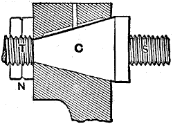
Fig. 553.
In Fig. 553 is a form of construction for the front bearing (as that nearest to the live centre is called), in which end motion to the spindle is prevented at the same time as the diametral fit is adjusted. The spindle is provided with a cone at c and is threaded at t to receive two nuts n which draw the spindle cone within the bearing. In this case the journal at the back end may be made parallel, so that if the spindle either expands or contracts more under variations of temperature than the frame or head carrying the bearings or bearing boxes, it will not bind endwise, nor will the fit be impaired save inasmuch as there may be an inequality of expansion in the length of the front journal and its box. In this case, however, the end pressure caused by holding the work between the lathe centres acts to force the spindle into its bearing and increase the tightness of its fit, hence it is not unusual to provide at the back bearing additional means to resist the thrust of the dead centre.
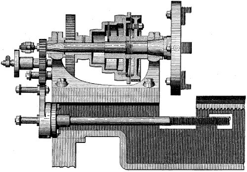
Fig. 554.
Fig. 554, which is taken from “Mechanics,” represents Wohlemberg’s patent lathe spindle, in which both journals are coned, fitting into bushes which can be replaced by new ones when worn; the end thrust is here taken by a steel screw, while the end fit is adjusted by means of a ring nut which binds the face of the large cone gear against the inside face of the front bearing and by the face of the gear that drives the change gears. It may be pointed out, however, that in this construction the spindle must be drawn within to adjust the fit of the front bearing, which can only be done by adjusting the pinion that drives the change gears, or by screwing up the nut that is inside the cone, and therefore cannot be got at. The back bearing can be adjusted by means of the ring nuts provided at each of its ends.
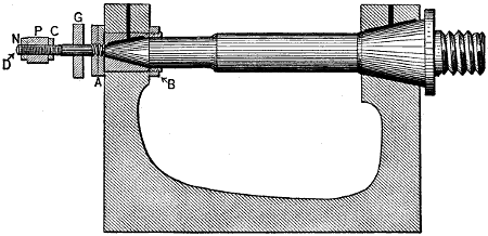
Fig. 555.
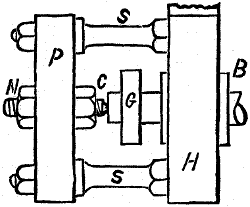
Fig. 556.
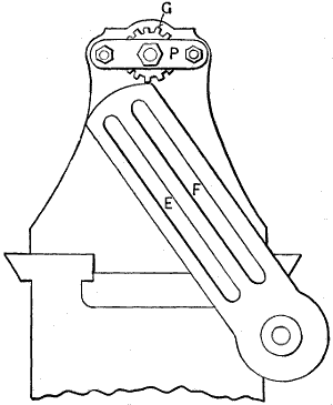
Fig. 557.
Fig. 555 represents another design of cone bearing, in which the spindle is threaded to receive the nuts a which draw it within the front bearing and thus adjust the fit, and at the same time prevent end motion. The back bearing is provided with a bush parallel outside, and furnished with a nut at b to adjust the fit of the end bearing. To prevent the end pressure of the dead centre from forcing the spindle cones too tightly within their bearings a cross piece p is employed (being supported by two studs provided in the head), and through p passes an adjusting screw d, having nuts n and c, one on each side of p. Between the end of d and of the lathe spindle a washer of leather or of raw hide is placed to prevent the end faces from abrading. A similar device for taking up the end thrust is often provided to lathes in which the journals are both parallel, fitting in ordinary boxes, a top view of the device being illustrated in Fig. 556, in which b is the back bearing box, s s two studs supporting cross-piece p, and n and c are adjusting nuts. g is the gear for driving the change wheels for screw cutting or for ordinary feeding as the case may be. In this design the gear wheel g remains fixed and the combinations of gears necessary to cut various pitches of thread must be made on the lead screw and on the swing frame, which must be long enough to permit the change gear stud to pass up to permit the smallest change wheel to gear with wheel g, and which is provided with two grooves e and f, Fig. 557, for two studs to carry two compounded pairs of change wheels. This compounding in two places on the swing frame enables gear g to be comparatively large, and thus saves the teeth from rapid wear, while it facilitates the cutting of left-hand threads, because it affords more convenience for putting in a gear to change the direction of feed screw revolution.
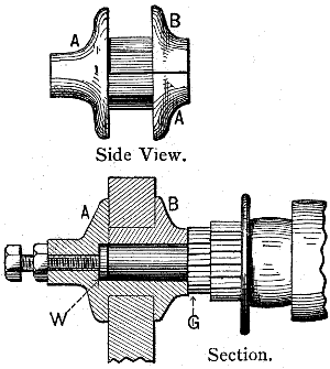
Fig. 558.
In many lathes of American design the journals are made parallel, and the end play is taken up at the back bearing, an example being given in Fig. 558, in which the back bearing boxes are made in two halves a and b, the latter having a set screw (with check nut) threaded through it and bearing against a washer that meets the end of the spindle.
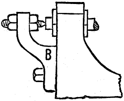
Fig. 559.
A simple method of preventing end motion is shown in Fig. 559, a bracket b affording a support for a threaded adjusting screw, which is sometimes made pointed and at others flat. When pointed it acts to support the spindle, but on the other hand it also acts to prevent the journal from bedding fairly in the boxes. In some cases of small lathes the back bearing is dispensed with, and a similar pointed adjusting screw takes its place, which answers very well for very small work.
Since the strain of the cut carried by the cutting tool falls mainly upon the live centre end of the cone spindle, it is obvious that the bearing at that end has a greater tendency to wear.
In addition to this the weight of the cone itself is greatest at that end, and furthermore the weight of the face plate or chuck, and of the work, is carried mainly at that end. If, however, one journal and bearing wears more than the other, the spindle is thrown out of line with the lathe shears, and with the tail block spindle. The usual method of obviating this as far as possible is to give that end a larger journal-bearing area.
The direction in which this wear will take place depends in a great measure upon the kind of work done in the lathe; thus in a lathe running slowly and doing heavy work carried by chucks, or on the face plate, the wear would be downwards and towards the operator, the weight of the chuck, &c., causing the downward, and the resistance or work-lifting tendency of the cut causing the lateral wear. As a general rule the wear will be least in a lateral direction towards the back of the lathe, but the direction of wear is so variable that provision for its special prevention or adjustment is not usually made. In the S. W. Putnam lathe, provision is made that the bearing boxes may be rotated in the head, so that when the lathe is used on a class of work that caused the live spindle to wear the bearing boxes on one side more than on another, the boxes may be periodically partly rotated in the head so that further wear will correct the evil.
The coned hole to receive the live centre should run quite true, so that the live centre will run true without requiring, when inserted, to be placed in exactly the same position it occupied when being turned up at its conical point. But when this hole does not run true a centre punch dot is made on the end of the spindle, and another on the centre, so that by placing the two dots to coincide at all times, the centre will run true.
The taper given to lathe centres varies from 9⁄16 per foot to 1 inch per foot. In the practice of Pratt and Whitney a taper of 9⁄16 per foot is given to all lathes, the lengths of the tapers for different sizes of lathes being as follows:
Swing of Lathe. Length of Taper Socket for Live Centre.
13 inches 5 inches.
16 „ 3 3⁄4 „
18 and 19 inches 7 11⁄16 „
„ „ with hollow spindle 5 inches long
and 11⁄16 diameter at the small end.
The less the amount of taper the more firmly the centre is held, but the more difficult it becomes to remove the centre when necessary.
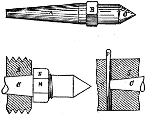
Fig. 560.
The principal methods of removing live centres are shown in Fig. 560, in which is shown at b a square part to receive a wrench, it being found that if not less than about 1⁄2-inch taper per foot of length be given to the live spindle socket, then revolving the centre with a wrench will cause it to release itself, enabling it to be removed by hand. Another method employed on small lathes is to drill a hole through the live spindle to receive a taper pin p, the live centre end being shown at c.
Another and excellent plan for large lathes, is to thread the centre and provide it with a nut m, which on being screwed against the end face of the live spindle will release the centre. The objection to the use of the pin p is that it is apt to become mislaid, and it is not advisable to use a hammer about the parts of the lathe, especially in such an awkward place as between the journal bearing and the cone, which is where the pin hole requires to be located. The square section is, therefore, the best method for small lathes, and the nut for large ones.
In cases where the live spindle is made hollow a bar may be passed through from the rear end to remove the centre; this also enables rods of iron to be passed through the spindle, leaving the end projecting through the chuck for any length necessary for the work to be turned out of its exposed end.
The dead centre may be extracted from the tail spindle by a pin and hole as in Fig. 560, or, what is better, by contact with the end of the tail screw as described when referring to the tail stock of the S. W. Putnam lathe.
The cone pulley should be perfectly balanced, otherwise at high speeds the lathe will shake or tremble from the unbalanced centrifugal motion, and the tremors will be produced to some extent on the work. The steps of the cone should be amply wide, so that it may have sufficient power, without overstraining the belt, to drive the heaviest cut the lathe is supposed to take without the aid of the back gear.
In some cases, as in spinning lathes, the order of the steps is reversed, the smallest step of the cone being nearest to the live centre, the object being to have the largest step on the left, and therefore more out of the way.
The steps of the cone should be so proportioned that the belt will shift from one to the other, and have the same degree of tension, while at the same time they should give a uniform graduation or variation of speed throughout, whether the lathe runs in single gear or with the back gear in. This is not usually quite the case although the graduation is sufficiently accurate for practical purposes. The variation in the diameter of the steps of a lathe cone varies from an inch for lathes of about 12-inch swing, up to 2 inches for lathes of about 30-inch swing, and 3 inches for lathes of 5 or more feet of swing.
To enable the graduation of speed of the cone to be uniform throughout, while the tension of the belt is maintained the same on whatever step the cone may be, the graduation of the steps may be varied, and this graduation may be so proportioned as to answer all practical purposes if the overhead or countershaft cone and that on the lathe are alike.
The following on this subject is from the pen of Professor D. E. Klein, of Yale College.
“The numbers given in the following tables are the differences between the diameters of the adjacent steps on either cone pulley, and are accurate within half a hundredth of an inch, which is a degree of accuracy sufficient for practical purposes.
By simply omitting a step at each end of the cone, the two tables given will be found equally well adapted for determining the diameters of cones having four and three steps respectively.
The following are examples in the use of the tables. Suppose the centres of a pair of pulley shafts to be 60 inches apart, and that the difference of diameter between the adjacent steps is to be as near to 21⁄2 inches as can be, to obtain a uniformity of speed graduation and belt tension, also that each cone is to have six steps, the smallest of which is to be of five inches diameter.
I.—TABLE FOR FINDING CONE PULLEY DIAMETERS WHEN THE TWO PULLEYS ARE CONNECTED BY AN OPEN BELT, AND ARE EXACTLY ALIKE.
The numbers given in table are the differences between the diameters of the adjacent steps on either cone pulley, and can be employed when there are either six or four steps on a cone. When there are six steps, the largest is the first, and the smallest the sixth step of the table. When there are four steps, the largest is the second, and the smallest the fifth step of the table.
Average difference between the adjacent steps. Adjacent steps, whose difference is given in table. Distance between the Centres of Cone Pulleys.
10 inches. 20 inches. 30 inches. 40 inches. 50 inches. 60 inches. 70 inches. 80 inches. 90 inches. 100 inches. 120 inches. 240 inches.
1 inch 1st and 2nd 0.87 0.94 0.96 0.97 0.98 0.98 0.98 0.98 0.99 0.99 0.99 1.00
2nd „ 3rd 0.94 0.97 0.98 0.98 0.99 0.99 0.99 0.99 0.99 0.99 1.00 1.00
3rd „ 4th 1.00 1.00 1.00 1.00 1.00 1.00 1.00 1.00 1.00 1.00 1.00 1.00
4th „ 5th 1.06 1.03 1.02 1.02 1.01 1.01 1.01 1.01 1.01 1.01 1.00 1.00
5th „ 6th 1.13 1.06 1.04 1.03 1.02 1.02 1.02 1.02 1.01 1.01 1.01 1.00
11⁄2 inch 1st and 2nd 1.21 1.36 1.40 1.43 1.44 1.45 1.46 1.46 1.47 1.47 1.48 1.49
2nd „ 3rd 1.36 1.43 1.45 1.46 1.47 1.48 1.48 1.48 1.49 1.49 1.49 1.49
3rd „ 4th 1.50 1.50 1.50 1.50 1.50 1.50 1.50 1.50 1.50 1.50 1.50 1.50
4th „ 5th 1.64 1.57 1.55 1.54 1.53 1.52 1.52 1.52 1.51 1.51 1.51 1.51
5th „ 6th 1.79 1.64 1.60 1.57 1.56 1.55 1.54 1.54 1.53 1.53 1.52 1.51
2 inches 1st and 2nd 1.47 1.74 1.83 1.87 1.90 1.92 1.93 1.93 1.94 1.95 1.96 1.98
2nd „ 3rd 1.74 1.87 1.92 1.93 1.95 1.96 1.96 1.97 1.97 1.97 1.98 1.99
3rd „ 4th 2.00 2.00 2.00 2.00 2.00 2.00 2.00 2.00 2.00 2.00 2.00 2.00
4th „ 5th 2.26 2.13 2.08 2.07 2.05 2.04 2.04 2.03 2.03 2.03 2.02 2.01
5th „ 6th 2.53 2.26 2.17 2.13 2.10 2.08 2.07 2.07 2.06 2.05 2.04 2.02
21⁄2 inches 1st and 2nd 1.66 2.10 2.23 2.30 2.34 2.37 2.39 2.40 2.41 2.42 2.43 2.47
2nd „ 3rd 2.10 2.30 2.37 2.40 2.42 2.43 2.44 2.45 2.46 2.46 2.47 2.49
3rd „ 4th 2.50 2.50 2.50 2.50 2.50 2.50 2.50 2.50 2.50 2.50 2.50 2.50
4th „ 5th 2.90 2.70 2.63 2.60 2.58 2.57 2.56 2.55 2.54 2.54 2.53 2.51
5th „ 6th 3.34 2.90 2.77 2.70 2.66 2.63 2.61 2.60 2.59 2.58 2.57 2.53
3 inches 1st and 2nd 1.76 2.42 2.62 2.71 2.77 2.81 2.84 2.86 2.87 2.88 2.90 2.95
2nd „ 3rd 2.42 2.71 2.81 2.86 2.88 2.90 2.92 2.93 2.94 2.94 2.95 2.98
3rd „ 4th 3.00 3.00 3.00 3.00 3.00 3.00 3.00 3.00 3.00 3.00 3.00 3.00
4th „ 5th 3.58 3.29 3.19 3.14 3.12 3.10 3.08 3.07 3.06 2.06 3.05 3.02
5th „ 6th 4.24 3.58 3.38 3.29 3.23 3.19 3.16 3.14 3.13 3.12 3.10 3.05
4 inches 1st and 2nd 3.95 3.31 3.49 3.59 3.66 3.71 3.75 3.78 3.80 3.83 3.91
2nd „ 3rd 2.94 3.49 3.66 3.75 3.80 3.83 3.85 3.87 3.88 3.89 3.91 3.96
3rd „ 4th 4.00 4.00 4.00 4.00 4.00 4.00 4.00 4.00 4.00 4.00 4.00 4.00
4th „ 5th 5.06 4.51 4.34 4.25 4.20 4.17 4.15 4.13 4.12 4.11 4.09 4.04
5th „ 6th 5.05 4.69 4.51 4.41 4.34 4.29 4.25 4.22 4.20 4.17 4.09
5 inches 1st and 2nd 3.33 3.92 4.20 4.36 4.47 4.55 4.60 4.64 4.68 4.74 4.87
2nd „ 3rd 3.31 4.19 4.47 4.60 4.68 4.74 4.77 4.80 4.82 4.84 4.86 4.93
3rd „ 4th 5.00 5.00 5.00 5.00 5.00 5.00 5.00 5.00 5.00 5.00 5.00 5.00
4th „ 5th 6.69 5.81 5.53 5.40 5.32 5.26 5.23 5.20 5.18 5.16 5.14 5.07
5th „ 6th 6.67 6.09 5.80 5.64 5.53 5.45 5.40 5.36 5.32 5.26 5.13
6 inches 1st and 2nd 3.52 4.42 4.83 5.08 5.23 5.34 5.42 5.49 5.55 5.62 5.80
2nd „ 3rd 4.83 5.23 5.42 5.54 5.62 5.67 5.71 5.75 5.77 5.81 5.90
3rd „ 4th 6.00 6.00 6.00 6.00 6.00 6.00 6.00 6.00 6.00 6.00 6.00
4th „ 5th 7.17 6.77 6.58 6.46 6.38 6.33 6.29 6.25 6.23 6.19 6.10
5th „ 6th 8.48 7.58 7.17 6.92 6.77 6.66 6.58 6.51 6.45 6.38 6.20
To find the diameters for the remaining steps, we look in Table I. (corresponding to cone pulleys with six steps), under 60 in. and opposite 21⁄2 in. and obtain the differences,
2.37 2.43 2.50 2.57 2.63
Each of these differences is subtracted from the larger diameter of the two adjacent steps to which it corresponds, thus:
17.50 = 1st step.
Difference of 1st and 2nd = 2.37
15.13 = 2nd „
„ 2nd „ 3rd = 2.43
12.70 = 3rd „
„ 3rd „ 4th = 2.50
10.20 = 4th „
„ 4th „ 5th = 2.57
7.63 = 5th „
„ 5th „ 6th = 2.63
5.00 = 6th „
Example 2. If we suppose the same conditions as in Example 1, with the exception that each cone is to have four steps instead of six, the largest diameter will, in this case, equal 121⁄2 in. and we may obtain the remaining diameters by omitting the end differences of the above example, and then subtracting the remaining differences as follows:
12.50 = 2nd step.
Difference of 2nd and 3rd = 2.43
10.07 = 3rd „
„ 3rd „ 4th = 2.50
7.57 = 4th „
„ 4th „ 5th = 2.57
5.00 = 5th „
The 2nd, 3rd, 4th, and 5th steps of the table correspond respectively to the 1st, 2nd, 3rd, and 4th steps of the cone, having but four steps. If the smallest diameter had not been assumed equal to 5 in. we might have dropped a step at each end of the six-step cone of the preceding example, and employed the remaining four diameters, 15.13 in. 12.70 in. 10.20 in. and 7.63 in. for one four-step cone.
The present and the previous examples show that we can assume the size of the smallest step anything that we please, and, other things being equal, can make the required cones large or small.
II.—TABLE FOR FINDING CONE PULLEY DIAMETERS WHEN THE TWO PULLEYS ARE CONNECTED BY AN OPEN BELT, AND ARE EXACTLY ALIKE.
The numbers given in table are the differences between the diameters of the adjacent steps on either cone pulley, and can be employed when there are either five or three steps on a cone.
Average difference between the adjacent steps. Adjacent steps, whose difference is given in table. Distance between the Centres of Cone Pulleys.
10 inches. 20 inches. 30 inches. 40 inches. 50 inches. 60 inches. 70 inches. 80 inches. 90 inches. 100 inches. 120 inches. 240 inches.
1 inch 1st and 2nd 0.90 0.95 0.97 0.98 0.98 0.98 0.99 0.99 0.99 0.99 0.99 1.00
2nd „ 3rd 0.97 0.98 0.99 0.99 0.99 0.99 0.99 1.00 1.00 1.00 1.00 1.00
3rd „ 4th 1.03 1.02 1.01 1.01 1.01 1.01 1.01 1.00 1.00 1.00 1.00 1.00
4th „ 5th 1.10 1.05 1.03 1.02 1.02 1.02 1.01 1.01 1.01 1.01 1.01 1.00
11⁄2 inch 1st and 2nd 1.28 1.39 1.43 1.45 1.46 1.46 1.47 1.47 1.48 1.48 1.48 1.49
2nd „ 3rd 1.43 1.46 1.48 1.48 1.48 1.49 1.49 1.49 1.49 1.49 1.49 1.49
3rd „ 4th 1.57 1.54 1.52 1.52 1.52 1.51 1.51 1.51 1.51 1.51 1.51 1.51
4th „ 5th 1.72 1.61 1.57 1.55 1.54 1.54 1.53 1.53 1.52 1.52 1.52 1.51
2 inches 1st and 2nd 1.61 1.81 1.87 1.90 1.92 1.93 1.94 1.95 1.96 1.96 1.97 1.98
2nd „ 3rd 1.87 1.94 1.96 1.97 1.97 1.98 1.98 1.98 1.99 1.99 1.99 1.99
3rd „ 4th 2.13 2.06 2.04 2.03 2.03 2.02 2.02 2.02 2.01 2.01 2.01 2.01
4th „ 5th 2.39 2.19 2.13 2.10 2.08 2.07 2.06 2.05 2.04 2.04 2.03 2.02
21⁄2 inch 1st and 2nd 1.89 2.20 2.30 2.35 1.38 2.40 2.41 2.42 2.43 2.44 2.45 2.47
2nd „ 3rd 2.30 2.40 2.43 2.45 2.46 2.47 2.47 2.47 2.48 2.48 2.48 2.49
3rd „ 4th 2.70 2.60 2.57 2.55 2.54 2.53 2.53 2.53 2.52 2.52 2.52 2.51
4th „ 5th 3.11 2.80 2.70 2.65 2.62 2.60 2.59 2.58 2.57 2.56 2.55 2.53
3 inches 1st and 2nd 2.10 2.57 2.71 2.78 2.83 2.86 2.87 2.89 2.90 2.91 2.93 2.96
2nd „ 3rd 2.71 2.86 2.90 2.93 2.94 2.95 2.96 2.96 2.97 2.97 2.98 2.99
3rd „ 4th 3.29 3.14 3.10 3.07 3.06 3.05 3.04 3.04 3.03 3.03 3.02 3.01
4th „ 5th 3.90 3.43 3.29 3.22 3.17 3.14 3.13 3.11 3.10 3.09 3.07 3.04
4 inches 1st and 2nd 3.22 3.49 3.62 3.69 3.75 3.78 3.81 3.83 3.84 3.87 3.94
2nd „ 3rd 3.48 3.74 3.83 3.87 3.90 3.91 3.92 3.94 3.94 3.95 3.96 3.98
3rd „ 4th 4.52 4.26 4.17 4.13 4.10 4.09 4.08 4.06 4.06 4.05 4.04 4.02
4th „ 5th 4.78 4.51 4.38 4.31 4.25 4.22 4.19 4.17 4.16 4.13 4.06
5 inches 1st and 2nd 3.77 4.20 4.40 4.52 4.60 4.66 4.71 4.73 4.76 4.80 4.90
2nd „ 3rd 4.19 4.60 4.73 4.80 4.84 4.87 4.89 4.90 4.91 4.92 4.93 4.96
3rd „ 4th 5.81 5.40 5.27 5.20 5.16 5.13 5.11 5.10 5.09 5.08 5.07 5.04
4th „ 5th 6.23 5.80 5.60 5.48 5.40 5.34 5.29 5.27 5.24 5.20 5.10
6 inches 1st and 2nd 4.21 4.83 5.13 5.31 5.42 5.51 5.57 5.62 5.66 5.71 5.86
2nd „ 3rd 4.82 5.42 5.62 5.71 5.77 5.81 5.83 5.86 5.87 5.88 5.90 5.95
3rd „ 4th 7.18 6.58 6.38 6.29 6.23 6.19 6.17 6.14 6.13 6.12 6.10 6.05
4th „ 5th 7.79 7.17 6.87 6.69 6.58 6.49 6.43 6.38 6.34 6.29 6.14
Example 3. Let distance apart of the centres = 30 in. the average difference between adjacent steps = 2 in. the diameter of the smallest step = 4 in., and the number of steps on each of the cones = 5. The largest step will then equal 12 in., and from Table II., under 30 in. and opposite 2 in., we obtain the differences
1.87 1.96 2.04 2.13
and then subtracting as before we get the required diameters
12 in. 10.30 in. 8.17 in. 6.13 in. 4 in.
Example 4. Let the conditions be as in the preceding example, the cone pulley having, however, three steps instead of five, the largest diameter will then equal 8 in.; and by dropping the end differences and subtracting
8.00 = 2nd step.
Difference of 2nd and 3rd = 1.96
6.04 = 3rd „
„ 3rd „ 4th = 2.04
4.00 = 4th „
we get the diameters 8 in., 6.04, and 4 in., which correspond respectively to 2nd, 3rd, and 4th steps of the table, and to the 1st, 2nd, and 3rd steps of the three-step cone.
Example 5. Let the distance apart of the centres be 60 in., the average difference between the adjacent steps be 21⁄8 in., the smallest step 7 in. and the number of steps = 5. The largest step will then be 7 in. + (4 × 21⁄8) = 151⁄2 inches.
Now an inspection of Table II. will show that it contains no horizontal lines corresponding to the average difference 21⁄8 inches, we cannot, therefore, as heretofore, obtain the required differences directly, but must interpolate as follows: since 21⁄8 inches is quarter way between 2 inches and 21⁄2 inches, the numbers corresponding to 21⁄8 inches (for any given distance apart of the centres), will be quarter way between the numbers of the table corresponding to 2 inches and 21⁄2 inches. Thus, in Table II., we have under 60 inches,
and opposite 2 1⁄2 in.: 2.40 2.47 2.53 2.60
„ 2 1.93 1.98 2.02 2.07
.47 .49 .51 .53
Dividing these differences by 4, we get:
.12 .12 .13 .13
to which we add,
1.93 1.98 2.02 2.07
and get for the differences corresponding to 21⁄8 inches
2.05 2.10 2.15 2.20
and subtracting as before,
15.5 1st step.
difference of 1st and 2nd = 2.0 5
13.4 5 = 2nd „
„ 2nd „ 3rd = 2.1 0
11.3 5 = 3rd „
„ 3rd „ 4th = 2.1 5
9.2 0 = 4th „
„ 4th „ 5th = 2.2 0
7.0 0 = 5th „
III.—TABLE FOR FINDING THE EFFECTIVE DIAMETERS OF THE STEPS OF CONE PULLEYS, WHEN THE PULLEYS ARE CONNECTED BY AN OPEN BELT AND ARE UNLIKE.
Each vertical cone of the table corresponds to a given length of belt, and the numbers in these columns are the required effective diameters of the steps when the centres of the pulleys are a Unit’s distance apart.
Length of Belt When the Centres of the Cone Pulleys Are A Unit’s Distance Apart. Assumed diameter of steps, divided by distance between the centres of Cone Pulleys
2.09 42 2.18 85 2.28 27 2.37 70 2.47 12 2.56 55 2.65 97 2.75 40 2.84 82 2.94 25 3.03 67 3.13 10 3.22 52 3.31 95 3.41 37 3.50 80 3.60 22 3.69 65 3.79 07 3.88 50 3.97 92 4.07 35 4.16 77 4.26 20 4.35 62 4.45 04 4.54 47 4.63 89 4.73 32 4.82 74 4.92 17 5.01 59 5.11 02
1 2 3 4 5 6 7 8 9 10 11 12 13 14 15 16 17 18 19 20 21 22 23 24 25 26 27 28 29 30 31 32 33
.05 94 .11 77 .17 50 .23 13 .28 67 .34 13 .39 50 .44 79 .50 00 .55 14 .60 20 .65 18 .70 10 .74 95 .79 74 .84 47 .89 13 .93 73 .98 28 1.02 77 1.07 21 1.11 59 1.15 93 1.20 21 1.24 44 1.28 61 1.32 74 1.36 82 1.40 85 1.44 84 1.48 77 1.52 66 1.56 50 0.00
.03 .08 94 .14 77 .20 50 .26 13 .31 67 .37 13 .42 50 .47 79 .53 00 .58 14 .63 20 .68 18 .73 10 .77 95 .82 74 .87 47 .92 13 .96 73 1.01 28 1.05 77 1.10 21 1.14 59 1.18 93 1.23 21 1.27 44 1.31 61 1.35 74 1.39 82 1.43 85 1.47 84 1.51 77 1.55 66 0.03
.06 .11 94 .17 77 .23 50 .29 13 .34 67 .40 13 .45 50 .50 79 .56 00 .61 14 .66 20 .71 18 .76 10 .80 95 .85 74 .90 47 .95 13 .99 73 1.04 28 1.08 77 1.13 21 1.17 59 1.21 93 1.26 21 1.30 44 1.34 61 1.38 74 1.42 82 1.46 85 1.50 84 1.54 77 0.06
.02 94 .09 .14 94 .20 77 .26 50 .32 13 .37 67 .43 13 .48 50 .53 79 .59 00 .64 14 .69 20 .74 18 .79 10 .83 95 .88 74 .93 47 .98 13 1.02 73 1.07 28 1.11 77 1.16 21 1.20 59 1.24 93 1.29 21 1.33 44 1.37 61 1.41 74 1.45 82 1.49 85 1.53 84 0.09
.05 94 .12 .17 94 .23 77 .29 50 .35 13 .40 67 .46 13 .51 50 .56 79 .62 00 .67 14 .72 20 .77 18 .82 10 .86 95 .91 74 .96 47 1.01 13 1.05 73 1.10 28 1.14 77 1.19 21 1.23 59 1.27 93 1.32 21 1.36 44 1.40 61 1.44 74 1.48 82 1.52 85 0.12
.02 75 .08 94 .15 .20 94 .26 77 .32 50 .38 13 .43 67 .49 13 .54 50 .59 79 .65 00 .70 14 .75 20 .80 18 .85 10 .89 95 .94 74 .99 47 1.04 13 1.08 73 1.13 28 1.17 77 1.22 21 1.26 59 1.30 93 1.35 21 1.39 44 1.43 61 1.47 74 1.51 82 0.15
.05 75 .11 94 .18 .23 94 .29 77 .35 50 .41 13 .46 67 .52 13 .57 50 .62 79 .68 00 .73 14 .78 20 .83 18 .88 10 .92 95 .97 74 1.02 47 1.07 13 1.11 73 1.16 28 1.20 77 1.25 21 1.29 59 1.33 93 1.38 21 1.42 44 1.46 61 1.50 74 0.18
.02 44 .08 75 .14 94 .21 .26 94 .32 77 .38 50 .44 13 .49 67 .55 13 .60 50 .65 79 .71 00 .76 14 .81 20 .86 18 .91 10 .95 95 1.00 74 1.05 47 1.10 13 1.14 73 1.19 28 1.23 77 1.28 21 1.32 59 1.36 93 1.41 21 1.45 44 1.49 61 0.21
.05 44 .11 75 .17 94 .24 .29 94 .35 77 .41 50 .47 13 .52 67 .58 13 .63 50 .68 79 .74 00 .79 14 .84 20 .89 18 .94 10 .98 95 1.03 74 1.08 47 1.13 13 1.17 73 1.22 28 1.26 77 1.31 21 1.35 59 1.39 93 1.44 21 1.48 44 0.24
.02 00 .08 44 .14 75 .20 94 .27 .32 94 .38 77 .44 50 .50 13 .55 67 .61 13 .66 50 .71 79 .77 00 .82 14 .87 20 .92 18 .97 10 1.01 95 1.06 74 1.11 47 1.16 13 1.20 73 1.25 28 1.29 77 1.34 21 1.38 59 1.42 93 1.47 21 0.27
.05 00 .11 44 .17 75 .23 94 .30 .35 94 .41 77 .47 50 .53 13 .58 67 .64 13 .69 50 .74 79 .80 00 .85 14 .90 20 .95 18 1.00 10 1.04 95 1.09 74 1.14 47 1.19 13 1.23 73 1.28 28 1.32 77 1.37 21 1.41 59 1.45 93 0.30
.01 40 .08 00 .14 44 .20 75 .26 94 .33 .38 94 .44 77 .50 50 .56 13 .61 67 .67 13 .72 50 .77 79 .83 00 .88 14 .93 20 .98 18 1.03 10 1.07 95 1.12 74 1.17 47 1.22 13 1.26 73 1.31 28 1.35 77 1.40 21 1.44 59 0.33
.04 40 .11 00 .17 44 .23 75 .29 94 .36 .41 94 .47 77 .53 50 .59 13 .64 67 .70 13 .75 50 .80 79 .86 00 .91 14 .96 20 1.01 18 1.06 10 1.10 95 1.15 74 1.20 47 1.25 13 1.29 73 1.34 28 1.38 77 1.43 21 0.36
.00 64 .07 40 .14 00 .20 44 .26 75 .32 94 .39 .44 94 .50 77 .56 50 .62 13 .67 67 .73 13 .78 50 .83 79 .89 00 .94 14 .99 20 1.04 18 1.09 10 1.13 95 1.18 74 1.23 47 1.28 13 1.32 73 1.37 28 1.41 77 0.39
.03 64 .10 40 .17 00 .23 44 .29 75 .35 94 .42 .47 94 .53 77 .59 50 .65 13 .70 67 .76 13 .81 50 .86 79 .92 00 .97 14 1.02 20 1.07 18 1.12 10 1.16 95 1.21 74 1.26 47 1.31 13 1.35 73 1.40 28 0.42
.06 64 .13 40 .20 00 .26 44 .32 75 .38 94 .45 .50 94 .56 77 .62 50 .68 13 .73 67 .79 13 .84 50 .89 79 .95 00 1.00 14 1.05 20 1.10 18 1.15 10 1.19 95 1.24 74 1.29 47 1.34 13 1.38 73 0.45
.02 71 .09 64 .16 40 .23 00 .29 44 .35 75 .41 94 .48 .53 94 .59 77 .65 50 .71 13 .76 67 .82 13 .87 50 .92 79 .98 00 1.03 14 1.08 20 1.13 18 1.18 10 1.22 95 1.27 74 1.32 47 1.37 13 0.48
.05 71 .12 64 .19 40 .26 00 .32 44 .38 75 .44 94 .51 .56 94 .62 77 .68 50 .74 13 .79 67 .85 13 .90 50 .95 79 1.01 00 1.06 14 1.11 20 1.16 18 1.21 10 1.25 95 1.30 74 1.35 47 0.51
.01 60 .08 71 .15 64 .22 40 .29 00 .35 44 .41 75 .47 94 .54 .59 94 .65 77 .71 50 .77 13 .82 67 .88 13 .93 50 .98 79 1.04 00 1.09 14 1.14 20 1.19 18 1.24 10 1.28 95 1.33 74 0.54
.04 60 .11 71 .18 64 .25 40 .32 00 .38 44 .44 75 .50 94 .57 .62 94 .68 77 .74 50 .80 13 .85 67 .91 13 .96 50 1.01 79 1.07 00 1.12 14 1.17 20 1.22 18 1.27 10 1.31 95 0.57
.00 29 .07 60 .14 71 .21 64 .28 40 .35 00 .41 44 .47 75 .53 94 .60 .65 94 .71 77 .77 50 .83 13 .88 67 .94 13 .99 50 1.04 79 1.10 00 1.15 14 1.20 20 1.25 18 1.30 10 0.60
.03 29 .10 60 .17 71 .24 64 .31 40 .38 00 .44 44 .50 75 .56 94 .63 .68 94 .74 77 .80 50 .86 13 .91 67 .97 13 1.02 50 1.07 79 1.13 00 1.18 14 1.23 20 1.28 18 0.63
.06 29 .13 60 .20 71 .27 64 .34 40 .41 00 .47 44 .53 75 .59 94 .66 .71 94 .77 77 .83 50 .89 13 .94 67 1.00 13 1.05 50 1.10 79 1.16 00 1.21 14 1.26 20 0.66
.01 74 .09 29 .16 60 .23 71 .30 64 .37 40 .44 00 .50 44 .56 75 .62 94 .69 .74 94 .80 77 .86 50 .92 13 .97 67 1.03 13 1.08 50 1.13 79 1.19 00 1.24 14 0.69
.04 74 .12 29 .19 60 .26 71 .33 64 .40 40 .47 00 .53 44 .59 75 .65 94 .72 .77 94 .83 77 .89 50 .95 13 1.00 67 1.06 13 1.11 50 1.16 79 1.22 00 0.72
.07 74 .15 29 .22 60 .29 71 .36 64 .43 40 .50 00 .56 44 .62 75 .68 94 .75 .80 94 .86 77 .92 50 .98 13 1.03 67 1.09 13 1.14 50 1.19 79 0.75
.02 92 .10 74 .18 29 .25 60 .32 71 .39 64 .46 40 .53 00 .59 44 .65 75 .71 94 .78 .83 94 .89 77 .95 50 1.01 13 1.06 67 1.12 13 1.17 50 0.78
.05 92 .13 74 .21 29 .28 60 .35 71 .42 64 .49 40 .56 00 .62 44 .68 75 .74 94 .81 .86 94 .92 77 .98 50 1.04 13 1.09 67 1.15 13 0.81
.00 81 .08 92 .16 74 .24 29 .31 60 .38 71 .45 64 .52 40 .59 00 .65 44 .71 75 .77 94 .84 .89 94 .95 77 1.01 50 1.07 13 1.12 67 0.84
.03 81 .11 92 .19 74 .27 29 .34 60 .41 71 .48 64 .55 40 .62 00 .68 44 .74 75 .80 94 .87 .92 94 .98 77 1.04 50 1.10 13 0.87
.06 81 .14 92 .22 74 .30 29 .37 60 .44 71 .51 64 .58 40 .65 00 .71 44 .77 75 .83 94 .90 .95 94 1.01 77 1.07 50 0.90
.01 38 .09 81 .17 92 .25 74 .33 29 .40 60 .47 71 .54 64 .61 40 .68 00 .74 44 .80 75 .86 94 .93 .98 94 1.04 77 0.93
.04 38 .12 81 .20 92 .28 74 .36 29 .43 60 .50 71 .57 64 .64 40 .71 00 .77 44 .83 75 .89 94 .96 1.01 94 0.96
.07 38 .15 81 .23 92 .31 74 .39 29 .46 60 .53 71 .60 64 .67 40 .74 00 .80 44 .86 75 .92 94 .99 0.99
.01 57 .10 38 .18 81 .26 92 .34 74 .42 29 .49 60 .56 71 .63 64 .70 40 .77 00 .83 44 .89 75 .95 94 1.02
.04 57 .13 38 .21 81 .29 92 .37 74 .45 29 .52 60 .59 71 .66 64 .73 40 .80 00 .86 44 .92 75 1.05
.07 57 .16 38 .24 81 .32 92 .40 74 .48 29 .55 60 .62 71 .69 64 .76 40 .83 00 .89 44 1.08
.01 31 .10 57 .19 38 .27 81 .35 92 .43 74 .51 29 .58 60 .65 71 .72 64 .79 40 .86 00 1.11
.04 31 .13 57 .22 38 .30 81 .38 92 .46 74 .54 29 .61 60 .68 71 .75 64 .82 40 1.14
.07 31 .16 57 .25 38 .33 81 .41 92 .49 74 .57 29 .64 60 .71 71 .78 64 1.17
.00 50 .10 31 .19 57 .28 38 .36 81 .44 92 .52 74 .60 29 .67 60 .74 71 1.20
.03 50 .13 31 .22 57 .31 38 .39 81 .47 92 .55 74 .63 29 .70 60 1.23
.06 50 .16 31 .25 57 .34 38 .42 81 .50 92 .58 74 .66 29 1.26
.09 50 .19 31 .28 57 .37 38 .45 81 .53 92 .61 74 1.29
.02 00 .12 50 .22 31 .31 57 .40 38 .48 81 .56 92 1.32
.05 00 .15 50 .25 31 .34 57 .43 38 .51 81 1.35
.08 00 .18 50 .28 31 .37 57 .46 38 1.38
.11 00 .21 50 .31 31 .40 57 1.41
.02 55 .14 00 .24 50 .34 31 1.44
.05 55 .17 00 .27 50 1.47
.08 55 .20 00 1.50
Thus far, however, we have considered only the case where the two cone pulleys were exactly alike. Now although this case occurs much more frequently than the case in which the cone pulleys are unlike, it is nevertheless true that unlike cone pulleys occur with sufficient frequency to make it desirable that convenient means be established for obtaining the diameters of their steps rapidly and accurately, and Table III. was calculated by the writer for this purpose; its accuracy is more than sufficient for the requirements of practice, the numbers in the table being correct to within a unit of the fourth decimal place (i.e. within .0001). It should be noticed that the tabular quantities are not the diameters of the steps, but these diameters divided by the distance between the centres of the cone pulleys; in other words, the tabular quantities are the effective diameters of the steps only when the centres of the pulleys are a unit’s distance apart. By thus expressing the tabular quantities in terms of the distance apart of the axis, the table becomes applicable to all cone pulleys whatever their distance from each other, the effective diameters of the steps being obtained by multiplying the proper tabular quantities by the distance between the centres of the pulleys.
Before describing and applying the table, we will call attention to the term “effective” diameter. The effective radius—as is well known—extends from the centre of the pulley to the centre of the belt; the effective diameter, being twice this effective radius, must also equal the actual diameter plus thickness of belt.
The table is so arranged that the diameter (divided by distance between centres) of one step of a belted pair will always be found in the extreme right-hand column; while its companion step will be found on the same horizontal line, and in that vertical column of the table corresponding to the length of belt employed. For example, if column 14 of the table corresponded to the length of belt employed, some of the possible pairs of diameters would be as follows:
.71 18 .58 13 .42 .21 64 .04 74
.06 .24 .42 .60 .72
The upper row of this series of pairs being taken from column 14, and the lower row from the extreme right-hand column, the numbers in each pair being on the same horizontal line. If the distance between the centers of the pulleys were 60 ins. the effective diameters of the steps corresponding to the above pairs would be:
42.7 1 34.8 8 25.2 12.9 8 2.8 4 ins.
3.6 14.4 25.2 36.0 43.2 0
being obtained by multiplying the first series of pairs by 60; the length of belt which would be equally tight on each of these pairs would be 3.3195 × 60 ins. = 199.17 ins.
To get the actual diameters of these steps when thickness of belt = 7⁄32 = 0.22 in., we have simply to subtract 0.22 in. from the effective diameters just given, thus:
42.49 34.66 24.98 12.76 2.62 in.
3.38 14.18 24.98 35.78 42.98
would be the series of pairs of actual diameters.
In solving problems relating to the diameters of cone pulleys by means of the accompanying table, we must have, besides the distance between centres, sufficient data to determine the column representing the length of belt. The length of belt is seldom known because it is of small practical importance to know its exact length; but it may be estimated approximately, and then the determination of suitable diameters of the steps becomes an extremely simple matter, as may be seen from what has already preceded. When the length of the belt is not known, and has not been assumed, we indirectly prescribe the length of belt by assuming the effective diameters of the two steps of a belted pair; thus, in the following Figure (561), the length of belt is prescribed when the distance a b, and any one of the pairs of steps d1d1, d2d2, d3d3 and d4d4 are given. We will show in the following examples how the length of belt and its corresponding column of diameter may be found when a pair of steps (like d1d1), are given.
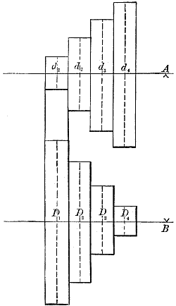
Fig. 561.
Example 1. Given the effective diameters
4.5 in. 9 in. 15 in. 21 in. on cone A,
— — 15 in. — „ B,
and the distance between centres equal to 50 inches.
Required the remaining diameters on cone b.
Since in this example the steps of the given pair are equal, we look for 15⁄50 = 0.30, in the extreme right-hand column of table; we will find it in the 11th line from the top; now looking along this line for the diameter of the other step, = 15⁄50 = 0.30, we will find it in column 10; consequently the numbers of this column may be taken as the diameters of the steps which are the companions or partners of those in the extreme right-hand column.
We can now easily determine the remaining members of the pairs to which 4.5 in., 9 in., and 21 in. steps respectively belong. To find the partner of the 4.5 step, we find 4.5⁄50 = 0.09 in the right-hand column, and look along the horizontal line on which 0.09 is placed till we come to column 10, in which we will find the number 0.4850; 0.4850 × 50 in. = 24.25 in. will be the effective diameter of the companion to the 4.5 in. step.
To find the partner to the 9 in. step, we proceed as before, looking for 9⁄50 = 0.18 in the right-hand column, and then along the horizontal line of 0.18 to column 10, then will 0.4113 × 50 in. = 20.57 in. be the required companion to the 9 in. step of cone a.
In like manner for the partner of the 21 in. step we get 0.1700 × 50 in. = 8.5 in. The effective diameter therefore will be,
4 .5 in. 9 in. 15 in. 21 in. on cone A,
24 .25 20 .57 15 in. 8 .5 „ B.
If the thickness of belt employed were 0.25 in. the actual diameters of steps would be,
4.25 8.75 14.75 20.75 on cone A,
24.00 20.32 14.75 8.25 „ B,
and the length of belt would be 2.9425 × 50 = 147.125 in.
Example 2. Given the effective diameters
6 in. 12 in. 18 in. 24 in. on cone A,
30 in. — — — „ B,
and the distance between centres = 40 in.
Required the unknown diameters on cone B.
We must, as before, first find the vertical column corresponding to the length of belt which joins the pair of steps 6 in/30 in. We find the number 6⁄40 = .15 in the right-hand column, and then look along its horizontal line for its partner 30⁄40 = 0.75. Since we do not find any number exactly equal to .7500, we must interpolate. For the benefit of those not familiar with the method of interpolation we will give in detail the method of finding intermediate columns of the table. On the aforesaid horizontal line we find in column 16 a number 0.7520, larger than the required 0.7500, and in column 15 a number 0.7014, smaller than 0.7500; evidently the intermediate column, containing the required 0.7500, must lie between columns 16 and 15. To find how far the required column is from column 16, we subtract as follows:
0.7520 0.7520
0.7500 0.7014
.0020 0.0506
then the fraction .0020⁄.00506 = 0.04 nearly will represent the position of the required intermediate column; namely, that its distance from column 16 is about 4⁄100 of the distance between the adjacent columns, 15 and 16.
To find other numbers in this intermediate column we have only to multiply the difference between the adjacent numbers of columns 16 and 15 by 0.04, and subtract the product from the number in column 16. But it is not necessary to find as many numbers of the intermediate columns as are contained in either of the adjacent columns; it is only necessary to find as many numbers as there are steps in each of the cone pulleys. We will now illustrate what has preceded, by finding the partner to the 12 in. step of cone a. Find, as before, the horizontal line corresponding to 12⁄40 = 0.30, then take the difference between the numbers 0.6413 and 0.5867 of columns 16 and 15, and multiply this difference, 0.0546, by 0.04; this product = 0.0022 subtracted from 0.6413, will give 0.6391, a number of the intermediate columns corresponding to the length of belt of the present problem. Multiplying by the distance between the axes = 40 in. we get 0.6391 × 40 = 25.56, for the diameter of the step of cone b which is partner to the 12 in. step of cone a.
To find the companion to the 18 in. step, we proceed in the same manner, looking for the horizontal line 18⁄40 = 0.45, and interpolating as follows:
0.5094 - (0.5094 - 0.4500) × 0.04 = 0.5070.
Consequently, 0.5070 × 40 in. = 20.28 in. will be the required partner of the 18 in. step.
In like manner, for the 24 in. step, we have
0.3500 - (0.3500 - 0.2840) × 0.04 = 0.3474, and 0.3474 × 40 = 13.90.
The effective diameters are therefore
6 in. 12 in. 18 in. 24 in. on cone A.
30 25 .56 20 .28 13 .9 „ B.
The actual diameters, when thickness of belt = 0.20 in., are:
5 .8 11 .8 17 .8 23 .8 on cone A.
29 .8 25 .36 20 .08 13 .7 „ B.
And the length of belt will be:
[3.5080 - (3.5080 - 3.4137) × 0.04] × 40 in. = 140.17 in.
Example 3. Given the effective diameters:
12 in. 18 in. 24 in. 30 in. on cone A,
33 in. — — — „ B,
and the distance between the centres = 60 in.
Required the remaining diameters on cone b.
The horizontal corresponding to 12⁄60 = 0.20 lies 2⁄3rd way between the horizontal line, corresponding to 0.18 and 0.21; the number 33⁄60 = 0.5500, corresponding to the companion of the 12 in. step, will therefore lie 2⁄3rd way between the horizontal lines 0.18 and 0.21. We have now to find two numbers on this 2⁄3rd line, of which one will be less and the other greater than 0.5500. An inspection of the table will show that these greater and less numbers must lie in columns 13 and 12. The numbers on the 2⁄3rd line itself may now be found as follows:
In column 13, 0.5750 - 2⁄3(0.5750 - 0.5513) = 0.5592.
In column 12, 0.5213 - 2⁄3(0.5213 - 0.4967) = 0.5049.
0.5592 will be the number on the 2⁄3rd line, which is greater than 0.5500, and 0.5049 will be the one which is less than 0.5500. The position of the intermediate column, corresponding to the length of belt of the present example, may now be found, as before, briefly. It is:
0.5592 - 0.5500 = 0.0092 = 0.17.
0.5592 - 0.5049 = 0.0543
Consequently the required column lies nearest column 13, 17⁄100th way between columns 13 and 12. To find any other number in the required column, we have only to multiply the difference between two adjacent numbers of columns 13 and 12 by 17⁄100, and subtract the product from the number in column 13. For example, to find the diameter of the partner to the 18 in. step of cone a, we find the numbers 0.4750 and 0.4177 of columns 13 and 12, which lie on the horizontal line corresponding to 18⁄60 = 0.30; the difference, 0.0573, between the two numbers is multiplied by 0.17, and the product, 0.0573 × 0.17 = 0.0097, subtracted from 0.4750. This last difference will equal 0.4653, and will be the number sought. If we now multiply by 60, we will get 27.92 in. as the effective diameter of that step on cone b which is the partner to the 18 in. step of cone a.
To find the companion of the 24 in. step, we proceed after the same fashion; the horizontal line 24⁄60 = 0.40 lies 1⁄3rd way between 0.39 and 0.42; hence,
In column 13, 0.3900 - 1⁄3(0.3900 - 0.3594) = 0.3798;
In column 12, 0.3294 - 1⁄3(0.3294 - 0.2975) = 0.3188;
And 0.3798 - (0.3798 - 0.3188) × 0.17 = 0.3694.
The required effective diameter of the step, which is partner to the 24 in. step, will therefore be 0.3694 × 60 = 22.16 in.
In like manner we obtain partner for the 30 in. step, thus:
In column 13, 0.2944 - 2⁄3(0.2944 - 0.2600) = 0.2715.
In column 12, 0.2300 - 2⁄3(0.2300 - 0.1940) = 0.2060.
Also 0.2715 - (0.2715 - 0.2060) × 0.17 = 0.2604, and 0.2604 × 60 in. = 15.62 in. = diam. of step belonging to the same belted pair as the 30 in. step of cone a.
The effective diameters will be:
12 in. 18 in. 24 in. 30 in. on cone A,
33 27 .92 22 .16 15 .62 „ B,
and the actual diameters when belt is 0.22′′ thick:
11.78 17.78 23.78 29.78 in.
32.78 27.70 21.94 15.40
and the length of belt is found to be:
[3.2252 - (3.2252 - 3.1310) × 0.17] × 60 in. = 192.55 in.
In all the preceding problems it should be noticed that we arbitrarily assumed all the steps on one cone, and one of the steps on the other cone. It will be found that all of the practical problems relating to cone-pulley diameters can finally be reduced to this form, and can consequently be solved according to the methods just given.
For those who find difficulty in interpolating, the following procedure will be found convenient: Estimate approximately the necessary length of belt, then divide this length by the distance between the centres of the cone pulleys; now find which one of the 33 lengths of belt (per unit’s distance apart of the centres) given in the table is most nearly equal to the quotient just obtained, and then take the vertical column, at the head of which it stands, for the companion to the right-hand column. Those numbers of these companion columns which are on the same horizontal line will be the companion steps of a belted pair. The table is so large, that in the great majority of cases not only exact, but otherwise satisfactory values can be obtained by this method, without any interpolation whatever.”
The teeth of the back gear should be accurately cut so that there is no lost motion between the teeth of one wheel, and the spaces of the other, because on account of the work being of large diameter or of hard metal (so as to require the slow speed), the strain of the cut is nearly always heavy when the back gear is in use, and the strain on the teeth is correspondingly great, causing a certain amount of spring or deflection in the live spindle and back gear spindle. Suppose then, that at certain parts of the work there is no cut, then when the tool again meets the cut the work will meet the tool and stand still until the lost motion in the gear teeth and the spring of the spindles is taken up, when the cut will proceed with a jump that will leave a mark on the work and very often break the tool. When the cut again leaves the tool a second jump also leaving a mark on the work will be made. If the teeth of the gears are cut at an angle to the axial line of the spindle, as is sometimes the case, this jumping from the play between the teeth will be magnified on account of a given amount of play, affording more back lash in such gears.
The teeth of the wheels should always be of involute and not of epicycloidal form, for the following reasons. The transmission of motion by epicycloidal teeth is exactly uniform only when their pitch circles exactly coincide, and this may not be the case in time because of wear in the parts as in the live spindle journals and the bearings, and the back gear spindle and its bearings, and every variation of speed in the cut, however slight it may be, produces a corresponding mark upon the work. In involute teeth the motion transmitted will be smooth and equal whether the pitch lines of the wheels coincide or not, hence the wear of the journals and bearings does not impair their action.
The object of cutting the teeth at an angle is to have the point of contact move or roll as it were from one end to the other of the teeth, and thus preserve a more conterminous contact on the line of centres of the two wheels, the supposition being that this would remove the marks on the work produced by the tremor of the back gear. But such tremor is due to errors in the form of the teeth, and also in the case of epicycloidal teeth from the pitch lines of the teeth not exactly coinciding when in gear.
The pitch of the teeth should be as fine as the requisite strength, with the usual allowance of margin for wear and safety will allow, so as to have as many teeth in continuous contact as possible.
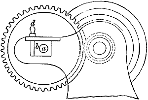
Fig. 562.
Various methods of moving the back gear into and out of gear with the cone spindle gears are employed. The object is to place the back gears into gear to the exact proper depth to hold them securely in position, and to enable the operator to operate the gears without passing to the back of the lathe. Sometimes a sliding bearing box, such as shown in Fig. 562, is employed; a is the back gear spindle, b its bearing box, and d a pin which when on the side shown holds b in position, when the back gear is in action. To throw it out of action d is removed, b pushed back, and d inserted in a hole on the right hand of b; the objection is that there is no means of taking up the wear of b, and it is necessary to pass to the back of the lathe to operate the device.
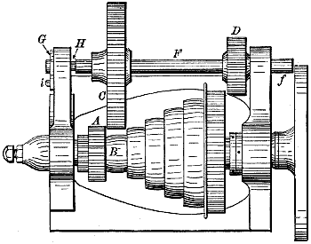
Fig. 563.
Another plan is to let the back gear move endwise and bush its bearing holes with hardened steel bushes. This possesses the advantage that the gear is sure, if made right, to keep so, but it has some decided disadvantages: first, the pinion a, Fig. 563, must be enough larger than the smallest cone-step b to give room between b and c for the belt, and this necessitates that d also be larger than otherwise; secondly, the gear-spindle f projects through the bearing at f, and this often comes in the way of the bolt-heads used for chucking work to the face plate. The method of securing the spindle from end motion is as follows: On the back of the head is pivoted at i, a catch g, and on the gear shaft f are two grooves. As shown in the sketch, g is in one of these grooves while h is the other, but when the back gear is in, g would be in h.
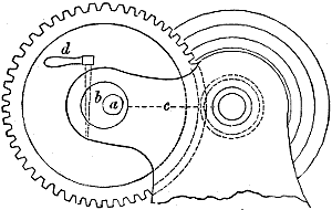
Fig. 564.
Sometimes a simple eccentric bush and pin is used as in Fig. 564, in which a is the spindle journal, b a bush having bearing in the lathe head, and d a taper pin to secure b in its adjusted position.
In large heavy lathes having many changes of speed, there are various other constructions, as will be seen upon the lathes themselves in the various illustrations concerning the methods of throwing the back gear in and out. The eccentric motion shown in Fig. 573 of the Putnam lathe, is far preferable to any means in which the back-gear spindle moves endways, because, as before stated, the end of the back-gear spindle often comes in the way of the bolts used to fasten work to the large face plate. This occurs mainly in chucked work of the largest diameter within the capacity of the lathe.
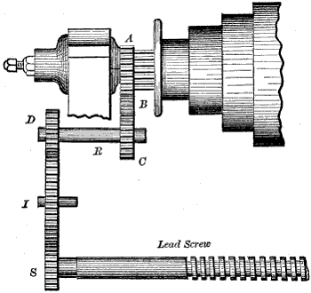
Fig. 565.
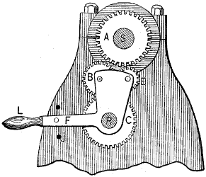
Fig. 566.
In many American lathes the construction of the gearing that conveys motion from the live spindle is such that facility is afforded to throw the change gears out of action when the lathe is running fast, as for polishing purposes, so as to save the teeth from wear. Means are also provided to reverse the direction of lead screw or feed screw revolution. An example of a common construction of this kind is shown in Fig. 565, in which the driving wheel a is on the inner side of the back bearing as shown. It drives (when in gear) a pair of gears, one only of which is seen in the figure at b, which drives c, and through r, d, i, and s, the lead screw. A side view of the wheel a and the mechanism in connection therewith is shown in Fig. 566, in which s represents the live spindle and r is a spindle or shaft corresponding to r in Fig. 565. l is a lever pivoted upon r and carrying two pinions b and e; pinion b is of larger diameter than e, so that b gears with both c and e (c corresponding to wheel c in Fig. 565), while e gears with b only.
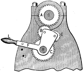
Fig. 567.
With the lever l in the position shown, neither b nor e engages with a, hence they are at rest; but if lever l be raised as in Fig. 567, b will gear with wheels a and c, and motion will be conveyed from a to c, wheel e running as an idle wheel, thus c will revolve in the same direction as the lathe spindle.
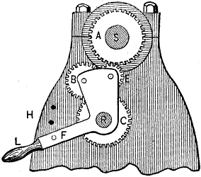
Fig. 568.
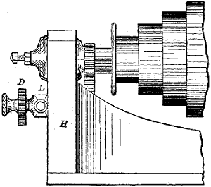
Fig. 569.
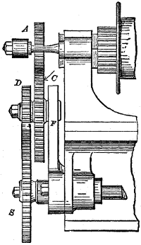
Fig. 570.
But if lever l be lowered as in fig. 568, then wheel e will gear with and receive motion from a, which it will convey to b, and c will revolve in the opposite direction to that in which the lathe spindle runs. To secure lever l in position, a pin f passes through it and into holes as i, j, provided in the lathe head. Lever l is sometimes placed inside the head, and sometimes outside as in Fig. 569, and it will be obvious that it may be used to cut left-hand threads without the use of an extra intermediate change gear, which is necessary in the construction shown in Fig. 570, in order to reverse the direction of lead screw revolution.
Sometimes the pin f is operated by a small spring lever attached to l, so that the hand grasps the end of l and the spring lever simultaneously, removing f from the hole in h, and therefore freeing l, so as to permit its operation. By relaxing the pressure on the small spring lever pin f finds its own way into the necessary hole in h, when opposite to it, without requiring any hand manipulation.
In larger lathes the lever l is generally attached to its stud outside the end bearing of the head h.
It is preferable, however, that the device for changing the direction of feed traverse be operative from the lathe carriage as in the Sellers lathe, so that the operator need not leave it when it is necessary to reverse the direction of traverse.
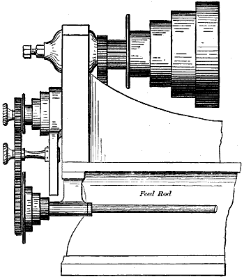
Fig. 571.
The swing frame, when the driving gear d is outside of the back bearing (as it is in Fig. 570), is swung from the axis of the lead screw as a centre of motion, and has two slots for receiving studs for change wheels. But when the driving gear is inside the back bearing as in Fig. 571, the swing frame may be suspended from the spindle (r, Fig. 565) that passes through the lathe head, which may also carry the cone for the independent feed as shown in Fig. 571, no matter on which side of the lathe the lead screw and feed rod are. This affords the convenience that when both lead screw and feed rod are in front of the lathe, the feed may be changed from the screw cutting to the rod feed, or vice versâ, by suitable mechanism in the apron, without requiring any change to be made in the driving gears.
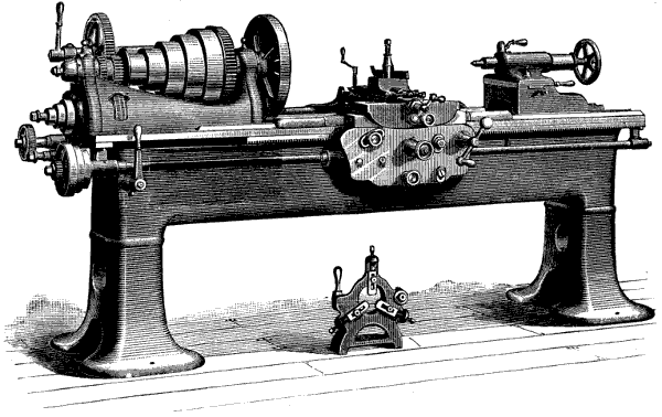
Fig. 572.
Large image (143 kB).
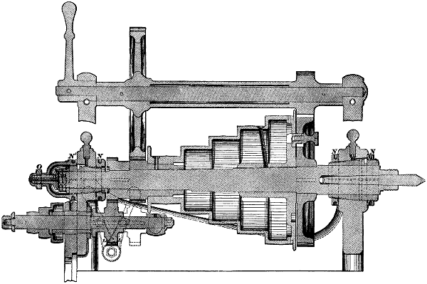
Fig. 573.
In the lathe shown in Fig. 572, which is from the design of S. W. Putnam, of the Putnam Tool Company of Fitchburg, Massachusetts, the cone pinion for the back gear, and that for driving the feed motion, are of the same diameter and pitch, so that the gear-wheel l in Fig. 573 may (by means of a lever shown dotted in) be caused to engage with either of them. When the latter is used in single gear it would obviously make no difference which wheel drives l, but when the back gear is put in and l is engaged with the cone pinion, its speed corresponds to that of the cone, which being nine times faster than the live spindle, enables the cutting of threads nine times as coarse as if the back gear was not in use. This affords very great advantages for cutting worms and threads of coarse pitches.
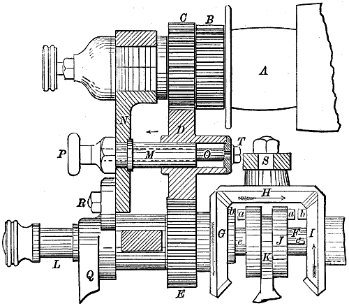
Fig. 574.
An excellent method of changing the direction of feed motion, and of starting or stopping the same, is shown in Fig. 574, which represents the design of the Ames Manufacturing Company’s lathe.
In the figure, a is the small step of the lathe cone, b the pinion to drive the back gear, c a pinion to drive the feed gear, giving motion to d, which drives e, the latter being fast to g and rotating freely upon the shaft f, g drives h, which in turn drives i. The clutch j has a featherway into which fits the feather c, on the shaft f, so that when the clutch rotates it rotates j through the medium of c; k is a circular fork in a groove in j, and operated by a lever operated by a rod running along the front of the lathe bed. This rod is splined so that a lever carried by the apron or feed-table, having a hub and enveloping the rod, may by means of a feather filling into the spline operate the rod by partly rotating it, and hence operate k. Suppose now that this lever stands horizontal, then the clutch j would stand in the position shown in the cut, and d, e, g, h, and i, would rotate, while f would remain stationary. By lifting the lever, however, j would be moved laterally on f (by means of k) and the lug a on j would engage with lug b on g, and g would drive j, which through c would drive f, on which is placed a change gear at l, thus traversing the carriage forward. To traverse it backward the lever would be lowered or depressed below the horizontal level moving k, and therefore j, to the right, so that lug a would engage with lug b on i, hence f would be driven by i, whose motion is in an opposite direction to g, as is denoted by the respective arrows.
To throw all the feed motion out of gear, to run the lathe at its quickest for polishing, &c., the operation is as follows.
m is tubular and fast in n and affords journal bearing to wheel d. Through m passes stud o, having a knob handle at p. At the end of the hub of d is a cap fast in d, the latter being held endways between the shoulder shown on o and the washer and nut t. If then p be pulled outwards o will slide through m, and through the medium of t will cause d to slide over m, in the direction of the arrow, and pass out of gear from c, motion therefore ceasing at c.
q is the swing frame for the studs to carry the change wheels, and r a bolt for securing q in its adjusted position. s is a journal and bearing for h.
If it be considered sufficient the feed motion on small lathes (instead of feeding in both directions on the lateral and cross feeds as in the Putnam Lathe), may feed in the direction from the dead to the live centre, and in one direction only on the cross slide.
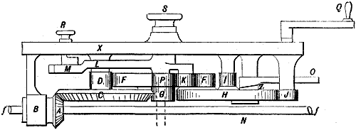
Fig. 575.
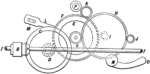
Fig. 576.
An example of a feed motion of this kind is shown in Figs. 575 and 576; f f is the feed spindle splined and through the medium of a feather driving the bevel pinion a having journal bearing in b. Pinion a drives the bevel gear c, which is in one piece with pinion d. The latter drives gear f, which drives pinion k, which is carried on a lever l, pivoted on the stud which carries f, so that by operating l, pinion k is brought into gear with pinion p, which is fast upon the cross-feed screw, and therefore rotates it to effect the automatic cross feed.
As shown in the cut, the lever l is in such a position as to throw k out of gear with p, and the cross feed screw is free to be operated by the handle by hand. At m is a slot in l in which operates a cam or eccentric, one end of which projects into l, while at the other end is the round handle r, Fig. 575, which is rotated to raise or lower that end of l so as to operate k. To operate the saddle or carriage the motion is continued as follows:—at the centre of f is a pinion gear g which operates a gear h, which is in one piece with the pinion i, and the latter is in gear with the rack running along the lathe bed.
If the motion from a to i was continuous, the carriage feed or traverse would be continuous, but means are provided whereby motion from f to i may be discontinued, as follows:—A hand traverse or feed is provided. j, Figs. 575 and 576, is carried by a stud having journal bearing in a hub on x and receiving the handle q; hence by operating q, j is rotated, operating the gear h, upon which is the pinion i, which is in gear with the rack running along the lathe bed.
To lock the carriage in a fixed position, as is necessary when operating the cross feed on large radial surfaces, the following device is provided:—n is a stud fixed in a hub on x, and having a head which overlaps the rim of h, as shown in figure. On the other side of that rim is a washer z on the same stud having a radial face also overlapping the rim of h, but its back face is bevelled to a corresponding bevel on the radial face on the hub of lever o (the hub of o being pivoted on the same stud). When therefore o is depressed the two-bevel face of the hub of o forces the washer z against the face of the wheel h, whose radial faces at the rim are therefore gripped between the face of the collar n and that of the washer z, hence h is locked fast. By raising the end of lever o, z is released and h is free to rotate.
Both the carriage feed and cross feed can only be traversed in one direction so far as these gears and levers are concerned, but means are provided on the lathe headstock for reversing the direction of motion of the feed spindle f so as to reverse the direction of the feeds. It will be observed that so long as f rotates, a, c, d, and f rotate, the remaining motions only operating when s is screwed up.
In order to obtain a delicate tool motion from the handle q it is necessary to reduce the motion between j and i as much as possible, a point in which a great many lathes as at present constructed are deficient, because q, although used to simply traverse the carriage along the bed, in which case rapid motion of the latter is desirable, is also used to feed the tool into corners when the lathe has no compound rest to put on light cuts on radial faces, hence it should be capable of giving a delicate tool motion.
On account of the deficiency referred to it is often necessary to put on a fine radial cut by putting the feed traverse in gear, and, throwing the feed screw gear out of contact with the other change wheels, pull it around by hand to put on the cut. In compound slide rests these remarks do not apply, because the upper part of the rest may be used instead of the handle q.
Many small lathes are provided with a tool rest known as the elevating rest, or weighted lathe.
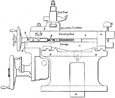
Fig. 577.
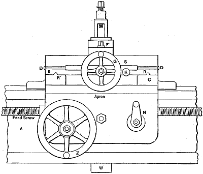
Fig. 578.
An excellent example of an elevating rest for a weighted lathe is shown in Figs. 577 and 578, which represent the construction in the Pratt and Whitney lathe. a is the lathe shears upon which slides the carriage provided with V slideways r for the sliding piece b, and provided at the other end with the guides h. The cross slide s is pivoted upon b at d, and fits at the other end between the guides h. At e is the elevating screw which when operated raises or lowers that end of the elevating rest to adjust the tool height. This also affords an excellent means of making a minute adjustment for depth of tool cut. The tool rest f is bolted to s.
The weight w is suspended from s and, therefore, holds one end of s to b, the lathe to c, and c to a; at the other end the weight holds s to c (through the medium of the elevating screw e) and c to a. The cross feed nut n is fast to s, the cross feed screw being operated by hand wheel g. b is provided with the V slideways r, which slide upon corresponding V slides r′ upon c; p is a lug cast upon c, and k is a screw threaded in b. When the end of screw k abuts against p the motion of s, and, therefore, of the cutting tool t, towards the work is arrested, hence when the tool is adjusted to the proper depth of cut, k is operated to abut firmly against p, and successive pieces may be turned to the same diameter without requiring each piece to be measured for diameter. n is the handle for opening and closing the nut for the feed screw q, and z is the wheel for the hand feed traverse. The length of cross feed motion is determined by the length of the cross V slides r′.
This class of rest possesses the advantage that no lost motion in the slides occurs by reason of the wear, because the weight keeps the parts in constant contact notwithstanding such wear; on the other hand, however, the slide Vs sustain the extra wear due to the weight w in addition to the weight of the carriage. Lathes of this class are intended for light work, and are less suited for boring than for plain turning; they are, however, very convenient, and are preferred by many to any other kind of lathe for short and light work.
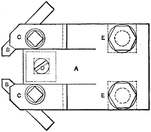
Fig. 579.
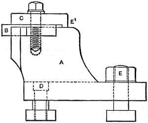
Fig. 580.
The tool rest being removable may be supplanted by other special forms of rest. Thus Figs. 579 and 580 represent a special rest for carrying two tools to cut pieces of work to the exact same length. Bolts d and e are to secure the rest a to the elevating rest, and c c are the clamps for the two tools b.
Large image (334 kB).
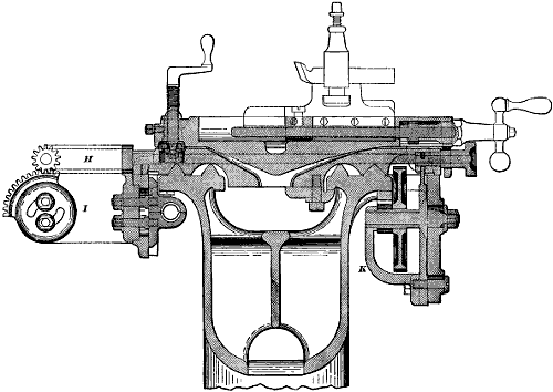
Fig. 581.
Fig. 581 represents a cross sectional view of the Putnam Tool Company’s gibbed elevating rest, there being a gib on the underneath side of the front shear. The elevating screw is pivoted by a ball joint. By employing a gib instead of a weight, the bed may be provided with cross girts or ribs joining the two sides of the shear, thus giving much greater stiffness to it.
Large image (107 kB).
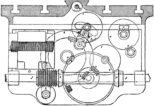
Fig. 582.
Large image (68 kB).
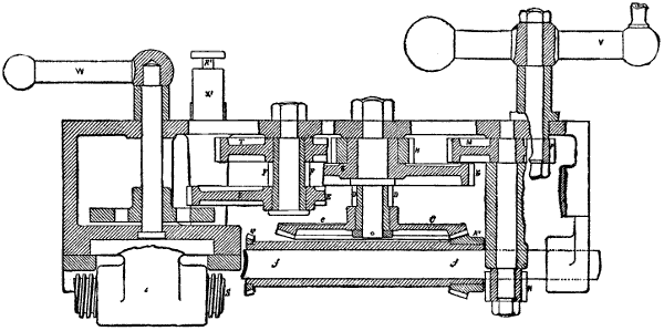
Fig. 583.
Large image (106 kB).
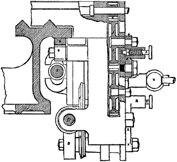
Fig. 584.
Figs. 582, 583, and 584 represent a lathe feed motion by William Munzer, of New York. The object in this motion is to insure that no two feeds can be put into operation simultaneously, because putting the feed in motion in one direction throws it out of gear for either of the others. Another object is to have the transmitting motion as direct as possible so as to avoid the rotation of any wheels not actually necessary for the transmission of the motion; and a third object is to enable the throwing out of gear of all wheels (when no feed motion at all is required) without leaving the apron.
The means employed to effect these objects are as follows:—
In Fig. 582 f represents the independent feed spindle and s the lead-screw: f is splined to drive a, a′ and a′′, which is a sleeve in one piece, and consists of a circular rack at a, a bevel pinion at a′, and a second bevel pinion at a′′. This sleeve may be operated in either direction along f by rotating the pinion b. As shown in the cut a′ and a′′ are both out of gear with the bevel-wheel c, but if b be rotated to the right then a′ will be in gear with c, or if it be operated to the left then a′′ will be in gear with c. Now the direction of rotation of c will be governed by which pinion, a′ or a′′, drives it, and these are the means by which the direction of the feed traverse and also of the cross feed is determined.
If none of the feeds are required to operate, the sleeve occupies the position shown in the cut, and the circular rack at a simply rotates while b and all other parts remain at rest. On the same central pin as c is the pinion d driving a spur gear e′′. On the same centre pin as e is the gear f driving g, which is on the same central pin as c and d. The gear h is fixed to and rotates with g and drives i; all these gears serving to reduce the speed of motion when operating to feed the carriage traverse in either direction.
A gear j is carried on the end of a lever k, being pivoted at l. In the position shown j is out of gear with all gears, but it may be swung to the right so as to engage with wheel i and wheel m, and convey the motion of i to m. Upon the same spindle as m is the pinion n, engaging with the rack o, which is fast on the lathe bed. This completes the automatic feed traverse.
For a hand feed traverse, pinion p is employed to drive m, which is fast to n. The cross feed is self-acted by moving lever k to the left, causing it to engage with pinion q as well as with t, q being fast on the cross feed screw. To lock j in either of its three positions there is provided on lever k a spring locking pin r, shown clearly in Fig. 584, which represents an irregular section of the gearing viewed from the headstock of the lathe. The pin r is pressed inward by the spiral spring shown, and has a conical end fitting into holes provided in the apron to receive it. There are three of these holes, shown in dotted lines at a b c in Fig. 582. When the pin is in a the lever k, and therefore wheel j, Fig. 582, is locked out of gear; when it is in hole b wheel j is locked in gear with i and m, and when it is in c the wheel j is in gear with t and q, and the cross feed is actuated.
A similar locking device is provided for the pinion b for actuating a; thus in Fig. 582 b is the lever, the spring pin being at r′′; or referring to Fig. 584, x is the lever fast at x on the pin driving b, and r′ is the spring pin.
The nut for the lead screw is secured either in or out of gear with the screw in the same manner, x′, Fig. 583, being the lever and r′′ the spring pin.
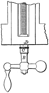
Fig. 585.
In screw cutting the cutting tool requires to be withdrawn from the thread while the carriage traverses back, and it is somewhat difficult to know just how far to move the tool in again in order to put on a proper depth of cut. To facilitate this the device shown in Fig. 585 (which is taken from the “American Machinist,”) is sometimes employed.
It consists of a ring c inserted between the cross slide d and the handle hub b having journal bearing on and rotating with the latter. When the first cut is put on, the mark on c is coincident with that on d, and the ring is then, while the first cut is traversing, moved (supposing the cross feed screw to have a right-hand thread) to the left, as shown in the figure, to the amount the handle will be required to move to the right to put on the next cut, and when the next cut is put on the handle will be moved the distance it was moved to withdraw the tool for the back traverse, and in addition enough to make the marks coincide, then while the second cut is being taken the ring is again moved to the left, as in the cut, to give the depth of cut for the next traverse, and so on.
If the cross feed screw has a left-hand thread, the mark on the ring would require to be moved to the right instead of to the left of the mark on d. It is obvious that this answers the same purpose, but is more exact than the chalk mark before referred to, and, indeed, that chalk mark could be used in the same way, leaving the chalk mark d and rubbing out that on c while the cut is proceeding and making a new one for the next cut.
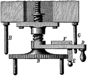
Fig. 586.
Another device for use on lathes specially designed for screw-cutting is shown in Fig. 586, in which a represents the cross feed screw. It is fast to the notched wheel b, and is operated by it in the usual way. c is a short screw which provides journal bearing for the screw a by a plain hole. It is screwed on the outside, and the plate in which it fits acts as its nut. It is fast to the handle d, and is in fact operated by it. The handle or lever is provided with a catch e, pivoted in the enclosed box f, which also contains a means of detaining the catch in the notches of the wheel, or of holding it free from the same when it is placed clear. If, then, the lever d be moved back and forth the feed screw a, and hence the slide rest, will be operated; while, if the catch be placed in one of the notches on the wheel b, both the screws, a and c, will act to operate the rests. When, therefore, the tool is set to touch the diameter of the work, the catch e is lifted and the feed wheel b rotated, putting on the cut until the catch e will fall into the next notch in b, the lever d resting in the meantime on the stud g. When the cut is carried along the work to the required distance the tool is withdrawn by moving d over until it rests upon stud or stop h. While the slide rest is traversing back e is lifted and b rotated so that e will fall into the next notch, and when the tool starts forward again d is moved over from h to g, as shown in the figure, and the tool cut is put on.
When the device is not required to be used e is thrown out, d rests on e, and the feed is operated in the ordinary manner.
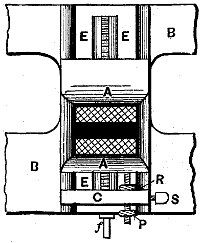
Fig. 587.
A simple attachment for regulating on a slide rest the depth of tool cut in screw cutting or for adjusting the cut to a requisite diameter when a number of pieces are to be turned to diameter by a finishing cut, is shown in Fig. 587, in which b represents the slide rest carriage, and e the cross slide on which the slide rest a is traversed by means of the cross feed screw f. A screw is screwed into the rest, as shown, carrying the two circular milled edge nuts r p; the screw passes an easy fit through the piece c, which is capable of being fixed in any position along the slide e by means of the set screw s; the nut r is set in such a position on the screw that it will abut against c when the tool is clear of the work surface (for the back traverse) while p may be used in two ways:—First it may be set so that when it comes against c the thread is cut to the required depth, and thus act as stop to give the thread depth without trying the gauge: or it may be used to answer the same purpose and in the same way as the ring c in Fig. 585.
The use of this device as a stop to gauge the thread depth is confined to such lengths of work as enable the tool to cut several pieces without requiring regrinding, because when the tool is removed to grind it, it is impracticable to set it exactly the same distance out from the tool post, hence the adjustment of p becomes destroyed. It is better, therefore, in most cases where a number of threads of equal pitch and diameter are to be cut, to rough them all out, cutting the threads a little above the gauge diameter so as to leave a finishing cut to be taken. In roughing out, however, the nut p may still be used to regulate the depth.
For the finishing cut the tool may be ground and p adjusted to give the requisite depth of cut, taking a single traverse over each thread to finish it. This, of course, preserves the tool and enables it to finish a larger number of threads without regrinding, and the consequent readjustment of p.
It is obvious that the nut p may be employed in the same manner to turn a number of plain pieces to an equal diameter.
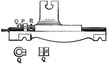
Fig. 588.
It is preferable in a device of this kind, however, to employ the two adjusting nuts p and q in Fig. 588, q being a clamp nut that can be closed by a screw so as to firmly grip the threaded stud. q is adjusted so that when p abuts against it the tool will cut to the correct diameter when it is moved in as far as nuts p q will permit. The use of the second nut p is as follows:—Suppose a first cut has been taken and p may be screwed up to just meet the face of clamp c. Then while the carriage is traversing, p may be screwed back towards q sufficiently to put on the next cut, and so on, so that p is used to adjust the depths of the roughing, and q that of the finishing cut.
Sometimes a feed motion to a slide rest is improvised by what is known as the star feed, the principle of action of which is as follows: Upon the outer end of the feed screw of the boring bar or slide rest, as the case may be, is fastened a piece of iron plate, which, from having the form in which stars are usually represented, is called the star. If the feed is for a slide rest a pin is fastened to the lathe face plate or other revolving part, in such a position that during the portion of the revolution in which it passes the star it will strike one of the star wings, and move it around sufficiently to bring the next wing into position to be struck by the pin during its succeeding revolution. When the feed is applied to a revolving boring bar the construction is the same, but in this case the pin is stationary and the star revolves with the feed screw of the bar.
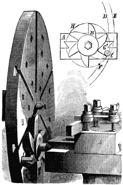
Fig. 589.
In Fig. 589 is shown a star feed applied to a slide rest. a is the slide rest, upon the end of the feed screw of which the star, b, is fitted. c is a pin attached to the face plate of the lathe, which, as it revolves, strikes one of the star wings, causing it to partly rotate, and thus move the feed screw. The amount of rotation of the feed screw will depend upon the size of the star and how far the circle described by the pin c intersects the circle described by the extreme points of the star wings. Thus the circles denoted by d e show the path of the pin c; the circle f h the path of the star points, and the distance from f to g the amount which one intersects the other. It follows that at each revolution of c an arm or wing of the star will be carried from the point g to point f, which, in this case, is a sixth of a revolution. If more feed is required, we may move the pin c, so that it may describe a smaller circle than d e, and cause it to intersect f h to a greater extent, in which case it will move the star through a greater portion of its revolution, striking every other wing and doubling the amount of feed.
It will be observed that the points f and g are both below the horizontal level of the slide rest’s feed screw, and therefore that the sliding motion of the pin c upon the face of the star wings will be from the centre towards the points. This is better, because the motion is easier and involves less friction than would be the case if the pin contact first approached and then receded from the centre, a remark which applies equally to all forms of gearing, for a star feed is only a form of gearing in which the star represents a tooth wheel, and the pin a tooth in a wheel or a rack, according to whether its line of motion is a circle or a straight line.
It is obvious that in designing a star feed, the pitch of the feed screw is of primary importance. Suppose, for example, that the pitch of a slide rest feed screw is 4 to an inch, and we require to feed the tool an inch to every 24 lathe revolutions; then the star must have 6 wings, because each revolution of the screw will move the rest 1⁄6 in., while each revolution of the pin c will move the star 1⁄6 of a revolution, and 4 × 6 = 24. To obtain a very coarse feed the star attachment would require to have two multiplying cogs placed between it and the feed screw, the smaller of the cogs being placed upon the feed screw.
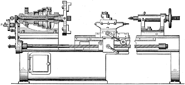
Fig. 590.
In many lathes of European design, the feeds or some of them, are actuated by ratchet handles, operated by an overhead shaft, having arms which rock back and forth. Thus in Fig. 590 is a lathe on which there is provided at a crank disc, carrying in a dovetail slot a pin p, for rocking the overhead shaft from whose arms a chain is attached which may be connected to the ratchet handle shown on the cross-feed screw, the weight being for the purpose of carrying that handle down while the chain pulls it up. To regulate the amount of feed the pin p is adjusted in the slot in a, or the chain may be attached in different positions along the length of the ratchet arm, the weight being provided with a set screw so that it may be set in any required position along the ratchet arm.
Tool-holding Devices.—Perhaps no part of a lathe is found in American practice with so many different forms of construction as the device for holding the cutting tool. The requirements for a lathe to be used on light work and where frequent changes in the position of the tool are necessary, are quite different from those for a lathe intended to take as heavy a cut as the lathe will properly drive, and wherein tools having the cutting edge at times standing a long way out from the tool post (as sometimes occurs in the use of boring tools). In the former case a single holding screw will suffice, possessing the advantage that the tool may be quickly inserted, adjusted for height and set to one side or the other, with a range of motion which often permits of a tool that has taken a parallel cut being moved in position to capacitate it to take a facing one, which would not be the case were its capacity for side adjustment limited.
VOL. I. TOOL‑HOLDING AND ADJUSTING APPLIANCES. PLATE VII.
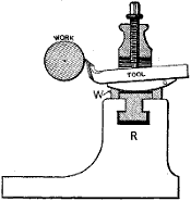
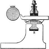
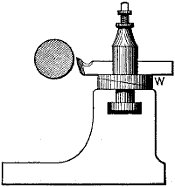
Fig. 591. Fig. 592. Fig. 593.
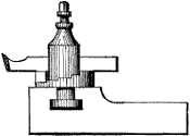
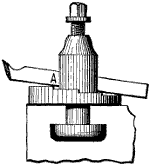
Fig. 594. Fig. 595. Fig. 596.
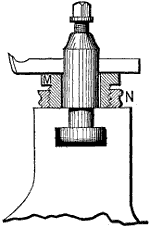
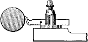
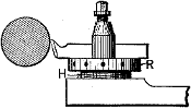
Fig. 597. Fig. 598. Fig. 599.
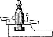
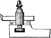
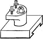
Fig. 600. Fig. 601. Fig. 602.
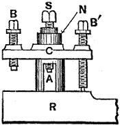
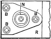
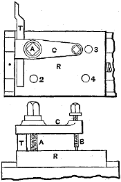
Fig. 603. Fig. 604.
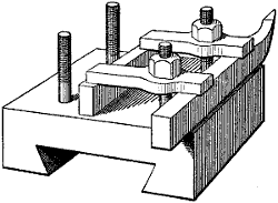
Fig. 606. Fig. 605.
In the case of the common American lathe having a self-acting feed and no compound rest, the tool post is usually employed, the rest being provided with a T slot such as shown in Fig. 577. This enables the tool post to be moved from side to side of the tool rest, and swing around in any required position. In connection with such tool posts various contrivances are employed to enable the height of the cutting edge of the tool to be readily adjusted. Thus in the Fig. 591, the tool post is surrounded by a cupped washer w, and through the slot in the tool post passes a gib g, which may be moved endways in the slot and thus elevates or depresses the tool point.
The objection to this is that the tool is not lifted parallel, or in other words is caused to stand out of its proper horizontal position which alters the clearance of the tool, and by presenting the angles forming the tool edge in an improper position, with relation to the work, impair its cutting qualification, as will be shown hereafter when treating of lathe cutting tools.