Volume 1 — Chapter XIV.—MEASURING MACHINES, TOOLS, AND DEVICES.
Reading edition
Measurements are primarily derived in Great Britain and her colonies, and in the United States, from the English Imperial or standard yard. This yard is marked upon a bar of “Bailey’s metal” (composed of 16 parts copper, 21⁄2 parts tin, and 1 part zinc), an inch square and 38 inches long. One inch from each end is drilled a hole about three-quarters through the whole depth of the bar, into which are fitted gold plugs, whose upper end faces are level with the axis of the bar. Across each plug is marked a fine line, and the distance between these lines was finally made the standard English yard by an Act of Parliament passed in 1855. A copy of this bar is in the possession of the United States Government at Washington, and all the standard measuring tools for feet, inches, &c., are derived from subdivisions of this bar.
The standard of measurement in France and her colonies, Italy, Germany, Portugal, British India, Mexico, Roumania, Greece, Brazil, Peru, New Granada, Uruguay, Chili, Venezuela, and the Argentine Confederation, is the French mètre, which is also partially the standard in Austria, Bavaria, Wurtemberg, Baden, Hesse, Denmark, Turkey, and Switzerland. It consists of a platinum bar, called the “mètre des archives,” whose end faces are parallel, and the length of this bar is the standard mètre. But as measuring from the ends of this bar would (from the wear) impair its accuracy, a second bar, composed of platinum and iridium, has been made from the “mètre des archives.” This second bar has ruled upon it two lines whose distance apart corresponds to the length of the “mètre des archives,” and from the distance between these lines the subdivisions of the mètre have been obtained.
As all metals expand or contract under variations of temperature, it is obvious that these standards of length can only be accurate when at some given temperature: thus the English bar gives a standard yard when it is at a temperature of 62° Fahr., while the French standard bar is standard at a temperature of 32° Fahr., which corresponds to 0 in the centigrade thermometer. But if a bar is copied from a standard, and is found to be too short, it is obvious that if its amount of expansion under an increase of temperature be accurately known, it will be an accurate standard at some higher temperature, or in other words, at a temperature sufficiently higher to cause it to expand enough to compensate for its error, and no more.
As all bars of metal deflect from their own weight, it is obvious that the bar must be supported at the same points at which it rested when the lines were marked, and it has been determined by Sir George Airy, that the best position for the points of support for any bar may be obtained as follows: Multiply the number of the points of support by itself (or, as it is commonly called, “square it”), and from the sum so obtained subtract 1. Then subtract the square root of the remainder, which gives a sum that divided into the length of the bar will represent the distance apart for the points of support. It will be obvious that the points of support must be at an equal distance from each end of the bar.
Measurement may be compared in two ways, by sight and by the sense of feeling. Measurement by sight is made by comparing the coincidence of lines, and is called “line measurement.” Measurement by feeling or touch is called “end measurement,” because the measurement is taken at the ends. If, for example, we measure the diameter of a cylindrical bar, it is an end measurement, because the measurement is in a line at a right angle to the axis of the bar, and the points of touch on each side of the bar are the ends of the measurement, which is supposed to have no width.
In measuring by sight we may, for rude measurements, trust to the unaided eye, as in using the common foot rule, but for such minute comparisons as are necessary in subdividing or transferring a standard, we may call in the aid of the microscope.
The standard gauges, &c., in use in the United States have been obtained from Sir Joseph Whitworth, or duplicated from those made by him with the aid of measuring and comparing machines. It has been found, however, that different sets of these gauges did not measure alike, the variations being thus given by Mr. Stetson, superintendent of the Morse Twist Drill and Machine Co.
At the time the Government established the use of the standard system of screw threads in the navy yards, ten sets of gauges were ordered from a manufacturer. His firm procured a duplicate set of these and took them to the navy yard in Boston and found that they were practically interchangeable. He also took them to the Brooklyn Yard Navy. The following tabular statement shows the difference between them:—
Size. Navy Yard Male Gauge. Morse Twist Drill and Machine Co. Male Gauge. Morse Twist Drill and Machine Co. Female Gauge.
1⁄4 0 .25 0 .25 Interchanged
5⁄16 .313 .313 „
3⁄8 .375 .3759
7⁄16 .437 .437 Interchanged
1⁄2 .505 .505 „
9⁄16 .562 .564 (-) „
5⁄8 Damaged .626 „
3⁄4 .7505 .751 „
7⁄8 .876 .8758 „
1 1 .00075 1 .00075 „
1 1⁄8 1 .125 (+) 1 .125 (-) { Navy Yard M. T. D. & M. Co. (+) (-)
1 1⁄4 1 .25 1 .25 Interchanged
1 3⁄8 1 .375 1 .375 „
1 1⁄2 1 .5 1 .5 (-) (-)
1 5⁄8 1 .6245 1 .624 (-)
1 3⁄4 1 .749 1 .749 Interchanged
1 7⁄8 1 .8745 1 .874 (-)
2 1 .999 1 .999
The sign (-) means that the piece is small, but not enough to measure.
The sign (+) means that the piece is large, but not enough to measure.
The advantages to be derived from having universally accepted standard subdivisions of the yard into inches and parts of an inch are as follows:—
When a number of pieces of work of the same shape and size are to be made to fit together, then, if their exact size is not known and there is no gauge or test piece to fit them to, each piece must be fitted by trial and correction to its place, with the probability that no two pieces will be of exactly the same size. As a result, each piece in a machine would have to be fitted to its place on that particular machine, hence each machine is made individually.
Furthermore, if another lot of machines are afterwards to be made, the work involved in fitting the parts together in the first lot of machines affords no guide or aid in fitting up the second lot. But suppose the measurements of all the parts of the first lot are known to within the one ten-thousandth part of an inch, which is sufficiently accurate for practical purposes, then the parts may be made to measurement, each part being made in quantities and kept together throughout the whole process of manufacture, so that when all the parts are finished they may go to the assembling or erecting room, and one piece of each part may be taken indiscriminately from each lot, and put together to make a complete machine. By this means the manufacture of the machine may be greatly simplified and cheapened, and the fit of any part may be known from its size, while at the same time a new part may be made at any time without reference to the machine or the part to which it is to fit.
Again, work made to standard size in one shop will fit to that made to standard size in another, providing the standard gauges agree.
The Pratt and Whitney Company, of Hartford, Connecticut, in union with Professor Rogers, of Cambridge University, in Massachusetts, determined to inspect the Imperial British yard, to obtain a copy of it, and to make a machine that would subdivide this copy into feet and inches, as well as transfer the line measurements employed in the subdivisions into end measures for use in the workshops, the degree of accuracy being greater than is necessary in making the most refined mechanism, made under the interchangeable or standard gauge system. The machine made under these auspices is the Rogers-Bond Universal Comparator; Mr. Bond having been engaged in conjunction with Professor Rogers in its construction.
The machine consists of two cylindrical guides, upon which are mounted two heads, carrying microscopes which may be reversed in the heads, so as to be used at the front of the machine for line measurements and on the back for end measurements.
VOL. I. THE ROGERS‑BOND UNIVERSAL COMPARATOR. PLATE XIV.
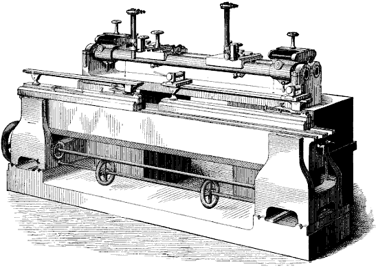
Fig. 1348.
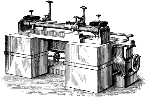
Fig. 1349.
Fig. 1348 is a front, and Fig. 1349 a rear view of the machine, whose details of construction are more clearly shown in the enlarged views, Fig. 1350 and 1352.
Large image (69 kB).
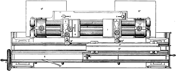
Fig. 1350.
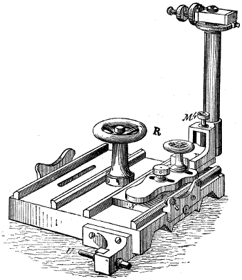
Fig. 1351.
Large image (74 kB).
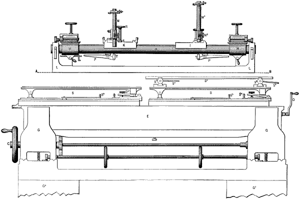
Fig. 1352.
Fig. 1350 is a top view, and Fig. 1352 a front view, the upper part of the machine being lifted up for clearness of illustration. x, x, are the cylindrical guides, upon which are the carriages i, k, for the microscopes. The construction of these carriages is more fully seen in Fig. 1351, which represents carriage k. It is provided with a hand-wheel r, operating a pinion in a rack (shown at t in the plan view figure of the machine) and affording means to traverse the carriage along the cylindrical guides. The microscope may be adjusted virtually by the screw m4. The base upon which the microscope stands is adjustable upon a plate n, by means of the two slots and binding screws shown, and the plate n fits in a slideway running across the carriage. u is one of the stops used in making end measurements, the other being fixed upon the frame of the machine at v in the plan view, Fig. 1350. The micrometric arrangement for the microscope is shown more clearly in Fig. 1353. The screw b holds the box in position, the edge of the circular base on which it sits being graduated, so that the position of m may be easily read. In the frame m is a piece of glass having ruled upon it the crossed lines, or in place of this a frame may be used, having in it crossed spider web lines. These lines are so arranged as to be exactly in focus of the upper glass of the microscope, this adjustment being made by means of the screw s. The lines upon the bar are in the focus of the lower glass; hence, both sets of lines can be seen simultaneously, and by suitable adjustment of the microscope can be brought to coincide.
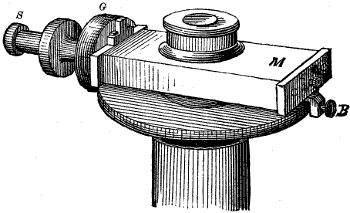
Fig. 1353.
Beneath the cylindrical guides, and supported by the rack t that runs between and beneath them, are the levers p, in Fig. 1352, upon which weights may be placed to take up the flexure or sag of the cylindrical guides.
In Fig. 1352, h, h, are heads that may be fixed to the cylindrical guides at any required point, and contain metallic stops, against which corresponding stops on the microscope carriages may abut, to limit and determine the amount to which these carriages may be moved along the cylindrical guides.
The pressure of contact between the carriage and the fixed stops is found to be sufficiently uniform or constant if the carriage is brought up to the stops (by means of the hand-wheel r, Fig. 1351) several times, and a microscope reading taken for each time of contact. But this pressure of contact may be made uniform or constant for all readings by means of an electric current applied to the carriage through the metallic stops on heads h, h, and those on the carriage.
We have now to describe the devices for supporting the work and adjusting it beneath the microscopes.
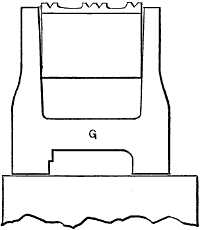
Fig. 1354.
Referring, then, to Fig. 1352, e is a bed or frame that may be raised or lowered by means of the hand-wheel c, so as to bring the plate s (on which rests the bar whose line measure is to be compared) within range of the microscopes. The upper face of e is provided with raised V slideways, which are more clearly seen in the end view of this part of the machine shown in Fig. 1354. Upon these raised Vs are the devices for adjusting the height of the eccentric rollers s3, upon which the bars to be tested are laid, s2 representing one of these bars. To adjust the bars in focus under the microscope, these eccentric rollers are revolved by means of levers s4. At s5 is a device for giving to the table a slight degree of longitudinal movement in the base plate that rests upon the raised Vs; on the upper face of e and at s6 is a mechanism for adjusting the height of that end of the plate s. The base plate may be moved along the raised Vs of e by the hand-wheel d.
To test whether the cylindrical guides are deflected by their own weight or are level, a trough of mercury may be set upon the eccentric rollers s3, Fig. 1352, and the fine particles of dust on its surface may be brought into focus in the microscope, whose carriage may then be traversed to various positions along the cylindrical guides, and if these dust particles remain in focus it is proof that the guides are level with the mercury surface.
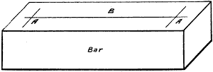
Fig. 1355.
The methods of using the machine are as follows: The standard bar has marked upon its upper face (which is made as true as possible and highly polished) a line b (Fig. 1355), which is called the horizontal line, and is necessary in order to set the bar parallel to the cylindrical guides of the machine. The lines a, a, are those defining the measurement as a yard, a foot, or whatever the case may be, and these are called the vertical lines or lines of measurement. Now, suppose we require to test a bar with the standard and the lines on its face are marked to correspond to those on the standard.
The first operation will be to set the standard bar on the eccentric rollers s3 in Fig. 1352, and it and the microscopes are so adjusted that the spider web lines in the microscope exactly intersect the lines a and b on the standard, when the microscope carriage abuts against the heads h, Fig. 1352. The standard bar is then replaced by the bar to be tested, which is adjusted without altering the microscope adjustment or the heads h, and if the spider web lines in the microscope exactly coincide with and intersect the lines a and b, the copy corresponds to the standard. But if they do not coincide, then the amount of error may be found by the micrometer wheel g, Fig. 1353.
In this test the carriage is moved up against the stops h several times, and several readings or tests are made, so as to see that the force of the contact of the carriage against the stops h is uniform at each test, and if any variation is found, the average of a number of readings is taken. It is found, however, that with practice the carriage may be moved against the head h by means of the hand-wheel with such an equal degree of force that an error of not more than one fifty-thousandth of an inch is induced. It is found, however, that if too much time is occupied in this test, the heat of the operator’s body will affect the temperature of the bars, and therefore expand them and vitiate the comparison. But in this connection it may be noted that if a bar is at a temperature of 40°, and is placed in an ice bath, it does not show any contraction in less than one minute, and that when it does so, the contraction is irregular, taking place in sudden movements or impulses.
Professor Rogers’ methods of testing end measures are as follows: To compare a line with an end measure, a standard bar is set upon the machine, its horizontal and vertical lines being adjusted true to the cylindrical guides by the means already described, and the microscope carriage is so adjusted that the spider web lines of the microscope coincide with the horizontal and vertical lines marked on the standard, while at the same time the stop (u, Fig. 1350) on the carriage k has contact with the fixed stop (v, Fig. 1350.) Carriage k is then moved along the cylindrical guides so as to admit the bar (whose end measure is to be compared with the lines on the standard) between the two stops, and if, with the bar touched by both stops u and v, the microscope spider lines intersect the vertical and horizontal line on the standard bar, then the end measure corresponds to the line measure; whereas, if such is not the case, the amount of error may be found by noting how much movement of the micrometer wheel of the microscope is required to cause the lines to intersect.
It is obvious that in this test, if the cylindrical guides had a horizontal curvature, the test would not be perfect.
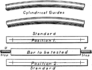
Fig. 1356.
The Horizontal Curvature.—The copy or bar to be tested may be set between the stops, and the standard bar may be placed on one side of it, as in Fig. 1356, and the test be made as already described. It is then set the same distance from the bar to be tested, but on the other side of it, as in figure, and again adjusted for position and tested, and if the readings on the standard bar are the same in both tests, it is proof that the measurements are correct.
Suppose, for example, that the cylindrical guides were curved as in Fig. 1356, it is evident that the vertical lines would appear closer together on the standard bar when in the first position than when in the second position.
In the Rogers machine the amount of error due to curvature in the cylindrical guides in this direction is found to be about 1⁄5000 part of an inch in 39 inches, corresponding to a radius of curvature of five miles.

Fig. 1357.
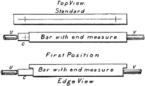
Fig. 1358.
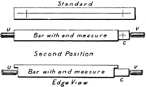
Fig. 1359.
Another method of testing an end with a line measure is as follows: The bar to be measured is shaped as in Fig. 1357, the end measurement being taken at a, and the projection b at each end serving to preserve the end surfaces a from damage. The standard bar is then set upon the machine and its horizontal and vertical lines adjusted in position as before described. In connection with this adjustment, however, the bar to be tested is set as in Fig. 1358; c being a block of metal (having marked centrally upon it horizontal and vertical lines), placed between the bar and the fixed stop u, its vertical line being in line with the vertical line on the standard. This adjustment being made, the block c is removed and placed at the other end of the bar, as shown in Fig. 1359, when, if the end measure on the bar corresponds with the line measure on the standard, the vertical line at the other end of the standard will correspond with the vertical line on block c.
To prove that the vertical line is exactly equidistant from each end of the block c, all that is necessary is to place it between the bar and the fixed stop u, Fig. 1350, adjust the microscope to it and then turn it end for end, and if its vertical line is still in line with the spider web of the microscope it is proof that it is central on the block, while if it is not central the necessary correction may be made. It is obvious that it is no matter what the length of c may be so long as its vertical line is central in its length.
In this process the coincidence of the vertical lines on the standard and on the piece c are employed to test the end measure on the bar with the line measure on the standard.
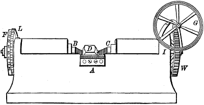
Fig. 1360.—General View.
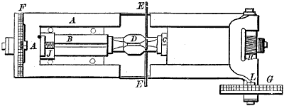
Fig. 1361.—Plan.
Figs. 1360 and 1361 represent the Whitworth Millionth Measuring Machine, in which the measurement is taken by the readings of an index wheel, and the contact is determined from the sense of touch and the force of gravity.
It is obvious that in measuring very minute fractions of an inch one of the main difficulties that arise is that the pressure of contact between the measuring machine and the surfaces measured must be maintained constant in degree, because any difference in this pressure vitiates the accuracy of the measurement. This pressure should also be as small as is consistent with the assurance that contact actually exists, otherwise the parts will spring, and this would again impair the accuracy of the measurement.
If the degree of contact is regulated by devices connected with the moving mechanism of the machine it is indirect, and may vary from causes acting upon that mechanism. But if it is regulated between the work and the moving piece that measures it, nothing remains but to devise some means of making its degree or amount constant for all measurements; so that if a duplicate requires to be compared with a standard, the latter may first be measured and the duplicate be afterwards measured for comparison.
All that is essential is that the two be touched with an equal degree of contact, and the most ingenious and delicate method yet devised to accomplish this result is that in the Whitworth machine, whose construction is as follows:—
In a box frame a, is provided a slide-way for two square bars, b, c, which are operated by micrometer screws, one of which is shown at j (the cap over b being removed to expose b and j to view). The bars b, c, are made truly square, and each side a true plane. The groove or slide-way in which they traverse is made with its two sides true planes at a right angle to each other; so that the bars in approaching or receding from each other move with their axes in a straight line. At the two ends of the frame the micrometer screws are afforded journal bearings. The ends of the bars b, c, are true planes at a right angle to the axes of b, c. Bar b is operated as follows: Its operating screw j has a thread of 1⁄20 inch pitch; or in other words, there are twenty threads in an inch of its length. It is rotated by the hand-wheel f, whose rim-face is graduated by 250 equidistant lines of division. Moving f through a distance equal to that between, or from centre to centre of its lines of division, moves b through a distance equal to one five-thousandth part of an inch.
The screw in head i for operating bar c also has a pitch of 1⁄20 inch (or twenty threads in an inch of its length), and is driven by a worm-wheel w, having 200 teeth. This worm-wheel w is driven by a worm or tangent-screw h, having upon its stem a graduated wheel g, having 250 equidistant lines marked upon the face of its rim.
Suppose, then, that wheel g be moved through a distance equal to that between its lines of division, that is 1⁄250th of a rotation, then the worm h will move through 1⁄250th of a rotation, and the worm-wheel on the micrometer screw will be rotated 1⁄250th part of its pitch expressed in inches; because a full rotation of g would move the worm one rotation, and thus would move the worm-wheel on the screw one tooth only, whereas it has 200 teeth in its circumference; hence it is obvious that moving graduated wheel g, through a distance equal to one of its rim divisions will move the bar c the one-millionth of an inch; because:
Pitch of thread Rotation of worm‑wheel Rotation of graduated wheel
1⁄20 inch × 1⁄200 × 1⁄250 = 1⁄1000000
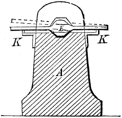
Fig. 1362.
Fixed pointers, as k, Fig. 1362, enable the amount of movement or rotation of the respective wheels f, g, to be read.
A peculiarly valuable feature of this machine is the means by which it enables an equal pressure of contact to be had upon the standards, and the duplicates to be tested therewith. This feature is of great importance where fine and accurate measurements are to be taken. The means of accomplishing this end are as follows:—
In the figures, d is a piece in position to be measured, and between it and the bar c is a feeler consisting of a small flat strip of steel, e e, having parallel sides, which are true planes.
When the pressure of contact upon this piece e e is such that if one end be supported independently the other will just be supported by friction, and yet may be easily moved between d and c by a touch of the finger, the adjustment is complete. At the sides of the frame a are two small brackets, shown at k, in the end view, Fig. 1362, e e being shown in full lines resting upon them, and in dotted lines with one end suspended. The contact-adjustment may thus be made with much greater delicacy and accuracy than in those machines in which the friction is applied to the graduated wheel-rim, because in the latter case, whatever friction there may be is multiplied by the difference in the amount of movement of the graduated rim and that of the bar touching the work.
All that is necessary in the Whitworth machine is to let e e be easy of movement under a slight touch, though capable of suspending one end by friction, and to note the position of the lines of graduation on c with reference to its pointer. By reason of having two operative bars, b, c, that which can be most readily moved may be operated to admit the piece or to adjust the bars to suit the length of the work, while that having the finer adjustive motion, as c, may be used for the final measuring only, thus preserving it from use, and therefore from wear as much as possible; or coarser measurements may be made with one bar, and more minute ones with the other.
So delicate and accurate are the measurements taken with this machine, that it is stated by C. P. B. Shelley, C.E., in his “Workshop Appliances,” that if well protected from changes of temperature and from dust, a momentary contact of the finger-nail will suffice to produce a measurable expansion by reason of the heat imparted to the metal. In an iron bar 36 inches long, a space equal to half a division on the wheel g having been rendered distinctly measurable by it, this space indicating an amount of expansion in the 36-inch bar equals the one two-millionth part of an inch!
The following figures, which are taken from Mechanics, represent a measuring machine made by the Betts Machine Company, of Wilmington, Delaware.
Large image (65 kB).
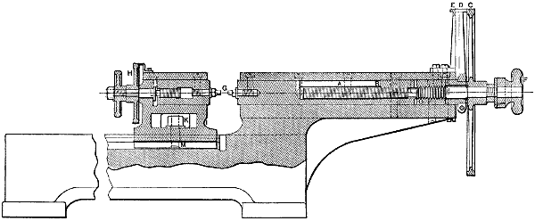
Fig. 1363.
Fig. 1363 shows a vertical section through the length of the machine, which consists of a bed carrying a fixed and an adjustable head, the fixed head carrying the measuring screw and vernier while the adjustable one carries a screw for approximate adjustment in setting the points of the standard bars.
These screws have a pitch of ten threads per inch, and the range of the measuring screw has a range of 4 inches, and the machine is furnished with firm standard steel bars (4-inch, 6-inch, 18-inch, and 24-inch). The measuring points of the screws are of hardened steel, secured axially in line with the screws, and of two forms, with spherical and flat points, one set of each being used at a time. The larger wheel c is indexed to 1000 divisions, each division representing the ten-thousandth of an inch at the points; the smaller wheel has 100 divisions, each representing the one-thousandth part of an inch at the points. Beside, and almost in contact with, the larger wheel is a movable or adjustable pointer e, upon which the error of the screw is indexed for each inch of its length; the screw error is of the utmost importance when positive results are desired. The screw is immersed in oil to maintain a uniform temperature throughout its length, and to avoid particles of dust accumulating on its surface.
As stated above, the readings are indexed to the ten-thousandth part of an inch, but variations to the hundred-thousandth part of an inch can be indicated. The machine will take in pieces to 24 inches in length, and to 4 inches in diameter. In measuring, the points are brought into easy contact and then expanded by turning the larger wheel, counting the revolutions or parts of revolutions to determine the distance between the points or the size of what is to be measured. The smaller machine is constructed so as to indicate by means of vernier attachment to the ten-thousandth part of an inch, and is of value in tool-rooms where standard and special tools are continually being prepared. By its use, gauges and other exact tools can be made, and at the same time keep gauges of all kinds to standard size by detecting wear or derangement. The machine consists of a frame with one fixed head; the other head is moved by a screw; on both heads are hardened steel points. As with the larger machine, the screw error is indicated in such a manner as to permit the operator to guard against reproducing its error in its work. These machines are used for making gauges, reamers, drills, mandrels, taps, and so on.
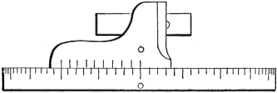
Fig. 1364.
The errors that may exist in the pitch of the measuring screw are taken into account as follows: The points of the measuring machine should be brought into light contact, the position of index-wheel, vernier, and the adjustable pointer which has the screw error indexed upon it should be as in Fig. 1364; that is, the zeros on index-wheel and vernier should be in exact line, the vernier covering half of the zero line on pointer. To measure 1⁄2 inch, for illustration, five complete revolutions of index-wheel should produce 1⁄2 inch, and would if we had a perfect screw, but the screw is not perfect, and we must add to the measurement already obtained one-half of the space, stamped upon corrective devise, 0-1. This space 0-1 represents the whole error in the screw from zero to 1 inch. The backlash of the screw should always be taken up.
The details of this machine are as follows:—
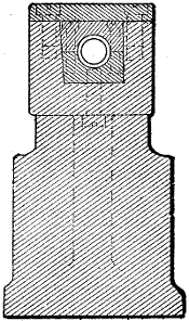
Fig. 1365.
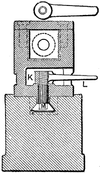
Fig. 1366.
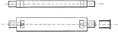
Fig. 1367.

Fig. 1368.
In Fig. 1363 the points g are those between which the measuring is done, and the slide held by the nut k in position is adjusted by means of inch bars to the distance to be measured; h, the hand-wheel for moving one point, and f the wheel which moves the other. Fig. 1366 is a cross section of the movable head through the nut k and stud m, by which the movable head is adjusted, and Fig. 1365 is a cross section through the fixed head. The bars used in setting the machine are shown in Fig. 1367, and in Fig. 1368 the points of the measuring screws are shown on a large scale. The other figures show various details of the machine and their method of construction. The vernier, it will be observed, is a double one. This is shown in Fig. 1364, and is so arranged that the zero is made movable in order to correct the errors of the screw itself. These errors are carefully investigated and a record made of each. Thus, in Fig. 1363 the arm e is graduated so as to show the true zero for different parts of the screw; d can then be adjusted to a correct reading, and the divisions on the large wheel will then be correct to an exceedingly small fraction. This method of construction enables the machine to be used for indicating very minute variations of length.
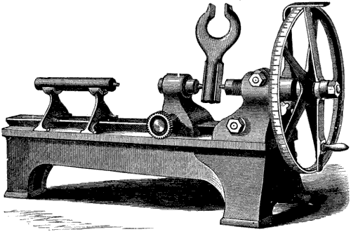
Fig. 1369.
In Fig. 1369 is shown a measuring machine designed by Professor John E. Sweet, late of Cornell University. The bed of the machine rests on three feet, so that the amount of support at each leg may remain the same, whether the surface upon which it rests be a true plane or otherwise. This bed carries a headstock and a tailstock similar to a lathe. The tailstock carries a stationary feeler, and the headstock a movable one, operated horizontally by a screw passing through a nut provided in the headstock, the axial lines of the two feelers being parallel and in the same plane. The diameters of the two feelers are equal at the ends, so that each feeler shall present the same amount of end area to the work. The nut for the screw operating the headstock feeler is of the same length as the screw itself, so that the wear of the screw shall be equalized as near as possible from end to end, and not be the most at and near the middle of its length, as occurs when the thread on the screw is longer than that in the nut.
The pitch of the thread on the screw is 16 threads in an inch of length, hence one revolution of the screw advances the feeler 1⁄16 inch. The screw carries a wheel whose circumference is marked or graduated by 625 equidistant lines of division. If, therefore, this wheel be moved through a part of a rotation equal to one of these divisions, the feeler will move a distance equal to 1⁄625 of the 1⁄16th of an inch, which is the ten thousandth part of an inch, and as the bed of the machine is long enough to permit the feelers to be placed 12 inches apart, the machine will measure from zero to 12 inches by the ten-thousandth of an inch.
To assist the eye in reading the lines of division, each tenth line is marked longer than the rest, and every hundredth, still longer. The pitch of the screw being 16 threads to an inch enables the feeler to be advanced or retired (according to the direction of the rotation of the wheel) a sixteenth inch by a simple rotation of the wheel, an eighth inch by two wheel rotations, a thirty-second inch by a quarter rotation, and so on; and this renders the use of that machine very simple for testing the accuracy of caliper gauges, that are graduated to 1⁄8, 1⁄16, 1⁄32, 1⁄64th inch, and so on, such a gauge being shown (in the cut) between the feelers.
The bar or arm shown fixed to the headstock and passing over the circumference of the wheel at the top affords a fixed line or point wherefrom to note the motion of the wheel, or in other words, the number of graduations it moves through at each wheel movement. It is evident that in a machine of this kind it is essential that the work to be measured have contact with the feelers, but that it shall not be sufficient to cause a strain or force that will spring or deflect either the work itself (if it be slight) or the parts of the machine. It is also essential that at excessive measurements the feelers shall touch the work with the same amount of force. The manner of attaining this end in Professor Sweet’s machine is as follows: Upon the same shaft as the wheel is an arm having contact at both ends with the edge of the wheel rim whose face is graduated. This arm is free to rotate upon the shaft carrying the graduated wheel, which it therefore drives by multiple friction on its edges at diametrically opposite points; by means of a nut the degree of this friction may be adjusted so as to be just sufficient to drive the wheel without slip when the wheel is moved slowly. So long, then, as the feelers have no contact with the piece to be measured, the arm will drive the graduated wheel, but when contact does take place the wheel will be arrested and the arm will slip. The greatest accuracy will therefore be obtained if the arm be moved at an equal speed for all measurements.
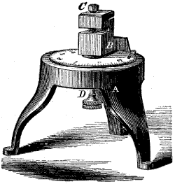
Fig. 1370.
Fig. 1370 represents a Brown and Sharpe measuring machine for sheet metal. It consists of a stand a with a slotted upright having an adjusting screw c above, and a screw d, with a milled head and carrying a dial, passing through its lower part. One turn of the screw, whose threads are 1⁄10th inch apart, causes one rotation of the dial, the edge of which is divided into one hundred parts, enabling measurements to be made to thousandths of an inch. The sheet-metal to be gauged is inserted in the slot of the upright. The adjusting-screw is set so that when the points of the two screws meet, the zero of the dial shall be opposite an index or pointer which shows the number of divisions passed over, and is firmly secured by a set-screw.
Next in importance to line and end measurements is the accurate division of the circle, to accomplish which the following means have been taken.
What is known as “Troughton’s” method (which was invented by Edward Troughton about 1809) is as follows: A disk or circle of 4 feet radius was accurately turned, both on its face and its inner and outer edges. A roller was next provided of such diameter that it revolved sixteen times on its own axis, while rolling once round the outer edge of the circle. This roller was pivoted in a framework which could be slid freely, yet tightly, along the circle, the roller meanwhile revolving by frictional contact on the outer edge. The roller was also, after having been properly adjusted as to size, divided as accurately as possible into sixteen equal parts by lines parallel to its axis. While the frame carrying the roller was moved once round along the circle, the points of contact of the roller divisions with the circle were accurately observed by two microscopes attached to the frames, one of which commanded the ring on the circle near its edge, which was to receive the divisions, and the other viewed the roller divisions. The exact points of contact thus ascertained were marked with faint dots, and the meridian circle thereby divided into 256 very nearly equal parts.
The next part of the operation was to find out and tabulate the errors of these dots, which are called apparent errors, because the error of each dot was ascertained on the supposition that all its neighbors were correct. For this purpose two microscopes, which we shall call a and c, were taken with cross-wires and micrometer adjustments, consisting of a screw and head divided into 100 divisions, 50 of which read in the one and 50 in the opposite direction. These microscopes, a and b, were fixed so that their cross-wires respectively bisected the dots 0 and 128, which were supposed to be diametrically opposite. The circle was now turned half way round on its axis, so that dot 128 coincided with the wire of a, and should dot 0 be found to coincide with b, then the dots were sure to be 180° apart. If not, the cross-wire of b was moved till it coincided with the dot 0 and the number of divisions of micrometer head noted. Half this number gave clearly the error of dot 128 and was tabulated plus or minus according as the arcual distance between 0 and 128 was found to exceed or fall short of the removing part of the circumference. The microscope b was now shifted, a remaining opposite dot 0 as before, till its wire bisected dot 64, and by giving the circle one-quarter of a turn on its axis, the difference of the arcs between dots 0 and 64, and between 64 and 128 was obtained. The half of this distance gave the apparent error of dot 64, which was tabulated with its proper sign. With the microscope a still in the same position, the error of dot 192 was obtained, and in the same way, by shifting b to dot 32, the errors of dots 32, 96, 160 and 224 were successively ascertained. By proceeding in this way the apparent errors of all the 256 dots were tabulated.
In order to make this method fully understood, we have prepared the accompanying diagrams, which clearly show the plan pursued.
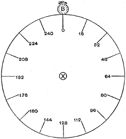
Fig. 1371.
Fig. 1371 illustrates the plan of dividing the large circle by means of the roller b.
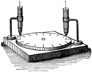
Fig. 1372.
Fig. 1372 shows the general adjustment of the microscope for the purpose of proving the correctness of the divisions.
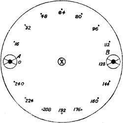
Fig. 1373.
Fig. 1373 shows the location of the microscope over the points 0 and 128.
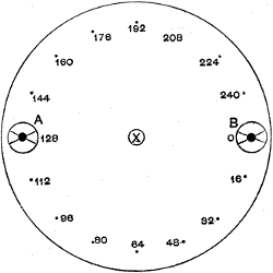
Fig. 1374.
Fig. 1374 shows the circle turned half-way round, the points 0 and 128 coinciding with the cross threads of the microscope.
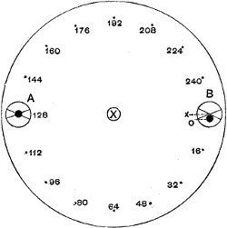
Fig. 1375.
Fig. 1375 shows a similar reading, in which the points do not coincide with the cross threads of the microscope.
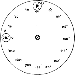
Fig. 1376.
Fig. 1376 shows the microscope adjusted for testing by turning the circle a quarter revolution.
Large image (248 kB).
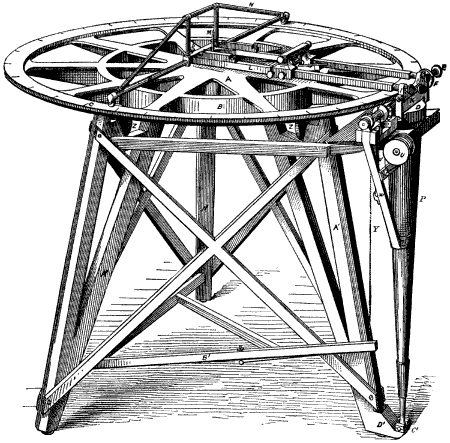
Fig. 1377.
Fig. 1377 represents one of the later forms of Ramsden’s dividing engine.[21] It consists first of a three-legged table, braced so as to be exceedingly stiff. Upon this is placed a horizontal wheel with deep webs, and a flat rim. The webs stiffen the wheel as much as possible, and one of these webs, which runs round the wheel about half-way between the centre and the circumference, rests upon a series of rollers which support it, and prevent, as far as possible, the arms from being deflected by their own weight. An outer circle, which receives the graduation, is laid upon the rim of the wheel and secured in place. The edge of this circle is made concave. A very fine screw, mounted in boxes and supported independently, is then brought against this hollow edge, and, being pressed against it, the screw, when revolved, of course cuts a series of teeth in the circumference, and this tooth-cutting, facilitated by having the screw threads made with teeth, was continued until perfect V-shaped teeth were cut all around the edge of the wheel. This Mr. Ramsden calls ratching the wheel. The number of teeth, the circumference of the wheel, and the pitch of the screw were all carefully adjusted, so that by using 2160 teeth, six revolutions of the screw would move the wheel the space of 1°. When this work was finished, and the adjustment had been made as perfect as possible, a screw without teeth—that is, one in which the thread was perfect—was put in the place of that which had cut the teeth from the wheel, and the machine was perfected. The wheel a b c in the drawings is made of bell metal, and turns in a socket under the stand, which prevents the wheel from sliding from the supporting or friction rolls z, z. The centre r, working against the spindle m, is made so as to fit instruments of various sizes. The large wheel has a radius of 45 inches, and has 10 arms. The ring b is 24 inches in diameter by 3 inches deep. The ring c is of very fine brass, fitting exactly on the circumference of the wheel, and fastened by screws, which, after being screwed home, were well riveted. Great care was taken in making the centre on which the wheel worked exceedingly true and perfect, and in making the socket for the wheel fit as exactly as possible. The revolving mechanism is all carried on the pillar p, resting on the socket c′. We may state here that the machine, as shown in the engravings, now in the possession of the Stevens Institute, is in some respects slightly improved on that shown in the original drawings published in “Rees’ Cyclopædia” in 1819. After the wheel was put on its stand, and the pulleys in place, the instrument was ready for the turning mechanism. The upper part of this pillar p carries the framework in which the traversing screw revolves.
Large image (197 kB).
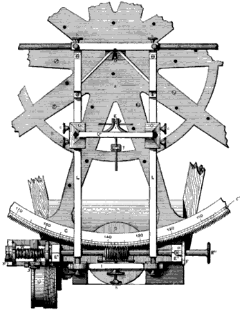
Fig. 1378.
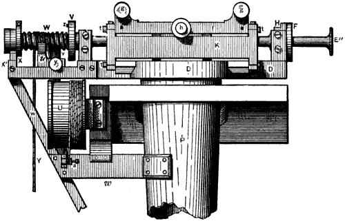
Fig. 1379.
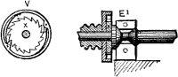
Fig. 1380.
In Fig. 1378 d is the head of this pillar, p the screw which turns the wheel. e1 e1 are the boxes, which are made conical so as to prevent any shake and to hold the screw firmly. Circles of brass, f and v, are placed on the arbor of the screw, and as their circumference is divided into 60 parts, each division consequently amounts to a motion of the wheel of 10 seconds, and 60 of them will equal 1 minute. Revolution is given to the screw by means of the treadle b′ and the cord y, which runs over the guiding screw w, Fig. 1379, and is finally attached to the box u. A spring enclosed in the box u causes it to revolve, and winds up the slack of the cord whenever the treadle is relieved. In the original drawing the head of the pillar p was carried in a parallel slip in the piece surrounding its head. The construction as shown in Fig. 1379 is somewhat different. The result attained, however, is identical, and the spindles and attachments are held so as to have no lateral motion. The wheels v and x have stops upon them, so arranged that the screw may be turned definitely to a given point and stopped. These wheels are at the opposite ends of the screw w. A detail of one of them is shown at v in Fig. 1380, where x is the ratchet-wheel. This figure also illustrates the construction of the bearings for the screw arbor. We have not space to explain the method by which the perfection of the screw was obtained, nor to discuss the means by which was obtained the success of so eliminating the errors as to make the division of the instrument more perfect than anything which had been attempted previously. Success, however, was obtained, and by means of the first or tooth-cutting screw the teeth were brought to such a considerable uniformity that, together with the fact that the screw took hold of a number of teeth at one time, most of the errors which would have been expected from this method of operation were eliminated. The method of ruling lines upon the instrument was most ingenious. The frame l l, is connected to the head d, of the pillar p in front, by the clamps i and k, and to the centre m by the block r. A frame n n stiffens the back. The blocks o, o on the frame q′ are secured to the frame l l, by set-screws c, c.
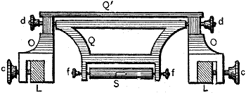
Fig. 1381.
Fig. 1381 shows a side view of the frame q′, which it is seen carries a V-shaped piece q, which in turn carries another V-shaped piece s, Fig. 1378. The piece q is supported on pointed screws d, d, and the piece s is supported on two similar screws f, f. The point of this piece s carries the cutting tool e, Fig. 1378. Of course s can move only in a radial line from the centre m towards the circumference. If the sextant, octant, or other instrument be fastened to the large wheel a, with its centre at m, and the large wheel be rotated by the screw, all lines drawn upon it by e will be radial, and the distances apart will be governed by the number of turns made by the screw. This improvement, we think, was originated by Mr. Ramsden, and was a very great advance over the old method of the straight-edge, and has been used in some of the Government comparators and dividing engines. The following is Mr. Ramsden’s own description of the graduation of the machine, and of his method of operating it. It shows the extreme care which he took in correcting the mechanical errors in the construction:—
“From a very exact centre a circle was described on the ring c, about 4⁄10 inch within where the bottom of the teeth would come. This circle was divided with the greatest exactness I was capable of, first into five parts, and each of these into three. These parts were then bisected four times; that is to say, supposing the whole circumference of the wheel to contain 2160 teeth, this being divided into five parts, and these again divided into three parts, each third part would contain 144, and this space, bisected four times, would give 72, 36, 18, 9; therefore, each of the last divisions would contain 9 teeth. But, as I was apprehensive some error might arise from quinquesection and trisection, in order to examine the accuracy of the divisions, I described another circle on the ring c, Fig. 1378, 1⁄10 inch within the first, and divided it by continual bisection, as 2160, 1080, 540, 270, 135, 671⁄2, 333⁄4, and, as the fixed wire (to be described presently) crossed both the circles, I could examine their agreement at every 135 revolutions (after ratching could examine it at every 333⁄4); but not finding any sensible difference between the two sets of divisions, I, for ratching, made choice of the former, and, as the coincidence of the fixed wire with an intersection could be more exactly determined with a dot or division, I therefore made use of intersections on both sides, before described.
“The arms of the frame l, Fig. 1381, were connected by a thin piece of brass, 3⁄4 inch broad, having a hole in the middle 4⁄10 inch in diameter; across this hole a silver wire was fixed, exactly in a line to the centre of the wheel; the coincidence of this wire with the intersections was examined by a lens of 1⁄10 inch focus, fixed in a tube which was attached to one of the arms l. Now (a handle or winch being fixed on the end of the screw) the division marked 10 on the circle f was set to its index, and, by means of a clamp and adjusting-screw for that purpose, the intersection marked i on the circle c′ was set exactly to coincide with the fixed wire. The screw was then carefully pressed against the circumference of the wheel by turning the finger-screw h; then, removing the clamp, I turned the screw by its handle nine revolutions, till the intersection marked 240 came nearly to the wire. Then, turning the finger-screw h, I released the screw from the wheel, and turned the wheel back till the intersection marked 2 exactly coincided with the wire, and by means of the clamp before mentioned, the division 10 on the circle being set to its index, the screw was pressed against the edges of the wheel by the finger-screw h, the clamps were removed, and the screw turned nine revolutions, till the intersection marked i nearly coincided with the fixed wire; the screw was released from the wheel by turning finger-screw h as before, the wheel was turned back till intersection marked 3 coincided with the fixed wire; the division 10 in the circle being set to its index, the screw was pressed against the wheel as before, and the screw turned nine revolutions, till intersection 2 was nearly coincident with the fixed wire, and the screw released, and I proceeded in this manner till the teeth were marked round the whole circumference of the wheel. This was repeated three times round to make the impressions deeper. I then ratched the wheel round continuously in the same direction, without ever disengaging the screw, and, in ratching the wheel about 300 times round, the teeth were finished.
“Now, it is evident that if the circumference of the wheel was even one tooth, or ten minutes, greater than the screw would require, this error would, in the first instance, be reduced by 1⁄240 part of a revolution, or two seconds and a half, and these errors or inequalities of the teeth were equally distributed round the wheel at the distance of nine teeth from each other. Now, as the screw in ratching had continual hold of several teeth at the same time and thus constantly changing, the above-mentioned irregularities soon corrected themselves, and the teeth were reduced to a perfect equality. The piece of brass which carried the wire was now taken away, and the cutting-screw was also removed, and a plain one put in its place. At one end of the screw arbor, or mandrel was a small brass circle f, having its edge divided into 60 parts, numbered at every sixth division, as before mentioned. On the other end of the screw is a ratchet-wheel v (x, Fig. 1380) having 60 teeth, covered by the hollow circle (v, Fig. 1380), which carries two clicks that catch upon opposite sides of the ratchet-wheel. When the screw is to be moved forward, the cylinder w turns on a strong steel arbor e′′, which passes through the piece x′; this piece, for greater firmness, is attached to the screw-frame by the braces w. A spiral groove or thread is cut upon the outside of the cylinder w, which serves both for holding the string and also giving motion to the lever i on its centre, by means of a steel tooth v, that works between the threads of the spiral. To the lever is attached a strong steel pin m, on which a brass socket turns; this socket passes through a slit in the piece u, and may be tightened in any part of the slit by the finger-nut y. This piece serves to regulate the number of revolutions of the screw for each tread of the treadle b′.”
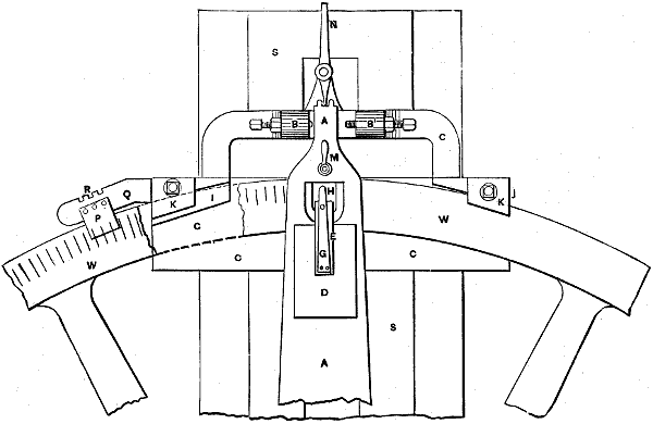
Fig. 1382.
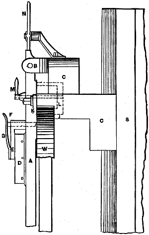
Fig. 1383.
Figs. 1382, 1383, and 1384 represent a method adopted to divide a circle by the Pratt and Whitney Company. The principle of the device is to enable the wheel to be marked, to be moved through a part of a revolution equal to the length of a division, and to test the accuracy of the divisions by the coincidence of the line first marked with that marked last when the wheel has been moved as many times as it is to contain divisions. By this means any error in the division multiplies, so that the last division marked will exhibit it multiplied by as many times as there are divisions in the whole wheel. The accuracy of this method, so long as variations of temperature are avoided, both in the marking and the drilling of the wheel, appears to be beyond question. In the figures, w represents a segment of the wheel to be divided, and c what may be termed a dividing chuck. The wheel is mounted on an arbor in a gear-cutting machine. On the hub of the wheel (which has been turned up for the purpose) there is fitted, to a close working fit, a bore at the end of an arm, the other end of the arm being denoted by a in the figures. The dividing chuck is fitted to the slide s of the gear-cutting machine, and is of the following construction.
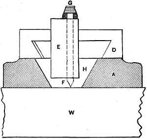
Fig. 1384.
Between two lugs, b and b′, it receives the end of arm a. These lugs are provided with set-screws, the distance between the ends of which regulate the amount of movement of the end of arm a. Upon a is the slide d, carrying the piece e, in which is the marking tool f, the latter being lifted by a spring g, and, therefore, having no contact with the wheel surface until the spring is depressed. h is an opening through the arm a to permit the marking tool f to meet the wheel face, as shown in Fig. 1384, which is an end view of the slide showing the arm a in section. The face of the wheel rests upon the chuck on each side of the arm at the points i, j, and may be clamped thereto by the clamps k. The arm may be clamped to the wheel by the clamp shown dotted in at l, the bolt passing up and through the screw handle m. n is simply a lever with which to move the arm a, or arm a and the wheel. Suppose all the parts to be in the position shown in the cuts, the clamps being all tightened up, the slide d may be moved forward towards k, while the spring is depressed, and f will mark a line upon the wheel. The handle m may then be released and arm a moved until it touches the set-screw in b′, when m may be tightened and another line marked. Clamps k are then tightened, and the wheel, with the arm a fast to it, moved back to the position shown in the cut, when the clamps may be tightened again and another line marked, the process being continued all round the wheel. To detect and enable the correction of any discoverable error in a division, there is provided the plate p, having upon it three lines of division (which have been marked simultaneously with three of the lines marked on the wheel). This plate is supported by an arm or bracket q, on the rear edge of which are three notches r to hold a microscope, by means of which the lines on p may be compared with those on the wheel face, so that if any discrepancy should appear it may be determined which line is in error. The labor involved in the operation of marking a large wheel is very great. Suppose, for example, that a wheel has 200 lines of division, and that after going round the wheel as described it is found that the last division is 100th inch out; then in each division the error is the two-hundredth part of this 100th inch, and that is all the alteration that must be made in the distance between set-screws b and b′.
VOL. I. DIVIDING ENGINE AND MICROMETER. PLATE XV.
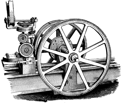
Fig. 1385.
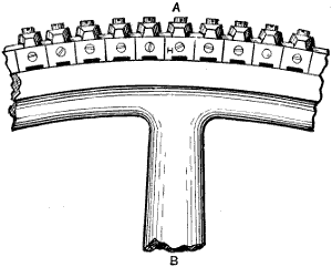
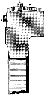
Fig. 1386. Fig. 1387.
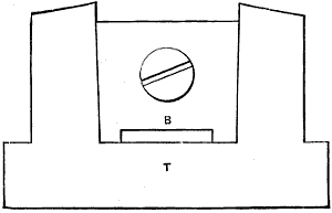
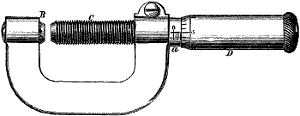
Fig. 1388. Fig. 1389.


Fig. 1390. Fig. 1391.
Figs. 1385 and 1386 represent a method of originating an index wheel, adopted by R. Hoe and Co., of New York City.
In this method the plan was adopted of fitting round a wheel 180 tapering blocks, which should form a complete and perfect circle. These blocks were to serve the same purpose as is ordinarily accomplished by holes perforated on the face of an index wheel. In their construction, means of correcting any errors that might be found, without the necessity of throwing away any portion of the work done, would also be provided. Further, this means would provide for taking up wear, should any occur in the course of time, and thus restore the original truth of the wheel.
Fig. 1385 of the engravings shows the originating wheel mounted upon a machine or cutting engine. Upon the opposite end of the shaft is the worm-wheel in the process of cutting. After the master worm-wheel has been thus prepared by means of the originating wheel, it is used upon the front end of the shaft, in the position now occupied by the originating wheel, and operated by a worm in the usual manner. Subdivisions are made by change wheels. The construction of the originating wheel will be understood by the smaller engravings.
Fig. 1386 is an enlarged section of a segment of the wheel, while Fig. 1387 is an edge view of this segment. Fig. 1388 is a view of one of the blocks employed in the construction of the wheel, drawn to full size.
In the rim of the originating wheel there was turned a shoulder, c, Fig. 1387, 5 feet in diameter. Upon this shoulder there were clamped 180 blocks, of the character shown in Fig. 1386, as indicated by the section, Fig. 1387. These blocks were secured to the face of the wheel d by screws e, and were held down to the shoulder by the screw and clamp g f, shown in Fig. 1387. (They are omitted in Fig. 1385 for clearness of illustration.) In the preparation of these blocks each was fitted to a template t, in Fig. 1388, and was provided with a recess b, to save trouble in fitting and to insure each block seating firmly on the shoulder c. The shoulder, after successive trials, was finally reduced to such a diameter that the last block exactly filled the space left for it when it was fully seated on the shoulder c. The wheel thus prepared was mounted on a Whitworth cutting engine, as shown in Fig. 1385. The general process of using this wheel is as follows: The blocks forming the periphery of the originating wheel are used in place of the holes ordinarily seen in the index plates. One of them is removed to receive a tongue, shown in the centre of Fig. 1385, which, exactly filling the opening or notch thus made, holds the wheel firmly in place. After a tooth has been cut in the master worm-wheel, shown at the back of Fig. 1385, the block in the edge of the originating wheel corresponding to the next tooth to be cut is removed. The tongue is withdrawn from the first notch, the wheel is revolved, and the tongue is inserted in the second position. The block first removed is then replaced, and the cutting proceeds as before. This operation is repeated until all the teeth in the master wheel have been cut. The space being a taper, the tongue holds the originating wheel more firmly than is possible by means of cylindrical pins fitting into holes. The number of blocks in the originating wheel being 180, the teeth cut in the master wheel may be 180 or some exact divisor of this number.
The advantages of this method of origination are quite evident. Since 180 blocks were made to fill the circle, the edges of each had 2° taper. This taper enabled the blocks to be fitted perfectly to the template, because any error in fit would be remedied by letting the block farther down into the template. Hence, it was possible to correct any error that was discovered without throwing the block away. Further, as the blocks themselves are removed to form a recess for locking the originating wheel in position while cutting the worm-wheel, the truth of the work is not subject to the errors that creep in when holes or notches require to be pierced in the originating wheel. Such errors arise from the heating due to the drilling or cutting, from the wear of the tools or from their guides, from soft or hard spots in the metal and other similar causes. To avoid any error from the heating due to the cut on the worm-wheel, in producing master wheels, Messrs. Hoe and Co. allowed the wheel to cool after each cut. The teeth were cut in the following order: The first three were cut at equidistant points in the circumference of the wheel. The next three also were at equidistant points, and midway between those first cut. This plan was continued until all the teeth were cut, thus making the expansion of the wheel from the heat as nearly equal as possible in all directions.
There is one feature in this plan that is of value. It is that a certain number of blocks, for example six, may be taken out at two or three different parts of the originating wheel and interchanged, thus affording a means of testing that does not exist in any other method of dividing.
The tools applied by the workmen to measure or to test work may be divided into classes.
1st. Those used to determine the actual size or dimension of the work, which may be properly termed measuring tools.
2nd. Those used as standards of a certain size, which may be termed gauges.
3rd. Those used to compare one dimension with another, as in the common calipers.
4th. Those used to transfer measurements or distances defined by lines.
5th. Those used to test the accuracy of plane or flat surfaces, or to test the alignment of one surface to another.
Referring to the first, their distinctive feature is that they give the actual dimensions of the piece, whether it be of the required dimension or not.
The second determine whether the piece tested is of correct size or not, but do not show what the amount of error is, if there be any.
The third show whatever error there may be, but do not define its amount; and the same is true of the fifth and sixth.
Fig. 1389 represents a micrometer caliper for taking minute end measurements. This instrument is capable of being set to a standard measurement or of giving the actual size of a piece, and is therefore strictly speaking a combined measuring tool and a gauge. The U-shaped body of the instrument is provided with a hub a, which is threaded to receive a screw c, the latter being in one piece with the stem d, which envelops for a certain distance the hub a. The thread of c has a pitch of 40 per inch; hence one revolution of d causes the screw to move endways 1⁄40 of an inch.
The vertical lines of division shown on the hub a are also 1⁄40 of an inch apart, hence the bevelled edge of the sleeve advances one of the divisions on a at each rotation.
This bevelled edge is divided into 25 equal divisions round its circumference, as denoted by the lines marked 5, 10, &c. If, then, d be rotated to an amount equal to one of its points of division, the screw will advance 1⁄25 of 1⁄40 of an inch. In the cut, for example, the line 5 on the sleeve coincides with the zero line which runs parallel to the axial line of the hub. Now suppose sleeve d to be rotated so that the next line of division on the bevelled edge of d comes opposite to the zero line, then 1⁄25 part of a revolution of d will have been made, and as a full revolution of d would advance the screw 1⁄40 of an inch, then 1⁄25 of a revolution will advance it 1⁄25 of 1⁄40 inch, which is 1⁄1000 inch.
The zero line being divided by lines of equal division into 40ths of an inch, then, as shown in the cut, the instrument is set to measure 3⁄40ths and 5⁄25ths of a fortieth.
It is to be observed that to obtain correct measurements the work must be held true with the face of the foot b, and the contact between the end of screw c and the work must be just barely perceptible, otherwise the pressure of the screw will cause the U-piece to bend and vitiate the accuracy of the measurement. Furthermore, if the screw be rotated under pressure upon the work, its end will wear and in time impair the accuracy of the instrument. To take up any wear that may occur, the foot-piece b is screwed through the hub, holding it so that it may be screwed through the hub to the amount of the wear.
To avoid wear as much as possible, the screws of instruments of this kind are sometimes hardened, and to correct the error of pitch induced in the hardening, each screw is carefully tested to find in what direction the pitch of the hardened thread has varied, and provision is made for the correction as follows:—
The zero line on the hub a stands, if the thread is true to pitch, parallel to the axis of the screw c, but if the pitch of the thread has become coarser from hardening, this zero line is marked at an angle, as shown in Fig. 1390, in which a a represents the axial line of the screw and b the zero line.
If the screw pitch becomes finer from hardening, the zero line is made at an angle in the opposite direction, as shown in Fig. 1391, the amount of the angle being that necessary to correct the error in the screw pitch. The philosophy of this is, that if the pitch has become coarser a less amount of movement of the screw is necessary, while if it has become finer an increased movement is necessary. It is obvious, also, that if the pitch of the thread should become coarser at one end and finer at the other the zero line may be curved to suit.
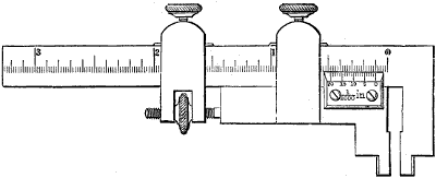
Fig. 1392.
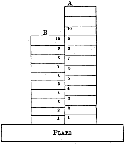
Fig. 1393.
Fig. 1392 represents a vernier caliper, in which the measurement is read by the coincidence of ruled lines upon the following principle. The vernier is a device for subdividing the readings of any equidistant lines of division. Its principle of action may be explained as follows: Suppose in Fig. 1393 a to be a rule or scale divided into inches and tenths of an inch, and b a vernier so divided that its ten equidistant divisions are equal to nine of the divisions on a; then the distance apart of the lines of division on a will be 1⁄10 inch; but, as the whole ten divisions on b measure less than an inch, by 1⁄10 inch, then each line of division is a tenth part of the lacking tenth less than 1⁄10 inch apart. Thus, were we to take a space equal to the 1⁄10 inch between 9 and 10 on a, and divide it into 10 equal parts (which would give ten parts each measuring 1⁄100th of an inch) and add one of said parts to each of the distances between the lines of division on b, then the whole of the lines on a would coincide with those on b. It becomes evident, then, that line 1 on b is 1⁄100 inch below line 1 on a, that line 2 on b is 2⁄100 inch below line 2 on a, line 3 on the vernier b is 3⁄100 inch below line 3 on the rule a, and so on, until we arrive at line 10 on the vernier, which is 10⁄100 or 1⁄10 inch below line 10 on a. Suppose, then, the rule or scale to rest vertically on a truly surfaced plate, and a piece of metal be placed beneath b, the thickness of the piece will be shown by which of the lines on b coincides with a line on a. For more minute divisions it is simply necessary to have more lines of division in a given length on a and b. Thus, if the rule be divided into inches and fiftieths, and the vernier is so divided that it has 20 equidistant lines of division to 19 lines on the rule, it will then lack one division, or 1⁄50 inch in 20⁄50 inch, each division on the vernier will then be the one-twentieth of a fiftieth too short, and as 1⁄20 of 1⁄50 is 1⁄1000, the instrument will read to one-thousandth of an inch.
Let it now be noted that, instead of making the lines of division closer together to obtain minute measurements, the same end may be obtained by making the vernier longer. For example, suppose it be required to measure to 1⁄2000 part of an inch, then, if the rule or scale be graduated to inches and fiftieths, and the vernier be graduated to have 40 equidistant lines of division, and 39 of the lines on the scale, the reading will be to the 1⁄2000 part of an inch. But, in any event, the whole of the readings on the vernier may be read, or will be passed through, while it is traversing a division equal to one of the divisions on the scale or rule.
In Fig. 1392 is shown a vernier caliper, in which the vernier is attached to and carried by a slide operating against the inside edge of the instrument. The bar is marked or graduated on one side by lines showing inches and fiftieths of an inch, with a vernier graduated to have 20 equidistant lines of division in 19 of the lines of division on the bar, and therefore measuring to the 1⁄1000th of an inch, while the other side is marked in millimètres with a vernier reading to 1⁄40th millimètre, there being also 20 lines of division on the vernier to 19 on the bar.
The inside surfaces of the feet or jaws are relieved from the bar to about the middle of their lengths, so as to confine the measuring surfaces to dimensions sufficiently small to insure accurate measurement, while large enough to provide a bearing area not subject to rapid wear. If the jaw surface had contact from the point to the bar, it would be impossible to employ the instrument upon a rectangular having a burr, or slight projection, on the edge. Again, by confining the bearing area to as small limits as consistent with the requirements of durability a smaller area of the measured work is covered, and the undulations of the same may be more minutely followed.
To maintain the surface of the movable jaw parallel with that of the bar-jaw, it is necessary that the edge of the slide carrying the vernier be maintained in proper contact with the edge of the instrument, which, while adjusting the vernier, should be accomplished as follows:—
The thumb-screw most distant from the vernier should be set up tight, so that that jaw is fixed in position. The other thumb-screw should be set so as to exert, on the small spring between its end and the edge of the bar, a pressure sufficient to bend that spring to almost its full limit, but not so as to let it grip the bar. The elasticity of the spring will then hold the edge of the vernier slide sufficiently firmly to the under edge of the bar to keep the jaw-surfaces parallel; to enable the correct adjustment of the vernier, and to permit the nut-wheel to move the slide without undue wear upon its thread, or undue wear between the edge of the slide and that of the bar, both of which evils will ensue if the thumb-screw nearest the vernier is screwed firmly home before the final measuring adjustment of the vernier is accomplished.
When the measurement is completed the second thumb-screw must be set home and the reading examined again, for correctness, to ascertain if tightening the screw has altered it, as it would be apt to do if the thumb-screw was adjusted too loose.
The jaws are tempered to resist wear, and are ground to a true plane surface, standing at a right angle to the body of the bar. The method of setting the instrument to a standard size is as follows:—
The zero line marked 0 on the vernier coincides with the line 0 on the bar when the jaws are close together; hence, when the 0 line on the vernier coincides with the inch line on the bar, the instrument is set to an inch between the jaws. When the line next to the 0 line on the vernier coincides with the line to the left of the inch line on the bar, the instrument is set to 11⁄1000 inches. If the vernier slide then be moved so that the second line on the vernier coincides with the second line, on the left of the inch on the bar, the instrument is set to 12⁄1000 inches, and so on, the measurement of inches and fiftieths of an inch being obtained by the coincidence of the zero line on the vernier with the necessary line on the bar, and the measurements of one-thousands being taken as described.
But if it is required to measure, or find the diameter of an existing piece of work, the method of measuring is as follows:—
The thumb-screws must be so adjusted as to allow the slide to move easily or freely upon the work without there being any play or looseness between the slide and the bar. The slide should be moved up so as to very nearly touch the work when the latter is placed between the jaws. The thumb-screw farthest from the vernier should then be screwed home, and the other thumb-screw operated to further depress the spring without causing it to lock upon the bar. The nut-wheel is then operated so that the jaws, placed squarely across the work, shall just have perceptible contact with it. (If the jaws were set to grip the work tight they would spring from the pressure, and impair the accuracy of the measurements.) The thumb-screw over the vernier may then be screwed home, and the adjustment of the instrument to the work again tried. If a correction should be found necessary, it is better to ease the pressure of the thumb-screw over the vernier before making such correction, tightening it again afterwards. The reading of the measurement is taken as follows:—
If the 0 line on the vernier coincides with a line on the bar, the measurement will, of course, be shown by the distance of that line from the 0 line on the bar, the measurement being in fiftieths of inches, or inches and fiftieths (as the case may be), but if the 0 line on the vernier does not coincide with any line of division on the bar, then the measurement in inches and fiftieths will be from the next line (on the bar) to the right of the vernier, while the thousandths of an inch may be read by the line on the vernier which coincides with a line on the bar.
Suppose, for example, that the zero line of the vernier stands somewhere between the 1 inch and the 11⁄50 inch line of division on the bar, then the measurement must be more than an inch, but less than 11⁄50 inches. If the tenth or middle line on the vernier is the one that coincides with a line on the bar, the reading is 110⁄1000 inches. If the line marked 5 on the vernier is the one that coincides with a line on the bar, the measurement is an inch and 5⁄1000, and so on.
For measuring the diameters of bores or holes, the external edges of the jaws are employed; the width of the jaw at the ends being reduced in diameter to enable the jaw ends to enter a small hole. These edges are formed to a circle, having a radius smaller than the smallest diameter of hole they will enter when the jaws are closed, which insures that the point of contact shall be in the middle of the thickness of each jaw. In this case the outside diameter of the jaws must be deducted from the measurement taken by the vernier, or if it be required to set the instrument to a standard diameter, the zero line on the vernier must be set to a distance on the bar less than that of the measurement required to an amount equal to the diameter of the jaw edges when the jaws are closed. This diameter is, as far as possible, made to correspond to the lines of division on the bar. Thus in the instrument shown in Fig. 1392, these lines of division are 1⁄50 inch; hence the diameter across the closed bars should, to suit the reading (for internal measurements) on the bar, be measurable also in fiftieths of an inch; but the other side of the bar is divided into millimètres, hence to suit internal measurements (in millimètres or fractions thereof) the width of the jaws, when closed, should be measurable in millimètres; hence, it becomes apparent that the diameter of the jaws used for internal measurements can be made to suit the readings on one side only of the bar, unless the divisions on one side are divisible into those on the other side of the bar. When the diameter of the jaws is measurable in terms of the lines of division on the bar, the instrument may be set to a given diameter by placing the zero of the vernier as much towards the zero on the bar as the width of the jaws when closed. Thus, suppose that width (or diameter, as it may be termed) be 10⁄50 of an inch, and it be required to set the instrument for an inch interval or bore measurement, then the zero on the vernier must be placed to coincide with the line on the bar which denotes 40⁄50 of an inch, the lacking 10⁄50 inch being accounted for in the diameter or width of the two jaws.
But when the width of the jaws when closed is not measurable in terms of the lines of division on the bar, the measurement shown by the vernier will, of course, be too small by the amount of the widths of the two jaws, and the measurement shown by the vernier must be reduced to the terms of measurement of the width of the jaws, or what is the same thing, the measurement of the diameter of the jaws must be reduced to the terms of measurement on the bar, in order to subtract one from the other, or add the two together, as the case may require.
For example: Suppose the diameter of the jaws to measure, when they are close together, 250⁄1000 of an inch, and that the bar be divided into inches and fiftieths. Now set the zero of the vernier opposite to the line denoting 49⁄50 inch on the bar. What, then, is the measurement between the outside edges of the jaws? In this case we require to add the 250⁄1000 to the 49⁄50 in order to read the measurement in terms of fiftieths and thousandths of an inch, or we may read the measurement to one hundredths of an inch, thus: 49⁄50 equal 98⁄100, and 250⁄1000 equal 25⁄100, and 98⁄1000 added to 25⁄100 are 123⁄100, or an inch and 23⁄100. To read in 1⁄1000ths of an inch, we have that 49⁄50 of an inch are equal to 980⁄1000, because each 1⁄50 inch contains 20⁄1000 inch, and this added to 250⁄1000 makes 1230⁄1000, that is 1230⁄1000 inches.
The accuracy of the instrument may be maintained, notwithstanding any wear which may in the course of time take place on the inside faces of the jaws, by adjusting the zero line on the vernier to exactly coincide with the zero line on the bar, but the fineness of the lines renders this a difficult matter with the naked eye, hence it is desirable to read the instrument with the aid of a magnifying glass. If the outer edges of the jaws should wear, it is simply necessary to alter the allowance made for their widths.
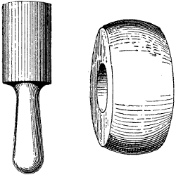
Fig. 1394.
Fig. 1394 represents standard plug and collar gauges. These tools are made to represent exact standard measurements, and obviously do no more than to disclose whether the piece measured is exactly to size or not. If the work is not to size they will not determine how much the error or difference is, hence they are gauges rather than measuring tools. It is obvious, however, that if the work is sufficiently near to size, the plug or male gauge may be forced in, or the collar or female gauge may be forced on, and in this case the tightness of the fit would indicate that the work was very near to standard size. But the use of such gauges in this way would rapidly wear them out, causing the plug gauge and also the collar to get smaller than its designated size, hence such gauges are intended to fit the work without friction, and at the same time without any play or looseness whatever. Probably the most accurate degree of fit would be indicated when the plug gauge would fit into the collar sufficiently to just hold its own weight when brought to rest while within the collar, and then slowly fall through if put in motion within the collar. It is obvious that both the plug and the collar cannot theoretically be of the same size or one would not pass within the other, but the difference that is sufficient to enable this to be done is so minute that it is practically too small to measure and of no importance.
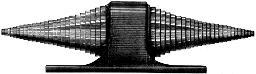
Fig. 1395.
When these gauges are used by the workmen, to fit the work to their wear is sufficient to render it necessary to have some other standard gauge to which they can be from time to time referred to test their accuracy, and for this purpose a standard such as in Fig. 1395 may be employed. It consists of a number of steel disks mounted on an arbor and carefully ground after hardening each to its standard size.
But a set of plug and collar gauges provide within themselves to a certain extent the means of testing them. Thus we may take a collar or female gauge of a certain size and place therein two or three plug gauges whose added diameters equal that of the female or collar gauge.
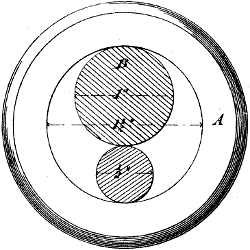
Fig. 1396.
In Fig. 1396, for example, the size of the female gauge a being 11⁄2 inches, that of the male b may be one inch, and that of c 1⁄2 an inch, and the two together should just fit the female. On the other hand, were we to use instead of b and c two males, 7⁄8 and 5⁄8 inches respectively, they should fit the female; or a 1⁄2 inch, a 5⁄8 inch and a 3⁄8 inch male gauge together should fit the female. By a series of tests of this description, the accuracy of the whole set may be tested; and by judicious combinations, a defect in the size of any gauge in the set may be detected.
Fig. 1397.
The wear of these gauges is the most at their ends, and the fit may be tested by placing the plug within the collar, as in Fig. 1397, and testing the same with the plug inserted various distances within the collar, exerting a slight pressure first in the direction of a and then of b, the amount of motion thus induced in the plug denoting the closeness of the fit.
In trying the fit of the plug by passing it well into or through the collar, the axis of the plug should be held true with that of the collar, and the plug while being pressed forward should be slightly rotated, which will cause the plug to enter more true and therefore more easily. The plug should be kept in motion and not allowed to come to rest while in the collar, because in that case the globules of the oil with which the surfaces are lubricated maintain a circular form and induce rolling friction so long as the plug is kept in motion, but flatten out, leaving sliding friction, so soon as the plug is at rest, the result being that the plug will become too tight in the collar to permit of its being removed by hand.
The surfaces of both the plug and the collar should be very carefully cleaned and oiled before being tried together, it being found that a film of oil will be interposed between the surfaces, notwithstanding the utmost accuracy of fit of the two, and this film of oil prevents undue abrasion or wear of the surfaces.
When great refinement of gauge diameter is necessary, it is obvious that all the gauges in a set should be adjusted to diameter while under an equal temperature, because a plug measuring an inch in diameter when at a temperature of, say, 60° will be of more than an inch diameter when under a temperature of, say, 90°.
It follows also that to carry this refinement still farther, the work to be measured if of the same material as the standard gauge should be of the same temperature as the gauge, when it will fit the gauge if applied under varying temperatures; but if a piece of work composed, say, of copper, be made to true gauge diameter when both it and the gauge are at a temperature of, say, 60°, it will not be to gauge diameter, and will not fit the gauge, if both be raised to 90° of temperature, because copper expands more than steel.
To carry the refinement to its extreme limit then, the gauge should be of the same metal as the work it is applied to whenever the two fitting parts of the work are of the same material. But suppose a steel pin is to be fitted as accurately as possible to a brass bush, how is it to be done to secure as accurate a fit as possible under varying temperatures? The two must be fitted at some equal temperature; if this be the lowest they will be subject to, the fit will vary by getting looser, if the highest, by getting tighter; in either case all the variation will be in one direction. If the medium temperature be selected, the fit will get tighter or looser as the temperature falls or rises. Now in workshop practice, where fit is the object sought and not a theoretical standard of size, the range of variation due to temperature and, generally, that due to a difference between the metals, is too minute to be of practical importance. To the latter, however, attention must, in the case of work of large diameter, be paid: thus, a brass piston a free fit at a temperature of 100° to a 12-inch cast-iron cylinder, will seize fast when both are at a temperature of, say, 250°. In such cases an allowance is made in conformity with the co-efficients of expansion.
In the case of the gauges, all that is practicable for ordinary work-shop variation of temperature is to make them of one kind and quality of material—as hard as possible and of standard diameter, when at about the mean temperature at which they will be when in use. In this case the limit of error, so far as variation from temperature is concerned, will be simply that due to the varying co-efficients of expansion of the metals of which the work is composed.

Fig. 1398.
To provide a standard of lineal measurement which shall not vary under changes of temperature it has been proposed to construct a gauge such as shown in Fig. 1398, in which a and b are bars of different metals whose lengths are in the inverse ratio of their co-efficients of expansion. It is evident that the difference of their lengths will be a constant quantity, and that if the two bars be fastened together at one end, the distance from the free end of b to the free end of a will not vary with ordinary differences in temperature.
Plug and collar gauges may be used for taper as well as for parallel fits, the taper fit possessing the advantage that the bolt or pin may be let farther into its hole to take up the wear. In a report to the Master Mechanics Association upon the subject of the propriety of recommending a standard taper for bolts for locomotive work, Mr. Coleman Sellers says:—
“As the commission given to me calls for a decision as to the taper of bolts used in locomotive work, it presupposes that taper bolts are a necessity. In our own practice we divide bolts into several classes, and our rule is that in every case where a through bolt can be used it must be used. If we cannot use a through bolt we use a stud, and where a stud cannot be used we put in a tap bolt, and the reason why a tap bolt comes last is because it is part and parcel of the machine itself. There are also black bolts and body bound bolts, the former being put into holes 1⁄16 inch larger than the bolt. It is possible in fastening a machine or locomotive together to use black bolts and body bound bolts. With body bound bolts it is customary for machine builders to use a straight reamer to true the hole, then turn the bolt and fit it into its place. It is held by many locomotive builders that the use of straight bolts is objectionable, on the score that if they are driven in tight there is much difficulty in getting them out, and where they are got out two or three times they become loose, and there is no means of making them tighter.
“There is no difficulty in making two bolts of commercially the same size. But there is a vast difference between absolute accuracy and commercial accuracy. Absolute accuracy is a thing that is not obtainable. What we have to strive for, then, is commercial accuracy. What system can we adopt that will enable workmen of limited capacity to do work that will be practically accurate? The taper bolt for certain purposes presents a very decided advantage. Bolts may be made practically of the same diameter, but holes cannot be made practically of the same diameter. Each one is only an approximation to correctness. We have here an ordinary fluted reamer (showing an excellent specimen of Betts Machine Company’s make). That reamer is intended to produce a straight hole, but having once passed through a hole the reamer will be slightly worn. The next time you pass it through it is a little duller, and every time you pass it through the hole must become smaller. There have been many attempts made to produce a reamer that should be adjustable. That, thanks to the gentlemen who are making such tools a speciality, has added a very useful tool to the machine shop—a reamer where the cutters are put in tapered and can be set up and the reamer enlarged and made to suit the gauge. This will enable us to make and maintain a commercially uniform hole in our work. But the successful use of a reamer of this kind depends upon the drill that precedes this reamer being made as nearly right as possible, so that the reamer will have little work to do. The less you give a reamer to do the longer it will maintain its size.