Volume 2 — Chapter XXXIII.—FORGING. (continued 2)
Reading edition
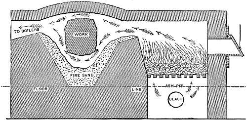
Fig. 3004.
These blooms are then taken to the large steam hammer and furnace by which the shaft is to be built up. The porter-bar, although merely a tool whereby to handle the mass, forms practically a base wherefrom to build up the shaft. The construction of the furnace is shown in Fig. 3004, the heat, after passing the work being used for the steam boiler that supplies steam to the steam hammer.
The porter-bar is held by a crane, the chain being placed in such position in the length of the porter-bar as to balance it. On the end of the porter-bar is a clamp, having arms by which the bar may be turned in the furnace and when under the hammer.
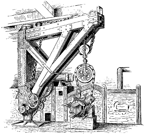
Fig. 3005.
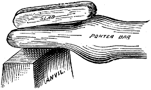
Fig. 3006.
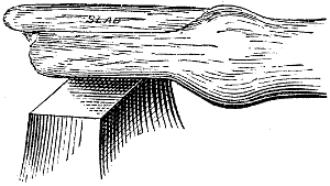
Fig. 3007.
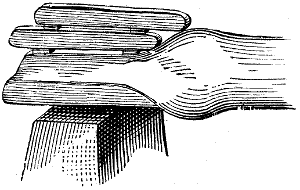
Fig. 3008.
Fig. 3005 represents the bar in position in the furnace, the aperture through which it was admitted having been closed up by bricks luted with clay, one brick only being left loose, so that it may be removed to examine the heat of the bar. The end of the bar is flattened somewhat, and a slab is laid upon it as in Fig. 3006, the appearance after the first weld being shown in Fig. 3007. It is then turned upside down, and blooms are piled upon it as in Fig. 3008. After these are welded the end is shaped up round and to size. The extreme end is again flattened, or “broken down,” as it is termed, and first a slab, and after reheating, blooms are added, as already explained; when these are welded and forged enough to consolidate the mass the mass is rounded up again, thus increasing the length of finished shaft. The end is again broken down and a slab added, and so on, the shaft thus being forged continuously from one end, and being composed of alternating slabs and blooms.
To forge this shaft 118,000 lbs. of blooms, 185 tons of coal, and 360 days of labor were required, the time occupied being 34 working days.
The slabs are simply forged pieces of larger dimensions than the blooms, and more thoroughly worked, the difference between slabs and blooms being that there is more waste with the blooms than with slabs, because the blooms heat quicker than the forged part of the crank.
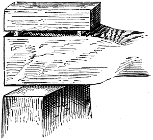
Fig. 3009.
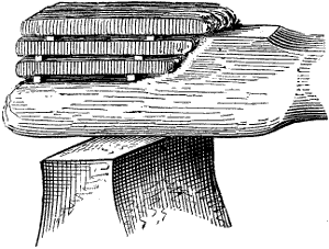
Fig. 3010.
Between both the slabs and the blooms there are placed rectangular pieces to hold them apart, and let the furnace heat pass between them, the arrangement of these pieces being shown in Figs. 3009 and 3010.
Figs. 3011 to 3024 (which are taken from Mechanics), represent the method employed to forge the crank shaft of the United States steamship Alert.
VOL. II. FORGING UNDER THE HAMMER. PLATE XVII.
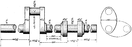
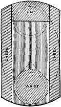
Fig. 3011. Fig. 3012.
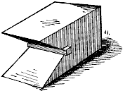
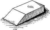
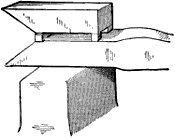
Fig. 3013. Fig. 3014. Fig. 3015.
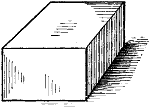
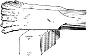
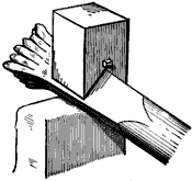
Fig. 3016. Fig. 3017. Fig. 3018.
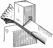
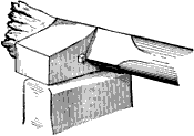
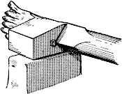
Fig. 3020. Fig. 3019. Fig. 3021.
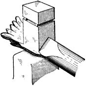
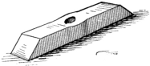
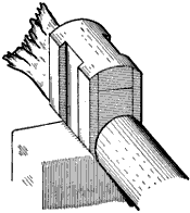
Fig. 3022. Fig. 3023. Fig. 3024.
Fig. 3011 represents the crank shaft, and Fig. 3012 an end sectional view, showing how the throws were built up. The first operation was to forge the saddles shown in Fig. 3013, these being the pieces that are shown between the cap and the wrist.
These saddles were made in halves, each half appearing as in Fig. 3014. From a pile and weld of blooms on the porter-bar, enough to make the two halves, one half was cut off. The other half was then drawn down on the porter-bar, and the first half was then piled on the latter, as shown in Fig. 3015. The square cross bar goes clear across and projects about an inch at each side. The back pieces were short bits. The square cross bar makes the saddle less liable to split in welding it on to the square shaft. Two “caps” were also made before the forging of the shaft itself began. These are shown in Fig. 3016, and their position in the finished work is shown in Fig. 3012.
The shaft itself was piled, welded, and drawn on the porter-bar in the usual manner, until the location of a crank was reached. Then a part of the work some distance from the new end was squared, as shown in Fig. 3017, and on this square the saddle was piled to heat and weld, as shown in Fig. 3018. As will be seen, the saddle rested upon the outer lines of the angle. The first blow was struck square on the top of the saddle, and after three or four blows the job presented the appearance shown in Fig. 3019. The piece was now turned so as to lie as shown in Fig. 3020, and worked with blows on the sides to the shape shown in Fig. 3021. This opened the top of the juncture of the saddle and squared the shaft down to the point where the weld was good. The piece was then turned back to the position shown in Fig. 3019, and worked with blows which again closed the angle on top, and made the weld good all through. The piece was then returned to the furnace, and at the next heat the saddle was squared up and finished, and the cap was piled on top of the saddle, as shown in Fig. 3022. The cap was welded on at the next heat, and two cheeks, like that shown in Fig. 3023, were laid upon one flat of the crank and pinned with 15⁄8-inch round pins. One of these pins is shown in the figure. Bits of iron were put under these cheek pieces in the usual manner. As the cheeks were very much smaller in section than the crank body, it was necessary to turn them over away from the fire, or else the cheeks would be burned before the crank body was hot enough to weld. To prevent the cheeks from falling off in the furnace the pins were put in as described before heating. After two cheek pieces had been welded on one side, two more were added on the opposite side, and then the crank was finished, as shown in Fig. 3024.
As will be seen by inspection of Fig. 3012, the weld between the cap and the saddle comes about the middle of the wrist, and the cheek pieces support the cap sideways. By means of the piles and welds described, the grain of the iron was so disposed as to offer the most resistance to working strains. This method was devised by Mr. Farrell Dorrity, of the Morgan Iron Works.
Forging Large Crank Shafts.[45]—The following paper describes the method of forging marine crank shafts adopted at the Lancefield Forge, Glasgow. It will be better understood if a short account is first given of the ordinary methods in use for the same purpose.
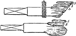
Fig. 3025.
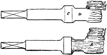
Fig. 3026.
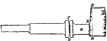
Fig. 3027.
“First Method.—The most common method is technically termed by the forgeman, ‘finishing the piece before him.’ He begins with a staff or stave, as shown in Fig. 3025, suspended by a chain from the crane, and made round for the convenience of manipulating under the steam hammer; this stave is used over and over again for many forgings, as it is merely the “porter” to carry the piece and enable it to be worked. The forging is begun by two or three slabs being placed on the stave as at s s s, and then inserted in the furnace. These slabs are flat blocks made up of pieces of scrap iron, which have been piled and heated, and then welded together. After being brought to a welding heat in the furnace, the slabs are withdrawn, placed under the steam hammer, and beaten down solid. The piece is then turned upside down, and two or three similar slabs placed on the opposite side, as shown at s s. When sufficient iron has been thus added to form the collar of the shaft (assuming it is to have a collar), it is rounded under the hammer, as at c, Fig. 3026, and the body of the shaft next to the collar is roughly formed, as at d. More slabs, s s s, are added to bring out the body, and afterwards the crank itself is proceeded with, on the same plan. The piece will begin to assume the appearance of a, Fig. 3026. Then more slabs are welded on the top, as at s s s, till the depth of the crank is obtained, after which the forgeman proceeds to finish the collar and body of the shaft, as shown. The collar on being finished is cut all round, as shown at c d, Fig. 3027, so that it may be more easily detached from the stave when the shaft is completed, leaving only sufficient connection to carry it till then. The forgeman then cuts the gable of the crank as at e g, and rounds up the body and neck as at b n, Fig. 3027.
“This, it will be observed, is a speedy process, and would invariably be adopted if it were not attended with a very serious drawback; it is very hazardous to the solidity of the forging. For it will be easily understood that not above a third of the crank itself can be thus formed, because the iron at the neck n would not carry a greater mass; if the whole mass of the crank, or even the half of it, was formed before the body and neck of the shaft were finished, a proper heat could not be taken on the body and neck for finishing, without the neck giving way or rupturing. Indeed, as it is, the undue proportion often causes the shaft to be strained at this part, where most strength should be, so that it is rendered weak, and a flaw is developed which by-and-by causes it to be removed from the steamer as dangerous and useless, if indeed it does not break outright; so that the forgeman, if he adopts this method, must be very careful to proportion the amount of iron he has massed in the furnace to the size of the body he is finishing, otherwise the weakening above mentioned will take place. All marine engineers will easily recognise this defect, which frequently occurs, but the cause of which is probably not well understood. Such a flaw will present a similar appearance to that shown at f, Fig. 3033, taken from an actual example.
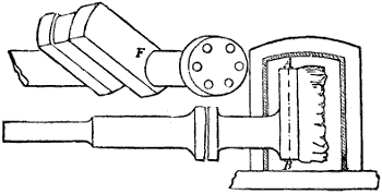
Fig. 3028.
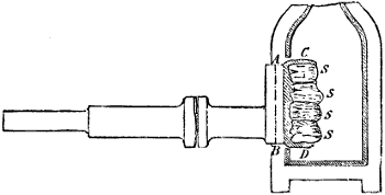
Fig. 3029.
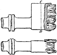
Fig. 3030.
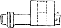
Fig. 3031.
“This difficulty of proportioning the part of the crank first forged to the size of the neck, will be still better understood by the appearance of it in the furnace, as shown in Fig. 3028. Having reached this stage, with one end of the shaft completed, as also that portion of the crank itself which of necessity was completed before the collar was cut, in order that the neck might be finished, no more iron can be added on the top edge, as it is up to the full depth already; it must therefore be added on the flat, as in Fig. 3029, where the piece is shown on its flat side in the furnace, the finished portion being outside the furnace door. A number of slabs s s s are then placed side by side to bring out the width of the crank further; these being welded down, the piece is turned upside down, and the process repeated on the other side. Afterwards other slabs are similarly placed on both sides, as shown in Fig. 3030, of which one is the flat, and the other is the edge view of the crank at this stage; and this is continued until sufficient iron has been massed to allow of the other gable of the crank being cut down, as at a, Fig. 3031, and sufficient also to allow of the other part of the body b being rounded and prepared for further piecing out.
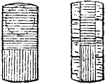
Fig. 3032.
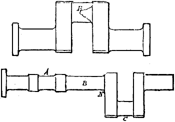
Fig. 3033.
“Now it will be observed that the first gable finished has the slabs all welded on the edge of the crank, and the hammering has all been on the edge; hence the subsequent hammering on the flat has a tendency to open up the weldings, if they have not been thoroughly made. A section taken at a b, Figs. 3028 and 3029, will show as in Fig. 3032, on the left, the weldings being across the web of the crank; the circle indicates the section which the crank pin would present if cut through there. But when the slabs are placed on the flat afterwards, some of the joinings of the ends of the slabs, or “scarf ends,” are certain to fall within the crank pin, as seen in Figs. 3028 and 3029; therefore the section through c d, Fig. 3030, will show somewhat like Fig. 3032 on the right, and the crank pin necessarily includes some of these flaws. The flaw thus produced, called ‘a scarf end in the pin,’ is readily recognizable by all marine engineers; at f, Fig. 3033, is a sketch from an actual occurrence.
“When the second gable is cut, and the other end is rounded, there is only the other collar to be put on (if a double-collared shaft), and the forging is completed.
This method is so speedy, compared with any other, that it is often resorted to even at the risk of making a bad forging; and too many broken shafts testify to the fact. Besides, it may be observed that in making a double crank shaft, while the one crank may be made in this way, the other must; for, the first crank, a, Fig. 3033, being completed, and the body, b, between the two cranks, also completed, the second crank, c, must of necessity be pieced off this body, even at the risk of the neck n being strained. This may account for the many instances in which one of the cranks of a double crank shaft gives way, rendering the shaft useless; and also for the plan, now almost universal, of making the two cranks separately and coupling them together; a further object being, no doubt, to have the means of replacing a defective half, if need be, without losing the whole shaft.
“At Lancefield, when a double crank shaft is to be made, the after crank, a, is first made by the method afterwards described, so as to insure that this crank, through which, as being next the propeller, all the power of the engine passes, is perfectly sound; and in piecing the other crank off the body, it is worked with slabs on the flat instead of on the edge, as afterwards described.
“The writer’s own opinion is that the crank is the most important part of the shaft, and, therefore, at all costs, should be made first. Others, no doubt, may take the same view, and, to avoid the risks just mentioned, may adopt the process described in the second method.
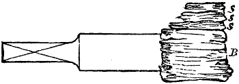
Fig. 3034.
“Second Method.—This method builds the middle first, and is called “turning the shaft end for end.” The shaft is begun from a stave, by the addition of slabs, as shown in Figs. 3034 and 3035; Fig. 3034 shows it with iron added in slabs, till a butt is formed, as at b, to form the nucleus of the crank; slabs s s s are then piled on it to bring the crank up to the height.
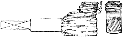
Fig. 3035.
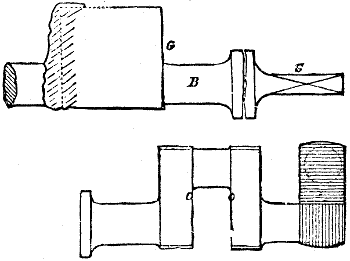
Fig. 3036.
“These are beaten down and welded, and more are added, as at s s s, Fig. 3035, till the full height of the crank is reached. Should the web (or edgeway of the crank) be thick, two slabs are frequently used to make up the breadth, placed edge to edge, as shown in Fig. 3035 on the right hand of the figure; the widths of these slabs are limited by that at which the shinglers can conveniently work and turn them under the steam hammer. The crank, however, is completed without any “side slabs,” for the beating down of the slabs on the edge will broaden out the mass, and give sufficient material to forge out the crank to the proper height by hammering on the flat. The crank is afterwards cut at the off gable at g, Fig. 3036, the body b pieced out and rounded, the collar welded on, and then a small stave s is drawn upon the end, to enable the forgeman to handle the piece when he “turns it end for end” to complete the other end of the shaft.
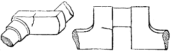
Fig. 3037.
“This method, though better than the last, is also objectionable; for though there is not equal risk of ’scarf ends’ in the pin, yet the weldings are all on the edge, as in the lower view, in Fig. 3036, where the section of the crank pin is shown by the dotted circle; and the cheeks of the crank, o o, are thus liable to give way if a heavy strain comes on the crank when at work. The defects arising from this cause are shown in Fig. 3037, and will be readily recognised by all engineers.
“Third Method.—Considerations such as these have led to the adoption of the third or Lancefield method.
Figs. 3038 and 3039.
Figs. 3040 and 3041.
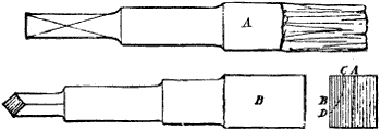
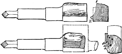
“Fig. 3038 shows the piece begun from the stave in the usual way, with the slabs all welded, however, on the flat, till a basis is formed for the building up of the crank. A portion a is roughly rounded to form the one end of the shaft, and the butt of the crank will present the appearance of a slightly elongated square, as shown at b, Fig. 3039. The workman then “scarfs” or hollows it down at one edge all along the side, as indicated in the end view by the dotted line from c to d; it will then present the appearance shown by the end view, Fig. 3040, being somewhat bulged outward at the points e and f. Three long thin slabs, Fig. 3042, shaped for the purpose, are then placed on the hollowed part, the piece lying flat in the furnace. These slabs are tapered a little the broad way, not on the length, and little pieces of iron are interposed between them, to keep the surfaces apart, and allow the flame free access between them. The object of making them thin is that they may be all equally heated, which is not so readily achieved when the slabs are thick; and the object of the tapering is to allow the slag to flow out freely when the uppermost slab is struck by the steam hammer. The surfaces thus get solidly welded.
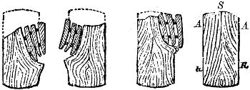
Fig. 3042.
“Fig. 3041 represents the slabs thus placed in elevation, and the figure on the right, in section. The slabs are forged long enough to go right across the whole width of the crank, excepting about 6 inches; this margin is necessary to allow of the lengthening out of the slabs to the whole width under the process of forging. After these slabs are perfectly welded, the piece is turned upside down, and the process is repeated on the other side, as shown in Fig. 3042. When welded down the mass has increased in depth as well. Another scarfing takes place on the first side, and then another on the second side, as shown in the figure, and so on, till the full size is obtained; and it will be seen, as in the right-hand view in Fig. 3042, that by this process of “scarfing” equally from, both sides, the iron from the very middle of the body of the shaft is drawn up quite to the crank pin. The location of the pin is indicated by a a, and it will be seen that by no possibility can there be a “scarf end” in the crank pin, as the slabs in all cases go right across the crank, and also that the cheeks of the cranks have no edge weldings crossing them, as in the previous cases; for the tail of a slab may be at r, Fig. 3042, while the other end may be at s. The fibre is also developed by the continuous drawing up of the iron consequent upon the repeated flat scarfings across the whole width of the crank. When the crank has been thus massed sufficiently large, it is cut at the gable, with sufficient material left to piece out the other body of the shaft. This is now done, the coupling welded on, and a small stave drawn on the end to enable the forgeman to manipulate it, when it is turned end for end, to complete the other end.
“These proceedings occupy longer time than either of the other two methods, and consequently costs a little more; but the advantage is well worth all the difference, as greater confidence can be entertained that the forging is every way satisfactory. In brief, by making the crank first, is avoided the liability to weakness at the neck, characteristic of the forgeman’s making the shaft before him, as in the first method; by the repeated ‘side scarfing’ is avoided the liability to fracture across the cheeks, consequent upon the edge weldings of both first and second methods; while by having the slabs the whole length of the width of the crank, any ‘scarf end’ in the length way of the crank pin is impossible (such as may occur in the first method); and the welding of the mass of the crank being wholly on the flat must tend to form a more solid forging than if hammered otherwise. Thus, if the forging is well heated and properly hammered, the system promises to insure that no weak part will be found in the shaft after it is finished and put to work. The writer believes, from the success which has already followed in every case the adoption of this method, that it will eventually be found that almost more depends on the mode in which a crank shaft forging is constructed than on the material of which it is made.
“This leads him to some observations regarding the material for such shafts. It is of course well known that in the early days of engineering, before the time when steam navigation had received a great impetus by the invention of the screw propeller, the connecting rods, cranks, shafts, &c., of land engines were all formed of cast iron; except, indeed, where the connecting rods were made of wood, strapped with plates of wrought iron, as frequently was the case with pumping, winding and blowing engines. In fact, all the parts that could be made of cast iron were so made, and the piston rods, bolts, keys, straps, and other smaller parts were alone made of malleable iron, the smaller pieces being made from rolled bars direct, as at present, and the larger made of similar bars, but placed side by side and bound together or ‘fagoted,’ as they were called, from their resemblance to a bundle of fagots. These bars, thus fagoted, were either brought to a welding heat in a smith’s hearth and welded under the sledge-hammers of the men called ‘strikers,’ or hammermen; or else heated in a furnace, and welded under the tilt hammer worked by a steam engine. By-and-by it was found necessary to adopt the stronger material, wrought iron, for parts hitherto confined to cast iron, because the latter was found too deficient in cohesion to stand the strains due to the power of high-pressure steam, which was now almost universally superseding the use of low-pressure steam in the condensing engine. The system of fagoting, however, was still carried out, even far into the history of marine engineering; but when the rapid increase in the dimensions of engines, both stationary and marine, called forth the steam hammer, and so rendered the forging of heavy masses comparatively easy, the system of fagoting fell into disuse, for the following reason: In making up a fagot, say, of 18 inches or 20 inches square, it was found, that in the furnace the outside bars would reach a welding heat much sooner than those in the middle; consequently on welding this fagot under the steam hammer, though the blow might reach to the centre, yet the interior would not be welded, while the surface was; hence the shaft or other forging would not be welded throughout, and it was no uncommon thing for a shaft to break and expose the internal bars quite loose and separate from each other.
“When it was seen that malleable was so much superior to cast iron, and that the system of fagoting was so imperfect, the adoption of ‘scrap iron,’ which was then composed principally of parings of boiler plates, pieces of cuttings from smiths’ shops, old bolts, horseshoes, angle iron, &c., became general. These being piled together in suitable pieces, and in a pile of suitable size, for the convenience of working, were brought to a welding heat, and beaten out into a slab, or oblong-shaped piece, ready for the forgeman; who would build two or three together, adding more when required, and so bring out his piece to a sufficient size to enable him to shape his forging out of it. Then it was that engineers, seeing what an increase of strength they obtained by these means, invariably specified on their drawings (as many of them still do), ‘These forgings are to be made of carefully selected scrap iron, free from flaws and defects.’
“To meet the requirements of their customers, therefore, forge-masters had now nothing to do but to select and use the best available scrap iron; but the universal adoption of iron hulls in place of wooden ones, conjoined with the rapid and unprecedented increase in steam navigation, soon introduced a class of scrap iron which did not possess the qualifications of good scrap, and also called for a very much greater supply of forgings than could be obtained in superior scrap iron. The consequence was that shafts of scrap iron, when turned and finished, became liable to exhibit streaks and seams, not due alone to imperfect welding in the forging, but likewise to the laminations and imperfections of the original scrap iron, which the process of piling and shingling into the slab was not sufficient to obliterate. So constantly does this yet occur that it causes a strong temptation to make such forgings of new iron puddled direct from the pig and then shingled into slabs or blooms, under the idea that these streaks and seams will thus be avoided, and that the iron will be improved almost to the condition of scrap iron, while being forged under the steam hammer. This, however, is found not to be the case. The forging is certainly free from the streaks of the scrap iron, but this is obtained at the expense of strength; for the material is too raw; it wants cohesion, and has not had the proper kind or amount of working to bring it to the condition of superior wrought iron. This method is still further tempting, inasmuch as it is far cheaper than the other; the material costs less than scrap iron, and, as it welds at a lower temperature, a forging can be much more quickly and easily made. Still, for whatever class of machinery it may be fitted, it should certainly be renewed in every case for a crank shaft or propeller shaft.
“From these considerations it has been the custom at Lancefield, in the preparation of the iron for crank shafts, to improve upon the ordinary condition of the scrap iron in the following manner: The pile is made up of carefully cleaned and selected scrap; it is brought to a welding heat, and then hammered under the steam hammer. But instead of being beaten into a flat slab for the forgeman, it is beaten into a square billet, which is afterwards rolled in the rolling-mill into a flat bar, as if for ‘best best’ merchant iron. By this additional heating, hammering and rolling, all the different qualities of the scrap iron composing the pile are merged into one homogeneous material, having the fibre given to it that was lost in the separated portions of the scrap iron; and this, when cut up into proper lengths, and again piled and shingled into the slab, results in a material possessing somewhat the closeness and density of steel, while retaining all the toughness and tenacity of superior malleable iron. The improved method of constructing the forging, previously detailed, is worthy the use of this superior material; and both having been adopted at Lancefield with results which have commended themselves so unmistakably to many engineers, that they now not only specify the material, but stipulate for the mode of manufacture, it is thought the system has only to be more widely known in order to be universally adopted. It is certain to give greater confidence in the endurance of such important parts of the machinery, although this confidence may have to be obtained by a small increase in the cost, due to the extra workmanship both on the material and on the forging.
“When we take into consideration the vastly accelerated speed of the marine engine in late years, and the many disastrous effects which follow the breaking of a shaft at sea—also that the tendency of the age is still towards much higher pressures, and further lengthening of stroke it is not surprising that improvement in such an important part as the crank shaft should be eagerly sought after; but it has hitherto been sought in the direction of the material alone. Cast steel has been advocated, and brought to some extent into use; but its expense renders such shafts costly out of all proportion to the other parts of the engine; while, in the event of their heating when at work (a very frequent casualty), and having the water-hose directed upon the crank pin or journals, it cannot be expected that the material will behave any better, or even so well, as tough wrought iron. What is termed puddled steel is liable to the same objection, and probably, from its mode of manufacture, in a still greater degree. The so-called mild steel is no doubt proving itself a superior material, and yielding good results when rolled into ship or boiler plates. But thus prepared it is more costly than ‘rolled scrap bar;’ and if not rolled, but cast into an ingot, then it possesses some of the crystalline characteristics of steel, with all the disadvantages attending its manipulation into a forging.
“For extra large crank shafts, the fear of unsoundness, arising from the ordinary mode of forging, has led some engineers to consider the propriety of building the shafts and cranks in separate pieces. This, with engineers generally, has not hitherto been looked upon with favor; as the fewer the pieces the more rigid the shaft. Moreover, the increased weight necessitated by this separate building is viewed as a disadvantage, even although it were not attended with greater cost, as undoubtedly it is.
“The material and mode of manufacture advocated in this paper may tend to dissipate some of these apprehensions. They will not obviate defective construction in the engines themselves, or faulty proportion of their parts, or neglectful supervision of their working, but they will reduce to a minimum the risk of breakage in such untoward circumstances. If any objection be taken on the score of extra size, the enterprise which a quarter of a century ago engaged in the making of the unusually large shafts necessary for the ‘Great Eastern’ may still be trusted to meet the advancing requirements of the present day.”
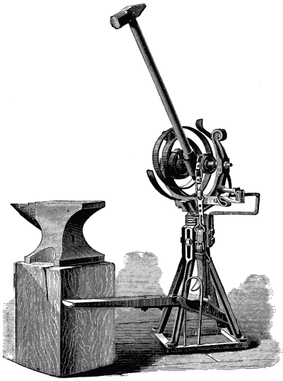
Fig. 3043.
Fig. 3043 represents a foot-power hammer or Oliver. The hammer is upon a shaft in bearings, and is held in the position shown by an open coiled spring. On the shaft is a chain pulley, the other end of the chain being connected through a leather strap to the treadle. Means are provided to adjust the height to which the hammer will lift to bring the hammer face fair with the work and to give the required degree of tension to the spring.
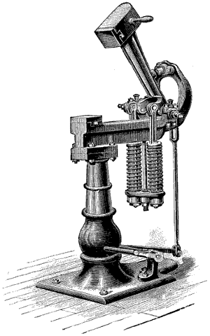
Fig. 3044.
Fig. 3044 represents a Standish’s foot-power hammer, in which the hammer and the anvil are provided with dovetail seats for receiving dies, swages, &c. The force of the blow is regulated by the height to which the hammer is raised, which may be adjusted by the nuts beneath the spiral springs. The handle on the hammer is for pulling the hammer down by hand when adjusting the lower die fair with the upper one.
What are known as power hammers are those driven by belt and pulley; while those known as trip hammers have their helve lifted through the medium of revolving lugs or cams. Steam hammers are those in which the hammer is lifted by a piston in a steam cylinder; while in hydraulic hammers, the hammer is moved by water pressure.
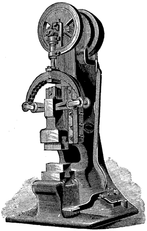
Fig. 3045.
Fig. 3045 represents a Justice’s power hammer, in which the hammer is guided in a slideway and is operated by leather straps attached to the ends of a spring, at the crown of which is attached a connecting rod driven by a crank disk. The stroke is altered by means of placing the crank pin in the required position in the slot in the crank disk. By means of gibs the hammer may be set to match the dies. The pulley is provided with a friction clutch operated by the treadle, shown.
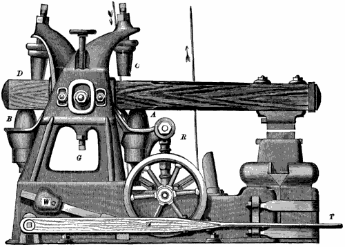
Fig. 3046.
Fig. 3046 represents a Bradley’s Cushioned Hammer, in which motion is obtained by a belt passing over a pulley on a crank shaft, whose connecting rod r is capable of adjustment for length, so as to govern the distance to which the hammer shall fall, which obviously varies with different sizes of work. The hammer is lifted through the medium of a rubber cushion a, seated in a casting to one end of which is connected the rod r, while the other end is pivoted. The lever to which the hammer is affixed is raised against the compression of the rubber cushion b, and at the top of its stroke also meets the rubber cushion c; hence these two cushions accelerate its motion after the crank has passed its highest point of revolution. The cushion d prevents the rebound of the hammer after the blow is struck; hence as a result of these cushions, heavy or light blows may be struck with great rapidity and regularity. The weight w is on a lever that actuates a break upon the wheel shown at the side, so as to enable the stopping of the hammer quickly. The machine is put in motion by pressing the foot upon the treadle t, which operates a belt tightener, the belt running loose when the treadle is released.
The hammer lever or helve is adjustable for height by means of the screw g and hand-wheel h, which raise or lower the bearings in which the helve journals are carried. This is necessary, because as the helve moves in the arc of a circle the faces of the upper and lower die, or of the hammer and the anvil, as the case may be, can only come fair at one particular point in the path of the hammer; hence in proportion as the blow terminates (by meeting the work surface) farther from the anvil face, the pivot or journal of the helve must be raised, so that the journal will be horizontally level (or as nearly so as possible) with the hammer face at the moment the blow is delivered.
By giving motion to the helve through the medium of cushions, a direct mechanical connection, and the destructive concussion that would accompany the same, is avoided; hence a high speed may be obtained without the frequent breakage that would otherwise ensue.
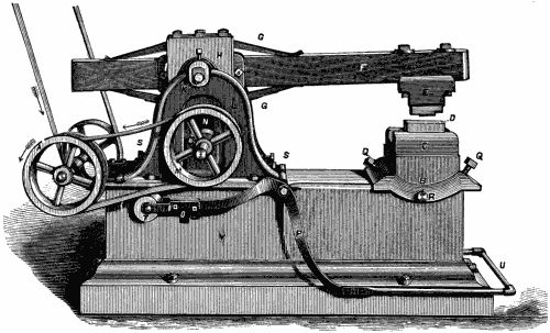
Fig. 3047.
Fig. 3047 represents Corr’s power hammer, the construction being as follows: The semi-elliptic springs, shown on top and bottom of the beam, serve to balance the stroke, so that the hammer may run from 350 to 450 strokes per minute, with safety to the machinery. The hammer is adapted to almost any form or kind of forging. Large dies may be inserted for various kinds of forming and welding, such as making plough-shares and other articles, which require that the operation be commenced with a light tap, and increased to a heavy blow at the will of the operator.
The whole structure is mounted on a substantial iron bed v, 18 inches deep, 22 inches wide and 51⁄2 feet long. Attached to this bed v are two circular arms l; between them is pivoted near their top, at k, an oscillating frame h, having a longitudinal opening, in which is attached two semi-elliptic springs g g, and two plates i, with trunnions projecting laterally through the oscillating frame at k; the hammer beam f is inserted between the springs g g, and the trunnion plates i, which are bolted firmly to beam f at i; the ends of the trunnions and outsides of the oscillating frame h rest evenly against the inside of the circular arms l; at k a shaft is passed through the trunnions and beam f, and made rigid in them with its ends resting in boxing at k. Caps are provided to cover the ends of the boxing and shaft with set-screws projecting against the ends of the shaft, which secures it against end play.
By these mechanical arrangements the beam f and oscillator h are securely attached independently, vibrating on one common centre, allowing no side play of the hammer e, admitting f to the free action of the springs g g; in the lower end of the oscillating frame at n is a lateral opening 10 inches vertically by 6 inches longitudinally and 4 inches laterally, with flanges projecting longitudinally one inch into this opening from both sides. This makes the opening two inches smaller on the outside than the internal cavity; the rear and front internal walls are provided with steel plates, 4 by 10 inches, 1⁄4 thick, resting against the inner ends of four set-screws, not shown, provided to adjust these plates to or from the sliding box at n, to compensate for wear and prevent lost motion. These plates and flanges form slides and guides between which a loose box and eccentric is provided with shaft projecting laterally through boxing at n, which project upwards from an adjustable frame immediately under the oscillator h; this permanently locates the eccentric and shaft in the lateral opening in the oscillator h, at n. The adjustable frame mentioned rests on suitable bearings on the inside of the circular arms l, and is fastened down by four bolts passing through suitable slots in the adjustable frame, entering the bearings on the arms l. This frame is adjusted back or forth by set-screws s s; this adjustment is for the purpose of giving a greater or less distance between the anvil and hammer at d, as may be desired for large or small work, long or short dies, &c.
The anvil b, weighing about 500 lbs., sits down in the bed at r and rests on circular bearings (between r and b), which radiate to the centre of the top of the anvil at d, and is held rigidly in any position longitudinally desired by set-screws q q, with their inner ends resting on shoulders on the sides of the anvil b, which projects down about ten inches; between this lower projection and the internal wall of the bed is sufficient space to admit of any adjustment desired. This lateral adjustment is accomplished by set-screws r, passing through the sides of the bed v, with their inner ends resting against the anvil which holds it rigid at any lateral adjustment. By this arrangement the anvil is accommodated to all and any class of work or shape of dies.
The anvil is constructed in two parts. Four inches of the top c may be taken off, leaving a suitable place to insert large dies for various purposes, such as dies for welding plough-shares and dies for forging journals on large shafts. A counter-shaft, provided with suitable pulleys, is attached on the rear end of the bed; this shaft is kept constantly in speed and power by the vertical belt in the direction indicated by the arrow; the other end of the shaft is provided with a flanged pulley, corresponding to a flanged pulley m, on the eccentric shaft; around these pulleys is placed a loose belt, as shown; in contact with this is a press pulley t, adjustably attached by two arms to the projecting end of the treadle p at o. If the foot be placed on the treadle at u and it be pressed down, the break on the opposite side breaks contact with the balance wheel (not shown); the press pulley will at the same time tighten the loose belt on the flanged pulleys. This gives motion to the pulley m, in the direction indicated by the arrow. Its motion is increased by a heavier pressure until it attains the same speed as the other flanged pulley; this would be the full speed, which may be diminished to any speed desired by lessening the pressure on the loose belt. By this means motion and power is given to the eccentric, which carries back and forth the lower end of the oscillating frame h; this gives vertical motion to the springs g g, and this imparts corresponding motion to the beam f. These springs accomplish a threefold object:
1st. They carry the hammer e up and down.
2nd. They cushion the hammer at the returning points and give off that power which was stored in them while cushioning.
3rd. By the power exerted in the machinery they follow up and impart still greater force to the blow.
It is found by this arrangement of eccentric loose box and oscillator that when the machinery is moved in the direction indicated by the arrow, that the downward stroke is one-sixth quicker than the up stroke; this is a natural result, for the down stroke is performed while the eccentric is revolving above the centre of its shaft and nearest the fulcrum of the operator h. With the present arrangement the downward stroke is performed with 5⁄12 of the revolution and the up stroke is performed with 7⁄12; the difference is 2⁄12, which equals one-sixth. The up stroke is performed while the eccentric is revolving below the centre of its shaft and in that part farthest from the fulcrum of the oscillator h, so if the machinery were reversed the quick stroke would be up and the slow stroke would be down.
Large image (164 kB).
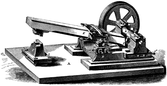
Fig. 3048.
In Fig. 3048 is shown a Kingsley’s trip hammer. The main bed or foundation plate a carries the bed plate or frame b, at one end of which are the pillar blocks c, which afford journal bearing to the casting carrying the hammer shaft e, being fastened thereto by the clamp d. These journals are the centre of motion of the hammer helve e.
At the other end of the bed plate b, are the pillar blocks f, affording journal bearing to the cam and fly-wheel shaft, a′′ is the tripping cam, which is provided with two toes or cam arms, which meet the tripping piece b′′, and this gives the hammer two strokes in a revolution of the fly-wheel shaft or cam shaft g. The stroke of the hammer may be altered by means of the set-screws c′′, which move the pillar blocks f, so that the cam toes a′′ have contact with the tripping piece b′′ through more or less of the revolution of a′′; the pillar blocks f being retained in their adjusted position by means of the set-screws shown below them in the bed piece b.
By the following means provision is made whereby the face of the hammer may be set out of parallel with that of the anvil block or lower die d′.
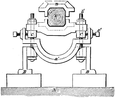
Fig. 3049.
Fig. 3049 is a sectional view through the pillar blocks c, and casting and clamp d. The pillar blocks c c are carried in a semicircular frame a′, hence by unscrewing the bolts b′ and screwing up the pillar block on the other side, the journals are thrown out of parallel, and the plane of motion of the hammershaft is altered so that the face of the upper die does not meet that of the anvil die fair to an amount which may be varied at will by operating the screws b′. The object of this is to enable the forging taper (as in sword blades) with common dies, and thus to save the making of special dies for each degree of taper required.
Similar provision is made in the anvil block which is easier to set, providing the degree of taper is within the limit of its range, of movement, otherwise the hammer also may be set.
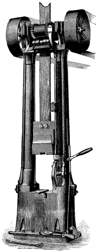
Fig. 3050.
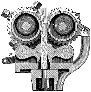
Fig. 3051.
Fig. 3050 represents a drop hammer, and Fig. 3051 is a sectional view of the lifting mechanism.
This machine consists of a base or anvil, a hammer which moves up and down between two uprights, and a lifting device, which is secured to the top of the uprights.
A board secured to the hammer passes up between two friction rolls, which revolve in opposite directions. When the two rolls are moved towards each other, the friction on the board causes the hammer to rise; and when again separated the hammer will fall. The back roll is keyed to a shaft, on each end of which is a driving-pulley; and thus by the use of two pulleys on the same shaft, equal wear comes on the bearings in which it revolves. The front roll turns freely on its shaft, and is driven by the back roll being geared to it. To secure to the gears both strength and durability, they are made with wide faces, are geared at both ends, and the teeth are of peculiar shape.
The bearings to the shaft, on which the front roll revolves freely, are eccentric to the roll, and a partial revolution of the shaft moves the front towards the back roll, pinching the board. To an arm which is secured to the front shaft is fastened the upright rod, the upward movement of which opens the rolls, and whose downward movement closes the same; the weight of the rod being sufficient to cause the hammer to rise. This arrangement, simple and yet substantial, dispenses with the two eccentric-armed bushings, and the spreading of the upright rod at the top to reach both bushings, which caused so much trouble in the old way. In place of the dog which is usually used to hold up the hammer, (which is limited in adjustment to holes located at fixed distances in one of the uprights, necessitating not only the removal of the dog to another hole, and connecting and disconnecting the same to the treadle, but also the most accurate adjustment of the collar on the upright rod to the dog holding the hammer), we use a pair of clamps, located on the lifter, under the rolls. These clamps, holding the hammer centrally, prevent the side blow against the upright, the inevitable result of the contact of hammer and dog, when the former is only held on one side, as it must be, by the use of the dog. The opening of the clamps by the foot-treadle allows the hammer to fall; and the clamps are so made that the hammer will ascend freely, whether the foot is on the treadle or not, and if the foot is off the treadle, will hold up the hammer at any point where it may be arrested in its upward movement. It will be readily seen that the only adjustment required is that of the collar on the upright rod, to any height of blow desired.
This machine has two treadles, one connected to the clamps, and the other to a lever which operates the upright rod.
To obtain repeated blows with one motion of the foot, place the foot upon the treadle connected to the clamps. If variable blows are wanted, place the foot upon the other treadle, and the hammer will follow the motion of the foot. This extra treadle is a late improvement, and is not shown in the cut. The operation required to obtain automatically any number of blows of the same height is described as follows:—
Pressure upon the treadle opens the clamps and allows the hammer to fall; just before the dies come together, the trip at the bottom which holds up the upright rod is released, and allows the rod to drop; this closes the rolls, causing the hammer to ascend. The hammer continues to rise until it strikes the collar on the upright rod, and, lifting the rod, opens the rolls, removing the pressure upon the board, and allows the trip at the bottom to go under to hold the rod up, and the hammer remains suspended, provided the foot is off the treadle. So long as pressure is kept on the treadle, the blows of the hammer will be continuous; but upon removal of the pressure, the hammer will assume its original position.
To procure variable blows, the operation is as follows:—
Pressure upon the treadle connected to the lever which operates the upright rod communicates itself to the treadle that opens the clamps, and the hammer falls; a locking device (not shown in cut) keeps this treadle down, and on completion of the variable blows wanted, removal of the foot from the treadle disconnects the locking device, and the hammer goes up to its original position, and is there held by the clamps.
When the work is such that the operator requires an assistant, variable blows may be obtained by the use of the hand lever by this assistant.
A gentle pressure upon the treadle will allow the hammer to go down slowly, but it will stop and remain suspended at any point as soon as the pressure is removed. The hammer can also be arrested at any point on its way up, by bringing into action the hand lever, so that the next blow can be given from a state of rest at a less height than the collar is set for. The clamps in holding up the hammer keep the board from touching either roll, and prevent the same from being worn uneven when not in use.
The back roll is made adjustable to different thicknesses of lifting board, as are also the clamps.
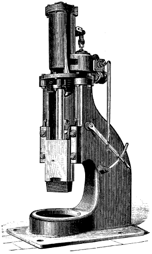
Fig. 3052.
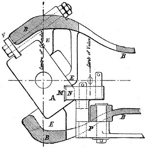
Fig. 3053.
Large image (145 kB).
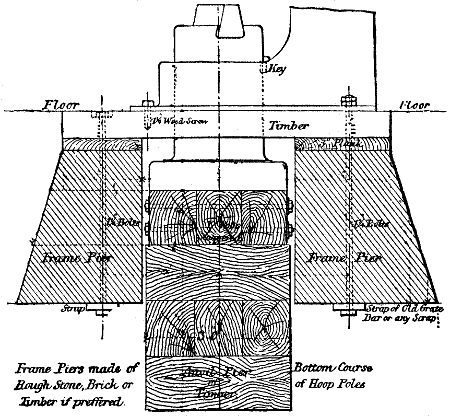
Fig. 3054.
Large
image
(128 kB).
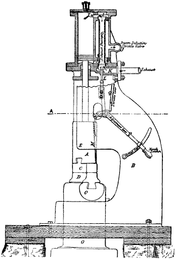
Fig. 3055.
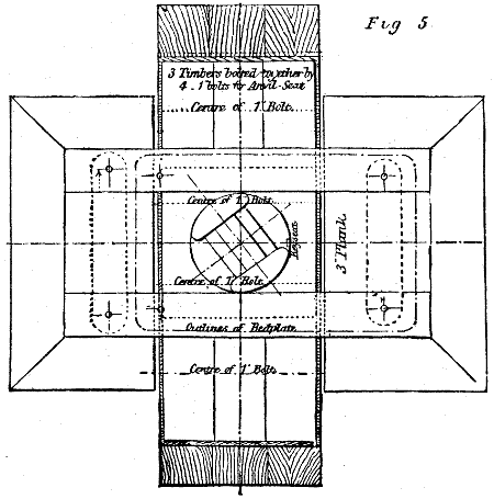
Fig. 3056.
Figures from 3052 to 3056 represent a steam hammer. The head a is set at an angle in the frame. The anvil or die c is oblong, as is also the anvil die d. The object of this arrangement is to enable the workman, after drawing out his work across the short way of the die, to turn it and finish it lengthwise without being inconvenienced by the frame. By this means skew and T-shaped dies can be dispensed with, and the full service of the ram utilised. The latter is moved between the guides e e, and held in place by the steel plate f, bolted through the frame b. The valve g is a plain cylinder of cast iron, enlarged at each end to work in the cylindrical seats h h, in which the ports i i are placed. Steam is admitted through the valve j, and circulates round the valve g, between the seats. The exhaust chamber k is below the cylinder, which therefore drains condensed steam into it at each stroke through the lower steam port. The exhaust above the piston passes down through the interior of the valve, as shown by the arrow on the drawing. The valve stem l is connected with the valves in the exhaust chamber. No stuffing box is therefore required, there being only atmospheric pressure on each side of it. This combination enables the valve to be so perfectly balanced that it will drop by its own weight while under steam.
The automatic motion is obtained by an inclined plane m upon the ram a, which actuates the rocker n, the outer arm of which is connected by a link to the valve stem, and thus gives motion to the valve. The valve is caused to rise in the up-stroke by means of the rocker n and its connections, through the inclined plane. The steam is thus admitted to the top, which drives down the piston, while the valve and its connections follow by gravity, thus reducing considerably the friction and wear upon the valves. In very quick work the fall of the valves may be accelerated by the aid of a spring; or it may be retarded in heavy work by friction springs, so as to obtain a heavier blow by a fuller admission of steam. For general work, however, the arrangement shown is perfectly effective, and as the rocker n is hung upon the adjustment lever p, any required variation can be obtained by the movement of the lever. Single blows can be struck with any degree of force, or a rapid succession of constant or variable strokes may be given.
The anvil o rests upon a separate foundation, in order to reduce the effect of concussion upon the frame. The drawing illustrates the arrangement. The bed is long, extending beyond the hammer on each side so as to give plenty of area, and the ends are left open for convenient access in case the anvil should settle and require re-adjustment.
Other forms of hammers having the same general principles of construction are as follows:—
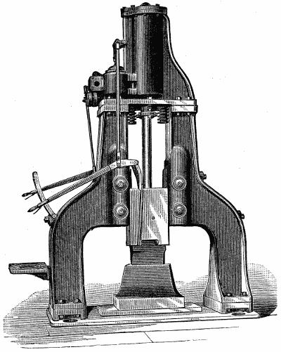
Fig. 3057.
Fig. 3057 represents a double frame hammer, the weight of the hammer being supplemented by steam pressure. The spiral springs shown beneath the cylinder are to prevent the hammer from striking the cylinder and causing breakage from careless handling by the operator. The valve gear is arranged for operation either automatically or by hand.
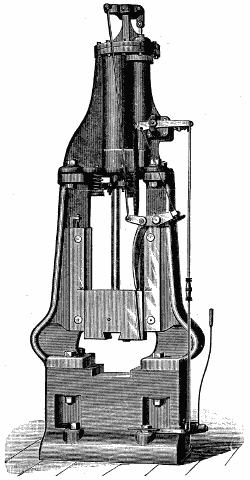
Fig. 3058.
Fig. 3058 represents a double frame steam drop hammer for stamping work out in formers or dies. The frames are bolted to the anvil base and the ram for the top die is guided by vertical slides on the inner face of the frame. Shoes are provided, whereby the wear of the ram and of the slides may be taken up, and the upper die kept properly matched with the lower one.
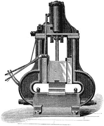
Fig. 3059.
Fig. 3059 represents a double frame steam drop hammer for locomotive and car axles and truck bars. The frame is spread at the base to admit wide work, and the upper surface of the base is provided with rollers supported by springs, these rollers supporting the work. The same may be operated automatically or by hand.
The hydraulic forging press at the Edgemore Iron Works of Wilmington, Delaware, consists of a piston operating in a cylinder, and having at its lower end a head guided by four cylindrical columns that secure the base plate, or anvil, as it may be termed, to the cylinder. To the above-mentioned head is secured the upper die, the lower one being secured to the base plate.
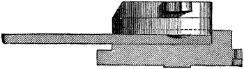
Fig. 3060.
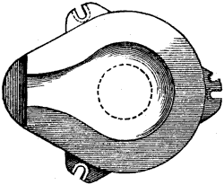
Fig. 3061.
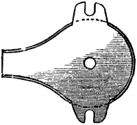
Fig. 3062.
Fig. 3060 represents a female die, and Fig. 3061 plan of another female die, and Fig. 3062 plan of male die used in connection with the press to forge the eye bars for the Brooklyn Bridge, five pieces each an inch thick being welded to the bar and pressed into shape at one operation.
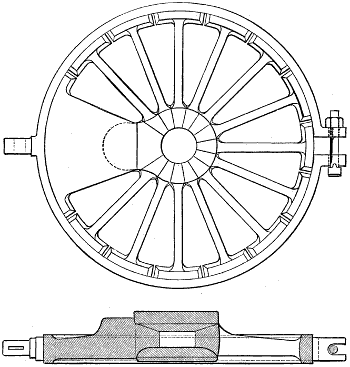
Fig. 3063.
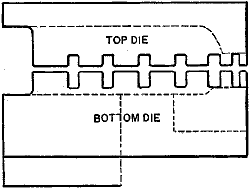
Fig. 3064.
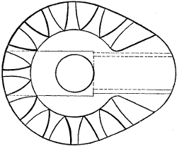
Fig. 3065.
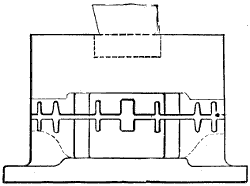
Fig. 3066.
Figures from 3063 to 3066 represent a locomotive driving wheel ready to have its hub welded by hydraulic pressure. The spokes having been forged are held together by a band or hoop, as shown. The thickness of the hub or boss is made up by the rings or washers shown in the sectional view. The dies under which the welding is done are shown in Figs. 3064 and 3066.
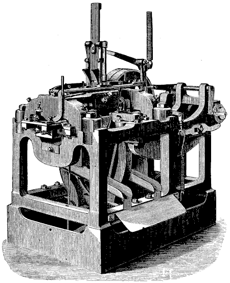
Fig. 3067.
Thin forgings are often made by compression between two rollers, the form of the surface of the rollers, or projections or depressions upon the same, pressing the forging to shape.
Thus, in Fig. 3068 are shown a pair of rolls a b, p representing a piece of work, and c d two cam pieces fast upon the roll surfaces; s is a fixed stop.
Suppose the work to be pushed through the rolls and to rest against the stop s, then when the cams c d meet it they will pull it through and reduce its thickness by compression towards the workman. The rollers are obviously rotated by gear wheels; but they are sometimes provided with a certain amount of give or elasticity at their bearings, so that the reduction of work diameter may be obtained by several passages of the work through the rolls.
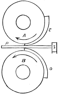
Fig. 3068.
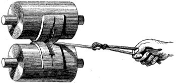
Fig. 3069.
The shape of the cams, as c d, determines that of the work; thus in Fig. 3069 is shown a pair of rolls for forming knife blades, each cam having sunk in it a die equal in depth to half the thickness of the knife.
If the work is very short in comparison with the circumference of the rolls, two, three, or more cams may be arranged around the circumference, making an equal number of forgings or impressions, as the case may be, at each revolution of the rolls.
In Fig. 3067 is shown a nail-forging machine for producing, from strip iron, nails similar to hand-made, at rates varying from two to three hundred per minute, and lengths of from six to one inch, two nails being completed at each revolution of the driving shaft of the machine. The framing consists chiefly of a main casting, to which are fixed an upper frame, carriages for the driving shaft, and other details. The principal moving part is a heavy steel slide, deriving its motion from a crank pin with adjustable throw; this slide carries two shears, two gripping dies, and sundry indispensable appendages, to some of which it imparts motions for guiding the nails between the stages of cutting off and finishing.
The successive operations by which each nail is perfected are as follows:—
A piece of iron about six inches long, and of a width and thickness respectively of the finished nail, is inserted at a red heat to the feeder of the machine; a narrow strip is immediately cut off the lower side of the heated iron, and by the motion of the steel slide is carried to and pressed against a fixed die; while in this position another die rises at right angles and presses the partially formed nail against another fixed die. Thus the headless nail is firmly held on its four sides, and while in this position a lever, moved by a cam, and carrying a suitable tool, advances and forms the head, thus completing the nail. The return motion of the steel slide releases the nail, leaving it free to fall, but as its weight is not sufficient to insure this happening, a “knocker off” is provided, which at the right moment forcibly ejects the nail by way of a guiding shoot into a receptacle placed outside the machine. It is to be noted that the tools for shearing and gripping, and which have to be changed with each different size of nail, are made of a special mixture of cast iron. They are thus easy of preparation and renewal, while at the same time answering their intended purpose as well as or better than the finest cast steel, at less than half the cost. The whole of the machine is carried upon an open-top cast-iron water tank, serving as a receptacle for the tongs and tools heated in withdrawing the iron from the furnace.
Large
image
(110 kB).
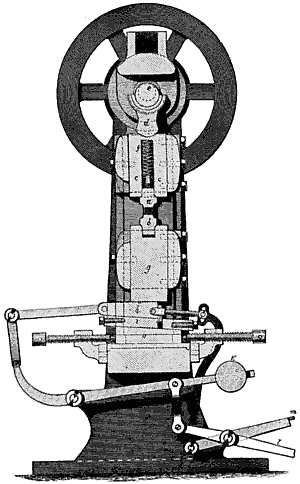
Fig. 3070.
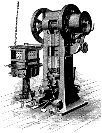
Fig. 3071.
Figs. 3070 and 3071 represent a machine for forging threads on rods and screws. As forgings, the threads are beautifully clean, and for the general work of coach screws much stronger than the cut threads. A perspective view of the machine is given in Fig. 3070, and a vertical of it shown in Fig. 3071. In the former figure, a b are the screw dies. The rod or bolt to be threaded is placed upon the lower die b, and fed forward while screwing it. The upper die is mounted on a slide c, which is actuated in the downward direction by an eccentric e on the main shaft and the toggle-bar d, the upward motion being obtained by an internal spiral spring f. The lower die b is carried in a slide g, and is adjusted at the proper distance from the upper die by means of wedge h, and the inclined plate i, beneath the slide g. The wedge h is operated by a pedal l, and secured in its highest position by a bolt j, received in a mortice made in the plate i, the bolt being operated by a pedal m. In order to release the wedge and return it to its lowest position, the bolt is raised by pressing down the pedal m, whereby the wedge is free to be returned by the counterweights k, in connection with pedal l; slide g, carrying the lower die, then descends by its own gravity, and so separates the two dies sufficiently to allow of the removal of the screw-bolt or rod therefrom. To compensate for the wear of the dies, and admit of their adjustment, another wedge o, with screw adjustment, is disposed below the inclined plate i.
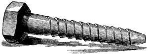
Fig. 3072.
Fig. 3072 represents a lag screw forged by the machine.
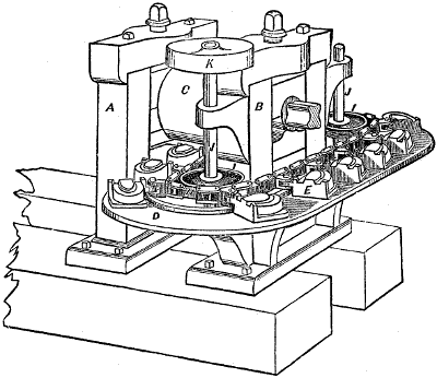
Fig. 3073.
Fig. 3073 represents a finishing machine for horseshoes. The bars of iron are rolled with the creases (for the nail heads of the finished shoe) in them. The blanks for the shoes are then cut to length and bent, and the nail holes punched. The shoes then pass to a machine, Fig. 3073, which consists of a frame a b, carrying the roll c, above the table d, and a second roll, not shown in the cut, but being directly beneath c, there being between these two rolls sufficient space to let the dies (which press the shoes into shape) pass.
These dies rest upon the table d, and are carried around upon it in a direction from left to right of the chain h, to the links of which the dies are attached. This chain is operated by the vertical shaft j, having a pulley for belt power at k.
As each die approaches the rollers, a shoe (cut to length, creased, and punched as already described) is placed on it, and on reaching the rolls the shoe is pressed into form on the die by the rolls, the bottom roll serving as a rolling bed so as to reduce the friction that would be due to a sliding motion on the bottom of the die. The top roll c, which presses the shoe into the die is driven by power.
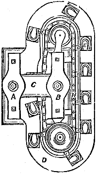
Fig. 3074.
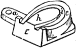
Fig. 3075.
A plan view of the machine is shown in Fig. 3074, and a view showing the shape of the dies is given in Fig. 3075.
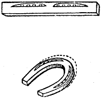
Fig. 3076.
The surface h forms the frog. To give the required concavity to the toe and sides of the shoe, the surface i is made convex, and tapered or inclined towards h. The tread e is deepest at the heel on both sides, and highest at the toe. It is obvious that by suitably shaping the surfaces h, i, and e, any required form may be given to the shoe. Fig. 3076 represents a shoe creased, punched, and bent ready to be passed to the machine.
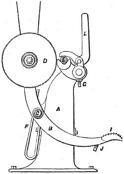
Fig. 3077.
Fig. 3077 represents a circular saw for cutting off hot iron; a is the frame of the machine, the arm b pivoted at c carrying the saw d; f is a spring bolted to the frame and serving to hold the saw in the position shown. The work e is gripped by the lever l, which is pushed over by hand. The lever l is adjusted to suit different sizes of work by the screw g, which raises or lowers the piece h, to which l is pivoted. The saw is brought into contact with the work, and fed to it by applying the foot to the lever or arm b at i, the screw j being made to contact with the foot of the machine by the time the saw has passed through the work, thus preventing the saw from moving too far forward after passing through the work.