Volume 1 — Chapter XI.—DRILLING AND BORING IN THE LATHE. (continued 2)
Reading edition
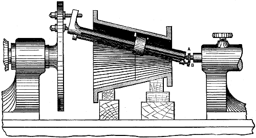
Fig. 1143.
Boring Tapers with a Boring Bar or Attachment.—In cases where the degree of taper is very great a live centre may be bolted to a chuck plate, as in Fig. 1143, by which means any degree of taper may be bored. Instead of a star feed, a gear feed may be provided by fastening one gear, as a, on the dead centre, and another, as b, on the feed-screw. The cutting tool must stand on the side of the sliding-head—that is, farthest from the line of lathe centres.
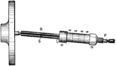
Fig. 1144.
Small holes may readily be bored taper with a bar set over as in Fig. 1144, the work being carried by a chuck. The head h carries the cutting tool, having a feather which projects into the spline s to prevent the head from rotating on the bar. To prevent the bar from rotating, it is squared on the end f to receive a wrench. The head is fed by the nut n, which is screwed upon the bar. w, w, w, w are merely washers used to bring the nut n at the end of the thread when the head is near the mouth of the work, their number, therefore, depending upon the depth of the work. A bar of this kind is more rigid than a tool held in the tool post.
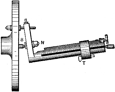
Fig. 1145.
Instead of setting the dead centre of the lathe over, the bar may be set over, as in Fig. 1145, in which the boring tool is carried in the sliding head at t, and is fed by a screw having a star feed on its end. At b is a block sliding in the end of the bar and capable of movement along the same, to adjust the degree of taper by means of the screw shown in the end view, Fig. 1146. n is a nut to secure b in its adjusted position.
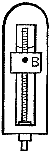
Fig. 1146.
In this case the work must be bolted to the lathe carriage, and the tool feeds to the cut, and the largest end of the hole bored will be at the live spindle end of the lathe.
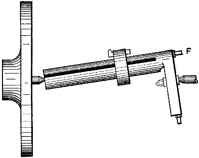
Fig. 1147.
But we may turn the bar around, as in Fig. 1147, driving the work in a chuck, and holding the dead centre end of the bar stationary, feeding the sliding head to the cut by the feed screw f.
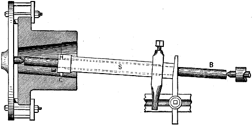
Fig. 1148.
To increase the steadiness of the sliding head it may with advantage, be made long, as in Fig. 1148, in which s is a long sleeve fitting to the bar b at the head end h, and recessed as denoted by the dotted lines. The short cutting tool c may be fastened to h by a set-screw in the end of h, or by a wedge, as may be most desirable. The bar may obviously set over to bore tapers as in the cut, and the sliding head may be prevented from turning by a driver resting on the top of the tool rest, and pushed by a tool secured to the tool post, the self-acting carriage feed being put in operation.
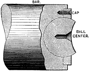
Fig. 1149.
It is obvious that when a boring bar is set over to bore a taper, the lathe centres do not bed fair in the work centres, hence the latter are subject to excessive wear and liable to wear to one side more than to another, thus throwing the bar out of true and altering the taper it will bore. This, however, may be prevented by fitting to the bar at each end a ball-and-socket centre, such as shown in section in Fig. 1149. A spherical recess is cut in the bar, a spherical piece is fitted to this recess and secured therein by a cap as shown, the device having been designed by Mr. George B. Foote.
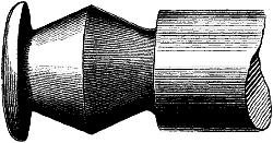
Fig. 1150.
Boring Double Tapers.—To prevent end play in journal bearings where it is essential to do so, the form of journal shown in Fig. 1150 is sometimes employed, hence the journal bearing requires to be bored to fit.
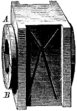
Fig. 1151.
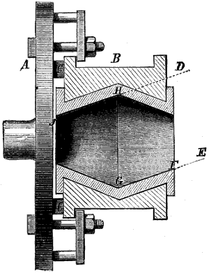
Fig. 1152.
Fig. 1151 represents a bearing box for such a journal, the brasses a, b having flanges fitting outside the box as shown. The ordinary method of doing such a job would be to chuck the box on the face plate of the lathe, setting it true by the circle (marked for the purpose of setting) upon the face of the brasses, and by placing a scribing point tool in the lathe tool post and revolving the box, making the circle run true to the point, which would set the box one way, and then setting the flanges of the box parallel with the face plate of the lathe to set the box true the other way; to then bore the box half way through from one side and then turn it round upon the face plate, reset it and bore the other half; thus the taper of the slide rest would not require altering. This plan, however, is a tedious and troublesome one, because, as the flanges protrude, parallel pieces have to be placed between them and the lathe face plate to keep them from touching; and as the face of the casting may not be parallel with the slide ways, and will not be unless it has been planed parallel, pieces of packing, of paper or tin, as the case may be, must be placed to true the ways with the face plate, and the setting becomes tedious and difficult. But the two tapers may be bored at one chucking, as shown in Fig. 1152, in which a represents the lathe chuck, and b is a sectional view of the bearing chucked thereon, c, c being the parallel pieces. Now it will be observed that the plane of the cone on the front end and on one side stands parallel with the plane of the cone on the back end at an exactly opposite diameter, as shown by the dotted lines d and e. If then the top slide of the lathe rest be set parallel with those lines, we may bore the front end by feeding the tool from the front of the bore to the middle as marked from f to g, and then, by turning the turning tool upside down, we may traverse or feed it along the line from h to j, and bore out the back half of the double cone without either shifting the set of the lathe rest or chucking the box after it is once set.
In considering the most desirable speed and feed for the cutting tools of lathes, it may be remarked that the speeds for boring tools are always less than those for tools used on external diameters, and that when the tool rotates and the work is stationary, the cutting speed is a minimum, rarely exceeding 18 feet per minute, while the feed, especially upon cast iron, is a maximum.
The number of machines or lathes attended by one man may render it desirable to use a less cutting speed and feed then is attainable, so as to give the attendant time to attend to more than one, or a greater number of lathes. In the following remarks outside work and a man to one lathe is referred to.
The most desirable cutting speeds for lathe tools varies with the rigidity with which the tool is held, the rigidity of the work, the purpose of the cut, as whether to remove metal or to produce finish and parallelism, the hardness of the metal and stoutness of the tool, the kind of metal to be cut, and the length the tool may be required to carry the cut without being reground. The more rigid the tool and the work the coarser the feed may be, and the more true and smooth the work requires to be the finer the feed. In a roughing cut the object is to remove the surplus metal as quickly as possible, and prepare the work for the finishing cut, hence there is no objection to removing the tool to regrind it, providing time is saved. Suppose, for example, that at a given speed and feed the tool will carry a cut 12 inches along the work in 20 minutes, and that the tool would then require regrinding, which would occupy four minutes, then the duty obtained will be 12 inches turned in 24 minutes; suppose, however, that by reducing the speed of rotation, say, one-half, the tool would carry a cut 24 inches before requiring to be reground, then the rate of tool traverse remaining the same per lathe revolution, it would take twice as long (in actual cutting time) to turn a foot in length of the work. If we take the comparison upon two feet of work length, we shall have for the fast speed 24 inches turned in 40 minutes of actual cutting time, and 10 minutes for twice grinding the tool, or 24 inches in 50 minutes; for the slow speed of rotation we shall have 24 inches turned in 80 minutes.
In this case therefore, it would pay to run the lathe so fast that the tool would require to be ground after every foot of traverse. But in the case of the finishing cut, it is essential that the tool carry the cut its full length without regrinding, because of the difficulty of resetting the tool to cut to the exact diameter. It does not follow from this that finishing cuts in all cases require to be taken at a slower rate of cutting speed, because, as a rule, the opposite is the case, because of the lightness of the cut; but in cases where the work is long, the rate of cutting speed for the finishing cut should be sufficiently slow to enable the tool to take a cut the whole work length without grinding, if this can be done without an undue loss of time, which is a matter in which the workman must exercise his judgment, according to the circumstances. In tools designed for special purposes, and especially upon cast iron the work being rigid the tool may be carried so rigidly that very coarse feeds may be used to great advantage, because the time that the cutting edge is under cutting duty is diminished, and the cutting speed may be reduced and still obtain a maximum of duty; but the surfaces produced are not, strictly speaking, smooth ones, although they may be made to correct diameter measured at the tops of the tool marks, or as far as that goes at the bottom of the tool marks also, if it be practicable.
In the following table of cutting feeds and speeds, it is assumed that the metals are of the ordinary degree of hardness, that the conditions are such that neither the tool nor the work is unduly subject to spring or deflection, and that the tool is required to carry a cut of at least 12 inches without being reground; but it may be observed that the 12 inches is considered continuous, because on account of the tool having time to cool, it would carry more than the equivalent in shorter cuts, thus if the work was 2 inches long and the tool had time to cool while one piece of work was taken out and another put in the lathe, it would probably turn up a dozen such pieces without suffering more in sharpness than it would in carrying a continuous cut of 12 inches long. The rates of feed here given are for work held between the lathe centres in the usual manner.
CUTTING SPEEDS AND FEEDS.
For Wrought Iron.
Work diameter. Inches. Roughing cuts. Feet per minute. Roughing cuts. Lathe revolutions per minute. Feed as lathe revolutions per inch of tool travel. Finishing cuts. Lathe revolutions per minute. Finishing cuts. Lathe revolutions per inch; tool travel.
1⁄2 40 305 30 305 60
1 35 133 30 133 60
1 1⁄2 30 76 30 76 60
2 28 53 25 53 60
2 1⁄2 28 42 25 42 50
3 28 35 25 35 50
3 1⁄2 26 28 25 30 50
4 26 24 20 26 50
5 25 18 20 21 50
6 25 15 20 16 50
Cast Iron.
1 45 163 30 163 40
1 1⁄2 45 135 25 135 30
2 40 76 25 76 25
2 1⁄2 40 61 20 61 20
3 35 44 20 50 16
3 1⁄2 35 38 18 43 16
4 35 33 18 38 16
4 1⁄2 30 25 16 28 14
5 30 22 16 26 14
5 1⁄2 30 20 14 24 12
6 30 19 14 22 12
Brass.
1⁄2 120 910 25 910 40
3⁄4 110 556 25 556 40
1 100 382 25 382 40
1 1⁄4 90 275 25 275 40
1 1⁄2 80 203 25 203 40
1 3⁄4 80 174 25 174 40
2 75 143 25 143 40
2 1⁄2 75 114 25 114 40
3 70 89 25 89 40
3 1⁄2 70 76 25 76 40
4 70 66 25 66 40
4 1⁄2 65 55 25 55 40
5 65 50 25 50 40
5 1⁄2 65 45 25 45 40
6 65 41 25 41 40
Tool Steel.
3⁄8 24 245 60 245 60
1⁄2 24 184 60 184 60
5⁄8 24 147 50 147 60
3⁄4 24 122 40 122 60
7⁄8 20 87 30 87 60
1 20 76 30 76 60
1 1⁄4 20 61 25 61 50
1 1⁄2 18 45 25 45 50
2 18 34 25 34 50
2 1⁄2 18 27 25 27 50
3 18 22 25 22 40
3 1⁄2 18 19 25 19 40
4 18 17 25 17 40
4 1⁄2 18 15 25 15 40
These cutting speeds and feeds are not given as the very highest that can be attained under average conditions, but those that can be readily obtained, and that are to be found used by skilful workmen. It will be observed that the speeds are higher as the work is smaller, which is practicable not only on account of the less amount of work surface in a given length as the diameter decreases, but also because with an equal depth of cut the tool endures less strain in small work, because there is less power required to bend the cutting, as has been already explained.
When it is required to remove metal it is better to take it off at a single cut, even though this may render it necessary to reduce the cutting speed to enable the tool to stand an increase of feed better than excessive speed. Suppose, for example, that a pulley requires 1⁄4 inch taken off its face, whose circumference is 5 feet and width 8 inches. Now the tool will carry across a cut reducing the diameter 1⁄8 inch, at a cutting speed of 40 feet per minute, or 10 lathe revolutions per minute; but if the speed be reduced to about 35 feet per minute, the tool would be able to stand the full depth of cut required, that is, 1⁄8 inch deep, reducing the diameter of the pulley 1⁄4 inch. Now with the fast speed two cuts would be required, while with the slow one a single cut would serve; the difference is therefore two to one in favor of the deep cut, so far as depth of cut is concerned.
The loss of time due to the reduced rotative speed of work would of course be in proportion to that reduction, or in the ratio of 35 to 50. It is apparent then that the tool should, for roughing cuts, be set to take off all the surplus metal at one cut, whenever the lathe has power enough to drive the cut, and that the cutting speed should be as fast as the depth of cut will allow.
Concerning the rate of feed, it is advisable in all cases, both for roughing and finishing cuts, to let it be as coarse as the conditions will permit, the rates given in the table being in close approximation of those employed in the practice of expert lathe hands.
It is to be observed, however, that under equal conditions, so far as the lathe and the work is concerned, it is not unusual to find as much difference as 30 per cent. in the rate of cutting speed or lathe rotation, and on small work 50 per cent. in the rate of tool traverse employed by different workmen, and here it is that the difference is between an indifferent and a very expert workman.
An English authority (Mr. Wilson Hartnell), who made some observations (in different workshops and with different workmen) on this subject, stated that taking the square feet of work surface tooled over in a given time, he had often found as much as from 100 to 200 per cent. difference, and that he had found the rate of tooling small fly-wheels vary from 2 to 8 square feet per hour without any sufficient reason. The author has himself observed a difference of as much as 20 feet of work rotation per minute on work of 18 and less inches in diameter, and as much as 50 per cent. in the rate of tool traverse per lathe revolution.
It is only by keeping the speed rotation at the greatest consistent with the depth of cut, and by exercising a fine discretion in regulating the rotations of feed and cutting speed, that a maximum of duty can under any given conditions be obtained.
It has hitherto been assumed that the workman’s attention is confined to running one lathe, but cases are found in practice where the lathes, having automatic feed and stop motions, one man can attend to several lathes, and in this case the feeds and speeds may be considerably reduced, so as to give the operator time to attend to a greater number of lathes. As an example, in the use of automatic lathes, several of which are run by one man, the following details of the practice in the Pratt and Whitney Company’s tap and die department are given.
Lathe Number 1.—Lathe turning tool steel 3⁄8 inch in diameter and 11⁄4 long, reducing the diameter of the work 1⁄8 inch. Revolutions of work per minute 125. Feed one inch of tool travel to 200 lathe revolutions.
Lathe Number 2.—Turning tool steel 2 inches long and 1⁄2 inch diameter, reducing diameter 1⁄8 inch. Revolutions of work 100 per minute. Feed 200 lathe revolutions per inch of tool travel.
Lathe Number 3.—Turning tool steel 4 inches long and 7⁄8 inch in diameter, reducing the diameter 1⁄8 inch. Revolutions of work 40 per minute. Feed 200 lathe revolutions per inch of tool travel.
Lathe Number 4.—Turning tool steel 6 to 8 inches long and 13⁄16 diameter, reducing work 1⁄8 inch in diameter. Revolutions of work 35 per minute. Feed 200 lathe revolutions per inch of tool travel.
Lathe Number 5.—Turning tool steel 8 to 10 inches long, and 2 inches in diameter, reducing diameter 1⁄8 inch. Lathe revolutions 30 per minute. Feed 200 lathe revolutions per inch of tool travel.
Lathe Number 6.—Turning tool steel 5 inches long and 31⁄2 inches diameter, reducing diameter 3⁄16. Lathe revolutions 19 per minute. Feed 200 lathe revolutions per inch of tool travel.
The power required to drive the work under a given depth of cut varies greatly with the following elements:—
1st. The diameter of the work, all other conditions being equal.
2nd. The degree of hardness of the metal, all other conditions being equal.
3rd. Upon the shape of the cutting tool; and—
4th. Upon the quality of the steel composing the cutting tool, and the degree of its hardness.
That the diameter of the work is an important element in small work may be shown as follows:—
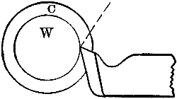
Fig. 1153.
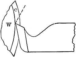
Fig. 1154.
In Fig. 1153 let w represent a piece of work having a cut taken off it, and the line of detachment of the metal from the body of the work will be represented by the part of the dotted line passing through the depth of the cut (denoted by c). Let Fig. 1154 represent a similar tool with the same depth of cut on a piece of work of larger diameter, and it will be observed that the dotted line of severance is much longer, involving the expenditure of more power.
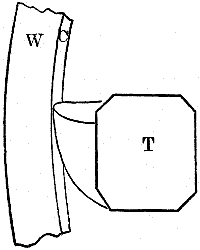
Fig. 1155.
In boring these effects are magnified: thus in Fig. 1155 let w represent a washer to be bored with the tool t, and let the same depth of cut be taken by the tool, the diameter of the work being simply increased. It is manifest that the cutting would require to be bent considerably more in the case of the small diameter of work than in that of the large, and would thus require more power for an equal depth of cut.
Again, from a reference to Figs. 950 and 952, it will be observed that the height of the tool will make a difference in the power required to drive a given depth of cut, the shaving being bent more when the tool is above the centre in the case of boring tools, and below the centre in the case of outside tools. But when the diameter of the work exceeds about 6 inches, it has little effect in the respects here enumerated.
The following, however, are the general rules applicable when considering the power required for the cutting of metal with lathe or planer tools. The harder the metal, the more power required to cut off a given weight of metal. The deeper the cut the less power required to cut off a given weight of metal. The quicker the feed the less power required to cut off a given weight of metal. The smaller the diameter of outside work, and the larger the diameter of inside or bored work, the less power required.
Copper requires less power than brass; yellow, and other brass containing zinc, less than brass containing a greater proportion of tin. Brass containing lead requires less power than that not containing it. Cast iron requires more power than brass, but less than wrought iron; steel requires more power than wrought iron.