Volume 1 / Part 3 — PART THIRD. PHYSICAL PROPERTIES OF SOILS. (continued 2)
Reading edition
149. Accuracy of Results.—A sample of soil from the beet sugar station, in Nebraska, gave the following duplicate results:
First trial 45.75 per cent water.
Second trial 44.85 „ „ „
Muck soils from Florida, containing varying proportions of sand, gave the following numbers:
Soil number one, 144.85 per cent, and 145.43 per cent; soil number two, 109.13 per cent, and 107.93 per cent; soil number three (very sandy), 46.86 per cent, and 46.51 per cent.
137150. Method of Wollny.[105]—A zinc tube, ninety centimeters long and four centimeters internal diameter, carries at each end, at right angles to the axis, a flattened rim 1.5 centimeters broad. The lower end of the tube is closed with a strong piece of coarse linen. The soil to be examined is then filled in little by little, with gentle tamping.
On the upper end two glass tubes are placed, each ten centimeters long and four centimeters internal diameter. These tubes are furnished at each end with cemented brass cylinders which are expanded to a circular, evenly ground rim, 1.5 centimeters wide, also at right angles to the axis of the main tube. These rims are greased and placed together, one on the other, and held together by wooden clamps.
The glass tube in immediate connection with the zinc tube is also firmly filled with the soil sample, while the second tube is only partly filled, so that any settling which may take place in the soil on the addition of water may still find the first glass tube full of the sample.
The empty part of the upper glass tube is now filled with water and additional quantities of water are added from time to time until the soil is saturated. In order to be able to observe when this takes place there is a slit at the lower end of the zinc tube which is closed with a piece of glass. This slit should be about two centimeters broad and ten centimeters long. The lower end of the zinc tube is set on a glass plate to prevent evaporation.
As soon as the water shows itself at the lower end of the zinc tube, the excess of water in the upper glass tube is at once removed by a pipette and a stopper inserted through which a glass tube passes drawn out into a fine point above. The object of this is to avoid evaporation on the upper surface. The apparatus is then left at rest for thirty-six hours.
At the end of this time the clamps are removed and the column of moist earth cut with a piece of platinum foil, and the two ends of the glass tube, next to the zinc tube, covered with glass plates. It is then weighed and the weight of moist earth determined by deducting the weight of the tube and its glass covers. The moist earth is carefully removed to a large porcelain dish and dried at 100°. Before weighing it is allowed to stand twenty-four 138hours in the air. The data obtained are used to calculate the water content to volume per cent.
The volume of the glass tubes should be determined by careful calibration.
151. Method of Heinrich.[106]—The soil to the depth turned by the plow is dug out and in the hole a lead vessel without bottom, twenty centimeters in diameter and forty centimeters high, is placed. The soil is then thrown back around and outside the lead vessel until the latter appears buried in the fragments.
The rest of the soil is passed into the lead vessel, through a sieve having four meshes to the centimeter, using for this purpose enough water to thoroughly moisten it. Care should be taken not to use enough water to cause any separation of the fine from the coarse particles.
By this process all coarse stones, sticks, etc., are separated. In sandy soils the flask is left for a few hours while in clay soils a much longer time is necessary. When the excess of water has disappeared the lead cylinder is removed, and a piece cut out of the center of it placed in a weighed drying flask and dried at 100°.
152. Effect of Pressure on Water Capacity.[107]—The increasing capacity of soil to hold water developed by shaking or pressure, is determined by Henrici in the following way:
Into a glass cylinder of twenty millimeters internal diameter are poured twenty cubic centimeters of water. A given quantity of soil is next added, and after standing until thoroughly saturated, the residual water is measured by pouring off, or better, by graduations on the side of the tube. The increase in the volume of the clear water is also measured, after shaking, in the same way. The data of a determination made as above described follow:
Water in cylinder 30 cubic centimeters.
Water and saturated soil 40 „ „
Volume of unsaturated soil = e = 10 „ „
Volume of saturated soil = e + w = 20.5 „ „
Water contained therein = w = 10.5 „ „
By repeated shaking the volume of e + w, the content of w therein, and the relative values of e w were found to be as follows:
139
Cubic centimeters. Cubic centimeters. Cubic centimeters. Cubic centimeters.
e + w 20.5 16.0 15.7 15.0
w 10.5 6.0 5.7 5.0
w e 1.05 0.60 0.57 0.50
If e′ represent the volume of the saturated soil then e′ = e + w, and this gives the relation to the volume of dry earth represented by the equation e′ e = 1 + w e. This indicates that the relative volume of the saturated soil is equal to unity increased by the relative content of water.
153. Coefficient of Evaporation.—At an ordinary room temperature in the shade, samples of soil, if they are subjected to experiment in tolerably thin layers have nearly an equal coefficient of evaporation. That is, the absolute quantity of water evaporated in a given time is almost entirely conditioned upon the magnitude of the surface exposed and the temperature of the surrounding air. Only when exposed in conditions as nearly as possible natural in thin layers to the action of the sunlight and shade do the soils show their peculiarities in respect of the evaporation of moisture. In order to see these peculiarities, samples of soil which have been previously examined must be subjected to examination at the same time with the soil whose properties are to be determined.
The zinc box, before described, should be protected with a well fitting cover of thick paper, and the different samples of soil which are to be tested placed therein. This should now be placed in a wooden box, the top of which is exactly even with the top of the zinc vessel. This box containing the vessel should be exposed to the sunlight. After twenty-four hours the zinc boxes can be taken away from position and their loss in moisture determined, and these weighings, according to the condition of the atmosphere, can be continued from fourteen days to three weeks, the temperature of the air of course being carefully determined at each time. At first, all the different soils being saturated with moisture, it will be observed that the loss of moisture is proportionately the same for all. Soon, however, the rapidity of the evaporation in the samples of soil rich in humus and clay will be decreased as compared with the sandy 140soils, and in general, those which possess a high capillary power capable of bringing the moisture rapidly from the deeper layers to the surface. There soon comes a point when the difference in evaporation is at its greatest; and then there will be a gradual diminution until the samples lose no further moisture. This point, for the different soils, can be determined by frequent weighings of the vessel.
154. Determination of Capillary Attraction.—Long glass tubes graduated in centimeters may be used for this determination, or plain tubes so arranged as to admit of easy measurements with a rule. The tubes may be from one to two centimeters internal diameter and about one meter long. The fine earth should be evenly filled in little by little, with gentle jolting. The lower end of each tube, before filling, is closed with a piece of linen.
The tubes, after filling, are supported in an upright position by a frame AE, Fig. 19, in a vessel B containing water in which the linen covered ends D dip to the depth of two centimeters. The height of the water in the several tubes should be read or measured at stated intervals. The water contained in the supply vessel should be kept at a constant height by a Mariotte bottle.
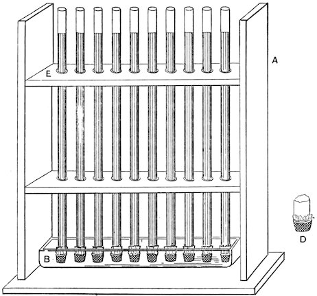
Figure 19. Apparatus to show Capillary Attraction of Soils for Water.
The observations may be discontinued after one hundred and twenty hours, but even then the water will not have reached its maximum height.
It is recommended by some experimenters to cut the tubes, 141after the above determination is completed, into pieces ten centimeters in length, and to determine the per cent of water in each portion.
155. Statement of Results.—The following table illustrates a convenient method of tabulating the observed data as given by König.[108]
Number of sample 1 2 3 4 5 6
Height of moisture column after: 24 hours. 27.3 38.0 16.7 36.4 8.0 28.8 centimeters.
48 „ 35.9 50.8 24.5 49.2 11.9 40.5 „
72 „ 41.5 59.5 30.0 57.9 15.2 49.1 „
96 „ 44.4 66.2 33.5 63.8 17.5 55.2 „
120 „ 46.7 70.0 36.3 68.5 19.2 60.5 „
156. Inverse Capillarity.—In tubes filled with fine earth, as described in paragraph 154, water is quickly poured, the same quantity into each tube of the same diameter, or such quantities in tubes of different diameters as would form a water column of the same depth over the surface of the sample. The rate at which the water column descends in each tube, the time of the disappearance of the water at the surface and the final depth to which it reaches, are the data to be entered.
157. Statement of Results.—The points to be observed in the determination of inverse capillarity are the number of hours required for the total absorption of a column of water of a given height, the depth of the moisture column at that moment, and the total depth to which the moisture column finally reaches. The data of observations with six samples with a water column four centimeters high are given by König[109] as follows:
Number of sample 1 2 3 4 5 6
Number of hours required for water to disappear 4.3 1.8 10.3 3.0 21.0 4.3
Depth of moisture at time of disappearance of water 11.0 12.0 11.4 13.3 11.7 12.0 centimeters.
Total depth of moisture 13.0 18.1 13.0 19.0 12.0 16.5 „
158. Determination of the Coefficient of Evaporation.—The coefficient of evaporation is the number of milligrams of water evaporated from a square centimeter of soil surface in a 142given unit of time. It is evident that this number will vary with the physical state of the soil, the velocity of the wind, the saturation of the air with aqueous vapor and the temperature. In all statements of analyses these factors should appear.
The process may be carried on first (a) with soil samples kept continually saturated with water and (b) with samples in which the water is allowed to gradually dry out.
Method a.—The determination may be made in the shade or sunlight.
In the Shade.—A zinc cylinder (Z Fig. 20), fifteen centimeters in diameter and 7.5 centimeters high, with a rim one centimeter wide and one centimeter from top, is covered at one end with linen or cotton cloth and filled with fine earth, with gentle jolting, until even with the top. It is then placed in a zinc holder H, into the circular opening of which it snugly fits as in A. This holder is twenty centimeters in diameter and 7.5 centimeters deep. It has an opening at O through which water can be added until it is filled so as to wet the bottom of Z when in place. As the water is absorbed by the soil more is added and, the top being covered, the apparatus is allowed to stand for twenty-four hours. At the end of this time the soil in the zinc cylinder is saturated with water to the fullest capillary extent.
The whole apparatus, after putting a stopper in O, is now weighed on a large analytical balance and placed in an open room, with free-air circulation, for twenty-four hours. At the end of this time it is again weighed and the loss of weight calculated to milligrams per square centimeter. Where large and delicate balances can not be had, the apparatus can be constructed on a smaller scale suitable for use with a balance of the ordinary size.
In the Sunlight.—The apparatus described above is enclosed in a wooden box having a circular opening the size of the soil-zinc cylinder. In the determination of the rate of evaporation, the apparatus, charged and weighed as above described, is exposed to the sun for a given period of time, say one hour. On the second weighing the loss represents the water evaporated. The time of year, time of day, velocity of wind and temperature, 143and degree of saturation of the air with aqueous vapor, should be noted. The data obtained can then be calculated to milligrams of water per square centimeter of surface for the unit of time.
Method b.—As in method a the determination may be made in the shade or in the sunlight. The rate of evaporation is, in this method, a diminishing one and depends largely on the reserve store of water in the sample at any given moment.
The same piece of apparatus may be used as in the determinations just described. After charging the sample with moisture all excess of water in the outer zinc vessel is removed and the rate of evaporation determined by exposure in an open room or in the sunlight, as is done in the operations already described.
Alternate Method.—The zinc cylinders used in determining saturation coefficient, paragraph 145, may also be employed in determining the rate of evaporation. Each cylinder should be wrapped with heavy paper or placed in a thick cardboard receptacle, and all placed in a wooden box, the cover of which is provided with circular perforations, just admitting the tops of the cylinders, which should be flush with the upper surface of the cover.
Arranged in this way the cylinders previously weighed are exposed in the shade or to direct sunlight and reweighed after a stated interval. On account of the small surface here exposed in comparison with the total quantity of soil and moisture it is recommended to weigh the cylinders once only in twenty-four hours. The weighings may be continued for a fortnight or even a month.
In soils fully saturated with water the rate of evaporation is at first nearly the same on account of the surface being practically that of water alone. As the evaporation continues, however, the rate changes markedly with the character of the soil.
159. Rapid Method of Wolff.—In order to expose a larger surface to evaporation and to secure the results in a shorter period of time, Wolff[110] fills square boxes, having wire-gauze bottoms, with fine earth, and after saturating with moisture weighs and suspends them in the open air. The wire-gauze bottoms are previously covered with filter paper to prevent loss of soil.
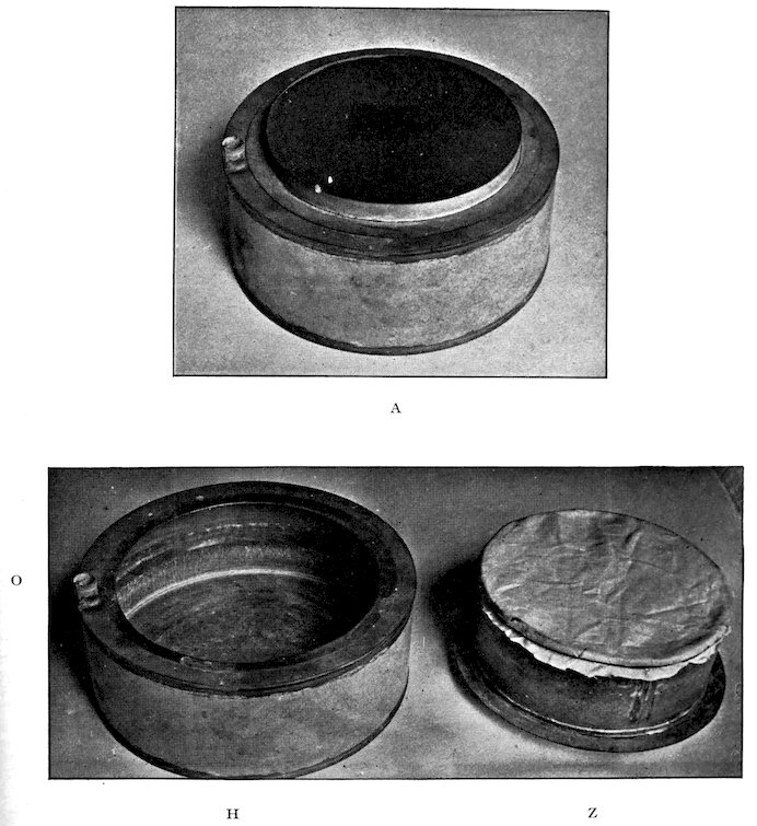
Figure 20. Apparatus for Determining Coefficient of Evaporation.
144160. Estimation of Water Given up in a Water-Free Atmosphere.—The air-dried sample, in quantities of from five to ten grams in a thin layer on glass, is placed over a vessel containing strong sulfuric acid. It is then placed on a ground glass plate and covered with a bell jar. The sample is weighed at intervals of five days until the weight is practically constant.
This method is valuable in giving the actual hygroscopic power of a soil depending on its structure alone.
161. Estimation of the Porosity of the Soil for the Passage of Gases.—Some further notion of the physical state of the soil known as porosity, may also be derived by a study of the rate at which it will admit of the transmission of gases. A method for estimating this has been devised by Ammon.[111]
Air is compressed in two gas holders by means of a column of water of proper height to give the pressure required.
The tubes through which the air passes out of the gas holders are each furnished with a stop-cock and united with a glass tube having a side tube set in at right angles for carrying off the air.
The use of two holders makes it possible to carry on the experiment as long as may be desired, one holder being filled with air while the other is emptying.
The common conducting tube is joined with a meter which is capable of measuring, to 0.01, the volume of air passing through it. The pressure is regulated by means of the stop-cocks. The air passing from the meter is received in a drying tube filled with calcium chlorid.
From the drying tube the air enters a drying flask filled below with concentrated sulfuric acid and above with pumice stone saturated therewith. Next the dried air passes through a worm, eight meters long, surrounded with water at a given temperature. The dried air of known temperature next enters the experimental tube. This tube is made of sheet zinc 125 centimeters in length and five centimeters in internal diameter. It is placed in an upright position, and about six centimeters from its upper end carries a small tube at right angles to the main one for connection with a water-filled manometer.
The upper and lower ends of the tube are closed with perforated rubber stoppers carrying tubes for the entrance and exit of the air.
145In the inside of the zinc tube are found two close-fitting but movable disks, of the finest brass wire gauze, between which the material to be experimented upon is held.
The layer of fine soil is held between these disks and may be of such a depth as is required for the proper progress of the experiment. With soils of firm texture opposing a great resistance to the passage of the air the column of earth tested should be shorter than with light and very permeable soils. The experimental tube is surrounded with a water jacket, which may also be made of sheet zinc, carrying small tubes directed upwards for holding thermometers. The water jacket should be kept at the same temperature as the air which is used in the experiment.
The process of filling the tube, the amount of pressure to be used and the air and soil temperature, will naturally vary in different determinations.
The volume of air at a given pressure and temperature which passes a column of soil of a given length in a unit of time will give the coefficient of permeability.
162. Determination of Permeability in the Open Field.—A method for determining the rate of transmission of a gas through the soil in the field has been devised by Heinrich.[112]
A box C (Fig. 21) is made of strong sheet iron and has an opening below, ten centimeters square, and a height of about twenty centimeters. At exactly ten centimeters from the bottom, the box has a rim at right angles to its length so that it can be placed only ten centimeters deep in the soil. The box holds a volume of earth equal to 1,000 cubic centimeters.
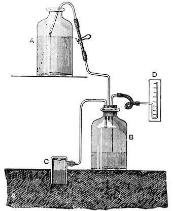
Figure 21. Method of Heinrich.
The part of the box above ground is connected with the bottle B by a glass tube as indicated in the figure. The 146bottle B should have a capacity of about ten liters. The air in B is forced out through C by water running in from the supply A and the pressure in B is recorded by the manometer D. The experiment should be tried on a soil thoroughly moist.
In measuring the pressure in B the water pressure should be cut off by the pinch-cock between A and B, and the pressure on the manometer observed after the lapse of one to two minutes.
MOVEMENT OF WATER THROUGH SOILS: LYSIMETRY.
163. Porosity in Relation to Water Movement.—The intimate relation which water movement in a soil bears to fertility makes highly important the analytical study of this feature of porosity. A soil deficient in plant food, in so far as chemical analysis is concerned, will produce far better crops when the flow of moisture is favorable than a highly fertile soil in which the water may be in deficiency or excess.
Aside from the actual rain-fall the texture of the soil, in other words its porosity, is the most important factor in determining the proper supply of moisture to the rootlets of plants. Even where the rain-fall is little, a properly porous soil in contact with a moist subsoil will furnish the moisture necessary to plant growth. This fact is well illustrated by the beet fields in Chino Valley, California. In this locality most excellent crops of sugar beets are produced without irrigation and almost without rain.
164. Methods of Water Movement—The translocation of soil water is occasioned in at least two ways; namely,
1. By changing the porosity of a given stratum of soil.
2. By changing the amount of water a given stratum contains.
The following experiment by King[113] illustrates a convenient method of studying this movement of water:
On a rich fallow ground of light clay soil, underlaid at a depth of eighteen inches by a medium-grained sand, water, to the amount of two pounds per square foot on an area of eight by eight feet, was slowly added with a sprinkler, samples of soil having been previously taken in six-inch sections down to a depth of 147three feet. The samples were taken along a diagonal of the square under experiment and one foot apart. The middle sample of the line being from the center of the area. The sampling and wetting occurred between one and three P. M., on July 22, and on the evening of the 23 a corresponding series of samples was taken along a line parallel to the first but eight inches distant. The changes in the percentages of water in the soil are given in the following table, showing the translocation of water in soil due to wetting the surface:
PER CENT OF WATER. DIFFERENCE.
Inches. Before wetting. After wetting. In per cent. In pounds per cu. ft.
0–6 14.00 22.23 +8.23 +2.873
6–12 15.14 15.71 +0.57 +0.199
12–18 16.23 15.75 –0.48 –0.213
18–24 17.70 16.92 –0.78 –0.347
24–30 16.76 14.41 –2.35 –1.032
30–36 15.51 15.21 –0.30 –0.132
The figures given in the last column of the table are computed from the absolute dry weights of the upper three feet of soil as determined in a locality some rods from the place of experiment, and are therefore only approximations, but the error due to this cause is certainly small. It will be seen that while only two pounds of water to the square foot were added to the surface, the upper six inches contained 2.87 pounds per square foot more than before the water was added, and the second six inches contained 0.199 pound more, and this too in the face of the fact that the evaporation per square foot from a tray sitting on a pair of scales close by, was 0.428 pound during the interval under consideration. Similar experiments were made by taking the samples of soil at 5.30 P. M. in one-foot sections down to four feet, at four equally distant places along the diagonal of a square, six by six feet, and having the ground sprinkled. At the same time four similar sets of samples were taken on lines vertical to each of the sides of the square but four feet distant from them. The amount of water the soil contained was then determined, and at 11.30 A. M., nineteen hours later, another series of samples was taken at points about four inches distant from the last and the amount of water determined with the result given below.
148
Translation of Water Occasioned by Wetting the Surface.
Depth of samples. WET AREA. AREA NOT WET.
Before wetting. After wetting. First samples. Second samples.
Per cent of water. Pounds of water per cubic foot. Per cent of water. Pounds of water per cubic foot. Per cent of water. Pounds of water per cubic foot. Per cent of water. Pounds of water per cubic foot.
0–12 inches 16.86 11.78 20.15 14.06 17.72 12.38 18.27 12.75
12–24 „ 17.76 15.79 19.71 17.52 19.18 17.05 19.94 17.72
24–36 „ 16.76 14.73 17.72 15.58 16.97 14.92 17.52 15.40
36–48 „ 15.01 14.03 16.47 15.40 15.49 14.48 15.16 14.17
Averages 16.59 14.08 18.51 15.64 17.34 14.71 17.71 15.01
Total amount of water 56.33 62.56 58.83 60.04
Amount of change +6.23 +1.21
The above data show sufficiently well the method of investigation to be pursued in studies of this kind.
165. Capillary Movement of Water.—The method of investigation proposed by King[114] consists in taking samples of soil at intervals of one, two, three, or four feet in depth, and determining the amount of moisture in each in connection with the amount of rain-fall during the period. The quantity of water contained in a given soil, at various depths and on different dates, is shown in the following table:
Depth in feet. Date. Per cent water. Pounds per cubic foot. Increase or decrease. Pounds per cubic foot.
1 March 8th 24.33 16.98
1 April 18th 22.37 15.61 –1.37
2 March 8th 15.80 14.05
2 April 18th 21.64 19.24 +5.19
3 March 8th 11.16 9.81
3 April 18th 16.24 14.27 +4.46
4 March 8th 7.87 7.36
4 April 18th 11.19 10.46 +3.10
The rain-fall during the interval was 4.18 inches, equal to 21.77 pounds per square foot.
166. Lateral Capillary Flow.—To determine the lateral capillary flow of water in a soil the following method, used by King[115] may be employed:
A zinc lined tray, six by six feet in area and eight inches deep, 149is filled with a soil well packed. In one corner of this tray a section of five inches of unglazed drainage tile, having its lower end broken and jagged, is set and the dirt well filled in round it. By means of a Mariotte bottle water is constantly maintained in the bottom of this tile, three-quarters of an inch deep, so that it will flow laterally by capillary action into the adjacent soil, the object being to determine the extent and rate of capillary flow laterally.
The water content of the soil is determined at the time of starting the experiment, on the circumferences of circles described with the tile as a center, the distance between the circles being one foot. At stated periods, usually at intervals of one day, the content of moisture is again determined at the same points. The investigations show that the lateral movement of water in the soil is not rapid enough to extend much beyond three feet in thirty-one days, for beyond that distance the soil was found to be drier than at the beginning of the experiment. A record is to be kept of the amount of water delivered to the soil by weighing the supply bottle at intervals, and the rates given at which the soil takes up the water in grams per hour and pounds per day. Also the amount of flow per square foot of soil section together with the mean daily evaporation should be noted. The mean flow per foot of soil section is computed on the assumption that the outer face of the zone of completely saturated soil is the delivering surface. In King’s work this point, as nearly as could be determined, was twelve inches from the corner of the tray and hence the figures at best can only be regarded as approximations. The method of stating results is shown in the following table:
Showing the Rate of Lateral Capillary Flow of Water in Clay Loam.
Date. No. of days. Total mean, hourly flow, grams. Total mean, daily flow, pounds. Mean daily flow per square foot, pounds. Mean daily evaporation, pounds.
Jan. 28 to Feb. 2 5 70.70 3.73 2.38
Feb. 2–7 5 85.98 4.54 2.91
Feb. 7–12 5 79.33 4.19 2.64
Feb. 12–17 5 79.41 4.19 2.64 0.598
Feb. 17–22 5 70.79 3.74 2.38 0.534
Feb. 22–28 6 59.89 3.16 2.01 0.451
Feb. 28 to March 6 6 60.74 3.21 2.04 0.458
Mar. 6–13 7 60.37 3.14 2.00 0.448
Means 2.38 0.498
150From this table it will be seen that the flow of water in the soil varied in rate, being slower during the first five days than in the succeeding fifteen days. After twenty days the flow dropped again to the beginning rate and then fell below, but remained quite constant during the following nineteen days. For the sake of uniformity in units of measure the daily quantity of flow should be given in kilograms when the hourly flow is given in grams.
167. Causes of Water Movement in the Soil.—The movement of water in a soil as explained by Whitney[116] is due to two forces, viz., gravitation and surface tension.
The force of gravitation in a given locality is always uniform, both in direction and magnitude per unit volume of water.
Surface tension is the tendency of any exposed water surface to pull itself together. It may act in any direction, according to circumstances, and may thus sometimes help and sometimes antagonize the force of gravitation.
According to the law of surface tension any particle of moisture tends to assume the smallest possible area. This tendency is a constant definite force per unit of surface at a given temperature. In the soil this constant strain on the free surface of water particles serves, in a high degree, to move them from place to place, in harmony with the requirements of the different portions of the field.
When a soil is only slightly moist the water clings to its grains in the form of a thin film. When these soil particles are brought together the films of water surrounding them unite, one surface being in contact with the soil particles and the other exposed to the air. If more water enter the soil the film thickens until finally, when the point of saturation is reached, all the space between the soil particles becomes filled with water, and surface tension within the soil is thus reduced to zero. Gravity then alone acts on the water and with a maximum force.
In a cubic foot of ordinary soil the total surface of the soil particles will be at least 50,000 square feet. It follows that when the soil is only slightly moist the exposed water surface of the films surrounding the soil particles approximates that of the particles themselves. If such a mass of 151slightly moist soil be brought in contact with a like mass saturated with water, the films of water at the point of contact will begin to thicken in the nearly dry soil at the expense of the water content of the saturated mass. The water will thus be moved in any direction.
During evaporation the surface tension near the surface of the soil is increased, and water is thus drawn from below. In like manner, when rain falls on a somewhat dry soil, the surface tension is diminished and the greater surface tension below pulls the moisture down even when gravitation would not be sufficient for that purpose.
Certain fertilizers have the faculty of modifying surface tension and thus change the power of the soil in its attraction for moisture. In this way such fertilizers act favorably on plant growth, both by providing plant food and by supplying needed moisture.
168. Surface Tension of Fertilizers.—Whitney gives the following data in respect of the surface tension of aqueous solutions of some of the more common fertilizing materials. It is expressed in gram meters per square meter, i. e., on a square meter of liquid surface there is sufficient energy to lift the given number of grams to the height of one meter.
Surface Tension of Various Fertilizing Solutions.
Solution of— Specific gravity. Gram meters per square meter.
Salt 1.070 7.975
Kainite 1.053 7.900
Lime 1.002 7.696
Water 1.000 7.668
Acid phosphate 1.005 7.656
Plaster 1.000 7.638
Ammonia 0.960 6.869
Urine 1.026 6.615
Magnesium chlorid 1.1000 7.964
Basic slag 1.0012 7.890
Marl 1.0013 7.855
Potassium chlorid 1.1000 7.853
Ammonium sulfate 1.1000 7.834
Dried blood 1.0001 7.764
Ground bone 1.0007 7.749
Sodium nitrate 1.1000 7.730
Sodium sulfate 1.1000 7.730
152Wood ashes 1.0038 7.674
Potassium nitrate 1.1000 7.661
Potassium sulfate 1.0830 7.658
Ammonium nitrate 1.1000 7.656
Dried fish 1.0026 7.594
Stable manure 1.0013 7.464
Cotton-seed meal 1.0054 6.534
Tankage 1.0169 4.844
Cotton seed 1.0070 4.788
Surface Tension of Soil Extracts.
Kind of Soil. Specific gravity. Surface tension.
Kentucky blue grass 1.000 7.244
Triassic red sandstone 1.000 7.244
Wheat soil 1.000 7.098
Garden soil 1.000 7.089
169. Method of Estimating Surface Tension.—The determination of surface tension is made by measuring the rise of the liquid in a capillary tube. A short piece of thermometer tubing is used, the diameter of the bore being determined by careful microscopic measurements with a micrometer eyepiece. The diameter of the tube should be about 0.5578 millimeter. The tube is very thoroughly cleaned after each observation, or set of observations, with a strong caustic potash solution, and, after washing, is allowed to stand for some time in a saturated solution of potassium bichromate in strong sulfuric acid. The height of the rise in the capillary tube is measured with a cathetometer.
The following formula is used for the calculation of the results:
T = h d ω 4 cos. a
Where T is the surface tension, d is the diameter of the tube in centimeters; h the height to which the liquid rises in the capillary tube in centimeters; ω is the specific gravity of the solution; and 4 cos. a refers to the angle of the liquid with the sides of the glass tube. For a tube of the size given above, 5° 24′ is the value of this edge angle. In regard to saline solutions, Quincke[117] says, that the edge angle appears to increase a little with augmenting concentration of the saline solution, but otherwise 153to differ only inconsiderably from the edge angle of pure water.
170. Effect of the Solutions on Surface Tension.—The mineral fertilizers, as a rule, increase the surface tension of water, while organic matters in solution decrease it. But it must not be forgotten in this connection that but little of the organic matter in the fertilizers employed for the experiment passes into solution. Moreover, with these substances, the accuracy of the work is impaired somewhat by the increased viscosity. In general, the results of the experiment are in harmony with the well-known effect of magnesium, sodium, and potassium chlorids, and sodium nitrate, to make the soil more moist in dry weather, and the opposite effect produced by the application of organic matter.
171. Method of Preparing Soil Extracts.—The soil extracts used in determining the surface tension, as given in the above table, are prepared as follows:
Ten grams of the soil are rubbed up with fifteen to twenty cubic centimeters of distilled water and allowed to stand for twenty-four hours with frequent stirring. Any fine particles not removable by a filter are neglected, although they may give a turbid appearance to the solution.
172. Lysimetry.—The process of measuring the capacity of a soil to permit the passage of water and of collecting and determining the amount of flow and determining soluble matters therein is known as lysimetry. In general, the rate at which water will pass through a soil depends on the fineness and approximation of its particles. Water will pass through coarse sand almost as rapidly as through a tube, while a fine clay may be almost impervious. The study of the phenomena of filtration through soil, and the methods of quantitatively estimating them, are therefore closely related to porosity.
Two cases are to be considered, viz.: First, percolation through samples of soil prepared for analysis, and second, the passage of the water through soil in situ, whether it be virgin or cultivated.
The determination of the rate of flow through a soil in laboratory 154samples, gives valuable information in respect of its physical properties, while the same determination made on the soil in situ, has practical relations to the supply of moisture, to growing plants, and the waste of valuable plant food in the drainage waters. The determination of the rate of flow of water through a small sample, disturbed as little as possible in its natural condition, is classed with the first divisions of the work, inasmuch as the removal of a sample of soil from a field, and its transfer to the laboratory, subjects it to artificial conditions, even if its texture be but little disturbed by the removal.
173. Calculation of the Relative Rate of Flow of Water Through Soils.—There will evidently be one space, or opening, into the soil for every surface grain, as pointed out by Whitney,[118] and the approximate number of grains, or of openings, on a unit area of surface may be found by the following formula:
N = (√(M × W V)⅔
where N is the number of grains, or openings, on one square centimeter of surface, M is the approximate number of grains in one gram of soil, W is the weight of soil, V is the total volume of the soil grains and the empty space.
If the grains are assumed to be symmetrically arranged and the spaces between them cylindrical in form, the radii of the spaces can be found by the following formula:
r = √V₁ πNL
where r is the radius of a single space, V is the total volume of the empty space, N is the number of grains or spaces on one square centimeter of surface, and L is the depth of the soil.
If the space within the soil is completely filled with water the relative rate of flow of water through the soil will be according to the fourth power of the radius of a single space multiplied by the number of spaces on the unit area of surface, as shown by the following formula:
T₁ = N(r)⁴T N₁(r₁)⁴
where N-N₁ are the numbers of spaces, and r-r₁ are the radii 155of single spaces in the respective soils, and T-T₁ the times required for a unit volume of water to flow through the soils under the same head or pressure.
The space within the soil is rarely filled with water in agricultural lands, and the most favorable amount of water for the soil to hold, as Hellriegel and others have shown, is from thirty to fifty per cent of the total amount of water the soil can hold if all the space within it were filled.
If the space within the soil be only partly filled with water, as in most arable lands, the water will move in a thin film surrounding the soil grains and according to the fourth power of the thickness of the film. The mean thickness of the film surrounding the soil grains may be theoretically determined by the following formula, which is based on the conception that the film is cylindrical and of uniform size throughout:
t = r(1 − √s s + p)
where s is the per cent by weight of water which the soil will hold when the empty space is filled with water, p the per cent of water actually contained in the soil, r the radius of a single space, and t the mean thickness of the film surrounding the soil grains.
The relative rate of flow of water through the soils will then be according to the following formula:
T₁ = N(t)⁴T N₁(t)₁⁴)
It must be remembered that these formulæ give only approximate and comparative values for comparing one soil with another. The structure of the soil is altogether too intricate to expect ever to obtain absolute values.
If the observed rate of flow varies widely from the relative rate calculated from the mechanical analysis, it will indicate a difference in the arrangement of the soil grains, or in the amount or condition of the organic matter in the soils. In the older agricultural regions of the United States, south of the influence of the glacial action, the great soil areas appear to have sensibly similar arrangements of the soil grains, and sensibly uniform 156conditions of organic matter, save where these have been modified by local conditions.
174. Measurement of Rate of Percolation in a Soil Sample.—In order to measure the power of the soil for permitting the passage of water, a box, about twenty-five centimeters high and having a cross section of about three centimeters square, is used. Below, this box has a funnel-shaped end with a narrow outlet tube, which at its lower end is closed with cotton, in such a way that a portion of the cotton extends through the stem of the funnel. A little coarse quartz sand is scattered over the cotton and afterwards the funnel part of the apparatus filled with it. The sand and the cotton are saturated with water and the apparatus weighed. The box is then filled with the fine sample of earth, with light tapping, until the depth of earth has reached about sixteen centimeters. The apparatus, after the addition of the air-dried earth, is again weighed to determine the amount of earth added, and the soil is then saturated by the careful addition of water. After the excess of water has run down the funnel, the total quantity of absorbed water is determined by reweighing the apparatus and the total water-holding power of the soil is determined. There is carefully added, without stirring up the surface of the soil, a column of water eight centimeters high, making in all from sixty to seventy grams. The time is observed until the water ceases to drip from the funnel. The dripping begins immediately after the water is poured on and ceases as soon as the liquid on the surface of the soil has completely disappeared. On the repetition of this operation a longer time for the passage of the water is almost always required than at the first time. The experiment, therefore, must be tried three or four times and the mean taken.
175. Method of Welitschowsky.[119]—The soil is placed in the vessel a, Fig. 22, which is cylindrical in shape and five centimeters in diameter. The lower end of the cylinder is closed with a fine wire-gauze disk and the upper end is provided with an enlargement for the reception of the tube b, which is connected to a with a wide rubber band. The lower end of the tube b is also closed with a wire-gauze disk. These tubes may be conveniently made of sheet zinc. The tube b carries on the side, 157at distances of ten centimeters, small tubes of fifteen millimeters diameter. On the opposite side it is provided with a glass tube set into a side tube near the bottom for the purpose of showing the height of the water. The side tube carrying the water meter is provided with a stop-cock as shown in the figure.
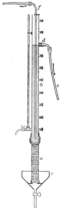
Figure 22. Method of Welitschowsky.
In conducting the experiment, after the apparatus has been arranged as described, the small lateral tubes are, with one exception, closed with stoppers. On the open one, d, a rubber tube is fixed for the purpose of removing the water. The required water pressure is secured by taking the lateral opening corresponding to the pressure required. Water is introduced into the apparatus slowly through the glass tube f.
The water rises to d and then any excess flows off through e. By a proper regulation of the water supply the pressure is kept constant at d. The water flowing off through a is collected by the funnel and delivered to graduated flasks where its quantity can be measured for any given unit of time. Since the rate of flow at first shows variations, the measurement should not be commenced until after the flow becomes constant.
In general, the experiments should last ten hours, and, beginning with a water pressure of 100 centimeters, be repeated successively with pressures of eighty, sixty, forty, and twenty, centimeters, etc. In coarse soils, or with sand, one hour is long enough for the experiment.
176. Statement Of Results.—In the following tables the results for ninety centimeters, seventy centimeters, etc., are calculated from the analytical data obtained for 100 centimeters, eighty centimeters, etc.
158
Material—Quartz Sand.
Liters of Water Passing in Ten Hours.
No. of Exp. Diameter of sand particles in Water pressure in Thickness of Soil Layer.
mm. cm. 10 cm. 20 cm. 30 cm.
1. 0.01–0.71 10 0.244 0.187 0.151
20 0.282 0.198 0.154
30 0.320 0.209 0.158
40 0.358 0.220 0.161
50 0.396 0.231 0.165
60 0.434 0.242 0.168
70 0.472 0.253 0.172
80 0.510 0.264 0.175
90 0.548 0.275 0.179
100 0.586 0.286 0.182
2. 0.071–0.114 10 2.194 1.724 1.425
20 2.898 2.012 1.578
30 3.602 2.300 1.731
40 4.306 2.588 1.884
50 5.010 2.876 2.037
60 5.714 3.164 2.190
70 6.418 3.452 2.343
80 7.122 3.740 2.496
90 7.826 4.028 2.649
100 8.530 4.316 2.802
Similar sets of data have been collected with powdered limestone, clay and humus.
The general conclusions from the experiments are as follows:
1. Clay (kaolin) and humus (peat) are almost impermeable for water, and fine quartz and limestone dust are also very impermeable.
2. The permeability of a soil for water increases as the particles of the soil increase in size, and when particles of different sizes are mixed together the permeability approaches that of the finer particles.
3. The quantity of water passing through a given thickness of soil increases with the water pressure but is not proportional thereto, increasing less rapidly than the pressure.
4. The quantity of water passing under a given pressure is inversely proportional to the thickness of the soil layer when the particles are very fine and the pressure high.
177. Method of Whitney.—To determine the permeability 159of the soil or subsoil to water or air, in its natural position in the field, the following method, due to Whitney, can be recommended:
A hole should be dug, and the soil and subsoil on one side removed to the depth at which the observation is to be made. A column of the soil or subsoil, two inches or more square, and four or five inches deep, is then to be carved out with a broad bladed knife, or a small saw can be conveniently used for cutting this out. A glass or metal frame, a little larger than the sample and three or four inches deep, is slipped over the column of soil, and melted paraffin is run in slowly to fill up the space between the soil and the frame. The soil is then struck off even with the top and bottom of the frame, preferably with a saw, or at any rate taking care not to smooth it over with a knife, which would disturb the surface and affect the rate of flow. The frame is then placed upon some coarse sand or gravel, contained in a funnel, to prevent the soil from falling out and to provide good drainage for the water to pass through. Another similar frame can then be placed on top and secured by a wide rubber band. A little coarse sand, which has been thoroughly washed and dried, is then placed on the soil, and water carefully poured on until it is level with the top of the frame. When the water begins to drop from the funnel more water must be added to the top, so as to have the initial depth of water over the soil the same in all the experiments. A graduated glass is then pushed under the funnel, and the time noted which is required for a quantity of water to pass through the soil. The quantity usually taken for measurement is equivalent to one inch in depth over the soil surface. In taking the sample, root and worm-holes are to be avoided, and these are particularly troublesome in clay lands.
178. Measurement of Percolation through the Soil in Situ.—If lateral translocation could be prevented, the measurement of the quantity of water descending in the soil through a given area would be a matter of simplicity. But to secure accurate results all lateral communication of a given body of soil with adjacent portions must be cut off. Various devices have been adopted to secure this result. An elaborate system 160of lysimetric measurements is illustrated by the apparatus erected by the Agricultural Experiment Station, of Indiana.
The plan and section of the apparatus are shown in Fig. 23.
Each lysimeter box, when finished, resembles somewhat a hogshead with one head out. The sides, however, are perfectly straight inside, having a slight thickening in the center, on the outside, for making them stronger. The sides and bottom of the apparatus are constructed of oak and lined with sheet copper carefully soldered so as to be water-tight. Six inches above, and parallel to the bottom of each of the boxes, is a perforated copper tube, which extends entirely across the lysimeter, and passing through one of the sides connects the box with an underground vault in which the observations are taken. These tubes give an outlet to the drainage water, as described further on. The lysimeters are made of any required depth, the two which are shown in section being three and two-thirds and six and two-thirds feet deep, respectively.
The following method is employed for filling them with soil: There are first placed in the bottom of each lysimeter six inches of fine sand, sifted and washed, which fills them up to the level of the drainage tubes. The lysimeters are then filled with fine, sifted surface soil, to the depth of three and six feet, respectively, making a complete pair of lysimeters, and leaving two inches of the lysimeter boxes projecting above the surface of the soil so that each one will receive exactly its proper share of the rain-fall.
The lysimeters of the other pair, which are the same size as the first, are filled in a different way. The lysimeters are first constructed and placed over vertical columns of soil in situ, which are obtained by digging away all the surrounding soil and leaving the columns standing. The shorter lysimeter is sunk in this way to within two inches of its entire length. It is then tipped over carrying the column of soil with it. Six inches of the subsoil are then removed, when the drainage tube and sand are put in, as in the first pair, and the bottom of the tube soldered in place. The lysimeter is thus filled with the natural soil in place. The longer box is in the same way filled, as far as possible, with the soil in place, but a gravelly nature of the soil may render it impossible to do the filling with a single column unbroken, so the gravel and sand from the lower portion of the soil are to be filled in separately. The drainage tube and bottom of sand are placed in the longer lysimeter in the same way as in the shorter.
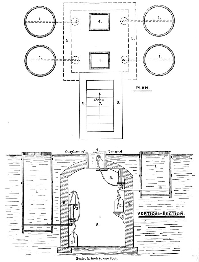
Figure 23. Ground Plan and Vertical Section of Lysimeters and Vaults Showing Position of the Apparatus. 1, 1, 1, 1, Lysimeters. 2, 2, 2, 2, Receiving bottles. 3, 3, Supplying apparatus. 4, 4, Skylights. 5, 5, 5, 5, Wall of vault. 6, 6, Brick walls. 7, Entrance Steps. 8, Vault.
161The purpose of placing sand at the bottom of each lysimeter is to offer a porous stratum in which free water may collect and rise to the level of the perforated copper tube, which would prevent any further rise by conveying the surplus above into the vault as drainage water. The soil above the tube will therefore be constantly drained and the sand below constantly saturated, unless the water be drawn up by the capillary action of the soil as the result of evaporation from the surface.
By means of a proper arrangement within the vault, of a kind of Mariotte’s bottle, the water may be caused to flow back through the drainage tube into the lysimeter to take the place of that lost by evaporation, and thus maintain the level of free water just below the drainage tube. The water flowing back to the lysimeter, and the amount of drainage water, are carefully measured by a system of graduated tubes.
The lysimeters thus constructed represent tile-drained land; in one case the tile being three feet below the surface and in the other six feet below. The drainage waters collected in the receiving bottles can be measured and analyzed from time to time, as occasion may require, to determine the amount of plant food which is removed.
179. Improved Method of Deherain.[120]—Deherain’s earlier experiments were made in pots containing about sixty kilos of soil. These vases serve very well for some kinds of plants, but there are other kinds which do not grow at all normally when their roots are imprisoned. For instance, in pots, even of the largest size, wheat is always poor, beets irregular, maize never acquires its full development, and the conclusions which can be drawn from the experiments can not be predicated of the action of the plant under conditions entirely normal.
It is necessary therefore to carry on the work in an entirely different way, and to construct boxes so large as to make the conditions of growth entirely normal. The arrangement of these boxes is shown in Fig. 24.
162They are placed in a large trench, two meters wide, one meter deep, and forty meters long. There are twenty boxes in this trench, the upper surface of each containing four square meters area. The boxes are one meter deep, and therefore can contain four cubic meters of soil. The sides and bottoms of the boxes are made of iron lattice work, covered with a cement which renders them impervious to water.
The bottom inclines from the sides towards the middle, and from the back to the front, thus forming a gutter which permits of the easy collection of the drainage. The drainage water is conveyed, by means of a pipe and a funnel, into a demijohn placed in the ditch in front of the apparatus, as shown in the figure. These receptacles stand in niches under the front of the cases, and are separated by the brick foundations. Access to them is gained by means of the inclined plane shown in the figure, and this plane permits the demijohns in which the drainage water is collected, to be removed with a wheelbarrow for the purpose of weighing. This apparatus is especially suitable for a study of the distribution of the nitrogen to the crop, the soil and the drainage waters. The loss in drainage waters of potash and phosphoric acid is insignificant in comparison with the loss in nitrogen.
The cases having been placed in position they are filled with the natural soil, which is taken to the depth of one meter, in such a way that the relative positions of the soil and subsoil are not changed.
While the soil is transferring to the cases it is carefully sampled in order to have a portion representing accurately the composition of both the soil and subsoil. These samples are subjected to analysis and the quantities of nitrogen, phosphoric acid, and potash contained therein carefully noted.
One or two cases should be left without crop or fertilizer to determine the relations of the soil and subsoil to the rain-fall. Three or four cases should be kept free of vegetation and receive treatment with different fertilizer, in order to determine the influences of these on the deportment of the soil to rain-fall. The rest of the cases should be seeded with plants representing the predominant field culture of the locality, and some of them should be fertilized with the usual manures used in farm culture.
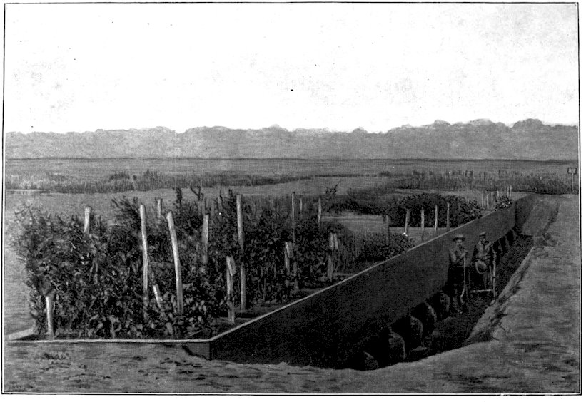
Figure 24. Deherain’s Apparatus for Collecting Drainage Water.
163
AUTHORITIES CITED IN PART THIRD.
165