Part 1 — CHAPTER III.
Reading edition
Applied Optics:—Eye-pieces; Achromatic Objectives; Condensers.
It is almost unnecessary to say that the eye-piece forms a most important part of applied optics in the microscope. It is an optical combination designed to bring the pencil of rays from the objective to assist in the formation of a real or virtual image before it arrives at the eye of the observer. Greater attention has been given of late years to the improvement of the eye-piece, since flatness of field much depends upon it. Opticians have therefore sought to make it both achromatic and compensatory.
There are several forms of eye-pieces in use, some of which partake of a special character, and these will receive attention in their proper places. It is, however, customary among English opticians to denote the value of their several eye-pieces by Roman capitals, A, B, C, D, and E. Continental opticians, on the other hand, have a preference for numerals, 1, 2, 3, 4, 5 and 6, or more, and by which they are recognised.
The eye-piece in more general use is that known as the Huyghenian (Fig. 99); this came into use upwards of two centuries ago. It was constructed by Christian Huyghens, a Dutch philosopher and eminent man of science, secretary to William III.
It was made for the eye-piece of a telescope he constructed with his own hands, and it has been in constant use as the eye-piece of the microscope for nearly two centuries. It consists of two plano-convex lenses, with their plane surfaces turned towards the eye, and divided at a distance equal to half the sum of their focal lengths—in other words, at half the sum of the focal length of the eye-glass and of the distance from the field-glass at which an image from the object glass would be formed, a stop, or diaphragm, being placed between the two lenses for the reason about to be explained. Huyghens himself appears to have been quite unaware of the value of an eye-piece so cleverly constructed.
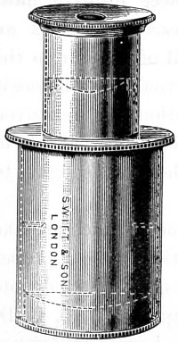
Fig. 99.—Huyghenian Eye-piece A, the dotted lines show position of lenses.
It was reserved for Boscovich to point out that, by this important arrangement, he had corrected a portion of the chromatic aberration incidental to the earlier form of eye-pieces. Let Fig. 100 represent the Huyghenian eye-piece of a microscope, f f being the field-glass, and e e the eye-glass, and l m n the two extreme rays of each of the three pencils emanating from the centre and ends of the object, of which, but for the field-glass, a series of coloured images would be formed from r r to b b; those near r r being red, those near b b blue, and the intermediate ones green, yellow, and so on, corresponding with the colours of the prismatic Spectrum.
The effect described, that of projecting the blue image beyond the red, over-correcting the object-glass as to colour, is purposely produced; it is also seen that the images b b and r r are curved in the wrong direction to be seen distinctly by the convex eye-lens; this then is a further defect of the compound microscope made up of two lenses. But the field-glass, at the same time that it bends the rays and converges them to foci at b′ b′ and r′ r′, also reverses the curvature of the images as here shown, giving them the form best adapted for distinct vision by the eye-glass e e. The field-glass has at the same time brought the blue and red images closer together, so that they produce an almost colourless image to the eye. The chromatic aberration of lenses has been clearly explained in a previous chapter. But let it be supposed that the object-glass had not been over-corrected, that it had been perfectly achromatic; the rays would then have appeared coloured as soon as they had passed the field-glass; the blue rays of the central pencil, for example, would converge at b′′, and the red rays at r′′, which is just the reverse of what is required of the eye-lens; for as its blue focus is also shorter than its red, it would require that the blue image should be at r′′, and the red at b′′. This effect is due to over-correction of the object-glass, which removes the blue foci b b as much beyond the red foci r r as the sum of the distances between the red and the blue foci of the field-lens and eye-lens; so that the separation b r is exactly taken up in passing through those two lenses, and the several colours coincide, so far as focal distance is concerned, as the rays pass the eye-lens. So that while they coincide as to distance, they differ in another respect—the blue image is rendered smaller than the red by the greater refractive power of the field-glass upon the former. In tracing the pencil l, for instance, it will be noticed that, after passing the field-glass, two sets of lines are drawn, one whole and one dotted, the former representing the red, and the latter the blue rays. This accidental effect in the Huyghenian eye-piece was pointed out by Boscovich. The separation into colours of the field-glass is like the over-correction of the object-glass—and opens the way to its complete correction. If the differently-coloured rays were kept together till they reached the eye-glass, they would still be coloured, and present coloured images to the eye. The separating effected by the field-glass causes the blue rays to fall so much nearer the centre of the eye-glass, where, owing to its spherical figure, the refractive power is less than at the margin, so that spherical error of the eye-lens may be said to constitute a nearly equal balance to the chromatic dispersion of the field-lens, and the blue and red rays l′ and l′′ emerge nearly parallel, presenting a fairly good definition of a single point to the eye. The same may be said of the intermediate colours of the other pencils. The eye-glass thus constructed not only brings together the images b′ b′, r′ r′, but it likewise has the most important effect of rendering them flatter, and assisting in the correction of chromatic and spherical aberration.
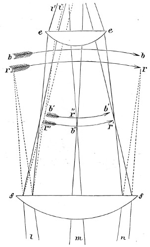
Fig. 100.—Huyghenian Eye-piece.
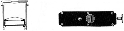
Fig. 101.—Ramsden’s Eye-piece.
The later form of the Huyghenian eye-piece is that of the late Sir George Airy, the field-glass of which is a meniscus with the convex side turned towards the objective, and the eye-lens a crossed convex with its flatter side towards the eye. Another negative eye-piece is that known as the Kellner, or orthoscopic eye-piece. It consists of a bi-convex field-glass and an achromatic doublet eye-lens. This magnifies ten times, but it in no way compares with the Huyghenian in value. Neither does it afford the same flatness of field.
The Ramsden, or positive eye-piece, is chiefly employed as a micrometer eye-piece for the measurement of the values of magnified images. The construction of this eye-piece is shown in Fig. 101, a divided scale being cut on a strip of glass in 1⁄100ths of an inch, every fifth of which is cut longer than the rest to facilitate the reading of the markings, and at the same time that of the image of the object, both being distinctly seen together, as in the accompanying reduced micro-photograph of blood corpuscles, Fig. 102.
The value of such measurements in reference to the real object, when once obtained; is constant for the same objective. It becomes apparent, then, that the value of the divisions seen in the eye-piece micrometer must be found with all the objectives used, and carefully tabulated.
It was Mr. Lister who first proposed to place on the stage of the microscope a divided scale of a certain value. Viewing the scale as a microscopic object, he observed how many of the divisions on the scale attached to the eye-piece corresponded with one or more of a magnified image. If, for instance, ten of those in the eye-piece correspond with one of those in the image, and if the divisions are known to be equal, then the image is ten times larger than the object, and the dimensions of the object ten times less than that indicated by the micrometer. If the divisions on the micrometer and on the magnified scale are not equal, it becomes a mere rule-of-three sum; but in general this trouble is taken by the maker of the instrument, who furnishes a table showing the value of each division of the micrometer for every object-glass with which it will be employed.
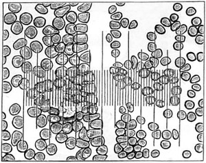
Fig. 102.—Blood Corpuscles and Micrometer, magnified 1·3500.
Mr. Jackson’s simple and cheap micrometer is represented in Fig. 103. It consists of a slip of glass placed in the focus of the eye-glass, with the divisions sufficiently fine to have the value of the ten-thousandth part of an inch with the quarter-inch object-glass, and the twenty-thousandth with the eighth; at the same time the half, or even the quarter of a division may be estimated, thus affording the means of attaining considerable accuracy, and may be used to supersede the more complicated and expensive screw-micrometer, being handier to use, and not liable to derangement in inexperienced hands.
The positive eye-piece affords the best view of the micrometer, the negative of the object. The former is quite free from distortion, even to the edges of the field; but the object is slightly coloured. The latter is free from colour, and is slightly distorted at the edges. In the centre of the field, however, to the extent of half its diameter, there is no perceptible distortion, and the clearness of the definition gives a precision to the measurement which is very satisfactory.
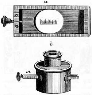
Fig. 103.—Jackson’s Eye-piece Micrometer.
Short bold lines are ruled on a piece of glass, a, Fig. 103, to facilitate counting, the fifth is drawn longer, and the tenth still longer, as in the common rule. Very fine levigated plumbago is rubbed into the lines to render them visible; they are then covered with a piece of thin glass, cemented by Canada balsam, to prevent the plumbago from being wiped out. The slip of glass thus prepared is secured in a thin brass frame, so that it may slide freely into its place.
Slips are cut in the negative eye-piece on each side, so that the brass frame may be pressed across the field in the focus of the eye-glass, as at m; the cell of which should have a longer screw than usual, to admit of adjustment for different eyes. The brass frame is retained in its place by a spring within the tube of the eye-piece; and in using it the object is brought to the centre of the field by the stage movements; the coincidence between one side of it and one of the long lines is made with great accuracy by means of the small screw acting upon the slip of glass. The divisions are then read off as easily as the inches and tenths on a common rule. The operation, indeed, is nothing more than the laying of a rule across the body to be measured; and it matters not whether the object be transparent or opaque, mounted or unmounted, if its edges can be distinctly seen, its diameter can be taken.
Previously, however, to using the micrometer, the value of its divisions should be ascertained with each object-glass; the method of doing this is as follows:—
Place a slip of ruled glass on the stage; and having turned the eye-piece so that the lines on the two glasses are parallel, read off the number of divisions in the eye-piece which cover one on the stage. Repeat this process with different portions of the stage-micrometer, and if there be a difference, take the mean. Suppose the hundredth of an inch on the stage requires eighteen divisions in the eye-piece to cover it; it is plain that an inch would require eighteen hundred, and an object which occupied nine of these divisions would measure the two-hundredth of an inch. Take the instance supposed, and let the microscope be furnished with a draw-tube, marked on the side with inches and tenths. By drawing this out a short distance, the image of the stage micrometer will be expanded until one division is covered by twenty in the eye-piece. These will then have the value of two-thousandths of an inch, and the object which before measured nine will then measure ten; which, divided by 2,000, gives the decimal fraction ·005.
Enter in a table the length to which the tube is drawn out, and the number of divisions on the eye-piece micrometer equivalent to an inch on the stage; and any measurements afterwards taken with the same micrometer and object-glass may, by a short process of mental arithmetic, be reduced to the decimal parts of an inch, if not actually observed in them.
In ascertaining the value of the micrometer with a deep objective, if the hundredth of an inch on the stage occupies too much of the field, then the two-hundredth or five-hundredth should be used and the number of the divisions corresponding to that quantity be multiplied by two hundred or five hundred, as the case may be.
The micrometer should not be fitted into too deep an eye-piece, as it is essential to preserve good definition. A middle-power Kellner or Huyghenian is frequently employed; at all events, use the eye-piece of lower power rather than impair the image.
The eye-lens above the micrometer should not be of shorter focus than three-quarters of an inch, even with high-power objectives.
The Ramsden Eye-piece.—The cobweb micrometer is the most efficient piece of apparatus yet brought into use for measuring the magnified image. It is made by stretching across the field of the eye-piece two extremely fine parallel wires or cobwebs, one or both of which can be separated by the action of a micrometer screw, the trap head of which is divided into a hundred or more equal parts, which successively pass by an index as the milled head is turned, shown in Fig. 104. A portion of the field of view is cut off at right angles to the filaments by a scale formed of a thin plate of brass having notches at its edges, the distances between which correspond to the threads of the screw, every fifth notch (as in the previous case) being made deeper than the rest, to make the work of enumeration easier. The number of entire divisions on the scale shows then how many complete turns of the screw have been made in the separation of the wires, while the number of index points on the milled head shows the value to the fraction of a turn, that may have been made in addition. A screw with one hundred threads to the inch is that usually employed; this gives to each division in the scale in the eye-piece the value of 1⁄100th of an inch. The edge of the milled head is also divided into the same number of parts.
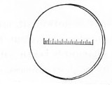
Micrometer scale to drop into Eye-piece.
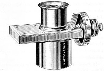
Fig. 104.—Ramsden Screw Micrometer Eye-piece.
In Watson’s Ramsden screw micrometer, Fig. 104, the micrometer scale (seen detached) is ruled on a circular piece of glass, and this, by unscrewing the top, is dropped into its place, and one of the wires, both being fixed, is set a little to the side of the field, the teeth of the screw being cut to 1⁄100ths, and the drum giving the fractional space between the teeth to 1⁄100ths, so that the 1⁄10000th of an inch can be read off. This micrometer eye-piece is constructed entirely of aluminium, a decided advantage, being so much lighter than brass to handle.
In the screw micrometer of other makers, other modifications are found. An iris diaphragm being placed below the web to suit the power of the eye-piece employed, a guiding line at right angles to the web is sometimes added. Care should be taken to see that when the movable web coincides exactly with the fixed web, the indicator on the graduated head stands at zero.
The Compensating Eye-piece.—The very important improvements effected in the construction of the objective naturally led up to an equally useful change for the better in the eye-piece.
All objectives of wide aperture, from the curvature of their hemispherical front lenses, show a certain amount of colour defect in the extra-axial portion of the field, even if perfectly achromatic in the centre. Whether an image be directly projected by the objective, or whether it be examined with an aplanatic eye-piece, colour fringes may be detected, possibly in an increasing degree towards the periphery. This residual chromatic aberration has at length been very nearly eliminated by the aid of the compensating eye-piece.
The construction of compensating eye-pieces is somewhat remarkable, since they have an equivalent error in an opposite direction—that is, the image formed by the red rays is greater than that corresponding to the blue rays; consequently, eye-pieces so constructed serve to compensate for the unequal magnification produced by different coloured rays, and images appear free from colour up to the margin of the field.
Zeiss’s compensating eye-pieces are so arranged that the lower focal points of each series lie in the same plane when inserted in the body-tube of the microscope; no alteration of focus is therefore required on changing one eye-piece for another. This of itself is not only an advantage but also a saving of time, while the distance between the upper focal point of the objective and the lower one of the eye-piece, which is the determining element of magnification, remains constant.
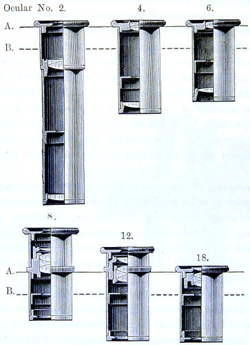
Fig. 105.—A sectional view of Zeiss’s Compensating series of Eye-pieces, ½ the full size.
A.—Plane of the upper edge of the tube.
B.—Lower focal plane of eye-pieces, with their lenses in situ.
The ordinary working eye-pieces, Huyghenian and others, commencing with a magnification of four diameters, are so constructed that they can be conveniently used, as we are accustomed to use them in England, with high powers, Zeiss’s Nos. 12 and 18 compensating eye-pieces being adapted for use with his lower power apochromatic lenses of 16 and 8 mm. The numbering of the eye-pieces is carried out on the plan originally proposed by Professor Abbe—that is, the number denotes how many times an eye-piece, when employed with a given tube-length, increases the initial magnifying power of the objective, and at the same time furnishes figures for their rational enumeration. It is on this basis that the German compensating eye-pieces have been arranged in series, and in agreement with their magnifying power and distinctive numberings of 2, 4, 6, 8, 12, 18. Of these several eye-pieces, 12 is found to be the most useful. The magnification obtained by combining a compensating eye-piece with any apochromatic objective is found by multiplying its number by the initial magnification of the objective, as given in the following proof:—An objective of 3·0 mm. focus, for example, gives in itself a magnification of 83·3 (calculated, for the conventional distance of vision, 250 mm.); eye-piece 12 therefore gives with this objective a magnification of 12 × 83·3 = 1000 diameters. The classification, however, of these eye-pieces, as furnished by Abbe, is dependent upon increase in the total magnifying power of the microscope obtained by means of the eye-piece as compared with that given by the objective alone. The numbering, then, denotes how many times an eye-piece increases the magnifying power of the objective when used with a given body-tube; the proper measure of the eye-piece magnification; and, at the same time, the figures for rational enumeration.
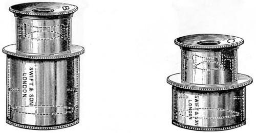
Fig. 106.—B and C Achromatic Eye-pieces.
Compensating eye-pieces have been introduced for the correction of certain errors in high-power objectives—those made with hemispherical fronts. All such lenses, whether apochromatic or not, are greatly improved by the compensating eye-piece, but the dry objective and the lower powers are certainly deteriorated. The lower power compensating eye-pieces are Huyghenian, the higher are combinations, with no field-lens, and therefore in working act as a single or positive eye-piece. This is of importance to those who work with low powers—the older forms of objectives.
Messrs. Watson and Swift have adopted a new formula for their series of achromatic eye-pieces, whereby their magnification and flatness of field are improved. These also bear a constant ratio to the initial power of their objectives.
The compensating eye-pieces of these makers are constructed on the same principle as those of Zeiss’s for the correction of errors of colour in the marginal portion of the field, and consequently are in every way as effective as those of Continental manufacture. Figs. 106, 107, and 108 show in dotted outline the form and position of the several lenses combined in these eye-pieces.
Projection Eye-pieces are chiefly used in micro-photography, and for screen demonstrations. The cap of this eye-piece is provided with a spiral adjustment for focussing, the diaphragm being placed in front of the eye-lens, an essential arrangement for obtaining an accurate focus. The ring seen below the cap, Fig. 108, is graduated so that the rotation for distance of screen may be carefully recorded.
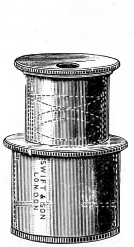
Fig. 107.—The Compensating Eye-piece.
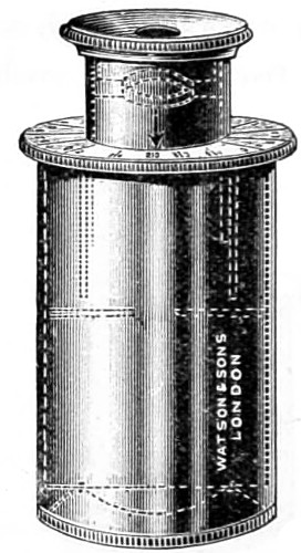
Fig. 108.—Projection Eye-piece.
Schmidt’s goniometer positive eye-piece, for measuring the angles of crystals, is so arranged as to be easily rotated within a large and accurately graduated circle. In the focus of the eye-piece a single cobweb is drawn across, and to the upper part is attached a vernier. The crystals being placed in the field of the microscope, care being taken that they lie perfectly flat, the vernier is brought to zero, and then the whole apparatus turned until the line is parallel with one face of the crystal; the frame-work bearing the cobweb, with the vernier, is now rotated until the cobweb becomes parallel with the next face of the crystal, and the number of degrees which it has traversed may then be accurately read off.
Goniometer.—If a higher degree of precision is required, then, the double-refracting goniometer invented by the late Dr. Leeson must be substituted. With this goniometer (Fig. 109) the angles of crystals, whether microscopic or otherwise, can be measured. It has removed the earlier difficulties incident to similar instruments formerly in use. Among other advantages, it is capable of measuring opaque and even imperfect crystals, beside microscopic crystals and those in the interior of other transparent media. It is equally applicable to the largest crystals, and will measure angles without removing the crystal from a specimen, provided only the whole is placed on a suitable adjusting stage. The value of the goniometer depends on the application of a doubly refracting prism, either of Iceland spar or of quartz, cut of such a thickness as will partially separate the two images of the angle it is proposed to measure.
Dr. Leeson strongly insisted on the importance of the microscope in the examination of the planes of crystals subjected to measurement, as obliquity in many cases arises from not only conchoidal fractures, but also from imperfect laminæ elevating one portion of a plane, and yet allowing a very tolerable reflection when measured by the double refracting goniometer.
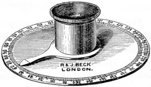
Fig. 109.—Leeson’s Goniometer.
Microscopes for crystallographic and petrological research are now specially constructed for measuring the angles of crystals.
Erector eye-pieces and erecting prisms are employed for the purpose of causing the image presented to the eye to correspond with that of the object. They are also helpful in making minute dissections of structure; the loss of light, however, by sending it through two additional surfaces is a drawback, and impairs the sharpness of the image. Nachet designed an extremely ingenious arrangement whereby the inverted image became erect; he adapted a simple rectangular prism to the eye-piece. The obliquity which a prism gives to the visual rays when the microscope is used in the erect position, as for dissecting, is an advantage, as it brings the image to the eye at an angle very nearly corresponding to that of the inclined position in which the microscope is ordinarily used.
The Achromatic Objective.
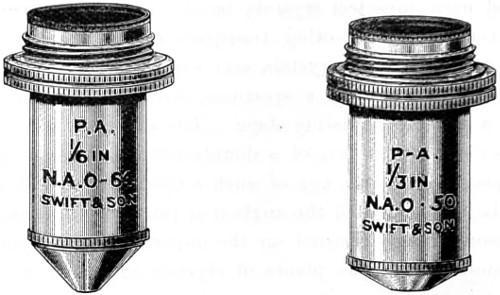
Fig. 110.—Pan-aplanatic Achromatic Objectives.
The Achromatic Objective, of all the optical and mechanical adjuncts to the microscope, is in every way the most necessary, as well as the most important. The ideal of perfection aimed at by the optician is a combination of lenses that shall produce a perfect image—that is, one absolutely perfect in definition and almost free from colour. The method resorted to for the elimination of spherical and chromatic aberration in the lens has been fully explained in a former chapter. It will now be my endeavour to show the progressive stages of achromatism and evolution of the microscope throughout the present century.
It is almost as difficult to assign the date of the earliest application of achromatism to the microscope as to that of the inception and many modifications of the instrument in past ages; indeed, the question of priority in every step taken in its improvement has been the subject of controversy.
Among the earlier workers in the first decade of this century will be found the name of Bernardo Marzoni, who was curator of the Physical Laboratory of the Lyceum of Brescia. He, an amateur optician, it has come to light, in 1808 constructed an achromatic objective, and exhibited it at Milan in 1811, when he obtained the award of a silver medal for its merits, under the authority of the “Institute Reale delli Scienzo.” Through the good offices of the late Mr. John Mayall one of Marzoni’s objectives, which had been carefully preserved, was presented to the Royal Microscopical Society of London in 1890.20 This objective is a cemented combination, with the plane side of the flint-lens presented to the object. This was an improvement of a practical kind, and of which Chevalier subsequently availed himself. In 1823 Selligue, a French optician, is credited with having first suggested the plan of combining two, three, or four plano-convex achromatic doublets of similar foci, one above the other, to increase the power and the aperture of the microscope. Fresnel, who reported upon this invention, preferred on the whole Adam’s arrangement, because it gave a larger field. Selligue subsequently improved his objective by placing a small diaphragm between the mirror and the object.
In this country, Tully was induced by Dr. Goring to work at the achromatic objective, and his first efforts were attended with a success quite equal to that of Chevalier’s. Lister on examining these lenses said:—“The French optician knows nothing of the value of aperture, but he has shown us that fine performance is not confined to triple objectives.” Amici, the amateur optician of Modena, visited this country in 1827 and brought his achromatic microscope and objectives, which were seen to give increase of aperture by combining doublets with triplets. The most lasting improvement in the achromatic objective was that of Joseph Jackson Lister, F.R.S., the father of Lord Lister, and one of the founders of the Royal Microscopical Society of London.
Lister’s discoveries at this period (1829) in the history of the optics of the microscope were of greater importance than they have been represented to be. That he was an enthusiast is manifest, for, being unable to find an optician to carry out his formula for grinding lenses, he at once set to work to grind his own, and in a short time was able to make a lens which was said to be the best of the day.
Lister, in a paper contributed to the proceedings of the Royal Society the same year, pointed out how the aberrations of one doublet could be neutralised by a second. He further demonstrated that the flint lens should be a plano-concave joined by a permanent cement to the convex crown-glass. The first condition, he states, “obviates the risk of error in centring the two curves, and the second diminishes by one half the loss of light from reflection, which is very great at the numerous surfaces of every combination.” These two conditions then—that the flint lens shall be plano-concave, and that it shall be joined by some cement (Canada balsam) to the convex—may be taken as the basis for the microscopic objective, provided they can be reconciled with the correction of spherical and chromatic aberration of a large pencil.
Andrew Ross was not slow to perceive the value of Lister’s suggestions and in 1831 he had constructed an object-glass on the lines laid down by Lister, Fig. 112; a a′ representing the anterior pair, m the middle, and p the posterior, the three sets combined forming the achromatic objective, consisting of three pairs of lenses, a double-convex crown-glass, and a plano-concave of flint.
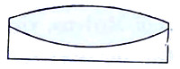
Fig. 111.—Lister’s double-convex crown and plano-concave flint cemented combination.
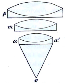
Fig. 112.—Andrew Ross’s ¼-inch Objective.
Lister proposed other combinations, and himself made an object-glass consisting of a meniscus pair with a triple middle, and a back plano-convex doublet. This had a working distance of ·11 and proved to be so great a success that other opticians—Hugh Powell, 1834; James Smith, 1839—made objectives after the same formula.
The publication of Lister’s data proved of value in another direction: it stimulated opticians to apply themselves to the further improvement of the achromatic objective. Andrew Ross was one of the more earnest workers in giving effect to Lister’s principles and a short time afterwards found that a triple combination, with the lenses separated by short intervals, gave better results. In the accompanying diagram the changes made in the combination of the objective from 1831, and extending over a period of about twenty years from this date, are shown.
Each objective, from the ½-inch to the 1⁄12-inch, is seen to be built up of at least six or eight different fronts, the back combinations being a triplet formed of two double-convex lenses of crown glass with an intermediary double concave lens of flint-glass.
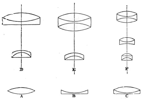
Fig. 113.—Combinations of Early Dry Objectives.
A, Double-convex lens; B, Plano-concave; C, Bi-convex and plano-concave united; shown in their various combinations, as at D, form the 3-in., 2-in. or 1½-in.; at E, 1-in. and 2⁄3-in.; and at F, the ½-in., 4⁄10-in., ¼-in. and 1⁄25-in. objectives.
Combination D was for many years known as the Norfolk Objective.
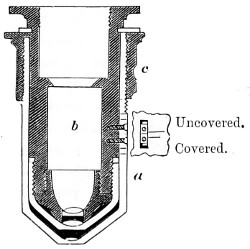
Fig. 114.—Lister’s CorrectionCollar, (in section).
No sooner had Ross constructed ¼-inch achromatic objectives on Lister’s formula than he discovered an error which had hitherto escaped attention, viz., that the thinnest cover-glass of an object produced a considerable amount of refractive disturbance. A marked difference was observed in the image when viewed with or without a cover-glass. This difficulty was first met by the addition of a draw-tube to the microscope body. But as this also impaired the image, Lister overcame the difficulty by mounting the front lens of the objective in a separate tube made to fit over a second tube carrying the two pairs of lenses. This arrangement led up to his invention of the screw-collar adjustment, the mechanism for applying which is shown in Fig. 114. The anterior lens a at the end of the tube is enclosed in a brass-piece b containing the combination; the tube a, holding the lens nearest the object, is then made to move up or down the cylinder b, thus varying the distance, according to the thickness of the glass covering the object, by turning the screw ring c, thus causing the one tube to slide over the other, and clamping them together when properly adjusted. An aperture is made in the tube a, within which is seen a mark engraved on the cylinder, on the edge of which are two marks, a longer and a shorter, engraved upon the tube. When the mark on the cylinder coincides with the longer mark on the tube, the adjustment is made for an uncovered object; and when the coincidence is with the shorter mark, the proper distance is obtained to balance the aberrations produced by a cover-glass the hundredth of an inch thick; such glass covers are now supplied. The adjustment should be tested experimentally by moving the milled edge which separates or closes the combinations, and at the same time using the fine adjusting screw of the microscope. The difficulty associated with the cover-glass of old has, by the introduction of the homogeneous immersion system, been very nearly eliminated. There still remains, however, a disturbing amount of residual colour aberration in the achromatic dry objective, and for the correction of which Zeiss proposed mounting the several lenses on a method somewhat different to that so long in use in this country. Fig. 115 shows an objective in which the screw-collar ring b b is made to adjust the exact distance between the two back lenses placed at a a. The value of the screw-collar is not questioned. It is difficult to obtain at all times cover-glasses of a perfectly uniform thickness; they will vary, and therefore perfect definition must be obtained, as heretofore, by adjusting for each separate preparation while the object is under examination.
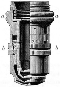
Fig. 115.—The Continental Screw-collar Adjustment.
As early as 1842 the excellence of Andrew Ross’s achromatic objectives were acknowledged, and his formula for their construction was generally followed. No doubt many of these early objectives of his manufacture are still regarded as treasures. I possess a ½-inch and a ¼-inch, which I believe to be comparable with any achromatic objectives of the same apertures of the present day. These I have always found most serviceable for histological work.
In 1850 Mr. Wenham produced an achromatic objective of considerable achromatic value. This consisted of a single hemispherical front combination, shown in the accompanying enlarged diagram, Fig. 116. Wenham’s formula seems to have been generally adopted by Continental opticians, who sold these lenses at a reduction of price. In Paris, Prazmowski and Hartnack—I have had one of Hartnack’s earliest immersions in use for many years—brought this form of objective to greater perfection, and in 1867 Powell and Lealand adopted the single front combination system in their early water-immersion objective, whereby the focal distance was said to be “practically a constant quantity, while reduction of aperture by making the front lens thinner ensures a much greater working distance without affecting the aberrations, since the first refraction takes place at the posterior or curved surface of the front lens, the removal of any portion of thickness at the anterior or plane surface simply cuts off zones of peripheral rays without altering the distance—any space being filled by the homogeneous immersion fluid, or by an extra thickness of cover-glass.”21
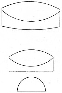
Fig. 116.—A Single Front Combination formulated by Wenham for Messrs. Ross (enlarged).
Great improvements were brought about by R. B. Tolles, of Boston, 1874, in the objective, as well as in the optical and mechanical parts of the microscope, most of which, however, must be ascribed to the criticisms and suggestions of amateur workers skilled in the exhibition of test-objects—the late Dr. Woodward of Washington, for example, whose series of photographs of the more difficult frustules of diatoms have rarely been surpassed. Such results were due to improvements made in the optical part of the microscope at his suggestion. He came to the conclusion, arrived at about the same time by mathematical scientists, that increase of power in the microscope was only possible in two directions, the qualitative and the quantitative.
It was now that microscopists turned to the late Professor Abbe for assistance in perfecting the objective in the dioptric direction. This, he pointed out, must be looked for in further improvements in the art of glass-making.
A series of experiments ultimately brought to light a mineral substance, Fluorite, which, when combined in the proper proportion, one part to two of German crown and flint glass, was found to have the qualities looked for, and to possess different relations of a dispersive and refractive power. From Professor Abbe’s researches, begun in 1876, we have had the aperture of the objective greatly enlarged, and the homogeneous system brought into general use.
Previous to this date the best made objective merely approximated to colour correction. Undoubtedly the chief object to be obtained was the removal or diminution of the secondary colour aberration. This, together with other residual errors Abbe pointed out in 1880, led to the improvement of the optical quality of the glass used in the manufacture of all optical instruments, the chief difficulties being surmounted in the Jena glass factory, whereby a complete revolution was effected in the microscopic objective. The apochromatic glasses of Zeiss, Powell, Beck, Ross, Watson, Swift, and other makers, in which the secondary spectrum has been totally eliminated, or only a negligible tertiary spectrum remains—that is to say, the objectives of these makers—are now corrected for three spectrum rays, and not two, as in the older objectives; and only those who look forward for making further discoveries in the intimate structure of bacilli or for resolving the finest diatom markings can be said to fully appreciate the importance and value of the investigations of the late Professor Abbe, and which have, so to speak, entirely changed old empirical views as to the value of high aperture, and demonstrated that high amplification, unless associated by proportionally high aperture, necessarily produces untrue images of minute structures. It was he also who introduced a practically perfect system of estimating apertures, known as the “numerical aperture notation,” by which not only can an accurate comparison be made of the relative apertures of any series of objectives, whether dry or immersion, but their resolving power under the various conditions of the kind of light employed. Their penetrating power and their illuminating power can now be estimated with mathematical exactness.
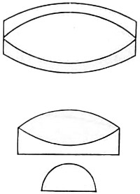
Fig. 117.—Diagram of an Apochromatic Combination.
The practical advantages, then, secured by the adoption of the homogeneous system were, on the whole, greater than any before made or believed to be possible, and when taken into account in connection with the improvement of the eye-piece (also due to Abbe), almost perfect achromatism and homogeneity between objective, object, and eye-piece is secured, together with a sharp definition of the image over the whole visual field. These, with an increase of working distance between the object and the objective, and other important results, have been placed within the reach of the microscopist by men of science, and the outcome is the general adoption of the homogeneous system, termed by Carl Zeiss, a fellow-worker with Abbe, the22 apochromatic system of constructing objectives.
Relative Merits of the English and German Objectives.
As to the relative merits of German-made objectives, no superiority can be claimed for them over those made by English opticians.
The Continental form of the 1⁄12-inch oil-immersion objective, shown in Fig. 118, on the scale of 6 to 1, consists of four systems of lenses, namely, the front, a deep hemispherical crown lens of high refractive index; the second front of the system, an achromatic lens of such a form that it gathers the light from the hemispherical front; the middle lens, a single meniscus; and the back an achromatised lens, the second front of the back being connected in such a way as to compensate for the spherical and chromatic aberrations of the front lens.
The first homogeneous immersion objective which came under my observation was manufactured in the well-known Jena workshop of Carl Zeiss, December, 1877. This had a very considerable increase of numerical aperture, upwards of 50 per cent.; a clear gain, as an oil angle of even 110° proved to be of greater value than an angle of 180° in air, while the resolving power of the objective was increased in like proportion. There does not at present appear to be a bar to the construction of objectives of yet higher power, with increase of aperture. The available course open in this direction is the further discovery of another vitreous material and a suitable immersion fluid with an index of 1·8 or 1·9, and glass with a corresponding index, so as to ensure homogeneity of the combination. Zeiss asserts that in the more difficult departments of microscopical research the apochromatic lenses will supplant the older objectives, yet there are many problems in microscopy awaiting solution which do not demand the highest attainable degree of perfection in the objective, and in the majority of cases the older achromatic objective is all that is needful, provided it is good of its kind. The achromatic objectives and eye-pieces of the older type have still an advantage, as, owing to their simpler construction, really good lenses of the class required can be purchased at considerably lower prices than the objectives of the new series. These, from being more complicated in construction, involve a greater amount of skilled manual labour.
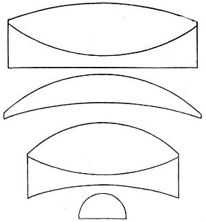
Fig. 118.—The Continental 1⁄12-in. Oil-immersion Combination (enlarged diagram).
The German glasses of to-day afford satisfactory evidence both of skill and workmanship displayed in their production. Their cost is greater, then, for the reason given, as will be seen on reference to Continental catalogues. The dry series of objectives cost somewhat less, a ½-inch (numerical aperture 0·30) can be had for £1 10s., and a 1⁄6-inch (numerical aperture 0·65) for £2. On the other hand, the apochromatic series rapidly increase in price as the numerical aperture approaches the limit of numerical aperture 0·40. The best of Zeiss’s series are the 12 mm. (½-inch) and the 3 mm. (1⁄8-inch), numerical aperture 1·4, both of which possess the optical capacity assigned to them. These objectives are undoubtedly the finest to be met with in the workshop of any optician. Achromatic objectives of Continental manufacture have been as much improved as those of English make by the introduction of the newer varieties of glass, as already explained, while a new nomenclature has sprung up in consequence. We now have semi-apochromatic and parachromatic. The German opticians have followed Zeiss’s lead, since almost the same series of objectives are given in the catalogues of Leitz, Reichert, and Seibert, while the quality of both dry and immersion objectives is found to be much the same. The low price of Reichert’s immersion objectives should be noted, as their performance is quite perfect. A 1⁄12-inch (numerical aperture 1·30) of Leitz’s, with which I have worked at bacteria, has given me much satisfaction; supplied by Watson and Baker at £5. A 1⁄12-inch dry objective by the same maker (numerical aperture 0·87) costs £3, and a water immersion 1⁄12-inch (numerical aperture 1·10) £3 5s. Leitz reminds me that it requires a good lens of from six to seven hundred magnifying power for the examination of bacteria. For this reason he has constructed a new form of lens, a 1⁄10-inch oil-immersion of 2·5 mm. focus, for the purpose of adding to the resources of bacteriology. This lens necessarily has a lower magnification than his former 1⁄12-inch oil-lens, but as it is less costly to manufacture it is sold at a smaller price. The before-mentioned 1⁄12-inch, with a No. 3 compensating eye-piece, gives a magnification of over seven hundred or eight hundred diameters. To secure the best results in using the higher powers of Leitz’s, from No. 5 upwards, a cover-glass of 0·17 mm. in thickness should be used, and care taken to make the length of the draw-tube equal to 170 mm. This length of tube should be adhered to in the use of this optician’s oil-immersion lenses. If the microscope be provided with a nose-piece, the draw-tube should be drawn out to 160 mm.; in its absence it should be set at 170 mm., a deviation of 10 mm. or more from the correct tube-length deteriorates from the value of Leitz’s oil-immersion objectives as of other opticians. It is suggested that the German apochromatic combination of three cemented lenses is that adopted by Steinheil long before, in the construction of his well-known hand-magnifier (see page 77, Fig. 51). Zeiss’s 3 mm. objective has a triple front, balanced by two triple backs—in all nine lenses—a somewhat amplified diagram of which is represented in Fig. 118. The formula for this combination was furnished by Tolles, of Boston, America, and it at once secured increase of aperture (the value of this optician’s many contributions to microscopy has since his death been generally acknowledged). The metrical equivalent focus assigned by Zeiss to his series of dry achromatic objectives is given in somewhat ambiguous terms, which tend to confuse rather than classify them; for instance, two lenses of the same aperture—24 mm. and 16 mm.—corresponding to the English 1-inch and 2⁄3-inch, each have assigned to them an aperture of 0·30; a 12 mm. and 8 mm., corresponding to the English ½-inch and 1⁄3-inch, have an aperture of 0·65; while a 6 mm. = ¼-inch, and a 4 mm. = ¼-inch and 1⁄6-inch, have each an aperture of 0·95.
Nachet exhibited at the Antwerp Exhibition a fine 1⁄10-inch oil-immersion, which was highly praised by the jurors.
It is necessary, to make the fact perfectly clear, that dry and immersion lenses having the same angular aperture have also a similar defining power. The pencil of rays, however, differs in intensity and density as the rays emerging from the cover-glass of the object into air are very considerably deflected, and the cone suffers a corresponding loss of brightness. On this important point, then, I believe it will prove of value to interpolate a clear and full exposition of the change brought about by the cover-glass.
It is not difficult, then, to perceive the importance of Amici’s discovery as to the value of a drop of water inserted between the object and the objective, and it now seems somewhat surprising it should have been so long neglected by opticians, since it is at once seen to diminish the reflection which takes place in the incidence of oblique light. The film of water not only gives increased aperture, but also greater cleanness and sharpness to the image. The film, then, as already shown, collects the straying away of peripheral rays of light, and sends them on to the eye-piece, and greatly assists in rendering the image more perfect, and materially aids in the removal of residuary secondary aberrations; while with air, or dry objectives, a certain amount of aberration takes place, sufficient to affect the pencils on their passage from the radiant to the medium of the front lens, adding a considerable ratio to the total spherical aberration with the objective, which, in the case of wide angles, increases disproportionately from the axis outwards. This can only be corrected by a rough method of balancing; that is, by introducing an excess of opposite aberration in the posterior lens. An uncorrected residuum, rapidly increasing with larger apertures, is then left, and this appears in the image amplified by the total power of the objective, so that with a non-homogeneous medium there is a maximum angular aperture which cannot be surpassed without undergoing a perceptible loss of definition, provided working distance is required. If we abolish the anterior aberration for all colours, by an immersion fluid which is equal to cover-glass in refractive and dispersive power, the difficulty is at once overcome. If, for instance, we have an objective of 140° in glass (= 1·25 N.A.) and water as the immersion fluid, the aberration in front would affect a pencil of 140°. Substituting a homogeneous medium, the same pencil, contracted to the equivalent angle in that medium of 112°, will be admitted to the front lens without any aberration, and may be made to emerge from the curved surface also without any disturbing aberration, but contracted to an angle varying from 70° to 90°. The first considerable spherical aberration of the pencil then occurs at the anterior surface of the second lens, where the maximum obliquity of the rays is already considerably diminished.
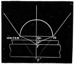
Fig. 119.
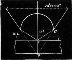
Fig. 119a.
Figs. 119 and 119a will doubtless make this clearer. If the objective of 140° works with water (Fig. 119), there would be a cone of rays extending up to 70° on both sides of the axis, and this large cone would be submitted to spherical aberration at the front surface a. But with homogeneous immersion Fig. 119a) the whole cone of 112° is admitted to the front lens without any aberration, there being no refraction at the plane surface; and as the spherical surface of the front lens is without notable spherical aberration, the incident pencil is brought from the focus F to the conjugate focus F′, and contracted to an angle of divergence of 70°-90° without having undergone any spherical aberration at all.
The problem of correcting a very wide-angled objective has thus been reduced by the homogeneous oil-immersion system, both in theory and practice.23
Abbe’s Test-plate.
Abbe designed the test-plate (Fig. 120) for testing the spherical and chromatic aberrations of objectives, and estimating the thickness of cover-glasses corresponding to the most perfect correction: six glasses, having the exact thickness marked on each, 0·09 to 0·24 mm., cemented in succession on a slip, their lower surface silvered and engraved with parallel lines, the contours of which form the test. These being coarsely ruled are easily resolved by the lowest powers; yet, from the extreme thinness of the silver, they form also a delicate test for objectives of the highest power and widest aperture. The test-plate in its original size is seen in Fig. 120, with one of the circles enlarged.
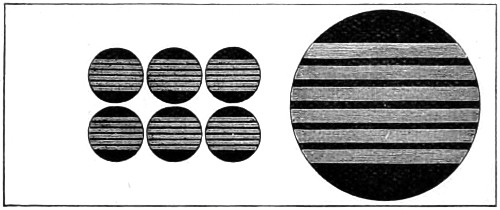
Fig. 120.—Abbe’s Test-plate for estimating thickness of glass-covers.
To examine an objective of large aperture, the discs must be focussed in succession, observing in each case the quality of the image in the centre of the field, and the variation produced by using, alternately, central and very oblique illumination.
When the objective is perfectly corrected for spherical aberration, the outlines of the lines in the centre of the field will be perfectly sharp by oblique illumination, and without any nebulous doubling or indistinctness of the edges. If, after exactly adjusting the objective for oblique light, central illumination is used, no alteration of the focus should be necessary to show the outlines with equal sharpness.
If an objective fulfils these conditions with any one of the discs, it is free from spherical aberration when used with cover-glasses of that thickness. On the other hand, if every disc shows nebulous doubling, or an indistinct appearance of the edges of the line with oblique illumination, or, if the objective requires a different focal adjustment to get equal sharpness with central as with oblique light, the spherical correction of the objective is more or less imperfect.
Nebulous doubling with oblique illumination indicates over-correction of the marginal zone; indistinctness of the edges without marked nebulosity indicates under-correction of the zone; an alteration of the focus for oblique and central illumination points to an absence of concurrent action of the separate zones, which may be due to either an average under or over correction, or to irregularity in the convergence of the rays.
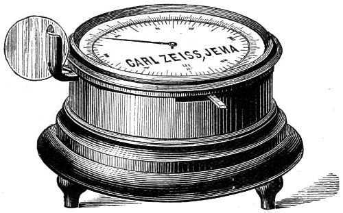
Fig. 121.—Zeiss’s Cover-glass Gauge.
COVER-GLASS GAUGE.
Zeiss has gone a step further to lay the microscopist’s ghost of the cover-glass. He invented a measurer (Fig. 121) whereby the precise determination of thickness of glass-covers can be obtained. This measurement is effected by a clip projecting from a circular box; the reading is given by an indicator moving over a divided circle on the lid of the box. The divisions seen cut round the circumference show 1⁄100ths of a millimeter. This ingenious gauge measures upwards of 5 mm.
This necessary and important digression has led me away from the consideration of the achromatic objective, and to which I shall now return.
English Immersion and Dry Objectives.
The homogeneous immersion system met with its earliest as well as its staunchest advocates among English opticians. Among its more energetic supporters were Messrs. Powell and Lealand, who were the first to construct a 1⁄8-inch immersion objective on a formula of their own, and which was found to resolve test-objects not before capable of resolution by their dry objectives. This encouraged them to make a 1⁄16-inch, acquired by Dr. Woodward for the Army Medical Department, Washington, and subsequently a 1⁄25-inch; neither of which surpassed their 1⁄8-inch in aperture, and a new formula was tried in the construction of their first oil-immersion objective. This had a duplex front, and two double backs; but even this did not quite accomplish what was expected of it, and another change was subsequently made; the anterior front combination became greater than a hemisphere—a balloon-lens. This at once gave an increase of aperture to a 1⁄12-inch objective of 1·43 numerical aperture. After some few more trials a more important change of the formula took place. The front lens was made of flint-glass, and the combination took the form represented in diagram (Fig. 122). This, on an enlarged scale, represents Powell’s 1⁄12-inch numerical aperture 1·50. It is a homogeneous apochromatic immersion of high quality and very flat field. It will be noticed that in this combination the four curves of the lenses are very deep compared with those of other opticians.
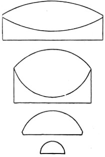
Fig. 122.—Powell and Lealand’s 1⁄12-in. Oil-immersion Objective, drawn on a scale of 6-1.
Messrs. Ross have made many important improvements and changes in the construction of their several series of achromatic objectives; the calculations and formulæ for which were made exclusively for them by Dr. Schrœder. The list is too long to quote, but most of these lenses are of a high-class character, and work with admirable precision. Among the best of their objectives, I can commend a 1-inch of 30° and two oil-immersions, a 1⁄8-inch of 1·20 and a 1⁄12-inch of 1·25 numerical aperture, each of which bear the highest oculars equally well; a good test, as I have always maintained, of excellence. Their 1⁄10-inch has a somewhat larger aperture, and therefore shows a fine image of the podura scale. The finish of Ross’s several series of objectives fully maintains the high character and reputation of this old-established firm of opticians.
Messrs. R. and J. Beck have bestowed great attention upon the improvement of their dry-objective series, much in demand for histological work, especially among the students of city hospitals, who usually commence their pathological work with the cheaper forms of objectives. In that case an inch objective of about 25° air angle, a ½-inch of not less than 40°, and a ¼-inch or 1⁄5-inch magnifying from 50 to 250 diameters, is quite sufficient for most of their work. For bacteriological research, Messrs. Beck supply a 1⁄6-inch immersion taken from a series, having a high aperture and a better finish at a moderate price. Their 1⁄10-inch immersion has in my hands proved a serviceable power for bacteriological research; it requires a good sub-stage illuminating achromatic condenser to obtain the best results.
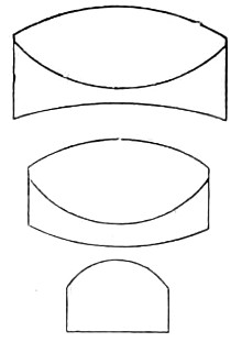
Fig. 123.—1⁄6-in. English Combination, largely used.
Messrs. Watson and Sons have much enhanced their reputation by the marked improvement lately brought about in the manufacture of their whole series of objectives. This probably is chiefly due to the introduction of the Jena glass into their manufacture, and which has enabled them to give increase of aperture to one series in particular, that of the para-chromatic, all of which in consequence are of very high quality. It is difficult to particularise their several objectives, the whole having special features in proportion to their magnifying powers, while much care seems to have been bestowed on them for the elimination of residual colour. A 1⁄8-inch with correction collar is comprised of a single deep and rather thick front lens, plano-concave flint, and double convex-crown for the middle and triple combination for the back, the latter consisting of two crown lenses cemented to a dense flint (Fig. 124) drawn to scale of 5-1, with lined portions intended to represent the flint, and white the crown glass lenses of the combination. The initial magnification of this objective is 83 diameters, and the numerical aperture ·94. This superior objective can be had for the small sum of £2. Another remarkably useful and cheap objective, their 1-inch numerical aperture 0·21, consists of two achromatic systems forming the front and back with the separation between them of about half an inch, and may also be especially recommended for students’ work.
In the accompanying diagram the lenses are drawn on too large a scale, and therefore the distance between the two combinations should be much greater.
Among the more useful of Watson’s series, the 1-inch, the ½-inch, and the 1⁄6-inch, together with the 1⁄8-inch dry-objective, and a 1⁄9-inch, will be found the most serviceable.
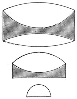
Fig. 124.—Watson’s 1⁄8-in. Objective Para-chromatic Combination, scale 5-1.
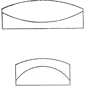
Fig. 125.—Watson’s 1-in. Achromatic Combination.
Messrs. Baker have their own series of objectives, most of which are so very nearly allied to those of the continental opticians; and what has been said of Zeiss’s and Leitz’s objectives may be taken to apply also to Baker’s, who have an established reputation for their histological series, all of which are well suited for students’ and class-room work.
Messrs. Swift and Son have a new series of objectives, semi-apochromatic and pan-aplanatic, most of which are excellent in quality and show increased flatness of field together with that of achromatism; the index of refraction in each series having been correctly determined together with exact radial focal distance, thus affording more available aperture. I may select for special commendation their 1⁄12-inch £5 5s. homogeneous immersion objective, which is in every way suitable for bacteriological work; its definition is very good, as is seen in a micro-photograph of podura scale, given further on. Their dry 1⁄6-inch can be had for £1 16s.—a marvel of cheapness. Of their general series the most useful for histological work are the ½-inch, the 1⁄3-inch at £1 12s., and their 1⁄5-inch of numerical aperture 0·87 at £3.
Mr. Pillischer, of Bond Street, has manufactured many excellent objectives. A fine homogeneous oil-immersion 1⁄12-inch numerical aperture 1·25 is worthy of special notice; it will be found suitable for bacteriological work; it has fine definition with a considerable amount of penetration.
A more intelligent idea of the magnifying power of the objective combined with the eye-piece will be gained by consulting the table given below; precision in this respect has long been a desideratum with microscopists.
Magnifying Powers of Eye-Pieces and Objectives.
A TYPICAL AND INITIAL SELECTION OF POWERS OF EYE-PIECES CALCULATED FOR THE 10-INCH TUBE-LENGTH.
Huyghenian Eye-pieces.
Name A B C D E F
of Maker. 0 or No. 1 2 3 4 5 6
Baker 6 8 12 15 — — Diameters.
Beck, R. & J. 4 8 15 20 25 not made. "
Leitz 5 6 7 8 10 12 "
Powell & Lealand 5 7·5 10 20 40 " "
Reichert 2·5 3·5 4 5 6·5 " " 24
Ross 3 8 12½ 20 25 40 " 25
Swift & Son 6 9 12 15 18 21 "
Watson & Sons 4 6 8 10 12 15 "
Zeiss 3 4 5·5 7 9 not made. "
Compensating Eye-pieces for use with Apochromatic Objectives.
Zeiss 2 4 8 12 18 27 Diameters.
This may be taken as a typical set, further treated of among Eye-pieces.
Initial Powers of Objectives calculated for the 10-inch Tube-length.
This is ascertained by dividing the distance of distinct vision 10 inches by the focus of the objective, thus—
Focus-inches 4 3 2 1½ 1 2⁄3 ½ 4⁄10 ¼ 1⁄5 1⁄6 1⁄8 1⁄12
Initial magnifying power 2·5 3·3 5 7·5 10 15 20 25 40 50 60 80 120 diameters.
A reference to the above table will at once show that the nomenclature of objectives expresses at once the initial magnifying powers, but as makers have great difficulty in so calculating their formulæ so as to obtain the exact power, these figures must be taken as approximate. Thus a ¼-inch, which should magnify 40 diameters if true to its description, might actually magnify a little more or less.
The magnifying powers of Zeiss’s and other apochromatic objectives can be ascertained by dividing the focal length of the objective in millimeters into 250 mm. (the distance of distinct vision), thus
Focus millimetres 24 16 12 4 3 2 1·5
Initial magnifying power 10·5 15·5 21 63 83 125 167 diameters.
The total magnification, when any eye-piece is working in conjunction with an objective, is ascertained by multiplying the initial power of the objective by that of the eye-piece.
The above calculations are all for a 10-inch tube-length. Should, however, a shorter or longer length of body be employed, the magnification can at once be ascertained by a proportion sum. If the magnification be 180 with 10-inch tube-length, what would it be with a 6-inch body—10 : 6 :: 180 = 108 diameters.
Abbe designed three different forms of eye-pieces: 1, the searcher eye-piece; 2, the working eye-piece; and 3, the projecting eye-piece. The Searcher is a negative form of low power. The working is both negative and positive, the positive form of which is constructed on a newer principle; while the projection is chiefly intended for microphotography, its field being small and its definition superlatively sharp. These are severally explained among eye-pieces.
High-Power Objectives.
Points of Importance for securing the best results with High-power Objectives.—Always give to the body-tube of the microscope the length for which the objective is corrected, 0·160 mm. for the short continental tube, and 0·250 mm. for the English tube (10-inch). Employ both dry and immersion objectives mounted for correction, commencing with a numerical aperture of 0·75 (that is about 100° in air). If the graduation is not given in thickness of cover-glass apply to the maker to correct this omission.
With the homogeneous oil-immersion objective it is highly necessary to utilise all marginal pencils of light, to optically unite the upper lens of the condenser with the preparation as well as the front lens of the objective by means of a liquid having the same index of refraction or at least equal to that of the immersion. Cedar Oil has been generally adopted for the purpose mentioned, the better way of using which is as follows: place a drop on the centre of the front objective, or on the top of the cover-glass, and then lower the objective by means of the coarse adjustment until it comes in contact with the oil, and carefully bring into focus by the fine adjustment. If the slide is held between the finger and thumb of one hand and moved from side to side, while the other hand is working the fine adjustment, there can be no danger of injuring either the objective or the specimen. Before putting the microscope away, take a fine camel-hair brush dipped in ether, alcohol, or methylated spirit, and carefully remove the oil from the objective and the glass cover of the object; a soft chamois leather or cambric pocket handkerchief will dry it off, or a piece of fine white blotting paper answers equally well. Should the lens come accidentally into contact with the Canada balsam, it must be very carefully removed either by ether or alcohol. The former is by far the safest, as alcohol, if not very carefully used, quickly dissolves out the balsam and loosens the cover-glass of the object.
Achromatic Condensers.
The Achromatic Condenser can no longer be classed among the accessories of the microscope, since it is an absolutely indispensable part of its optical arrangements. Its value, then, cannot be overrated, and the corrections of the lenses which enter into the construction of the condenser should be made as perfect as they can be made—in fact, as nearly approaching that of the objective as it is possible to make them. It may therefore be of interest to know something of the rise and progress of the achromatic condenser. In my first chapter I have noticed the earlier attempts made by Dr. Wollaston, whose experiments led him to fit to the underside of the stage of his microscope a short tube, in which a plano-convex lens of about three-quarters of an inch focal length was made to slide up and down (afterwards moved up and down by two knobs); to improve definition he placed a stop between the mirror and the lens. The stop was found to act better when placed between the lens and the object. From this improvement Dr. Wollaston enunciated that “the intensity of illumination will depend upon the diameter of the illuminating lens and the proportion of the image to the perforation, and may be regulated according to the wish of the observer.” Dujardin in France and Tully in England were at work in the same direction. The former a year or two later on contrived an instrument, which he termed an eclairage, to remedy the defects of Wollaston’s, and for illuminating objects with achromatic light. This was submitted for approval to Sir David Brewster, who, when the use of the achromatic condenser was first broached, used these encouraging words:—“I have no hesitation in saying that the apparatus for illumination requires to be as perfect as the apparatus for vision, and on this account I would recommend that the illuminating lens should be perfectly free from chromatic and spherical aberration, and that the greatest care be taken to exclude all extraneous light both from the object and eye of the observer.” This far-seeing observer in optical science has borne good fruit, and the outcome of his views is seen in the great development and improvement of the achromatic condenser. In 1839 Andrew Ross made his first useful form of condenser, and gave rules for the illumination of objects in an article written for the “Penny Cyclopædia.” These, epitomised, read as follows: 1. That the illuminating cone should equal the aperture of the objective, and no more. 2. With daylight, a white cloud being in focus, the object has to be placed nearly at the apex of the cone. The object is seen better sometimes above and sometimes below the apex of the cone. 3. With lamplight a bull’s-eye lens is to be used, to parallelise the rays, so that they may be similar to those coming from the white cloud. It has been seen that Mr. Lister foreshadowed the sub-stage condenser.
The early form of Ross’s condenser consists of two small brass tubes made to slide one in the other. To the outer one is attached a flat brass plate which slides underneath the stage of the microscope, and by means of a screw the adjustment of the axis of the illuminator is effected. The upper portion of the apparatus carries the achromatic combination, which by a rack and pinion movement is brought nearer to, or removed further from the object on the stage. The several parts of the illuminator unscrew, so that the lenses may be used either combined for high powers, or separated for low powers.
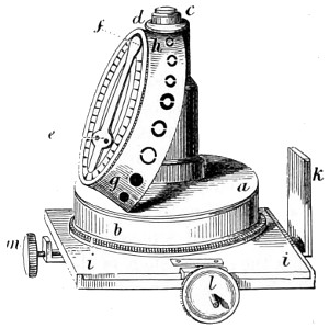
Fig. 126.—Original form of Gillett’s Achromatic Condenser.
Messrs. Smith & Beck greatly improved upon Ross’s condenser by adding another achromatic lens to the combination, three being employed when used with high-power objectives and two or even one with the lower, the adjustment and focussing being made by rack and pinion arrangement beneath the stage. Some further changes for the better were made in the condenser by Powell, and in 1850 an amateur microscopist, Mr. Gillett, fully grasping the value of controlling the cone of rays passing into the microscope, devised a new form of condenser, in connection with which a revolving series of diaphragms of different values were made to pass between the achromatic lenses and the source of light.
Andrew Ross constructed the first condenser on Gillett’s principle, and this proved to be one of the most successful pieces of apparatus contrived. Gillett’s Condenser consists of an achromatic lens c, about equal to an object-glass of one quarter of an inch focal length, with an aperture of 80°. This lens is screwed into the top of a brass tube, and intersecting which, at an angle of about 25°, is a circular rotating brass plate a b, provided with a conical diaphragm, having a series of circular apertures of different sizes h g, each of which in succession, as the diaphragm is rotated, proportionally limits the light transmitted through the illuminating lens. The circular plate in which the conical diaphragm is fixed is provided with a spring and catch e f, the latter indicating when an aperture is central with the illuminating lens, also the number of the aperture as marked on the graduated circular plate. Three of these apertures have central discs for circularly oblique illumination, allowing only the passage of a hollow cone of light to illuminate the object. The illuminator above described is placed in the secondary stage i i, which is situated below the general stage of the microscope, and consists of a cylindrical tube having a rotatory motion, also a rectangular adjustment, which is effected by means of two screws l m, one in front, and the other on the left side of its frame. This tube receives and supports all the various illuminating and polarising apparatus, and other auxiliaries.
Directions for using Gillett’s Condenser.—In the adjustment of the compound body of the microscope for using with Gillett’s illuminator, one or two important points should be observed—first, centricity; and secondly, the fittest compensation of the light to be employed. With regard to the first, place the illuminator in the cylindrical tube, and press upwards the sliding bar k in its place, until checked by the stop; move the microscope body either vertically or inclined for convenient use; and, with the rack and pinion which regulates the sliding bar, bring the illuminating lens to a level with the upper surface of the object-stage; then move the arm which holds the microscope body to the right, until it meets the stop, whereby its central position is attained; adjust the reflecting mirror so as to throw light up the illuminator, and place upon the mirror a piece of clean white paper to obtain a uniform disc of light. Then put on the low eye-piece, and a low power (the half-inch), as more convenient for the mere adjustment of the instrument; place a transparent object on the stage, adjust the microscope-tube, until vision is obtained of the object; then remove the object, and take off the cap of the eye-piece, and in its place fix on the eye-glass called the “centring eye-glass,”26 which will be found greatly to facilitate the adjustment now under consideration, namely, the centring of the compound body of the microscope with the illuminating apparatus of whatever description. The centring-glass, being thus affixed to the top of the eye-piece, is adjusted by its sliding-tube (without disturbing the microscope-tube) until the images of the diaphragms in the object-glass and centring lens are distinctly seen. The illuminator should now be moved by means of the left-hand screw on the secondary stage while looking through the microscope, to enable the observer to recognize the diaphragm belonging to the illuminator, and by means of the two adjusting screws to place this diaphragm central with the others: thus the first condition, that of centricity, will be accomplished. Remove the white paper from the mirror, and also the centring-glass, and replace the cap on the eye-piece, also the object on the stage, of which distinct vision should then be obtained by the rack and pinion, or fine screw adjustment, should it have become deranged.
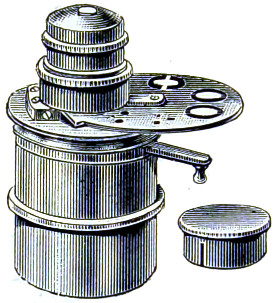
Fig. 127.—The Ross Improved Achromatic Condenser, with diaphragm stops.
The re-publication of the original directions is given with the view of showing what a clear conception Gillett had of the value of his invention. The careful directions given for centring must be regarded with interest, although nearly superseded by the centring screw arrangement in connection with the sub-stage. The best results, he goes on to say, will be secured by using the plain mirror and focussing the window-bar on the object, while a white-cloud illuminator will afford as much light as may be required. It is a mistake to suppose that direct light is more critical than indirect. As a rule, the student is given to over-illuminate the object. These questions will, however, be discussed further on.
Very many modifications of Gillett’s condenser have, since 1850, become known to microscopists. Ross’s present improved form (Fig. 127) is made to drop into the sub-stage of the microscope, and when adjusted, is an extremely efficient instrument. The optical part is similar to a 4⁄10-inch objective. It has two sets of revolving diaphragms, with apertures and stops for showing surface markings in a perfect manner.
Abbe’s Condenser.
The essential feature of this condenser is its short focus, which collects the light reflected by the mirror, so as to form a cone of rays of very large aperture, having its focus in the plane of the object.
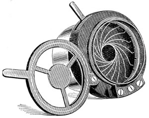
Fig. 128.—The Iris Diaphragm, and carrier for Stops.
The full aperture of the illuminating cone should only be used when finely granular and deeply stained particles (protoplasm, bacteria, &c.) are being examined with objectives of large aperture. In all cases the cone must be suitably reduced, either by an iris, or other form of diaphragm (central illumination). By placing the diaphragm excentrically, by means of rack-work attached to the carrier, the central rays are excluded and a certain extra-axial portion of the illuminating pencil falls upon the object (oblique illumination). When the diaphragm is thus excentrically placed, this oblique pencil can be directed from all sides by rotating the carrier round the optic axis. The central stop diaphragm shuts off all the axial and transmits only the marginal rays, thus producing dark-ground illumination. The iris diaphragm (Fig. 128) is so shaped that the edge of its smallest opening closely approximates the object-slide on the stage.
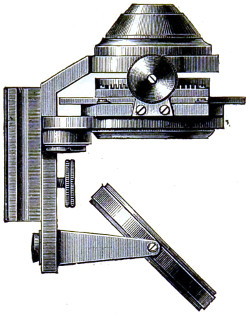
Fig. 129.—The Abbe Condenser, detached from the Sub-stage of the Microscope.
The Abbe condenser is the most popular form in use, for all purposes. Owing to the large aperture of the cone of light which it projects, it can be employed with the highest powers; by removing the top lens it can also be used with low powers. Dark ground illumination may be obtained with it up to a ¼-inch objective.
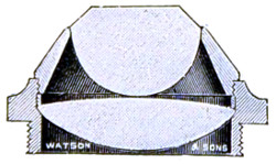
Fig. 130.—Optical Arrangement of Abbe Illuminator, 1·2 N.A.
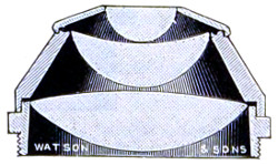
Fig. 131.—Optical Arrangement of Abbe Illuminator, 1·4 N.A.
The condenser is made in two forms of 1·2 and 1·4 numerical aperture by Messrs. Watson. The lenses are mounted in aluminium. Fig. 130 is in more general use, but by workers with high powers Fig. 131 is preferred, as it ensures the most oblique illumination with objectives of largest aperture. It is preferred for photo-micrographic purposes.
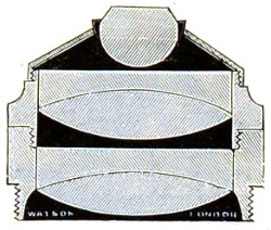
Fig. 132.—The Optical Arrangement of Watson’s Achromatic Condenser.
Watson’s Achromatic Condenser (Fig. 132), 1·0 numerical aperture, shown in section, although originally designed for use with the micro-spectroscope, is equally efficient for ordinary purposes. This condenser transmits a larger aplanatic cone of light than Abbe’s. It may therefore be employed with higher power objectives, and by removing the top lens it is just as useful a condenser for lower powers. Being constructed with lenses of an unusually large size, it is well adapted for use with the micro-spectroscope. It is certainly one of the best all-round condensers in use. The new Schott glass enters into the construction of the lenses, and these are mounted in aluminium.
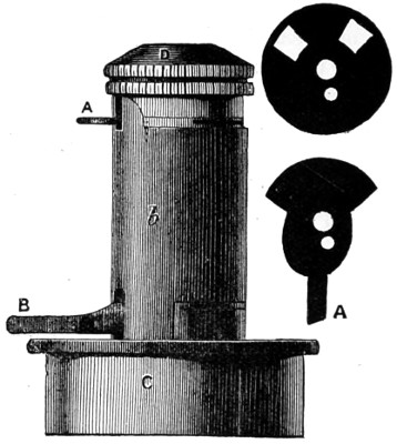
Fig. 133.—Powell’s Achromatic Condenser.
Many microscopists consider on the whole that Powell’s sub-stage apochromatic condenser with collar correction (Fig. 133) surpasses that of Abbe. The mechanical arrangement of Powell’s is very simple: the correction collar is similar to that of an ordinary objective, it has a steeper spiral slot and only half a revolution of movement; a long arc is fixed to the collar so that it may conveniently be reached by the finger. It is so constructed as to turn easily and smoothly at the slightest touch. The collar moves only the back lens of the combination, leaving the mount rigid. The diaphragms are regulated by A and B.
Fig. 134. Fig. 134a.
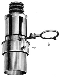
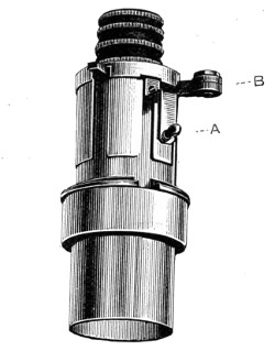
Fig. 134b.—Powell’s Apochromatic Oil Immersion Condenser, N.A. 1·40.

The object of the correctional movement is to increase the maximum aplanatic aperture of the condenser by separating the lenses. If the back of a wide-angled objective be examined when an object is illuminated by the full aperture of the condenser, the edge of the flame being in focus, it will be noticed that the illuminated portion of the back lens will be oval and pointed instead of circular. Also that when the condenser is racked up, although the external shape of the illuminated portion becomes more circular, two dark patches will appear on either side of the centre, showing the operation of the spherical aberration of the condenser. If under these circumstances the lenses are separated by means of the collar adjustment, the black spots will be closed up, and a circular and evenly-illuminated disc of illumination of a larger size will result. The wheel of diaphragms, or a series of graduated diaphragm discs to drop into a holder, is intended for critical work; the diaphragm can always be recorded, and the identical illuminating cone reproduced.
Hence we have a simple method of graduating apertures between any two contiguous diaphragms; if, for example, we place the lever to the left, so that the lens may be separated as far as possible, and use a No. 6 diaphragm, and if, on examining the object, it is thought that the illuminating cone is not large enough, and if when No. 7 is turned on it is found too much, we can go back to No. 6, and by turning the lever 60° towards the right, closing the lenses and increasing the power a little, we shall obtain an aperture somewhere between Nos. 6 and 7 diaphragm. Thus we can by means of the correction collar graduate the aperture with the facility as with an iris, and we can record any particular aperture with a degree of accuracy foreign to the iris. It must be admitted, however, that the cone of light transmitted by the condenser is a very small one.
Powell also supplies an apochromatic oil-immersion condenser, numerical aperture 1·40, but without collar correction; Fig. 134 shows the sliding tube lowered by arm A and cell B withdrawn for changing stops, which can be done without altering the focus of the condenser. Fig. 134a shows the cell B closed and raised by arm A close to the back lens of optical combination. In Fig. 134b six of the principal stops are shown. Powell’s dry apochromatic condenser, of nearly 0·9 aplanatic cone, is also very good; but the high price of all is a bar to their more general use. The speciality of these is the conversion of axis light into condensed oblique incident light by the refraction of the condenser.
Messrs. R. & J. Beck have various forms of achromatic condensers, some of which partake of a somewhat elaborate arrangement; others are simple and inexpensive, to suit the students’ microscope; as when the light of the concave mirror proves insufficient for any object requiring intense transmitted light, an achromatic condenser must be adapted to even the students’ form of microscope. The latest form of condenser (Fig. 135) is fitted with revolving stops and iris diaphragm, and other appliances for obtaining satisfactory results.
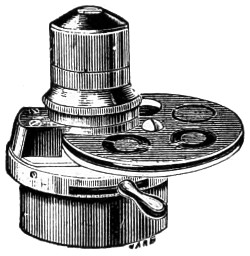
Fig. 135.—Beck’s newer form of Achromatic Condenser.
Beck’s Compound Illuminating Apparatus (Fig. 136).—It is useful in working with the microscope to be enabled to rapidly change the illumination, and for this reason this compound form of condenser has been constructed. It consists of an upper portion A, a wide-angle condenser, the aperture of which can be reduced at will by an iris diaphragm, moved by the lever B. This can be used for all other purposes. Below this diaphragm is a plate C, which can be swung back out of position at will, as shown in outline. Into a cell in this plate the stops D can be dropped, and the condenser can be used for dark field illumination, or for high powers as an oblique illuminator. A large-size polarising prism E, fastens to the plate C, and can be removed when not required. In this way any of the various modes of illumination may be separately or conjointly obtained.
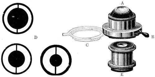
Fig. 136.—Beck’s Compound Condenser.
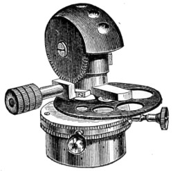
Fig. 137.—Beck’s Spherical Achromatic Condenser.
Their condenser (Fig. 137) has a large aperture, and facilities for rotating the series of diaphragms. It is available for either dry or immersion objectives up to 1·3 numerical aperture on diatoms, and wet or dry histological objects. The spherical form of the front is worked by a milled-head that rotates a series of lenses and diaphragms. It also avoids the inconvenience of having the connecting fluid drawn away by capillary attraction, as would be the case if mounted on a flat surface. It is also less in the way of the sub-stage movements.
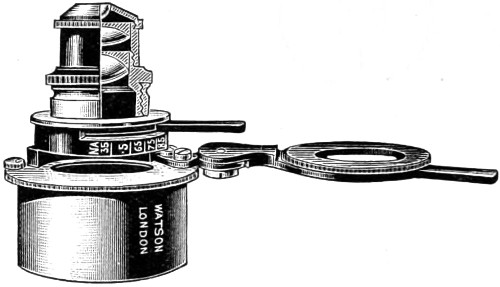
Fig. 138.—Watson’s Parachromatic Condenser.
The Parachromatic Condenser of Messrs. Watson (Fig. 138) was made to meet a demand for a condenser giving a large solid cone of illumination free from colour. The optical part of this condenser consists of a full hemispherical front lens, and the middle and back combinations of such forms as to produce the necessary corrections. The Jena phosphate crown and silicate flints are used in its manufacture, and to these are due its special qualities. The total aperture of the condenser is 1·0, and it yields an aplanatic aperture of ·90 numerical aperture. The magnifying power is 2⁄7ths of an inch. From this it will be seen that it is especially suitable for use with high-power objectives.
It can also be employed without the front lens, when the magnifying power is 4⁄10ths of an inch, and the numerical aperture ·35. It is mounted in an exceedingly convenient manner, the iris diaphragm being fitted in such a way as to be absolutely central with the optical system.
The arc through which the handle controlling the iris travels is divided, and indicates the aperture at which the condenser may be working at any time. An important feature in this condenser is that it is almost wholly free from colour. As a rule condensers of the same form are found difficult to work with, because of the small diameter of the field or back lens. This difficulty has been successfully overcome by increasing the size of this lens, and the whole of which is fully utilised.
Most London opticians have their own especial form of achromatic condenser, designed for and fitted to their several stands and objectives, varying from a small price to the more expensively-fitted accessories.
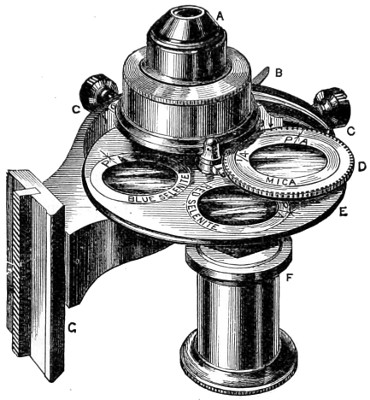
Fig. 139.—Swift’s Illuminating Polarising Apparatus.
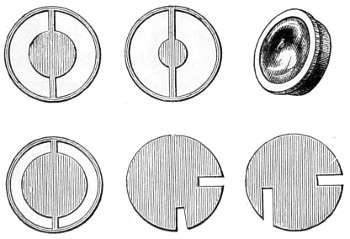
Fig. 139a.—Swift’s Diaphragms and Central Stops.
Messrs. Swift’s illuminating apparatus (Fig. 139) is conveniently supplied with numerous useful appliances. The optical combination A is computed to be used as an effective spot lens from a 3-inch objective up to a sixth. C C are two small milled heads by means of which the optical combination A is centred to the axis of the objective. The revolving diaphragm E has four apertures for the purpose of receiving central stops, oblique light discs, and selenite films. D is a frame carrying two revolving cells, into one of which a mica film is placed, which can be revolved with ease over either of the selenites below, whereby changes of colour can be obtained in experimenting with polarised light. The darts and P A’s indicate the position of the positive axis of the mica and selenite films, and by this means results can be recorded, etc. Either of the revolving cells can be thrown into the centre of the condenser, and there stopped by means of a spring catch; when so arranged the mica film, &c., may be revolved in its place by turning the cell D, as both cells are geared together with fine racked teeth. F is a polarising prism mounted on an eccentric arm, rendered central when in use, or thrown out, as seen, when out of use. G is the rack dove-tail slide for indicating and focussing the condenser on the object. The advantages associated with this condenser consist in having the polarising prism, selenite films, dark-ground, and oblique light stops, so that they may be brought close under the optical combination.
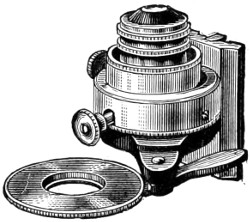
Fig. 140.—Baker’s Nelson Achromatic Condenser.
Baker’s Nelson Condenser, shown in Fig. 140, is intended for use with their medium instruments. It has, however, many pieces of apparatus essential to those of a higher class. It is applicable, indeed, to all instruments having sufficient depth beneath the stage to receive it. It comprises an achromatic combination of 90° aperture, available with all powers up to 1⁄8-inch tinted glass for neutralising the yellow rays of artificial light, focussing adjustment, dark-ground illuminator, large diaphragm with rotating tube to carry oblique light stops, small wheel of apertures, polarising prism with two selenite films, clear aperture, and oblique light-shutter for low powers.
Baker’s Students’ Condenser (Fig. 141) is designed to take the place of Abbe’s, and costs much less. It transmits a larger aplanatic cone of light, and can be used either with high or low powers by removing the front lens. It is equally useful for photo-micrographic work.
Mr. J. Mayall’s semi-cylinder or prism for oblique illumination (Fig. 142) is a convenient form, as it permits of the semi-cylinder being tilted and placed excentrically; in this manner, without immersion contact, and by suitable adjustment, a dry object can be viewed with any colour of monochromatic light. If placed in immersion contact with the slide, the utmost obliquity of incident light can be obtained. Objects in fluid may be placed on the plane-surface of the semi-cylinder, and illuminated by ordinary transmitted light, or rendered “self-luminous” in a dark field, as with the hemispherical illuminator or Wenham’s immersion paraboloid. A concave mirror with a double arm is quite sufficient to direct the illuminating pencil. This semi-cylinder was originally made by Tolles, of Boston, for measuring apertures, but, at Mr. Mayall’s suggestion, Messrs. Ross mounted it as an illuminator.
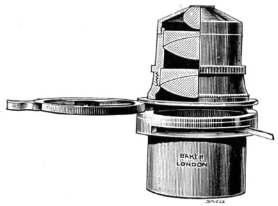
Fig. 141.—Optical Arrangement of Baker’s Abbe Condenser.
The spiral slot should be fixed close beneath the larger lens of the condenser, and when properly arranged will be found a convenient mode of obtaining oblique light.
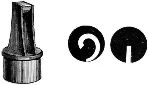
Fig. 142.—Mayall’s Semi-Cylinder Illuminator and Spiral Diaphragms.
The Webster-Collins Universal Condenser (Fig. 143) is so well known that it scarcely calls for any lengthy description. It is an inexpensive form of condenser, designed in the first instance for use with the students’ microscope. It is fitted into the sub-stage; has an iris diaphragm as well as a series of revolving diaphragms moved by a milled head screw arrangement.
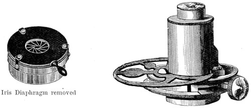
Fig. 143.—The Webster-Collins Universal Condenser.
Oblique Illumination.
Wenham’s Parabolic Condenser.—Mr. Wenham’s many useful additions to the microscope and its accessories demand especial notice. When mention is made of the various immersion condensers (illuminators, as he preferred to call them), his original right-angled prism, his truncated hemispherical lens, his immersion paraboloid, and his reflex illuminator, in which rays beyond the angle of total reflexion are utilised by reflex action from cover-glass on to the surface of the object, every one of these well-devised inventions will always be spoken of in terms of praise. All in their turn conferred a great service upon the microscope, and enabled the student to clear up difficulties that stood in the way of developing structure when achromatic lenses and dry-objectives were considered perfect. The superior illumination of the object was wholly due to, and effected by, reflected rays from the object to the aperture of the objective, and obviously, reflex action could only take place with dry-objectives. This reflex action must be regarded as Mr. Wenham’s special discovery. It must be observed, however, that it is not the same as the more modern achromatic appliances used for throwing direct rays upon the object, and which proved the existence of apertures capable of direct transmission up to 27° measured in the body of the front lens.
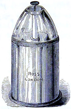
Fig. 144.—Wenham’s Parabolic Reflector.
The most practical of Mr. Wenham’s inventions is probably the hemispherical lens, since adopted by Messrs. Ross in connection with their excellent Zentmayer stand, and which has proved eminently serviceable. But the fact is that devices of the kind for obtaining direct oblique light require a thin stage, and therefore most of those who possess the earlier-made microscope stand would doubtless hail the appearance of any appliance which will convert axial light into oblique light; as by so doing the possessors of such instruments, in which the stage is generally of considerable thickness, would enjoy the pleasure of seeing the best resolution it is possible to get with their dry-objectives.27
Wenham’s Parabolic Reflector.—This will be better understood by reference to Fig. 145, which represents it in section A B C, and shows that the rays of light r r′ r′′, entering perpendicularly at its surface C, and then reflected by its parabolic surface A B to a focus at F, can form no part of the largest pencil of light admitted by the object-glass and represented by G F H; but an object placed at F will interrupt the rays and be strongly illuminated. A stop at S prevents any light from passing through direct from the mirror.
In the microscope the parabolic reflector fits into the cylindrical fitting under the stage, and the adjustment of its focus upon the object is made by giving it a spiral motion when fitted in—that is, carefully pushing it up or down at the same time that it is turned round by the milled edge B B. It must then be focussed by the rack and pinion motion. As the rays of light must be parallel when they enter it, a flat mirror, which in this case should be added to the instrument, is generally used; daylight will then require only direct reflection, but the rays from an artificial source will have to be made parallel by placing a side condenser between the light and the mirror, about 1¾ inch from the former and 4½ inches from the latter. Nearly the whole surface of the mirror should be equally illuminated; this may be tested by temporarily placing upon it a card or piece of white paper. Parallel rays can also be obtained from the concave mirror, if the light is placed about 2½ inches from it. Dark-ground illumination is not suitable for very transparent objects—that is, unless there is a considerable difference in their index of refraction, or they are pervaded by air-cells.
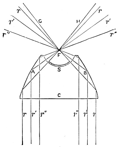
Fig. 145.—Parabolic Reflector.
One very remarkable example of this may be seen in the tracheal system of insects. If any of the transparent larvæ of the various kinds of gnat be mounted in gelatine and glycerine jelly, slightly warmed but not enough to kill the insect outright, about the third day the fluids circulating in the body will be absorbed and replaced by air. Illuminated by the parabolic condenser, and viewed with a binocular microscope, and a low power, the gnat-larva becomes a superb object. The body of the insect is but faintly visible, and in its place is displayed a marvellous tracheal skeleton, with the tubes standing out in perspective, shining brilliantly, like a structure of burnished silver. Unfortunately, such objects are not permanent, for when the whole of the water dries up, the tracheal tubes either collapse or become refilled with fluid.
As to the blackness of field, and luminosity of the object, this depends upon excess of light from the paraboloid received beyond the angle of aperture of the object-glass. It is found in practice that more and more of the inner annulus of rays from the paraboloid has to be stopped off, until at last, with high-angled objectives, it is scarcely possible to obtain a black field.
The light, on the whole, most suitable for this method of illumination is lamp, the rays of which should in all cases be rendered more parallel by means of a large plano-convex lens, or condenser.
Fig. 146.—Wenham’s Hemispherical Lens.
Wenham’s Immersion Condenser.—Mr. Wenham, in the year 1856, described various forms of oblique illuminators, one of which was an immersion; a simple right-angled prism, connected by a fluid medium of oil of cloves. This, however, was abandoned for a nearly hemispherical lens connected with the slide, and although an improvement, did not touch the point of excellence Mr. Wenham was looking for. Ultimately he adopted a semi-circular disc of glass of the exact form and size represented in the drawing, Fig. 146, having a quarter-inch radius, with a well-polished rounded edge, the sides being grasped by a simple kind of open clip attached to the sub-stage, the fluid medium used for connecting the upper surface with the slide being either water, glycerine, or oil; an increase of oblique illumination being obtained by swinging the ordinary mirror sideways. By means of an illuminator of the kind difficult objects mounted in balsam are resolved. This simple piece of glass collects and concentrates light in a marvellous manner, and is by no means a bad substitute for some of the more costly forms of achromatic condenser. It can be used either in fluid contact with the slide, or dry, as an ordinary condenser.
Mr. Wenham subsequently contrived a small truncated glass paraboloid, for use in fluid contact with the slide; water, glycerine, oil, or other substance being employed as a contact medium. The rays of light in this illuminator, being internally reflected from a convex surface of glass, impinge obliquely on the under surface of the slide, and are transmitted by the fluid uniting medium, and internally reflected from the upper surface of the cover-glass to the objective. To use the reflex illuminator efficiently it must be racked up to a level with the stage. The centre of rotation is then set true by a dot on the fitting, seen with a low power, a drop of water is then placed on the top, and upon this the slide is laid. Minute objects on the slide must be found either by the aid of a low power, by their greater brilliancy, or by rotating the illuminator; the effect on the podura scale is superb, the whole scale appearing dotted with bright blue spots in a zig-zag direction. Objects for this illuminator should be especially selected and mounted.
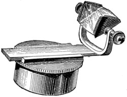
Fig. 147.—The Amici Prism.
The Amici Prism, originally designed for oblique illumination, consists of a flattened triangular glass prism, the two narrower sides of which are slightly convex, while the third or broadest side forms the reflecting surface. When properly used, it is capable of transmitting a very oblique pencil of light. The prism is either mounted, as in Fig. 147, for slipping into the fitting of the sub-stage, or on an independent stand, as arranged for Powell’s microscope, page 85, Fig. 56.
Method of Employing the Achromatic Condenser to the Greatest Advantage.
Its Illumination.—Good daylight is the best for general work. The microscope should be placed near a window with a northern aspect. Direct sunlight should never be utilised; the best light is that reflected from a white cloud. A good paraffin lamp is the most serviceable artificial source of light, and it is quite under control. As an illuminant more often brought into requisition in the smoky atmosphere of towns, the paraffin lamp is on the whole the handiest and the most useful. If gas-light can be brought into use as suggested for micro-photography, with the incandescent mantle, it will be found to be the purest and best form of artificial illumination for the microscope. Among paraffin lamps those constructed by Baker and Swift are all that can be desired.28
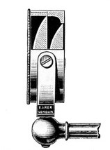
Sectional view of the Optical Arrangement of the Aplanatic Bull’s-eye Lens, fitted in gymbal on the front of the lamp.
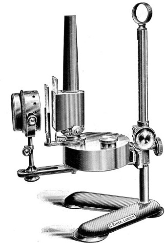
Fig. 148.—Baker’s Microscope Lamp.
As the chimneys of these lamps are made of metal, and blackened, no reflected light disturbs the eye. Care must be taken to have the wick evenly trimmed; the metal chimney has a glazed front, giving exit to the rays of light, the flat of the flame being used with low powers, and the image of the flame being reflected by a plane mirror to give equal illumination of the whole field. In working with high powers, the lamp is turned with the flame edge-wise, and at the same time the mirror must be dispensed with. By working, as it is termed, directly on the edge of the flame, the illumination is greatly increased, and a band of light can be concentrated on any part of the preparation it is desired to make a careful study of.