Part 1 — CHAPTER III. (continued 2)
Reading edition
To obtain the best results, time and care must be given to the illumination of the object. The lamp and microscope having been placed in position, a low power is first used and the smallest diaphragm. On looking through the microscope it will probably be observed that the image of the diaphragm is not in the centre of the field; by moving the centring screw of the condenser this may be adjusted. The low power is then replaced by a high power, the largest diaphragm used, and the bacteria or diatom brought into focus. The diaphragm must now be replaced by one of medium size, and by racking the condenser up and down, a point will be arrived at when the image of the edge of the flame appears as an intensely bright band of light. If this is not exactly in the centre of the field the centring screw of the condenser must again be adjusted. With regard to the use of diaphragms, various sizes should be tried while focussing with the fine adjustment, at the same time using the correction colour; in this way we obtain the sharpest possible image. When the condenser has been accurately centred, it will still be necessary to focus it for each individual specimen, so as to correct for difference in the thickness of slides and the layers of mounting medium. Correction for different thickness of cover-glasses must be made by the aid of the collar adjustment in the following way: a high-power eye-piece is substituted for the ordinary eye-piece, and the faults in the image will thereby be intensified. By moving the collar completely round, first in one direction and then in the other, while carefully observing the effect of the image, it will be seen to become obviously worse whichever way the collar is turned. The collar must then be turned through gradually diminishing distances until an intermediate point is reached at which the best image results with the high-power eye-piece, and on replacing this by the low-power eye-piece the sharpest possible image will be obtained.
Effect of the Sub-stage Condenser.—The sub-stage condenser gives the most powerful illumination when it has been racked up until it almost touches the specimen. It produces a cone of rays of very short focus, and the apex of the cone should correspond with the particular bacterium or group of bacterias under observation. The effect of the condenser without a diaphragm is to obliterate what Koch has termed a structure picture. If the component parts of a tissue section were colourless and of the same refractive power as the medium in which the section is mounted, nothing would be visible under the microscope. As, however, the cells and their nuclei and the tissues do not differ in this respect, the rays which pass through them are diffracted, and an image of lines and shadows is developed. If in such a tissue there were minute coloured objects, and if it were possible to mount the tissue in a medium of exactly the same refractive power, the tissue being then invisible, the detection of the coloured objects would be much facilitated. This is exactly what is required in dealing with bacteria which has been stained with aniline dyes, and the desired result can be obtained by the use of the sub-stage condenser.
If we use the full aperture of the condenser the greatly converged rays play on the component parts of the tissue, light enters from all sides, the shadows disappear, and the structure picture is lost. If now a diaphragm is inserted, so that we are practically only dealing with parallel rays, the structure picture reappears. As the diaphragm is gradually increased in size the structure picture gradually becomes less and less distinct, while the colour picture, the image of the stained bacteria, becomes more and more intense. When, therefore, bacteria in the living condition and unstained tissues are examined, a diaphragm must be used, and when the attention is to be concentrated upon the stained bacteria in a section or in a cover-glass preparation the diaphragm must be removed and the field flooded with light—(Crookshank).
The wide-angle condenser, it will be understood, consists of a combination of lenses, which concentrate all the light entering them to a small point, and the condenser must be so accurately focussed that this brilliant cone of light, when it emerges from the upper lens of the condenser, falls upon the object from all directions, forming a wide-angle cone of light, at the apex of which the object must be placed (see Fig. 149). That is to say, the object is illuminated by a cone of rays passing through it in all directions.
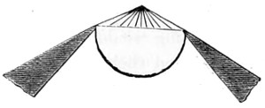
Fig. 149.—Front Lens of Condenser.
There are, however, objects which require a fully illuminated field, when the lamp should be turned round and the Herschel lens condenser (shown in section, Fig. 148) should be used to collect the light and throw it upon the mirror. For moderate powers, as a four-tenth or one-fifth, the condenser should be used a little below the focus to give an even illumination over the whole field. Moreover, as to the use of the condenser for defining general objects, it must be borne in mind that to show different kinds of structure different apertures in the iris diaphragm are necessary, and that whereas some objects show their structure better with a large angle of light cut down in intensity by the use of blue glass, others show better with a small pencil of direct rays. For the resolution of diatoms it is often necessary to use oblique light only, and for this purpose diaphragms with central patches are used, the iris diaphragm being opened to its full extent. An annular ring of oblique light emerges from the condenser upon the object, and it is in this manner also that dark-ground illumination is obtained with moderate and low powers.
THE DIAPHRAGM.
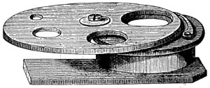
Fig. 150.—The Diaphragm.
The early form of diaphragm in use was that shown in Fig. 150.
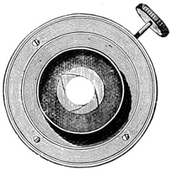
Fig. 151.—Shutter Diaphragm.
It consists simply of a circular brass plate with a series of circular openings of different sizes, arranged to revolve upon another plate by a central pin or axis, the last being also provided with an opening as large as the largest in the diaphragm-plate, and corresponding in situation to the axis of the microscope body. The holes in the diaphragm-plate are centred and retained in place by a bent spring in the second plate, which rubs against the edge of the diaphragm-plate and catches in a notch. The blank space shuts off the light from the mirror when condensed light is about to be used. It is usually made to fit in under the stage of the microscope. This has been almost superseded by the iris diaphragm, originally designed by Wales, of America. It was made by this optician for his working students’ microscope. An early form of the iris diaphragm is seen in Fig. 151. By pressing upon the lever handle at the side the aperture gradually closes up, and without for a moment losing sight of the object under examination.
The Mirror.
The mode in which an object is illuminated is, in the words of the late Andrew Ross, “second only in importance to the excellence of the glass through which it is seen.” To ensure good illumination the mirror should be in direct co-ordination with the objective and eye-piece; it must be regarded as a part of the same system, and tending by a combined series of acts to a perfect result. Illumination of the object is recognised as of three kinds or qualities—reflected, transmitted, and refracted light. For the illumination of transparent objects, transmitted light is brought into use; for opaque objects, reflected light is needed.
The mirror should be about 2½ or 3 inches in diameter, and it must not be fixed, but made to slide up and down the stem under the stage, so that the rays of light emanating from it may be brought to a focus. The utility of the mirror is so obvious that it is occasionally passed over in silence by writers. To myself it appears to be an important accessory of the microscope, and I shall therefore proceed to combine theory with practice in what I have to say with regard to the mirror.
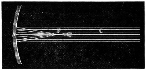
Fig. 152.—Principal Focus of Mirror.
The microscope mirror should be the segment of a true sphere, and its centre that of a true curvature. If the mirror has a true circular boundary, the central point on line A (Fig. 152) of the reflecting surface, is the pole of the same. The line A C is known as its principal axis, and any other straight line through C, which meets the mirror, is its secondary axis. When the incident axis is perfectly parallel to the principal axis, the reflected rays converge to a point F, its principal focus. So much for the theory of the mirror. Now we come to its practical use.
Simple as the mirror of the microscope may appear to be, if the curve of the surface is not perfect, it will yield a secondary reflection or double pencil of rays. The plane mirror will occasionally be found to emit more than one reflection of the lamp-flame; this we find may be corrected by rotating the mirror in its cell. Many years ago I proposed to meet a difficulty of the kind by arranging a rectangular prism on a separate stand, shown in Fig. 153, consisting of a prism A B, mounted in gimbal C, D, and E, secured to a brass tube G, fitted to the stem, and thus made to take the place of the mirror.
The direct method of employing the mirror, that more generally resorted to, is by reflecting rays from the concave surface; the plane surface is preferred when the condenser is used. Whichever is employed, it should not be forgotten that the optic axis must be preserved throughout, and so brought to the centre of the open tube of the microscope. Another method is to interpose a bull’s-eye lens, and in this way supply the mirror with a beam of parallel rays of light. The plane side of the bull’s-eye lens should be turned towards the lamp, so that lamp, bull’s-eye, sub-stage condenser, and objective, are brought into an exact line, the bull’s-eye being set at right-angles to the line. A piece of thin white paper held across the bottom of the sub-stage will serve to show whether the rays of light are fairly parallel. The next care is to focus the object on the stage, and then the sub-stage condenser on the slide; further correction should be made by means of the centring screws of the sub-stage, or by moving the bull’s-eye lens or lamp slightly, thus perfecting the arrangements for working with parallel rays of light.
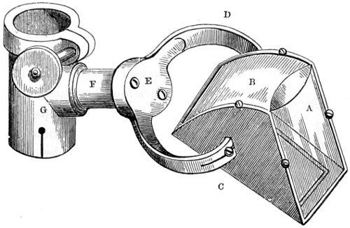
Fig. 153.—Rectangular Prism.
Accessories of the Microscope.
The accessories and appliances of the microscope have become so very numerous, that any attempt to describe them and explain the uses to which they are put would demand more space than I find myself in a position to bestow upon them. I must therefore confine my remarks to those accessories in more general use.
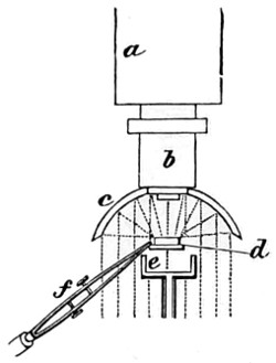
Fig. 154.—The Lieberkühn.
Having described the method of employing transmitted light, I have a few words to add with regard to the illumination of opaque objects by reflected light. A very early and efficient form of opaque illumination is the well-known Lieberkühn. This has not been entirely surpassed by more recent inventions. The concave speculum termed a Lieberkühn, so named after its celebrated inventor, directly reflects down upon the object the light received either from the mirror or bull’s-eye lens. It consists of a silver cap, which slides over the objective (Fig. 154), a indicating the lower part of the compound body, and b the objective over which slides the Lieberkühn, c; the rays of light are collected to a focus upon the object at d. The object may either be mounted on a slip of glass, or held by the stage-forceps, f; if very small, or transparent, it may be gummed to the dark well, e, or mounted on a Beck’s opaque disc-revolver.
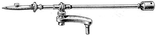
Fig. 155.—Stage Forceps, for holding objects while under examination.
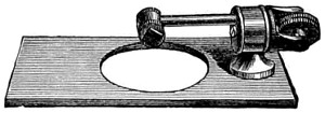
Fig. 156.—Beck’s Disc-holder.
This holder will be found useful for the examination of opaque or other objects that cannot be conveniently held by the stage forceps, the specimen being temporarily attached to it by gum or gold size. The holder is intended to rotate, so that every portion of the object can be brought into view. In this way it will be found useful in the study of insects, foraminifera, &c.
With the Lieberkühn, however, the illumination of opaque objects must be more or less one-sided, and therefore, the silver side-reflector has superseded it for general use (Fig. 157). To ensure a more perfect illumination of the object, the bull’s-eye lens should also be used. Mr. Sorby devised a reflector to fit over the objective. It consists of a semi-circular cap; is, in short, a modification of the parabolic reflector. The light from the mirror can, by slightly varying its inclination, be brought into use with this reflector.
The silver side-reflector is usually made with a ball-and-socket joint, so that it can be turned in any direction. It is secured to the stage of the microscope by the pin, which drops into a hole purposely drilled to receive it, and facility given for turning up and down, or in any position. If daylight is used the microscope should be placed in such a position that the light from a white cloud falls upon the speculum, but the light of the lamp is far more manageable for use with the reflector.
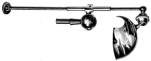
Fig. 157.—Silver Side-reflector.
The Lieberkühn is only intended to be used with low powers—a 2-inch, ½-inch and a 2⁄3-inch. Such objects as the elytra of the diamond and other beetles are well suited for examination.
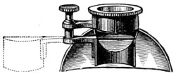
Fig. 158.—Sorby’s Modification of the Parabolic Reflector.
While experimenting with a parabolic reflector (Fig. 158), Mr. Sorby saw the value of examining objects under every kind of illumination. As on viewing specimens of iron and steel with this reflector he found that, from the great obliquity of the illumination obtained, the more brilliantly polished parts of the specimen reflected the light beyond the aperture of the objective, and these could not be distinguished from those parts which absorbed light, he thereupon proceeded to place a small flat mirror in front of the objective, and cover half its aperture, and at the same time stop off by means of a semi-cylindrical tube the light from the parabolic reflector. This arrangement produced the reverse appearance of that first employed, and it proved to be a useful aid in determining structure.
The Bull’s-eye Condensing Lens.
This accessory is brought into constant use for the purpose of converging rays from a lamp or mirror; or, for reducing the diverging rays of the lamp to parallelism with the parabolic illuminator, or silver side-reflector. The form in use is a plano-convex lens of about three or four inches in focal length (Fig. 159). It is usually mounted on a brass stand, so that it may be placed and turned in any direction, and at any height. When used by daylight, its plane side should be turned towards the object, and the same position maintained when used for converging the rays of light from the lamp; but when used with the side-reflector the plane side must be towards the lamp. Much attention has been paid to this very necessary accessory, the bull’s-eye lens. A doublet has been brought into use which has increased the value of the bull’s-eye condenser in bacteriological research, and in micro-photography generally.
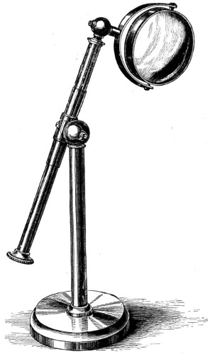
Fig. 159.—Bull’s-eye Lens.
“During a recent investigation of the spherical aberration in doublets, it was believed to be impossible to construct a doublet of the form known as ‘Herschel’s doublet’ free from aberration, although these doublets figure in many books on optics. In a condenser made by Baker the aberration is reduced to a minimum, 27 per cent. less than Sir John Herschel’s. This doublet, it appears, differs from Herschel’s both in the ratio of the radii of the meniscus, and also in the ratio of the foci of the two lenses; indeed, the only point of similarity is in the first lens, which is crossed. To test this, project the image of the flat lamp-flame on a piece of white card with a plano-convex lens (the field-lens of the Huyghenian eye-piece), use first the convex side and then the plane side towards the card, the lamp being placed about 6 feet from the lens. Focus the lamp-flame as sharply as possible, and a circular halo of misty light will be seen to surround the lamp-flame; but when the plane side of the lens is made to face the card this halo of misty light will be seen to be greatly reduced, and the brightness of the image of the flame proportionately increased. If the lens, then, were strictly aplanatic there should be no misty halo, all the light being concentrated in the image of the lamp-flame, and the image of maximum brightness. In short, the diameter of the halo or misty light is the measure of the spherical aberration. If the condenser referred to above, having the form of minimum aberration for two planes, be compared in the same manner with an ordinary single bull’s-eye of the same focus, the diameter of the misty halo will be found reduced to a radius of about 1⁄5-inch, but, with this new condenser there is a further reduction, so that the radius of the misty halo measures only 1⁄20-inch. These experiments are instructive, because the brightness, or the mistiness of the microscopical image is an associated phenomenon.”29
A sectional view of the optical arrangement of Baker’s aplanatic bull’s-eye doublet is shown, together with lamp, in Fig. 148.
The Microscope Lamp.—The introduction of paraffin into household use has somewhat modified our views with regard to the most suitable artificial source of illumination. Good paraffin burns with a whiter and purer flame than colza oil, and consequently is less liable to fatigue the eyes. The first cost of the lamp is trifling; for a moderate sum a handy form of lamp can be had, mounted on an adjustable sliding ring stand, and with a porcelain, metal or paper shade, to protect the eyes from scattered rays of light. All opticians supply accepted forms of lamps.
To give the increased effect of whiteness to the light (“white cloud illumination” as it is termed), take a piece of tissue paper, dip it into a hot bath of spermaceti, and, when nearly cold, cut out a circular piece and secure it over the largest opening in the diaphragm plate. This will be found to materially moderate and soften the light.
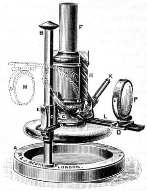
Fig. 160.—Beck’s Complete Lamp.
Beck’s Complete Lamp is constructed especially for delicate microscopical work. It has a burner giving a flat flame; this can be rotated to enable the edge or the flat of the flame to be used; likewise a metal chimney with two apertures, in which 3 × 1 glass slips slide; either white or coloured glasses may be used. A Herschel aplanatic condenser is carried on a swinging arm, which rotates around the lamp flame as a centre, and can be clamped in any position. The whole lamp has a raising and lowering motion, with a spring clamp to hold it in any position. The lamp is so designed that at its lowest position the flame is only three inches from the table. Here the microscopist is furnished with a lamp which will accomplish all he may require with regard to illumination.
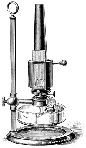
Fig. 161.—Watson’s Microscope Lamp.
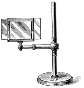
Fig. 162.—Glass Holder for carrying Coloured Glasses.
Watson’s lamp (Fig. 161) has a metal chimney, and is somewhat simpler in structure than those already referred to. For the student, the simpler and cheaper form will answer every purpose. A glass holder for carrying various tinted slips of coloured glass to act as a screen or modifier of the light is much employed, and assists in determining fine structures (Fig. 162).
Nose-pieces and Objective Changers.
A convenient appendage to the microscope is the rotating nose-piece, invented by Mr. Charles Brooke, F.R.S., and intended to carry two or more objectives, whereby a saving of time is effected, and the trouble of repeatedly screwing and unscrewing is avoided. In the application of the nose-piece attention should be given to centring. Messrs. Baker’s objective changer is intended to facilitate the placing and replacing the nose-piece in position. This adaptation consists of a milled head, acting on three jaws, having a universal screw thread, a decided improvement on the screw. Zeiss has adopted a tube-sliding objective changer with centring adjustments. Messrs. Watson met the difficulty of centring by making the nose-piece a part of the body-tube of their microscopes (Fig. 163). This, when adapted to the shorter body of the students’ microscope, fully compensates for want of length.
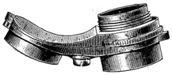
Fig. 163.—Watson’s Centring Nose-piece of Microscope.
Their triple nose-piece is constructed with much care, and when in use is found very effective. It is manufactured of that very light metal aluminium, and which minimises the strain produced by the heavier brass nose-piece.
Finders.—The finder affords a necessary and useful means of registering the position of any particular object, so that it may be readily found again at any subsequent period. In the work of examination the finder will save time when making a special research, extending over a considerable surface.
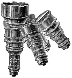
Fig. 164.—Triple Nose-pieces.
That the finder has been of use may be surmised from the number invented and figured in the “Journal of the Royal Microscopical Society.” By far the most useful form is that of graduating the plates of the mechanical stage, dividing a certain portion into 100 parts. Powell and Lealand have adopted this system in their No. 1 stands, while Baker and Watson have added a graduated scale on silver to 1⁄100th mm. as a finder, and also a stage micrometer in 1⁄10th and 1⁄100th of a millimetre, together with a Maltwood finder for lodging the position of any desired portion of a specimen under examination.
The Maltwood finder (Fig. 165) can be used with any microscope, and without a mechanical stage. This useful finder continues to occupy a permanent place among the accessories of the microscope. It consists of a glass slide, 3 × 1¼ inches, on which is photographed a scale occupying a square inch; this is divided by horizontal and vertical lines into 2,500 squares, each of which contains two numbers marking its “latitude,” or place in the vertical series, and its “longitude,” or place in the horizontal series. The scale is in each instance an exact distance from the bottom and left-hand end of the glass slide; and the slide, when in use, should rest upon the ledge of the stage of the microscope, and be made to abut against a stop, a simple pin, about an inch and a half from the centre of the stage.
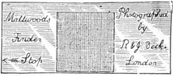
Fig. 165.—Maltwood’s Finder.
Dr. Pantacsek’s finder appears to have some advantage over Maltwood’s, but it cannot be used with the same facility, and therefore will not displace an old favourite. The Amyot finder I have long had in use; it is efficient and inexpensive—can indeed, if misplaced or lost, be replaced by the aid of the square and compasses.
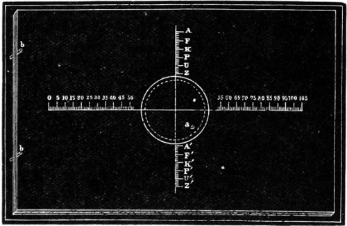
Fig. 166.—Amyot’s Object Finder.
The Okeden finder consists of two graduated scales, one vertical, attached to the fixed stage-plate, the other horizontal, attached to an arm carried by the intermediate plate; the first of these scales enables the worker to “set” the vertically-sliding plate to any determinate position in relation to the fixed plate, while the second gives the power of setting the horizontally-sliding plate by that of the intermediate.
Micrometers.—It is of the utmost importance to have a means of measuring with accuracy the objects, or part of objects, under observation. The most efficient piece of apparatus for the purpose is the micrometer eye-piece, the earlier form of which, Jackson’s, has been described under the heading Eye-pieces (p. 144). In the case of micrometers, as in that of most other accessories, every optician has his own adaptation and method of employing the same.
For the measurement of bacteria, a stage micrometer should be used with a camera lucida. The stage micrometer consists of a slip of thin glass ruled with a scale consisting of tenths and hundredths of a millimetre. The image is projected on to a piece of paper placed on the table, and the drawing made, and the object to be measured can be readily compared with the scale.
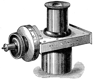
Fig. 167.—The Ramsden Micrometer Eye-piece.
In the Ramsden micrometer eye-piece, as previously explained, two fine wires are stretched across the field of an eye-piece, one of which can be moved by a micrometer screw. In the field there is also a scale with teeth, and the interval between them corresponds to that of the threads of the screw.
The circumference of the brass head is usually divided into one hundred parts, and a screw with one hundred threads to the inch is used. The bacterium to be measured is brought into a position in which an edge appears to be in contact with the fixed wire, and the micrometer screw is turned until the travelling wire appears to be in contact with the other edge. The scale in the field and scale on the milled head, together, give the number of complete turns of the screw and the value of a fraction of a turn in separating the wires.
In the micrometer eye-piece constructed by Zeiss, the eye-piece with a glass plate with crossed lines is carried across the field by means of a micrometer screw. Each division on the edge of a drum corresponds to ·01 mm. Complete revolutions of the drum are counted by means of a figured scale in the visual field.
In the micrometer used with Zeiss’s apochromatic objectives and compensating eye-pieces the divisions are so computed, that, with a tube-length of 160 mm., the value of one interval represents, with each objective, just as many micra (·0001 mm.) as there are millimetres in its focal length. A value of tables is therefore not required for these eye-pieces, since the focus of the lenses indicates their micrometer values within 5 per cent.
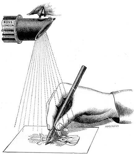
Fig. 168.—The Wollaston Camera Lucida.
The Camera Lucida will prove an extremely useful adjunct to the micrometer, and a large number of contrivances have been devised for its employment. There are those which project the image on to the surface of a sheet of paper provided for the drawing, and those which project the pencil and paper into the field of the microscope. The former method is that usually adopted. To draw an object, with either a Wollaston camera lucida or a neutral tint reflector, such as that of Beale’s, both of which are made to slide on and take the place of the cap of the eye-piece, as shown in Fig. 168, with its flat side uppermost, the whole instrument must be raised until the edge of the prism is exactly 10 inches from a piece of paper placed upon the table; with the latter the instrument retains its vertical position, and the image of the object is thrown on the paper placed in front of the stand. The light must be so regulated that no more than is really necessary is upon the object, whilst a full light should be thrown upon the paper. Only one eye is to be used; and if one half of the pupil be directed over the edge of the prism, the object will appear upon the paper, and can be traced on it by a pencil, the point of which will also be seen. Should any blueness be visible in the field, the prism is pushed too far on, and should be drawn back till the colour disappears.
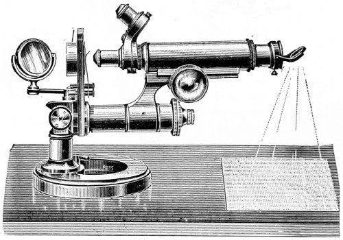
Fig. 169.—Microscope in position for drawing.
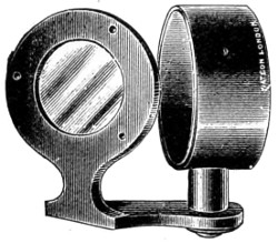
Fig. 170.—Beale’s Neutral Tint Reflector.
The position in which the microscope must be placed is shown in the accompanying illustration (Fig. 169).
Beale’s neutral tint reflector (Fig. 170) is much in use, and its advantages are utility, simplicity, and inexpensiveness.
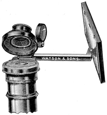
Fig. 171.—The Abbe Model Camera Lucida.
The Abbe model of camera lucida has been brought into use because the projected image can be better illuminated, and is consequently so much brighter. This form is now made in aluminium by Messrs. Watson & Sons. In place of the image being traced by projection on paper, the reverse is the case, both the paper and pencil are projected into the field of view. The mirror reflects the paper on to the silvered surface of a prism placed over the eye-lens of the eye-piece of the microscope, and it is thereby conveyed to the eye. There is a central opening in the silvering through which microscopic vision is obtained. It is fitted in a new manner by means of a cloth-lined adapter, fitting over the outside of the microscope tube; this saves all trouble in centring and ensures concentricity. Where the instrument has capped eye-pieces, the camera lucida must be adapted to the eye-piece, the cap being removed. The apparatus can be disconnected from the fitting adapter by means of a sliding pin, and readily replaced, or can be lifted over out of the way, as shown in the drawing. Being made almost entirely in aluminium it is very much lighter than other forms of apparatus, and does not cause vibration. It can be used with the microscope at any angle, the only necessity being that the paper on which the sketch is made should be kept at the same angle as the instrument.
Micro-Photography.
Micro-photography or photo-micrography, as it is indifferently termed, has, to a very considerable extent, superseded the use of the camera lucida for the delineation of images seen under the microscope. I may claim to be among the first workers with the microscope (1841) to prove beyond a doubt that the camera could be made to render invaluable aid to the microscopist, whereby a great saving of time might be effected, and a drawing obtained with greater accuracy than that of the pencil of the draughtsman.
It was about 1864-5 that Dr. Woodward’s earlier micro-photographs were first seen in London. His skill in the manipulation of the microscope had been long known. His first series of photographs of test diatoms created, I remember, quite a sensation; they have probably never been surpassed. These were taken by sun-light, magnesium, and electric-light. I was the recipient of a series taken at a later date (1870), and which, bound in quarto volume, are almost as perfect in definition as any of a later date taken by oil-immersion objectives.
The objectives used by Dr. Woodward, throughout, were a 1⁄8-inch of Wales’s (new series), and a 1⁄16-inch immersion, of Powell & Lealand’s, especially produced for work with the camera. The magnification varied from 800 to 3,000 diameters, a frustule of Grammatophora Marina magnified 2,500, and a scale of podura, marked 3,000 in my collection, are equal in definition to those taken by a high-angle 1⁄12-inch oil-immersion. Pathological specimens taken with lower powers are equally instructive, a section of epithelial cancer showing both nuclei and cells with distinctness.
Dr. Maddox in 1864 was also experimentally engaged in the improvement of the processes of photography for the purpose of promoting the work of microscopists. His labours were attended with great success. To him we are indebted for the gelatine dry-plate process, which gave a remarkable impetus to photography in general. Dr. Maddox has, for a period extending over forty years, diligently and successfully cultivated and promoted micro-photography. Among other workers to whom we are indebted for improvements in micro-photography I may mention Wenham, Draper, Shadbolt, Highley, Koch, Sternberg, Pringle, Leitz, and Pfeiffer.
Dr. Koch justly claims the credit of having extended the application of micro-photography to the delineation of bacteria. A series of instructive micro-photographs were published by him in 1877.
The importance of the camera has become more manifest as the work of the bacteriologist has progressed. Koch strongly advocated micro-photography on the ground that illustrations, especially of bacteria, should be as true to nature as possible. Dr. Edgar Crookshank holds the same opinion, and in support of his views we have numerous illustrations of the bacteria given in his valuable “Text-book of Bacteriology.” But he does not disguise the truth that there are difficulties to be encountered, the first of which is owing to the fact that the smallest and most interesting bacteria can only be made visible in animal tissues by staining. This drawback has been very nearly overcome by the use of eosin-collodion. With this medium, and by shutting off portions of the spectrum by coloured glasses, Koch succeeded in obtaining photographs of bacteria, which were stained with blue and red aniline dyes. This method, however, introduced a disturbing element of another kind. Owing to the longer exposure required, the results were wanting in definition, attributable, it was thought, to vibrations of the apparatus produced by passing traffic, or by assistants moving about over the floor of the laboratory.
Koch nevertheless showed, at the great meeting of the International Medical Association in London, 1881, a series of micro-photographs of bacteria and tissue sections, which were the admiration of all who saw them. To meet a difficulty occasioned by the aniline dyes, Koch recommended that the preparations should be stained brown; other experimenters found that preparations stained either yellow or yellowish-brown gave good photographic representations; but it is by no means an easy matter to find a good differential stain of bacteria in the tissues, as even Bismarck brown is not entirely successful. Other bacteriologists have encountered similar difficulties at the outset. Hauser succeeded in showing the value of micro-photography in the production of pictures of impression preparations and colonies of bacteria in nutrient-gelatine. But to give the general effect, as well as faithfully reproduce the minute details in these preparations of bacteria by the aid of the pencil, would in most cases create insurmountable difficulties, except in the hand of the most accomplished draughtsman. Hauser employed Gerlach’s apparatus, and Schleusser’s dry-plates, and obtained his illumination by means of a small incandescent lamp, which gave a strong white light. The preparations so photographed were for the most part stained brown, and mounted in the ordinary way in Canada balsam.
In 1884, Van Ermengen succeeded in photographing preparations of comma-bacilli stained with fuchsine and methyl violet. These pictures afforded the first practical illustration of the value of iso-chromatic plates in micro-photography, and their introduction marks a distinct era in the progress of micro-photography. The iso-chromatic, or more properly the ortho-chromatic, dry-plate process was introduced because in photography blue or violet comes out almost or quite white, while other colours, yellow and red, are represented by a sombre shade or even by black. This is due to the want of equality of strength between the luminous and the actinic or chemical rays of light. In other words, the violet and blue rays are more chemically active than any other portion of the spectrum. It was found, then, that if plates were coloured yellow with turmeric, the blue and violet rays were intercepted, and their actinism proportionately reduced.
“In 1881, the so-called iso-chromatic plates were introduced. The emulsion of bromide of silver and gelatine was stained with eosin, and it was claimed that colours could be represented with their relative intensity; chlorophyll and other stains have also been tried, and by such methods the ordinary gelatine dry-plates can be so treated that they will reproduce various colours, according to their relative light intensity, and thus be rendered iso-, or what is now known as ortho-chromatic.”
Apparatus and Material.
Apparatus and Material used in micro-photography have, from time to time, been greatly varied by different workers, some preferring to use the microscope in the vertical position with the camera superimposed or fitted on the eye-piece of the microscope tube; others, again, prefer that both the microscope and the camera should be arrayed horizontally. In another form the ordinary microscope is dispensed with and the objective stage and mirror are adapted to the front of the camera, together with a suitable arrangement for holding the object. Lastly, the camera is lain aside, and an operating-room rendered impervious to light, takes its place, and the image is projected and focussed upon a ground glass screen held in its place by a separate support. This method has been made practical since the introduction into microscopy by Zeiss of the projection eye-piece. It is well known that micro-photographs can be produced by employing these projection eye-pieces, as well as for screen illustrations in the lecture-room.
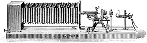
Fig. 172.—Swift’s Horizontal Apparatus.
With regard to the position of the microscope and camera, the horizontal affords greater stability than the vertical, and is on this account to be preferred. The simplest apparatus consists of a camera fixed upon a base board, four or five feet in length, upon which the microscope can be clamped, and which also carries the lamp and bull’s-eye lens (Fig. 172). This arrangement I have found economical and useful. No more elaborate arrangement is actually necessary. Sunlight is no doubt the best, but a good paraffin lamp is a handy and available illuminant.
With the former, and rapid plates, a short exposure of three or four seconds, even when high powers are used, is found sufficient; whereas, with the paraffin lamp it will vary from three to ten minutes.
Walmsley gives the following table for exposures with the lamp:—
1½-inch objective 3 to 45 seconds.
2⁄3-inch " 7 to 90 "
4⁄10-inch " ½ to 3 minutes.
1⁄5-inch " 2 to 7 "
1⁄10-inch " 4 to 10 "
For micro-photography the following practical rules must be observed. The sub-stage condenser may be dispensed with when low powers are used, as well as the mirror, and the lamp so placed that the image of the flat of the flame appears accurately adjusted in the centre of the field of the microscope. The bull’s-eye lens is so interposed, that the image of the flame disappears, and the whole field becomes equally illuminated with high powers; the sub-stage achromatic condenser must be used, and a greater intensity of illumination is obtained by placing the lamp-flame edgeways. It is advisable to begin the practice of micro-photography with low powers, and a trial experiment should be made with some well-known object as the blow-fly’s tongue.
Dr. Crookshank is of opinion that, in the case of micro-organisms when their biological characters are studied under low powers of the microscope, photographs are preferable, because they give a more faithful representation of the object. A micro-organism, even under the highest powers of the microscope, is so minute an object, that to represent it in a drawing requires a very delicate touch, and it is only too easy to make a picture which gives an erroneous impression to those who have not seen the original. Photography enables the scientific worker to record rapid changes, and it is quite possible as the art advances we may find the film more sensitive than the human retina, and that it will bring out details in bacteria which would be otherwise unrecognised. The result, therefore, of experience is that in research laboratories it will come into more general use as a faithful and graphic method. I cannot better bring these observations to a close than by giving a quotation from Dr. Piersoll’s practical method of obtaining micro-photographs.
The three essential conditions to ensure success in micro-photography are:—(1) Satisfactory apparatus; (2) good illumination; (3) suitable preparations. With high amplifications (1,000 diameters and over), the conditions are greatly changed by the approach to the limit both of the shortness of the focus of the objective and of the length of the camera which can be advantageously used; for the first experience leads to the adoption of the 1⁄12-inch, for the second four feet is the limit, since a given high amplification, say 2,000 diameters, can be more satisfactorily and more conveniently obtained with a superior 1⁄12-inch connection with suitable optical means to increase the initial magnifying power of the objective, than with an unaided 1⁄25-inch lens, and the plate removed to a greater distance. Until quite recently the various amplifiers offered the best means of increasing the power of an objective, but the introduction of the projection-oculars of Zeiss is an accessory piece of apparatus, far superior to any older device. These projection-oculars resemble ordinary microscopical oculars or eye-pieces only in general form and name, being optically a projection-objective in connection with a collecting lens. The new oil-immersion apochromatic lenses, in combination with these projection-oculars, form undoubtedly the more efficient equipment for high-power work; it is as true for high-power photography as for microscopical observation in general, that the best results are obtained with fine and necessarily expensive, optical appliances. If for the satisfactory study of the intimate structure of a cell, or of a micro-organism, the most improved immersion lenses are necessary, it is to be expected that, for the successful photography of the same, tools at least as good are needed. Sunlight certainly affords the most satisfactory illumination whereby good micro-photographs can be obtained, as well as for recording microscopical images. That by good lamp-light fair impressions of objects under extreme magnification can be secured is encouraging, but the negatives produced by such illumination seldom, if ever, possess the characteristics of a really good sunlight negative, where the sharpest details are combined with an exquisite softness and harmony of half-tones.
If the mirror of the microscope be of good size, it will only be necessary to make an arm on which to support the removed mirror outside some southerly exposed window, since it is desirable to have a greater distance between the mirror and the stage than would be possible were the mirror attached in its usual place. Where the microscope mirror is too small to be satisfactorily used, a rectangular wood-framed looking-glass is readily mounted, with the aid of a few strips of wood, so as to turn about both axes.
The rays from the plane side of the mirror should pass through a condensing lens (of 8-10-inch focus, if possible), so placed that they are brought to a focus before reaching the plane of the object. The exact position of the condensing lens is a matter of experience; usually, however, the most favourable illumination is obtained at that point where the field is brilliantly and uniformly illuminated, just before the rays form the image source of light; the nearer the focus the less disturbance from diffraction rings. Ordinary objectives will require the employment of monochromatic light—produced either by a deep blue solution of ammonia-sulphate of copper, or by the green glass screen—since the optical and actinic foci do not usually perfectly coincide. Powers up to the ¾-inch will require no further condenser; with the ¼ or 1⁄6-inch objectives, the low power (1 or ¾-inch) serves with advantage as an achromatic condenser, when attached to the sub-stage. The Abbe condenser, although so important for fine microscopical investigation, is not adapted to photography unless a very wide cone of light is desired, which, for the majority of preparations, is some advantage; a low-power objective, used as a condenser, is found to be more satisfactory than the Abbe with a small diaphragm.30
The greatest delicacy in manipulation is necessary, as in working with a 1⁄12-inch objective a turn too much of the fine adjustment will cause the image to vanish. With fine preparations of bacteria it is not easy to trace the image, and hence the advantage of commencing with a well-marked object, as that of the fly’s tongue. The development and fixation of the image must be proceeded with as in the ordinary photographic process. In the text-books of photography full accounts of failures will be found, their causes and prevention. Numerous papers and suggestions for micro-photographic work will also be found scattered throughout the “Journal of the Royal Microscopical Society.”
The Projection Eye-piece has become an essential part of micro-photography, and it is so arranged that it may be employed with advantage with objectives of either the apochromatic or ordinary series for photographic purposes, projecting an exquisitely sharp image of the object on the plate. A diaphragm between the lenses limits the field, and a sharp image of it should appear on the screen when the eye-piece is adjusted. The adjustment may be effected by revolving the eye-piece cap in a spiral slot, so that the eye or top lens is either brought closer or removed farther away from the diaphragm, as may be required, and divisions and a reader are usually provided for registering positions. Such eye-pieces are made to fit any size microscope body.
Initial magnifying powers:—
English length of tube 10-in. 3 and 6.
Continental "" 6-in. 2 and 4.
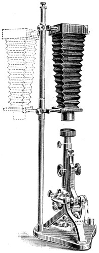
Fig. 173.—Baker’s Pringle Vertical Micro-photographic Apparatus.
The microscope and camera (Fig. 173) are here seen to be part of the same instrument. The bellows of the camera have an extension varying from 6 in. to 30 in. The board on which the microscope and limelight jet are fixed is made to turn out of the line of the camera to facilitate adjusting the instrument and radiant, either limelight, electric light or paraffin lamp; when this is done the board carrying the same is turned back to a stop which brings the microscope into a central position with the focussing screen. An adjustment is supplied at the side of the camera, geared to the slow movement, for finely focussing the object upon the screen. A light-excluding connection is fitted to the front of the camera and microscope; immediately behind this, in the bellows, is an exposing shutter which is manipulated by means of a small milled head. Two focussing screens are usually supplied, one grey, and one patent plate, together with a double dark slide.
Mr. Andrew Pringle’s vertical micro-photographic apparatus is an excellent form; it consists of a heavy base and brass support, carrying a quarter-plate camera, grey and plain glass focussing screen, double dark back, camera extending to 24 inches, and turning aside as shown in Fig 173. It is light-tight in all its connections.
To secure uniform results in micro-photography, only thin preparations, which lie as nearly as possible in one plane, can be relied upon for good and perfect negatives.
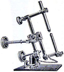
Fig. 174.—Ross’s Arc Lamp.
An electric arc lamp specially designed for micro-photographic work, wherever the electric current is available, is that known as “the Ross-Hepworth projection arc lamp.” The advantage gained by this form of lamp is not only on account of the ease with which it may be employed, but also on account of its superior power and quality. It is of primary importance that the lamp employed to convert the electricity into light should be of a good and reliable pattern. It is not essential that it should be automatic in its working—many experienced micro-photographers preferring a simple hand-feed lamp to the one of a more complicated kind, being so much less difficult to keep in order. A good hand-feed microscope-lamp has the advantage of greater simplicity and portability.
The argand gas-light arranged for me many years ago for micro-photography may be employed with advantage. It is clean, and always ready for use when brought down to the table attached by a piece of india-rubber tubing. The incandescent form of burner enhances its value, since the light is thereby rendered whiter. The arrangement is shown in the diagrammatic drawing, Fig. 175.
Over the argand burner B, is a pale-blue glass chimney, resting on a wire gauze, stage A; this secures a uniform current of air. The colour of the flame may be still more influenced by a disc of neutral tint, or other coloured glass, inserted into the circular opening at E, in a half-cylinder of metal, G, used to cut off all extraneous light; can be rotated on the stage by the ivory nob at H, a metallic reflector I, attached to the standard rod, on being brought parallel to F serves to concentrate the light and send it on to the bull’s-eye, and through it to the mirror, or directly to the photo-microscopic camera.
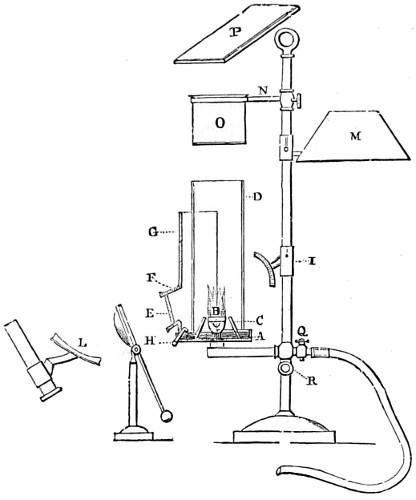
Fig. 175.—Table Incandescent Gas-lamp.
By removing the shield G, and bringing the shade M over the burner, it is at once converted into a useful microscopical lamp, for all ordinary purposes. The screw R clamps the lamp-flame at any height, while the support N carries a water-bath O, or a plate P, both of which will be found useful in preparing and mounting objects.
A special incandescent gas-lamp is made by Messrs. R. & J. Beck.
Polarisation of Light.
Common light moves in two planes at right angles to each other, while polarised light moves in one plane only. Common light may be turned into polarised light either by transmission or reflection; in the first instance, one of the planes of common light is got rid of by reflection; in the other, by absorption. Huyghens was one of the first physicists to notice that a ray of light has not the same properties in every part of its circumference, and he compared it to a magnet or a collection of magnets; and supposed that the minute particles of which it was said to be composed had different poles, which, when acted on in certain ways, arranged themselves in particular positions; and thence the term polarisation, a term having neither reference to cause nor effect. It is to Malus, however, who, in 1808, discovered polarisation by reflection, that we are indebted for the series of splendid phenomena which have since that period been developed; phenomena of such surpassing beauty as to exceed most ordinary objects presented to the eye under the microscope.
Certainly no more misleading name could well have been found to describe the causation, in one particular direction, of small displacements in the medium, through which the light waves are made to pass.
The effect of “polarising” light is simply to alter the directions of the vibrations of light, and allow of certain waves to pass which are vibrating in one direction only, vertical, horizontal, or oblique, as the case may be. The most efficient agent discovered for the polarisation of light is that of Iceland spar, cut and mounted as a “Nicol” prism.
By cutting crystals of Iceland spar into two parts, at a particular angle, and cementing them together again in the reverse way, Nicol succeeded in showing that one of the two polarising pencils could be totally deflected to one side, while the other is directly transmitted through the Nicol prism, and thereby the beam of light becomes at once “polarised” in one plane only. No apparent difference can be seen in the prism on holding it up to the light, except it be in a very slight loss of brightness; but if another similarly heated crystal be held before, and made to revolve around, a quarter of the circle just where the two cross each other, total darkness results. This phenomenon alternately recurs at every quadrature of the circle. A pair of Nicol prisms, when appropriately mounted, constitute “a polarising apparatus” for the microscope, one being fitted into the sub-stage, and the other either immediately above the objective or eye-piece, where it can be easily rotated, the object to be examined being placed on the stage of the microscope, that is, between the polarising and analysing prisms.
Polariscope Objects.
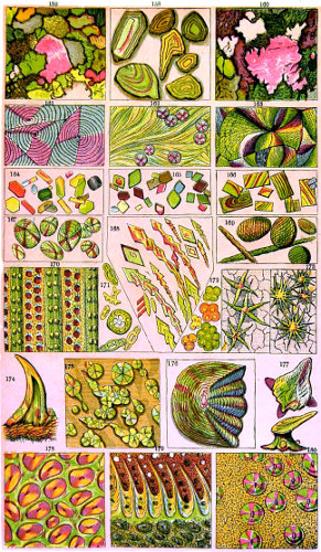
Tuffen West, del. Edmund Evans.
Plate VIII.
The significance of polarised light centres in the fact that it affords a wider insight into the structure of crystals, minerals, and a number of other substances, and which could not otherwise be obtained without its aid. Its usefulness is multifold, as even glass itself, when not properly annealed, exhibits points of fracture, by a display of Newton’s rings. The knowledge thus acquired is turned to account by glass manufacturers.
Double refraction.—When an incident ray of light is refracted into a crystal of any other than the cubic system, or into compressed or unannealed glass, it gives rise to two refracted rays which take different paths; this phenomenon is termed double refraction. Attention was called to this in 1670, by Bartolin, who first observed it in Iceland spar; and the laws for this substance were accurately determined by Huyghens.
Iceland spar or calc spar is a form of crystallized carbonate of lime. It is composed of fifty-six parts of lime and forty-four parts of carbonic acid, and is usually found in rhombohedral forms of crystallization.
To observe the phenomenon of double refraction, a rhomb of Iceland spar may be laid on a page of a printed book, when all the letters seen through it will appear double; the depth of the blackness of the letters is seen to be considerably less than that of the originals, except where the two images overlap.
In order to state the laws of the phenomena with precision, it is necessary to attend to the crystalline form of Iceland spar, which has equal obtuse angles. If a line be drawn through one of these corners, making equal angles with the three edges which meet there, it, or any line parallel to it, is called the axis of the crystal; the axis being, properly speaking, not a definite line but a definite direction.
The angles of the crystals are the same in all specimens. If the crystal is of such proportions that these three edges spoken of are equal, as in the smaller crystal (Fig. 176), the axis is the direction of one of its diagonals, as represented.
Any plane containing (or parallel to) the axis is called the principal plane of the crystal.
In the next diagram, Fig. 177, the line appears double, as a b and c d, or the dot, as e and f. Or allow a ray of light, g h, to fall thus on the crystal, it will in its passage through be separated into two rays, h f, h e; and on coming to the opposite surface of the crystal, will pass out at e f in the direction of i k, parallel to g h. The plane l m n o is designated the principal section of the crystal, and the line drawn from the solid angle l to the angle o is where the axis of the crystal will be found; this is its optic axis. Now when a ray of light passes along this axis, it is undivided, and there is only one image; but in all other directions there are two images.
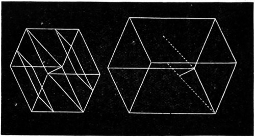
Fig. 176.—Axis of Crystals of Iceland Spar.
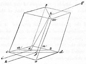
Fig. 177.—A Rhomb showing the passage of Rays of Light.
Mr. Nicol, of Edinburgh first succeeded in making a rhomb of Iceland spar into a single-image prism. His method of splitting up the crystal into two equal parts was as follows:—
A rhomb of Iceland spar of one-fourth of an inch in length, and about four-eighths of an inch in breadth and thickness, is divided into two equal portions in a plane, passing through the acute lateral angle, and nearly touching the obtuse side angle. The sectional plane of each of these halves must be carefully polished, and the two portions cemented firmly together with Canada balsam, so as to form a rhomb similar to that before division; by this management the ordinary and extraordinary rays are so separated that only one is transmitted: the cause of this great divergence of the rays is considered to be owing to the action of the Canada balsam, the refractive index of which (1·549) is that between the ordinary (1·6543) and the extraordinary (1·4833) refraction of calcareous spar, and which will change the direction of both rays in an opposite manner before they enter the posterior half of the combination. The direction of rays passing through such a prism is indicated by the arrow, Fig. 178.
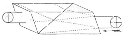
Fig. 178.
Polarised light cannot be distinguished from common light, as already said, by the naked eye; and for all experimental purposes in polarisation, two pieces of apparatus must be employed, one to produce polarisation, and the other to show or an analyse it. The former is called the polariser, the latter the analyser; and every apparatus that serves for one of these purposes will also serve for the other.
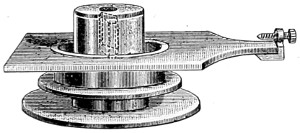
Fig. 179.—Polariser.
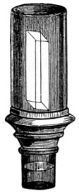
Fig. 179a.—Analyser.
Polarising Apparatus for Students’ Microscope.
In all cases there are two positions, differing by 180°, which give a minimum of light, and the two positions intermediate between these give a maximum of light. The extent of the changes thus observed is a measure of the completeness of the polarisation of light.
The two prisms mounted as shown in Figs. 179 and 179a constitute the apparatus adapted to the microscope. The polariser slips into place below the stage, and the analyser, with the prism fixed in a tube, is screwed in above the objective.
The definition is considered by some experimenters as somewhat better if the analyser be used above the eye-piece, and is certainly more easily rotated.
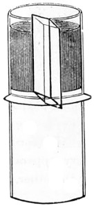
Fig. 180.—Prism mounted as an Eye-piece.
Method of employing the Polarising Prism (Fig. 179).—After having adapted it to slide into a groove on the under-surface of the stage, where it is secured and kept in place by the small milled-head screw, the other prism Fig. 179a) is screwed on above the object-glass, and thus passes directly into the body of the microscope. The light from the mirror having been reflected through them the axes of the two prisms must be made to coincide; this is done by regulating the milled-head screw until, by revolving the polarising prism, the field of view is entirely darkened twice during its revolution. If very minute salts or crystals are submitted for examination then it will be found preferable to place the analyser above the eye-piece, as in Fig. 180. Thus the polariscope is seen to consist of two parts; one for polarising, the other for analysing or testing the light. There is no essential difference between the two parts, except what convenience or economy may lead us to adopt; and either part, therefore, may be used as polariser or analyser; but whichever is used as the polariser, the other becomes the analyser.
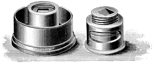
Fig. 181.—More Modern Polariser and Analyser.
Opticians have their own methods of adapting the polariser and analyser to their several microscopes. Watson’s special form of apparatus is represented in Fig. 181, the polariser being adapted to the sub-stage, and the analyser to screw into the objective.
Tourmaline.—A semi-transparent mineral, of a neutral or bluish tint, called tourmaline, when cut into thin slices (about 1⁄20-inch thick) with their faces parallel to their axes exhibit the same phenomena as the Nicol prism. The only objection to which is that the transmitted polarised beam is more or less coloured. The tourmaline to be preferred stops the most light when its axis is at right-angles to that of the polariser, and yet admits the most when in the same plane. Make choice of a tourmaline as perfect as possible; size is of less importance when intended for use with the microscope.
Transmission of rays through tourmaline is only one of several ways in which light can be polarised. When a beam of light is reflected from a polished surface of glass, wood, ivory, leather, or any other non-metallic substance, at an angle of 50° to 60° with the normal, it is more or less polarised, and in like manner a reflector composed of any of these substances may be employed as an analyser. In so using it, it should be rotated about an axis parallel to the incident rays which are to be tested, and the observation consists in noting whether this rotation produces changes in the amount of reflected light.
For every reflected substance there is a particular angle of incidence, which gives a maximum of polarisation in reflected light. It is called the polarising angle for the substance, and its tangent is always equal to the index of refraction of the substance; or, what amounts to the same thing, it is that particular angle of incidence which is the complement of the angle of refraction, so that the refracted rays are at right angles. This important law was discovered experimentally by Sir David Brewster.
Tourmaline, like Iceland spar, is a negative uniaxial crystal; and its use as a polariser depends on the property which it possesses of absorbing the ordinary much more rapidly than the extraordinary ray, so that a thickness which is tolerably transparent to the latter is almost completely opaque to the former. Its pale cobalt blue colour enhances the beauty of certain crystal and mineral substances, but like Iceland spar, the paler and more perfect crystals are becoming scarce.
Selenite is another mineral of value in polarisation experiments. It is a native crystalline hydrated sulphate of lime. A beautiful fibrous variety called satin-gypsum is found in Derbyshire. The form of the crystal most frequently met with is that of an oblique rectangular prism, with ten rhomboidal faces, two of which are much larger than the rest. It is usually split up into thin laminæ parallel to their lateral faces; each film should have a thickness of from one-twentieth to one-sixtieth of an inch. In the two rectangular directions these films allow perpendicular rays of polarised light to traverse them unchanged, termed their neutral axes. In two other directions, however, which form respectively angles of 45° with the neutral axes, these films have the property of double refraction, a direction known as the depolarising axis.
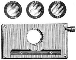
Fig. 182.—Darker’s Selenite Films and Stage.
The thickness of the film of selenite determines the particular tint. If, therefore, we use a film of irregular thickness, different colours are presented by the different thicknesses. These facts admit of very curious and beautiful illustration, when used under the object placed on the stage of the microscope. The films employed should be mounted between two glasses for protection. Some persons employ a large film, mounted in this way between the plates of glass, with a raised edge, to act as a stage for supporting the object, it is then called the “selenite stage.” The best film for the microscope is that which gives blue, and its complementary colour yellow. The late Mr. Darker constructed a selenite stage for the purpose (Fig. 182). With this a mixture of colours will be brought about, by superimposing three films, one on the other. By slight variations in their positions, produced by means of an endless-screw motion, all the colours of the spectrum can be shown. When objects are thus exhibited, it should be borne in mind that all negative tints, as they are termed, are diminished, and all positive tints increased; the effect of which is to mask the true character of the phenomena.
For a certain thickness of selenite the ellipse will become a circle, and we have thus what is called circularly-polarised light, which is characterised by the property that rotation of the analyser produces no change of intensity. Circularly-polarised light is not, however, identical with ordinary light; for the interposition of an additional thickness of selenite converts it into elliptically (or in a particular case into plane) polarised light.
It is necessary, for the exhibition of colour in our experiments, that the plate of selenite should be very thin, otherwise the retardation of one component vibration as compared with the other will be greater by several complete periods for violet than for red, so that the ellipses will be identical for several different colours, and the total non-suppressed light will be sensibly white in all positions of the analyser.
Two thick plates may, however, be so combined as to produce the effect of one thin plate. For example, two selenite plates of nearly equal thickness may be laid one upon the other, so that the direction of greatest elasticity in the one shall be parallel to that of least elasticity in the other. The resultant effect in this case will be that due to the difference of their thicknesses. Two plates so laid are said to be crossed.
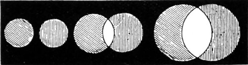
Fig. 183.—Red is represented by perpendicular lines; Green by oblique.
The following experiments will well serve to illustrate some of the more striking phenomena of double refraction, and will also be a useful introduction to its practical application. Take a plate of brass (Fig. 183) three inches by one, perforated with a series of holes from about one-sixteenth to one-fourth of an inch in diameter; the size of the smallest should be in accordance with the power of the objective, and the separating power of the double refraction.
Experiment 1.—Place the brass plate so that the smallest hole shall be in the centre of the stage of the microscope; employ a low power (1½ or 2 inches) objective, and adjust the focus as for the ordinary microscopic object; place the double image prism over the eye-piece, and two distinct images will be seen; by revolving the prism, the images will describe a circle, the circumference of which will cut the centre of the field of view; one of which is the ordinary, the other the extraordinary ray. By moving the slide from left to right the larger orifices will appear in the field, the images seen will not be completely separated, but will overlap, as represented in the figure.
Experiment 2.—Insert the Nicol’s prism into its place under the stage, still retaining the double image prism over the eye-piece; then, by examining the object, there will appear in some positions two images, in others only one image; it will be seen, that at 90° this ray will be cut off, and that which was first observed will become visible; at 180°, or one-half the circle, an alternate change will take place; at 270°, another change; and at 360°, the completion of the circle, the first image will reappear.
Before proceeding to make the next experiment, the position of the Nicol’s prism should be adjusted, and its angles brought parallel with the square of the stage. The true relative position of the selenite should also be determined by noticing the natural flaws in the film, which should run parallel with each other, and be adjusted at an angle of about 46° with the square bars of the stage.
Experiment 3.—If we now take the plate of selenite thus prepared, and place it under the piece of brass on the stage, we shall see, instead of the alternate black and white images, two coloured images composed of the constituents of white light, which will alternately change by revolving the eye-piece at every quarter of the circle; then, by passing along the brass, the images will overlap; and at the point at which they do so, white light will be produced. If, by accident, the prism be placed at an angle of 45° from the square part of the stage, no particular colour will be perceived, and it will then illustrate the phenomena of the neutral axis of the selenite, because when placed in the relative position no depolarisation takes place. The phenomena of polarised light may be further illustrated by the addition of a second double image prism, and a film of selenite adapted between the two. The systems of coloured rings in crystals cut perpendicularly to the principal axis of the crystal are best seen by employing the lowest object-glass.
Biaxial Crystals.—To show perfectly the beautiful series of rings and brushes which biaxial crystals exhibit, it becomes necessary to convert the microscope, for the time being, into (so to speak) a wide-angled telescope.
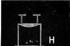
Huyghenian Eye-piece.
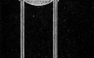
Inner draw-tube.
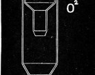
Objective in draw-tube.
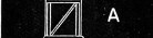
Analysing Prism.
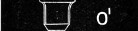
Objective.

Specimen under Examination.
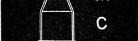
Sub-stage Condenser.
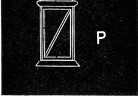
Polarising Prism, fixed in sub-stage below.
Fig. 184.—Diagrammatic arrangement of the Polarising Microscope.
In Sub-stage: P, polarising prism; C, sub-stage condenser on stage; M, mineral or crystal. On nose-piece: O1, objective, 4⁄10-inch; A, analysing prism.
In Draw-tube: O2, 2 or 3 inch Objective; H, Huyghenian eye-piece.
For the purpose, screw on a low-power objective to the end of the draw-tube (Fig. 184).31 As the light requires to be passed through the crystals at a considerable angle, a wide-angled condenser should be employed, but it need not be achromatic. The objective most suitable is a 4⁄10-inch, of ·64 numerical aperture, but a ¼-inch of ·71 numerical aperture, or a 1⁄3-inch of ·65 numerical aperture, will answer the purpose equally well. As the whole of the back lens of the objective should be visible through the analysing Nicol prism, the back lens of the objective must not be too large; thus a ½-inch of ·65 numerical aperture will not be so effective. The analysing prism may be placed either where it is in the drawing, below the stage, or above the eye-piece. It works equally well above the objective, the position it ordinarily occupies in the microscope.
For the draw-tube a 2-inch objective and a B Huyghenian eye-piece answers very well. Before screwing the objective on to the end of the draw-tube centre the light in the usual manner, the Nicol’s being turned so as to give a light field, then screw the objective on to the end of the aperture, and put the crystal on the stage, rack down the body so that the objective on the nose-piece nearly touches the crystal, then focus with the draw-tube only. The sub-stage condenser should be racked up close to the underside of the crystal.
Opticians, however, have more recently furnished a special form of microscope (The Petrological Microscope, Fig. 79, p. 112), for the use of those students who may desire to prosecute so fascinating a study, and determine the optic axial angles of crystals.
Fuess32 lately introduced a new form of microscope for polarising and viewing biaxial crystals, which he believes to be needed, as in the ordinary microscope the opening of the polariser is scarcely a third of that of the condenser; moreover, it is not absolutely necessary that the polariser and analyser should be Nicol’s prisms. This fact was discovered by myself many years ago. Fuess utilises a bundle of thin glass plates, as in the older Nuremberg polariscope. The frame holding plates can be readily adjusted at the proper polarising angle, the analyser being the ordinary small Nicol, screwed above the objective. The illuminator is an Abbe’s triple condenser, of numerical aperture 1·40, which can be adjusted in the ordinary way. The front lens of this should have a diameter of 11·12 mm. and the lower lens of 30 mm. This increase in the condenser fully compensates for the loss of light by the bundle of glass plates, and also enables thick sections of crystals to be examined in convergent polarised light. The ocular used should have a large field; the A Huyghenian answers best. A suggestion to return to the original Nuremberg polariser is very opportune, as Iceland spar is becoming scarce.
Mr. A. Mickel accidentally discovered that an opalescent mirror can be converted into an excellent and inexpensive substitute for the Nicol-prism polariser.
Rotation of Plane of Polarisation.
When a plate of quartz (rock-crystal), even of considerable thickness, cut perpendicular to the axis, is interposed between the polariser and analyser, colour is exhibited, the tints changing as the analyser is rotated; and similar effects of colour are produced by employing, instead of quartz, a solution of sugar enclosed in a tube with plain glass ends.
The action thus exerted by quartz and sugar is called rotation of the plane of polarisation, a name which sufficiently expresses the observed phenomena. In the case of ordinary quartz, and solutions of sugar-candy, it is necessary to rotate the analyser in the direction of watch-hands as seen by the observer, and the rotation of the plane of polarisation is said to be right-handed. In the case of what is called left-handed quartz, and of solutions of non-crystallisable sugar, the rotation of the plane of polarisation is in the opposite direction, and the observer must rotate the analyser against watch-hands.
Quartz belongs to the uniaxial system of crystals, and accordingly exhibits one series of rings only, and no perfect central black cross.
On revolving the tourmaline the colour gradually changes, and passes through all the colours of the spectrum. It can be cut to exhibit either right-handed polarisation or left-handed polarisation and also to exhibit straight lines.
Calc Spar.—A uniaxial crystal showing only one system of rings, and a black cross, changing into a white cross on revolving the tourmaline.
Topaz.—A biaxial crystal exhibiting only one system of rings with one fringe, owing to the wide separation of the axes. The fringe and colours change on revolving the tourmaline.
Borax.—A biaxial crystal; the colours are seen to be more intense than in topaz, but the rings not so complete—only one set of rings can be seen, owing to their wide separation.
Rochelle Salt.—A biaxial crystal; the colours are more widely spread out than the former, and only one set of rings seen at the same time.
Carbonate of Lead.—A biaxial crystal; axes not so far separated, and both systems of rings are more widely spread than those of potassium nitrate.
Aragonite.—A biaxial crystal; axes widely separated, but both systems of rings seen at the same time. A fine crystal for displaying the biaxial system.
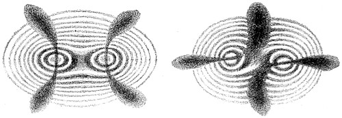
Fig. 185.—Crystal of Potassium Nitrate.
It was long believed that all crystals had only one axis of double refraction; but Brewster found that the greater number of crystals which occur in the mineral kingdom have two axes of double refraction, or rather axes around which double refraction takes place; in the axes themselves there is no double refraction.
Potassium nitrate crystallises in six-sided prisms with angles of about 120°. It has two axes of double refraction. These axes are each inclined about 2½° to the axes of the prism, and 5° to each other. If, therefore, a small piece be split off a prism of potassium nitrate with a knife driven by a sharp blow of a hammer, and the two surfaces polished perpendicular to the axes of the prism, so as to leave the thickness of the sixth or eighth of an inch, and then a ray of polarised light be transmitted along the axes of the prism, the double system of rings will be clearly visible.
When the line connecting the two axes of the crystal is inclined 45° to the plane of primitive polarisation, a cross is seen on revolving the potassium nitrate; it gradually assumes the form of two hyperbolic curves, as in Fig. 185. But if the tourmaline be again revolved through half a quadrant, the black cross will be replaced by white spaces, as in the second figure. These systems of rings have, generally speaking, the same colours as those of thin plates, or as those of a system of rings revolving around one axis. The orders of the colours commence at the centres of each system; but at a certain distance, which corresponds to the sixth ring, the rings, instead of returning and encircling each pole, encircle the two poles as an ellipse does its two foci. If the thickness of the plate of nitre be diminished or increased, the rings are diminished or increased according to the thickness of the crystal.
Small specimens of various salts may be crystallised and mounted in Canada balsam for viewing under the stage of the microscope; by arresting crystallisation at certain stages, a greater variety of forms and colours will be obtained: we may enumerate salicine, asparagine, acetate of copper, phospho-borate of soda, sugar, carbonate of lime, potassium chlorate, oxalic acid, and all the oxalates found in urine, with the other salts from the same fluid, a few of which are shown in Plate VIII.
The late Dr. Herapath described a salt of quinine, remarkable for its polarising properties. The crystals of this salt, when examined by reflected light, have a brilliant emerald-green colour, with almost a metallic lustre; they appear like portions of the elytræ of the cantharides beetle, and are also very similar to murexide in appearance. When examined by transmitted light, they scarcely possess any colour, there is only a slightly olive-green tinge; but if two crystals, crossing at right-angles, be examined, the spot where they intersect appears perfectly black, even if the crystals are not more than one five-hundredth of an inch in thickness. If the light be in the slightest degree polarised—as by reflection from a cloud, or by the blue sky, or from the glass surface of the mirror of the microscope placed at the polarising angle 65° 45′—these little prisms and films assume complementary colours: one appears green, and the other pink, and the part at which they cross is chocolate or deep chestnut-brown, instead of black. Dr. Herapath succeeded in making artificial tourmalines large enough to surmount the eye-piece of the microscope; so that all experiments with those crystals upon polarised light may be made without the tourmaline or Nicol’s prism. The finest rosette crystals are made as follows:—To a moderately strong solution of Cinchonidine add a drop or two of Herapath’s test-fluid.33 A few drops of this is placed on the centre of a glass slide, and put aside until the first crystals are observed to be formed near the margin. The slide should now be placed upon the stage of the microscope, and the progress of formation of the crystals closely watched. When these are seen to be large enough, and it is deemed necessary to stop their further development, the slide must be quickly transferred to the palm of the hand, the warmth of which will be found sufficient to stop further crystallisation. These crystals attract moisture, deliquesce, and should therefore be kept in a perfectly dry place.
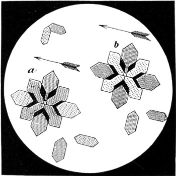
Fig. 186.—In this figure heraldic lines are adopted to denote colour. The dotted parts indicate yellow, the straight lines red, the horizontal lines blue, and the diagonal, or oblique lines, green. The arrows show the plane of the tourmaline, a, blue stage; b, red stage of selenite employed.
To render these crystals evident, it merely remains to bring the glass-slide upon the field of the microscope, with the selenite stage and single tourmaline, or Nicol’s prism, beneath it; instantly the crystals assume the two complementary colours of the stage: red and green, supposing that the pink stage is employed; or blue and yellow, provided the blue selenite is made use of. All those crystals at right angles to the plane of the tourmaline produce that tint which an analysing-plate of tourmaline would produce when at right angles to the polarising-plate; whilst those at 90° to these educe the complementary tint, as the analysing-plate would also have done if revolved through an arc of 90°.
This test is a delicate one for quinine (Fig. 186, a and b); not only do these peculiar crystals act in the way just related, but they may be easily proved to possess the optical properties of that remarkable salt, the sulphate of iodo-quinine.
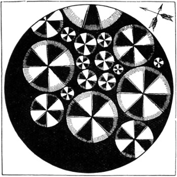
Fig. 187.—Polarised Crystals of Quinidine.
To test for quinidine, it is merely necessary to allow a drop of acid solution to evaporate to dryness upon the slide, and to examine the crystalline mass by two tourmalines, crossed at right angles, and without the stage. Immediately little circular discs of white, with a well-defined black cross, start into existence, should quinidine be present even in very minute traces. These crystals are represented in Fig. 187.
If the selenite stage be employed in the examination of this object, one of the most gorgeous appearances in the whole domain of the polarising microscope is displayed: the black cross disappears, and is replaced by one consisting of two colours, and divided into a cross having a red and green fringe, whilst the four intermediate sectors are a gorgeous orange-yellow. These appearances alter on the revolution of the analysing-plate of tourmaline; when the blue stage is employed, the cross assumes a blue or yellow tint, varying according to the position of the analysing plate. These phenomena are analogous to those exhibited by certain circular crystals of boracic acid, and to circular discs of salicine (prepared by fusion), the difference being that the salts of quinidine have more intense depolarising powers than either of the other substances; the mode of preparation, however, excludes these from consideration. Quinine prepared in the same manner as quinidine has a very different mode of crystallisation; but it occasionally presents circular corneous plates, also exhibiting the black cross and white sectors, but not with one-tenth part of the brilliancy, which of course enables us readily to discriminate the two.
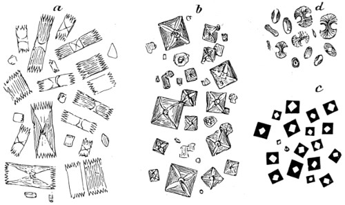
Fig. 188.—Urinary Salts, seen under Polarised Light.
a, Uric acid; b, Oxalate of lime, octahedral crystals of; c, Oxalate of lime allowed to dry, forming a black cube; d, Oxalate of lime as it occasionally appears, termed the dumb-bell crystal.
Urinary salts are more readily seen under polarised light than by white light. Ice doubly refracts, while water singly refracts. Ice takes the rhomboidic form; and snow in its crystalline forms may be regarded as the skeleton crystals of this system (Fig. 189). A sheet of clear ice, of about one inch thick, and slowly formed in still weather, shows circular rings with a cross by polarised light.
Fig. 189.—Snow Crystals.
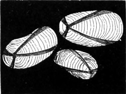
Fig. 190.—Potato Starch, under Polarised Light.
It is probable that the conditions of snow formation are more complex than might be imagined, familiar as we are with the conditions relating to the crystallisation of water on the earth’s surface. A great variety of animal, vegetable, and other substances possess a doubly refracting or depolarising structure, as: a quill cut and laid out flat on glass; the cornea of a sheep’s eye; skin, hair, a thin section of a finger-nail; sections of bone, teeth, horn, silk, cotton, whalebone; stems of plants containing silica or flint; barley, wheat, &c. The larger-grained starches form splendid objects; tous-les-mois, the largest, may be taken as a type of all others. This presents a black cross, the arms of which meet at the hilum (Fig. 190). On rotating the analyser, the black cross disappears, and at 90° is replaced by a white cross; another, but much fainter, black cross is seen between the arms of the white cross, no colour being perceptible. But if a thin plate of selenite be interposed between the starch-grains and the polariser, a series of delicate colours appear, all of which change on revolving the analyser, becoming complementary at every quadrant of the circle. West and East India arrow-root, sago, tapioca, and many other starch-grains, present a similar appearance; but in proportion as the grains are smaller, so are their markings and colourings less distinct.
Molecular Rotation.
For the purpose of studying the various interesting phenomena of molecular rotation, a few necessary pieces of apparatus must be added to the microscope. First, an ordinary iron three-armed retort stand, to the lower arm of which must be attached either a polarising prism or a bundle of glass plates inclined at the polarising angle; in the upper an analysing prism. The fluid to be examined should be contained in a narrow glass tube about eight inches in height, and this must be attached to the middle arm. If the prisms be crossed before inserting a fluid possessing rotatory power, the light passing through the analyser will be coloured. If a solution of sugar be employed, and the light which passes through the second prism is seen to be red, but on rotating the analyser towards the right the colour changes to yellow, and passes through green to violet, it may be concluded that the rotation is right-handed. If, on the contrary, the analyser requires to be turned towards the left hand, we conclude that the polarisation is left-handed. These phenomena are wholly distinct from those accompanying the action of doubly refracting substances upon plane polarised light. It is not easy to explain in a limited space the course to be followed in ascertaining the amount of rotation produced by different substances. Monochromatic light should be used. If we are about to examine a sugar solution with the prisms crossed, the index attached to the analyser must first be made to point to zero. The sugar is then introduced, when it will be necessary to rotate the analyser 23° to the right, in order that the light may be extinguished. This is the amount of rotation for that particular fluid at a given density and that height of column. As the arc varies with increase or decrease of density and height of the fluid, it is needful to reduce it to a unit of height and density. The following formula is that given by Biot:—P = quantity of matter in a unit of solution; d = sp. gr.; l = length of column; a = arc of rotation; m = molecular rotation.
Then m = a/(l p d).
The application of the polarising apparatus to the microscope is of much value in determining minute structure. It may also be defined as an instrument of analysis; a test of difference in density between any two or more parts of the same substance. All structures, therefore, belonging either to the animal, vegetable, or mineral kingdom, in which the power of unequal or double refraction is suspected to be present, are those that should especially be re-investigated by polarised light. Some of the most delicate of the elementary tissues of animal structure, the ultimate fibrillæ of muscles, &c., are amongst the most interesting subjects that might be studied with advantage under this method of investigation. The chemist may perform the most dexterous analysis; the crystallographer may examine crystals by the nicest determination of their forms and cleavage; the anatomist or botanist may use the dissecting knife and microscope with the most exquisite skill; but there are still structures in the mineral, vegetable, and animal kingdoms which will defy all such modes of examination, and will yield only to the magical analysis of polarised light.
Formation and Polarisation of Crystals.
The inorganic kingdom will afford to the microscopist a never-ending number of objects of unsurpassed beauty and interest. The phenomena of crystallisation in its varied combinations can be made a useful and instructive occupation. Although ignorant of the means whereby the great majority of minerals and crystals have been formed in the vast laboratory of Nature, we can, nevertheless, imitate in a small degree Nature’s handiworks by crystallising out a large number of substances, and watch their numerous transformations in the smallest appreciable quantities, when aided by the microscope.
Among natural crystals we look for the material for the formation of our lenses, while the varieties of granites present us with the earliest crystallised condition of the earth’s crust as it cooled down, the structure of which is beautifully exhibited under polarised light. In Plate VIII. various crystalline and other bodies are displayed. In No. 158 is a section of new red sandstone; 159 of quartz; and 160 of granite. Special reference is made to others in the following list of salts and other substances which form a beautiful series of objects for study under polarised light:—
SALTS.
Alum. Asparagine. Aspartic Acid. Plate VIII. No. 168. Bitartrate of Ammonia. Boracic Acid. Borax. No. 164. Carbonate of Lime. " Soda. Chlorate of Potash. Chloride of Barium. " Cobalt. " Copper and Ammonia. " Sodium. Cholesterine. Chromate of Potash. Cinchonine. Cinchonidine. Citric Acid. Hippuric Acid. Iodide of Mercury. " Potassium. " Quinine. Iodo-disulphate of Quinine. Kreatine. No. 166. Murexide. Nitrate of Bismuth. " Barytes. " Brucine. " Copper. " Potash. " Strontian. " Uranium. Oxalate of Ammonia. " Chromium. " Chromium and Potash. " Lime. " Soda. Indurated Sandstone, Howth. Indurated Sandstone, Bromsgrove. Gibraltar Rock. Granite, various localities. No. 160. Hornblend Schist. Labrador Spar. Norway Rock. Quartz Rock, various. No. 159. " in Bog Iron Ore. Quartzite, Mont Blanc. Sandstone. No. 158. Satin Spar. Selenites, various colours. Tin Ore, with Tourmalin. Oxalic Acid. Oxalurate of Ammonia. Permanganate of Potash. Phosphate of Lead and Soda. Platino-cyanide of Magnesia. Plumose Quinidine. Prussiate of Potash, red and yellow. Quinidine. Santonine. Salicine. Salignine. No. 162. Sulphate of Cadmium. " Copper. No. 161. " Copper and Potash. " Iron. No. 163. " Iron and Cobalt. No. 165. " Magnesia. " Nickel and Potash. " Soda. " Zinc. Sugar. Tartaric Acid. Thionurate of Ammonia. Triple Phosphate. Urate of Ammonia. " Soda. Urea, and most urinary deposits. Uric Acid.
MINERALS.
Agates, various. Asbestiform Serpentine. Avanturine. Carbonate of Lime. Carrara Marble.
ANIMAL STRUCTURES.
Cat’s Tongue. No. 174. Grayling Scale. No. 176. Holothuria, Spicules of. Nos. 171-2. Prawn Shell. No. 175.
VEGETABLE CRYSTALLINE SUBSTANCES.
Cuticle of Leaf of Correa Cardinalis. " " Deutzia scabra. No. 173. " " Elæagnus. " " Onosma taurica. Equisetum. No. 170. Fibro cells from orchid. No. 169. " Oncidium bicallosum. Scalariform Vessels from Fern. Scyllium Caniculum. No. 177. Silicious Cuticles, various. Starches, various. No. 167.
The formation of artificial crystal may be readily effected, and the process watched, under the microscope, by simply placing a drop of saturated solution of any salt upon a previously warmed slip of glass.
Interesting results will be obtained by combining two or more chemical salts in the following manner. To a nearly saturated solution of the sulphate of copper and sulphate of magnesia add a drop on the glass-slide, and dry quickly. To effect this, heat the slide so as to fuse the salts in its water of crystallisation, and there remains an amorphous film on the hot glass. Put the slide aside and allow it to cool slowly; it will gradually absorb a certain amount of moisture from the air, and begin to throw out crystals. If now placed under the microscope, numerous points will be seen to start out here and there. The starting points may be produced at pleasure by touching the film with a fine needle point, so as to admit of a slight amount of moisture being absorbed by the mass of salt. Development is at once suspended by applying gentle heat; cover the specimen with balsam and thin glass. The balsam should completely cover the edges of the thin glass circle, otherwise moisture will probably insinuate itself, and destroy the form of the crystals.
Mr. Thomas succeeded in crystallising “the salts of the magnetic metals” at very high temperatures, with very curious results. In Plate VIII. are seen crystals of sulphate of iron and cobalt, No. 163; and of nickel and potash, No. 165, obtained in the following manner:—Add to a concentrated solution of iron a small quantity of sugar, to prevent oxidation. Put a drop of the solution on a glass slide, and drive out the water of crystallisation as quickly as possible by the aid of a spirit lamp; then with a Bunsen’s burner bring the plate to a high temperature. Immediately a remarkable change is seen to take place in the form of the crystal, and if properly managed the “foliation” represented in the plate will be fairly exhibited. The slide must not be allowed to cool down too rapidly or the crystals will probably absorb moisture from the atmosphere, and in so doing the crystals alter their forms. Immerse them in balsam, and cover in the usual way before quite cold.
Sublimation of Alkaloids.—The late Dr. Guy, F.R.S., directed the attention of microscopists to the fact that the crystalline shape of bodies belonging to the inorganic world might be of service in medical jurisprudence. Subsequently, Dr. A. Helwig, of Mayence, investigated this subject, and found the plan applicable not only to inorganic but also to organic substances, and especially to poisonous alkaloids. By using a white porcelain saucer Dr. Guy was able to watch the process of crystallisation more minutely, and to regulate it more exactly. He was, in fact, able to obtain characteristic crusts composed of crystals of strychnine weighing not more than 1⁄3000th or 1⁄5000th of a grain. Morphia affords equally characteristic results. For the examination of these, Dr. Guy recommended the use of a binocular microscope with an inch object-glass. But it is not to crystalline forms alone that one need trust; the whole behaviour of a substance as it melts and is converted into vapour is eminently characteristic, and when once deposited on the microscopical slide, under the object-glass, the application of re-agents may give still more satisfactory results. The re-agents, however, which are here to be applied are not of the kind ordinarily employed. Colour-tests under the microscope are, comparatively speaking, useless; those that give rise to peculiar crystalline forms are rather to be sought after. For instance, the crystals produced by the action of carbozotic acid on morphia are by themselves almost perfectly characteristic. These experiments should not, however, be undertaken for medico-legal purposes by one unskilled in their conduct, for the effects of the reagents themselves might be mistaken by the uninitiated for the result of their action on the substance under examination. For the special method of procedure, see Dr. W. Guy, “On the Sublimation of the Alkaloids.”34
The Micro-spectroscope.
Spectrum analysis has, from its first introduction by Kirschoff in 1859, maintained its fascination over men of science throughout the civilised world. Microscopists, astronomers, and chemists have assigned to the spectroscope a highly important position amongst scientific instruments of research. At quite an early period of its history it appeared to ourselves to promise an extension of the work of the microscope in pathology and microscopy, and second only to that of astronomy and chemistry. The chief hindrances to the use of the spectroscope were, in the early days, of a twofold nature; a widespread, but quite erroneous view of the serious difficulties of employing the instrument, and the want of a first aid to its use.
So valuable a means of research has this process of analysis proved to be, that the discoveries made by the spectroscope appear marvellous. The spectroscope was first made known as a refined instrument for the analysis of light by two Germans, a physicist and a chemist, Kirschoff and Bunsen. In 1860, the latter succeeded in detecting and separating two new alkaline bodies from all other bodies from the waters obtained from the Durkeim springs, less than 0·0002 part of a milligramme of which can be detected by spectrum analysis. It is to the labours of Huggins, Norman Lockyer and others that we are indebted for the wonderful discoveries made in astronomy; and chiefly so to Brewster, Herschel, and Talbot, for showing that certain metals give off light of a high degree of refrangibility; that distinct bands are situated at a distance beyond the last visible violet ray ten times as great as the length of the whole visible spectrum from red to violet.
With regard to the discoveries made in connection with physiological research, we are indebted to F. Hoppe, who in 1862 first described the absorption bands of human blood. His results were confirmed by the investigations of Professor Sir George Gabriel Stokes, who, by adding certain reducing agents to the blood, found that he could change scarlet blood into purple—“purple cruorine”—and in this way the place occupied by the absorption band in the spectrum could be made to change. He reduced the hæmoglobin by robbing the blood of its oxygen. Thus, by Stokes’ and other methods, we have since arrived at extremely valuable results, and the explanation of the difference in colour between arterial and venous blood; and it has also enabled us to show wherein the breathing power of the red corpuscles resides, and further explains phenomena which before his investigations were inexplicable.
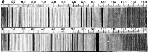
Fig. 191.—Fräunhofer’s Spectrum Lines.
The spectroscope seems likely to be of almost as great use in medicine as it has already proved to be in solar and terrestrial chemistry, if we may form an opinion from the large amount of literature which has appeared on the subject. The inception of this magical instrument arose on the instance of a discovery made by Dr. Wollaston in 1802, who, on making a slit in the shutter of his room, instead of a round hole, the spectrum of sunlight, instead of being composed of a number of coloured discs, was now a band of pure colours, each colour being free from admixture with the next to it. Moreover, he found that this colour band was not continuous, as Newton described it, but interrupted here and there by fine black lines.