Chapter IX · MAGNETISM
Reading edition
Magnetism.—The ancients applied the word “magnet,” magnes lapes, to certain hard black stones which possess the property of attracting small pieces of iron, and as discovered later, to have the still more remarkable property of pointing north and south when hung up by a string. At this time the magnet received the name of lodestone or “leading stone.” It is commonly, though incorrectly, spelled loadstone.
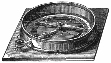
Fig.
93.—Simple compass. It consists of a magnetic needle resting on a steel pivot, protected by a brass case covered with glass, and a graduated circle marked with the letters N, E, S, W, to indicate the cardinal points;
a b
is a lever which arrests the needle by pushing it against the glass when the button
d
is pressed.
Ques. Describe two kinds of magnetism.
Ans. Magnets have two opposite kinds of magnetism or magnetic poles, which attract or repel each other in much the same way as would two opposite kinds of electrification.
Ques. What is the nature of each kind of magnetism?
Ans. One has a tendency to move toward the north and the other toward the south.
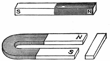
Figs.
94 to 96.—Simple
bar magnet
and
horse shoe magnet
with
keeper
. These are known as
permanent magnets
in distinction from
electromagnets
. The horse shoe magnet will attract more than the bar magnet because both poles act together. A piece of soft iron, or keeper is placed across the ends of a horse shoe magnet to assist in preventing the loss of magnetism.
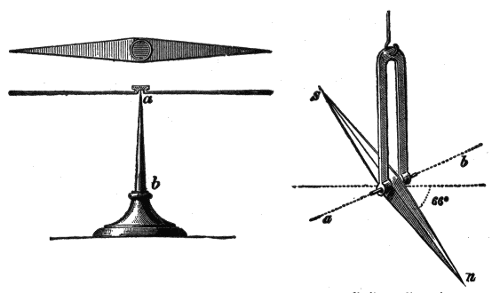
Figs.
97 and 98.—Horizontal magnetic needle, and magnetic “dip” needle. A magnetic needle consists of a small bar magnet, supported upon a pivot or suspended so that it is free to turn in a horizontal or vertical plane. The form of magnetic needle illustrated in fig. 97 is arranged to show the magnetic meridian; the needle moves upon a perpendicular axis or pivot
ab
. In fig. 98, the needle
sn
turns upon a horizontal axis
ab
. This needle indicates the dip or inclination, that is, the angle which it makes with the horizontal plane, due to the fact that in most places the lines of force are not horizontal. In the northern hemisphere the N pole of the needle is depressed, in the southern hemisphere the S pole is similarly affected. When used, the dip needle must be set so that the plane in which the needle swings contains the magnetic meridian, as indicated by the horizontal needle.
Ques. Where is the magnetism the strongest?
Ans. In two regions called the poles.
Ques. Describe the distribution of magnetism in a long shaped magnet.
Ans. The strongest magnetism resides in the ends, while all around the magnet half way between the poles there is no attraction at all.
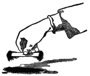
Fig.
99.—Magnetic poles. If a bar magnet be plunged into iron filings and then lifted, as illustrated in the figure, a mass of filings will cling to the ends of the magnet but not to the middle. The ends are called the
poles
of the magnet.
Ques. How are the poles designated?
Ans. They are called the north pole and the south pole.
Ques. What is the distinguishing feature of each?
Ans. The north pole points approximately to the earth’s geographical north, while the south pole of a magnet points approximately to the earth’s geographical south.
The north pole is the positive (+) pole and the south pole is the negative. The north and south poles were formerly called in France, the austral and boreal poles respectively.
Magnetic Field.—When a straight bar magnet is held under a piece of card board upon which iron filings are sprinkled, the filings will arrange themselves in curved lines radiating from the poles. If a horse shoe magnet be held at right angles to the plane of the card board, the filings will arrange themselves in curved lines, as shown in fig. 108. These lines are called magnetic lines of force or simply lines of force; they show that the medium surrounding a magnet is in a state of stress, the space so affected being called the magnetic field.

Fig.
100.—Badly magnetized bar. Properly magnetized magnets have only two poles; it is possible, however, by special or careless magnetization, to produce magnets with more than two poles, but no process will produce a magnet with a single pole. If an abnormal magnet with more than two poles be dipped into iron filings, the latter will adhere at places other than the two ends, as shown in the illustration. The polarities are alternately N and S; that is, the regions N, B, N, have north polarity, while A and C have south polarity. These are known as
consequent poles
.
Figs.
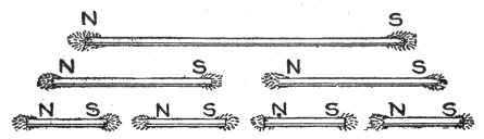
101 to 107.—Effect of breaking a magnet into several parts. If a magnetized needle be broken, each part will be found to be a complete magnet having a N and S pole. The sub-division may be continued indefinitely, but always with the same result as indicated in the figure. This is evidence of the correctness of the molecular theory of magnetism, which states that
the molecules of a magnet are themselves minute magnets arranged in rows with their opposite poles in contact
.
Ques. What is the extent and character of the magnetic field?
Ans. The influence of a magnet is supposed to extend in all directions indefinitely, however, the effect is very slight beyond a comparatively limited area.
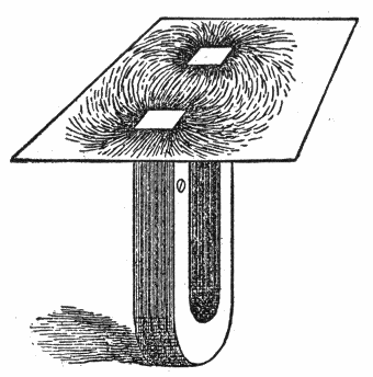
Fig.
108.—The region about a magnet in which its magnetic forces can be detected is called the
magnetic field
. This can be represented graphically by placing a piece of cardboard over the magnet and sprinkling iron filings on the paper, gently tapping at the same time. Each filing becomes a temporary magnet by
induction
, and sets itself, like the compass needle, in the direction of the
line of force
of the magnetic field.
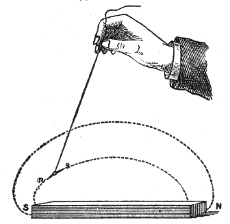
Fig.
109.—Tracing lines of force with a suspended magnet. If a small magnetic needle, suspended by a thread, be held near a magnet, it will point in some fixed direction depending on the proximity of the poles of the magnet. The direction taken by the magnet is called the direction of the force at the point, and if the suspended needle be moved forward in the direction of the pole, it will trace out a curved line which will be found to start from one of the poles, and end at the other. Any number of such lines can be traced; the space filled by these lines of force is called the
magnetic field
.
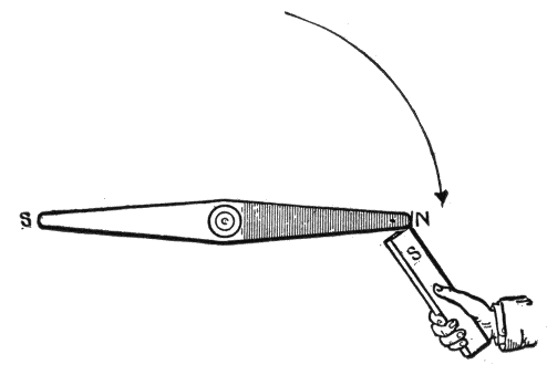
Fig.
110.—Magnetic action:
Unlike poles of magnets attract each other
.
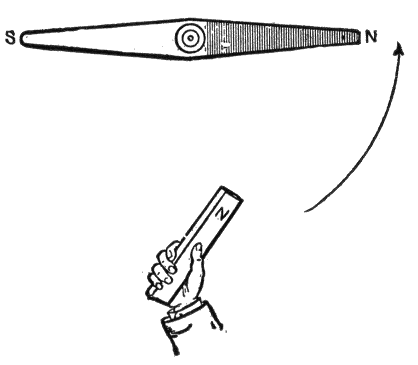
Fig.
111.—Magnetic action:
Like poles of magnets repel each other
.
Magnetic Force.—This is the force with which a magnet attracts or repels another magnet or any piece of iron or steel. The force varies with the distance, being greater when the magnet is nearer and less when the magnet is farther off. The following are the laws relating to magnetic force:
1. Like magnetic poles repel one another; unlike magnetic poles attract one another.
2. The force exerted between two magnetic poles varies inversely as the square of the distance between them.
Magnetic Circuit.—The path taken by magnetic lines of force is called a magnetic circuit; the greater part of such a circuit is usually in magnetic material, but there are often one or more air gaps included. The total number of lines of force in the circuit is known as the magnetic flux.
Ques. How is magnetic flux measured?
Ans. By a unit called the maxwell.
Named after James Clerk Maxwell the Scottish physicist.
Ques. What is the maxwell?
Ans. The amount of magnetism passing through every square centimetre of a field of unit density.
Ques. What is the unit of field strength?
Ans. The gauss.
Ques. What is a gauss?
Ans. The intensity of field which acts on a unit pole with a force of one dyne. It is equal to one line of force per square centimetre. Named after Karl Friedrich Gauss, the German mathematician.
The Magnetic Effect of the Current.—Hans Christian Oerstead, the Danish scientist, discovered in 1819 that a magnet tends to set itself at right angles to a wire carrying an electric current. He also found that the way in which the needle turns, whether to the right or left of its usual position, depends: 1, upon the position of the wire that carries the current, whether it be above or below the needle, and 2, on the direction in which the current flows through the wire.
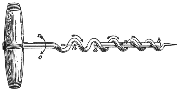
Fig.
112.—Illustrating Maxwell’s “corkscrew rule” for relative directions of current and lines of force. According to the rule:
the direction of the current and that of the resulting magnetic force are in the same relation to each other as is the forward travel and rotation of an ordinary corkscrew
, Thus, in the figure, if a current flow through the wire
ab
in the direction from
a
to
b
, the magnetic lines will encircle the wire in the direction of the curved arrow
ro
which shows the direction in which the corkscrew must be turned to advance in the direction of the arrow
n
.
To keep these movements in mind numerous rules have been suggested, of which the following will be found convenient:
Corkscrew Rule.—If the direction of travel of a right handed corkscrew represent the direction of the current in a straight conductor, the direction of rotation of the corkscrew will represent the direction of the magnetic lines of force.
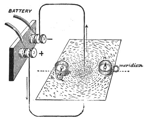
Fig.
113.—Experiment showing direction of lines of force in the magnetic field surrounding a conductor carrying an electric current. A piece of copper wire is pierced through the center of a sheet of cardboard, and carried vertically for two or three feet then bent around to the terminals of a battery or other source of current. If iron filings be sprinkled over the card while the current is passing, they will arrange themselves in circles around the wire, thus indicating the form of the magnetic field surrounding the conductor. Compass needles may also be used to show the direction of the lines of force at any point.
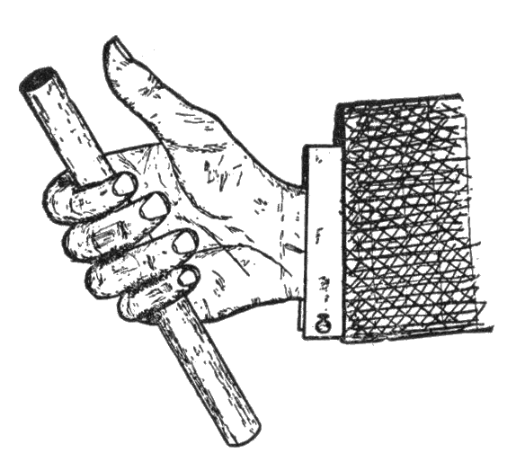
Fig.
114.—Right hand rule to determine the direction of magnetic field around a conductor carrying a current. The thumb of the right hand is placed along the conductor, pointing in the direction in which the current is flowing, then, if the fingers be partly closed, as shown in the illustration, the finger tips will point in the direction of the magnetic whirls.
Ques. What is the effect of a current flowing in a loop of wire?
Ans. If, in figs. 116 and 117, the current flow in the direction indicated by the arrow, the lines for magnetic force are found to surround the loop as shown; all the lines leave on one side of the loop and return on the other; accordingly, a north pole is formed on one side, and a south pole on the other.
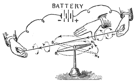
Fig.
115.—Right hand palm rule to determine the direction of the magnetic field around a conductor carrying a current: Place the palm of the outstretched right hand above and to the right side of the wire with the fingers pointing in the direction of the current, and the thumb extended at right angles, that is, pointing downward. The direction in which the thumb points will indicate the direction of the magnetic whirls.
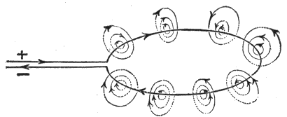
Fig.
116.—Lines of force of a circular loop. If a current flow through the loop in the direction indicated, the lines of force both inside and outside the loop, will cross the plane of the loop at right angles, and all those which cross the loop on the inside will pass through the plane in one direction (downwards in the figure), while all on the outside will return through the plane in the opposite direction.
Solenoids.—A solenoid consists of a spiral of conducting wire wound cylindrically so that, when an electric current passes through it, its turns are nearly equivalent to a succession of parallel circular circuits, and it acquires magnetic properties similar to those of a bar magnet.
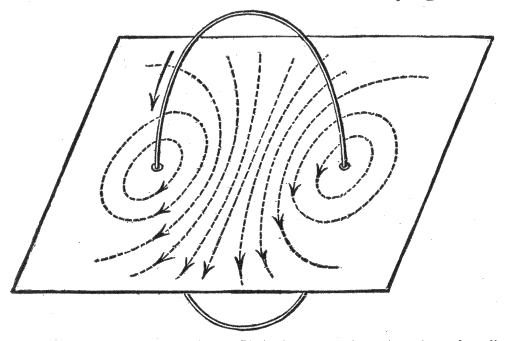
Fig.
117.—Lines of force of a circular loop. If the loop pass through a piece of cardboard at right angles to its plane, and the current flow as indicated, the dotted lines on the cardboard will represent the direction of the lines of force in the plane of the cardboard. The student should verify the lines of force as here given by applying the corkscrew rule.
Ques. What is the character of the lines of force of a solenoid in which a current is flowing?
Ans. The lines of force must be thought of as closed loops linked with the current. The conductor conveying the current passes through all the loops of force, and these are, so to speak, threaded or slung on the current-line of flow, as in fig. 116.
Ques. What is the distribution of the lines of force?
Ans. The lines of force form continuous closed curves running through the interior of the coil; they issue from one end and enter into the other end of the coil, as shown in fig. 117.
Ques. What are the properties of a solenoid?
Ans. A solenoid has north and south poles, and in fact possesses all the properties of an ordinary permanent magnet, with the important difference that the magnetism is entirely under control.
Since a solenoid carrying a current attracts and repels by its extremities the poles of a magnet, two such solenoids will attract and repel each other.
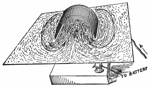
Fig.
118.—Magnetic field of a solenoid. This is best observed by cutting a piece of cardboard and fitting it around the solenoid, as shown. If iron filings be sprinkled on the cardboard and a current passed through the solenoid, the character of the field is indicated. With the current in the direction shown, it will be found that wherever small compass needles are placed, the direction in which their north poles turn is along arrows marked on the card. The card only exhibits the field in one of the sectional planes of the coil, but it is obvious that the field is the same for all sectional planes.
Ques. How does the magnetic strength of a solenoid vary?
Ans. It is proportional to the strength of the electric current passing through it.
Ques. On what, besides the current strength, does the magnetizing power of a solenoid depend?
Ans. The magnetic effect or the magnetizing power is proportional to the number of turns of wire composing the coil.
Ques. How may the magnetizing power of a solenoid be increased?
Ans. By inserting in the solenoid an iron core or round bar of soft iron.
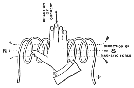
Fig.
119.—Right hand rule for polarity of a solenoid: If the solenoid be grasped in the right hand, so that the fingers point in the direction in which the current is flowing in the wires, the thumb extended will point in the direction of the north pole.
Ques. Describe the action of an iron core.
Ans. At first, the presence of an iron core greatly increases the strength of the field; after a time, however, as the strength of the current flowing in the exciting coils is increased, the conductibility of the iron for the lines of force appears to decrease, until a point is eventually reached when the presence of the iron core appears to have no effect in increasing the strength of the field.
Permeability.—Permeability is a measure of the ease with which magnetism passes through any substance. It is defined as: the ratio between the number of lines of force per unit area passing through a magnetizable substance, and the magnetizing force which produces them.
Figs.
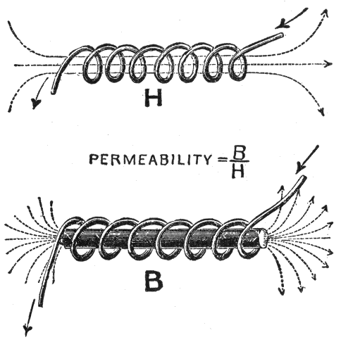
120 and 121.—Illustrating the effect of introducing an iron core into a solenoid. In the upper figure, the air space or “air core” surrounded by the solenoid offers considerable resistance to the passage of magnetic lines, allowing only a small number to pass through. If a piece of iron be introduced, as in the lower figure, the number of lines will be greatly increased. The number of lines B passing through a unit cross section of the iron core divided by the number of lines H, passing through a unit cross section of the air core is called the
permeability
and designated by the Greek letter μ.
In other words, it is the ratio of flux density to magnetizing force. Permeability is a measure of the ease with which magnetism passes through any substance. The permeability of good soft wrought iron is sometimes 3000 times that of air, varying with the quality of the iron.
Ques. What is the effect of increasing the magnetization?
Ans. The magnetic permeability decreases as the magnetization increases.
Ques. What is magnetic saturation?
Ans. The state of a magnet which has reached the highest degree of magnetization.
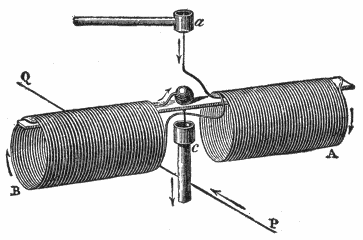
Fig.
122.—Action of currents on solenoids. To demonstrate this fact experimentally, a solenoid is constructed as shown, so that it can be suspended by two pivots in the cups
a
and
c
. The solenoid is then movable about a vertical axis, and if a rectilinear current QP be passed beneath it, which at the same time traverses the wires of the solenoid, the latter is seen to turn and set at right angles to the lower current; that is, in such a position that its circuits are parallel to the fixed current; moreover, the current in the lower part of each of the circuits is in the same direction as in the rectilinear wire. If, instead of passing a rectilinear current below the solenoid, it be passed vertically on the side, an attraction or repulsion will take place, according as the two currents in the vertical wire, and in the nearest part of the solenoid, are in the same or in contrary directions.
A magnet, just after being magnetized, will appear to have a higher degree of magnetism than it is able to retain permanently; that is, it will appear to be super-saturated, since it will support a greater weight immediately after being magnetized than it will after its armature has been once removed.
For all practical purposes, magnetic saturation may be defined as: That point of magnetization where a very large increase in the magnetizing force does not produce any perceptible increase in the magnetization.
From tests it has been shown that permeability increases with the flux density up to a certain point and then decreases, indicating that the iron is approaching a state of saturation.
Magnetomotive Force.—This is a force similar to electromotive force, that is, magnetic pressure. When a coil passes around a core several times, its magnetizing power, or magnetomotive force, (m.m.f.) is proportional both to the strength of the current and to the number of turns in the coil. The product of the current passing through the coil multiplied by the number of turns composing the coil is called the ampere turns.
It is known by experiment that one ampere turn produces 1.2566 units of magnetic pressure, hence:
magnetic pressure = 1.2566 × turns × amperes
that is,
magnetomotive force (m.m.f.) = 1.2566 × n × I.
The unit of magnetic pressure is the gilbert (named after William Gilbert, the English physicist) and is equal to
1 ÷ 1.2566 ampere turn = .7958 ampere turn.
Reluctance.—The magnetic pressure (magnetomotive force) acting in a magnetic circuit encounters a certain opposition to the production of a magnetic field, just as electromotive force in an electric circuit encounters opposition to the production of a current. In the magnetic circuit this opposition is called the reluctance; it is simply magnetic resistance and may be defined as: the resistance offered to the magnetic flux by the substance magnetized, being the ratio of the magnetomotive force to the magnetic flux.
The unit of reluctance or magnetic resistance is the oersted (named after Hans Christian Oersted, the Danish physicist) and is defined as: the reluctance offered by a cubic centimetre of vacuum.
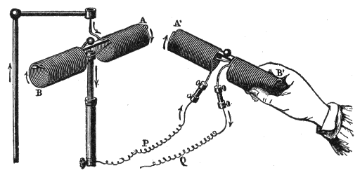
Fig.
123.—Mutual action of solenoids. When two solenoids traversed by a current are allowed to act on each other, one of them being held in the hand and the other being movable about a vertical axis, as shown in the figure, attraction and repulsion will take place just as in the case of two magnets (see figs. 110 and 111).
Analogy Between Electric and Magnetic Circuits.—The total number of magnetic lines of force, or magnetic flux, produced in any magnetic circuit will depend on the magnetic pressure (m.m.f.) acting on the circuit and the total reluctance of the circuit, just as the current in the electrical circuit depends upon the electrical pressure and the resistance of the circuit.
To make this plain, Ohm’s law states that
electric current = electromotive force / resistance or I = E/R
expressed in units
amperes = volts / ohms
The resistance, as already explained, depends on the materials of which the circuit is composed, and their geometrical shape and size.
Similarly, in the magnetic circuit, the total number of magnetic lines produced by a given magnetizing solenoid depends on the magnetic pressure, the material composing the circuit, and its shape and size.
That is,
magnetic flux = magnetomotive force / reluctance
expressed in units, the equation becomes:
maxwells = gilberts / oersteds
The gilbert is the unit of magnetomotive force, equivalent to the magnetomotive force of .7958 ampere turn.
It should be noted that in the electric circuit resistance causes heat to be generated and therefore energy to be wasted, but in the magnetic circuit reluctance does not involve any similar waste of energy.
Ques. Upon what does the reluctance of a magnetic circuit depend?
Ans. The reluctance is directly proportional to the length of the circuit, and inversely proportional to its cross sectional area.
The reluctance of a magnetic circuit is calculated according to the following equation:
reluctance = length in centimetres / (permeability × cross section in square centimetres)
Hysteresis.—The term hysteresis has been given by Ewing to the subject of lag of magnetic effects behind their causes. Hysteresis means to “lag behind,” hence its application to denote the lagging of magnetism, in a magnetic metal, behind the magnetizing flux which produces it.
Ques. What is the cause of hysteresis?
Ans. It is due to the friction between the molecules of iron or other magnetic substance which requires an expenditure of energy to change their positions.
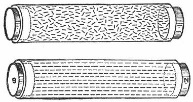
Figs
. 124 and 125.—Experiment illustrating the molecular theory of magnetism. Coarse steel filings are placed inside a small glass tube and the contents magnetized. It will be found that filings which at first had no definite arrangement will rearrange themselves under the influence of magnetic force, and assume symmetrical positions, each one lying in line with, or parallel to its neighbor, as shown in the lower figure.
Ques. When do the molecules change their positions?
Ans. Both in the process of magnetization and demagnetization.
Ques. What becomes of the loss of energy due to hysteresis?
Ans. It is converted into heat in changing the positions of the molecules during magnetization and demagnetization.
Ewing gives the value for the energy in ergs dissipated per cubic centimetre, for a complete cycle of doubly reversed strong magnetization for a number of substances as follows:
SubstanceEnergy dissipated (ergs)
Very soft annealed iron9,300
Less soft annealed iron16,300
Hard drawn steel wire60,000
Annealed steel wire70,000
Same steel glass hard76,000
Piano steel wire annealed94,000
Piano steel wire normal temper116,000
Piano steel wire glass hard117,000
Approximately 28 foot pounds of energy are converted into heat in making a double reversal of strong magnetization in a cubic foot of iron.
Residual Magnetism.—When a mass of iron has once been magnetized, it becomes a difficult matter to entirely remove all traces when the magnetizing agent has been removed, and, as a general rule, a small amount of magnetism is permanently retained by the iron. This is known as residual magnetism, and it varies in amount with the quality of the iron.
Well annealed, pure wrought iron, as a rule, possesses very little residual magnetism, while, on the other hand, wrought iron, which contains a large percentage of impurities, or which has been subjected to some hardening process, such as hammering, rolling, stamping, etc., and cast iron, possess a very large amount of residual magnetism.
Residual magnetism in iron is of great importance in the working of the self-exciting dynamo, and is, indeed, the essential principle of this class of machine.
That is, without residual magnetism in the field magnet core, the dynamo when started would not generate any current unless it received an initial excitation from an external source.