Chapter III · THE ELECTRIC CURRENT
Reading edition
The ordinary statement that an electric current is flowing along a wire is only a conventional way of expressing the fact that the wire and the space around the wire are in a different state from that in which they are when no electric current is said to be flowing.
In order to make laymen understand the action of this so called current, it is generally compared with the flow of water.
In comparing hydraulics and electricity, it must be borne in mind, however, that there is really no such thing as an “electric fluid,” and that water in pipes has mass and weight, while electricity has none. It should be noted, however, that electricity is conveniently spoken of as having weight in explaining some of the ways in which it manifests itself.
All electrical machines and batteries are merely instruments for moving electricity from one place to another, or for causing electricity, when accumulated in one place, to do work in returning to its former level of distribution.
The head or pressure in a standpipe is what causes water to move through the pipes which offer resistance to the flow.
Similarly, the conductors, along which the electric current is said to flow, offer more or less resistance to the flow, depending on the material. Copper wire is generally used as it offers little resistance.
The current must have pressure to overcome the resistance of the conductor and flow along its surface. This pressure is called voltage caused by what is known as difference of potential between the source and terminal.
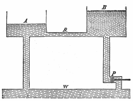
Fig.
35.—Analogy of the flow of water to the electric current. The water in the reservoirs A and B stands at different heights. As long as this difference of level is maintained, water from B will flow through the pipe R to A. If by means of a pump P the level in B be kept constant, flow through R will also be maintained. Here, by means of the work expended on the pump, the level in the reservoir is kept constant; and in the corresponding case of the electric current, by the conversion of chemical energy a constant difference of potential is maintained.
The pressure under which a current flows is measured in volts and the quantity that passes in amperes. The resistance with which the current meets in flowing along a conductor is measured in ohms.
Ques. What is a volt?
Ans. A volt is that electromotive force (E. M. F.) which produces a current of one ampere against a resistance of one ohm.
Ques. What is an ampere?
Ans. An ampere is the current produced by an E. M. F. of one volt in a circuit having a resistance of one ohm. It is that quantity of electricity which will deposit .005084 grain of copper per second.
Ques. What is an ohm?
Ans. An ohm is equal to the resistance offered to an unvarying electric current by a column of mercury at 32° Fahr., 14.4521 grams in mass, of a constant cross sectional area, and of the length of 106.3 centimeters.
Ohm’s Law.—In a given circuit, the amount of current in amperes is equal to the E. M. F. in volts divided by the resistance in ohms; that is:
current = pressure / resistance = volts / ohms
expressed as a formula:
I = E/R (1)
in which
I = current strength in amperes; E = electromotive force in volts; R = resistance in ohms.
From (1) is derived the following:
E = IR (2)
R = E/I (3)
From (1) it is seen that the flow of the current is proportional to the voltage and inversely proportional to the resistance; the latter depends upon the material, length and diameter of the conductor.
Since the current will always flow along the path of least resistance; it must be so guarded that there will be no leakage. Hence, to prevent leakage, wires are insulated, that is, covered by wrapping them with cotton or silk thread or other insulating material. If the insulation be not effective, the current may leak, and so return to the source without doing its work. This is known as a short circuit.
The conductor which receives the current from the source is called the lead, and the one by which it flows back, the return.
When wires are used for both lead and return, it is called a metallic circuit: when the ground is used for the return, it is called a ground circuit. An electric current is said to be:
1. Direct, when it is of unvarying direction;
2. Alternating, when it flows rapidly to and fro in opposite directions;
3. Primary, when it comes directly from the source;
4. Secondary, when the voltage and amperage of a primary current have been changed by an induction coil;
5. Low tension, when its voltage is low;
6. High tension, when its voltage is high.
A high tension current is capable of forcing its way against considerable resistance, whereas, a low tension current must have its path made easy.
Production of the Electric Current.—To produce a steady flow of water in a pipe two conditions are necessary. There must first be available a hydraulic pressure, or, as it is technically called, a “head” of water produced by a pump, or a difference of level or otherwise.
In addition to the pressure there must also be a suitable path or channel provided for the water to flow through, or there will be no flow, however great the “head,” until something breaks down under the strain. In the case just cited, although there is full pressure in the water in the pipe, there is no current of water as long as the tap remains closed. The opening of the tap completes the necessary path (the greater part of which was already in existence) and the water flows.
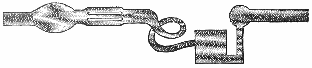
Fig.
36.—Hydraulic analogy of the electric current. If, say 10 gallons of water flow in every second into a system of vessels and pipes of any shape, whether simple or more complicated as shown in the figure, and 10 gallons flow out again per second, it is evident that through every cross section of any vessel or pipe of the system 10 gallons of water pass every second. This follows from the fact that water is an uncompressible liquid and must be practically of the same density throughout the system. The water moves slowly where the section is large and quickly where it is small, and thus the quantity of water that flows through any part of the system is independent of the cross section of that part. The same condition holds good for the electric current; if in a closed circuit a constant current circulates, the same amount of electricity will pass every cross section per second. Hence the following law:
The magnitude of a constant current in any circuit is equal in all parts of the circuit.
For the production of a steady electric current two very similar conditions are necessary. There must be a steadily maintained electric pressure, known under different aspects as “electromotive force,” “potential difference,” or “voltage.” This alone, however, is not sufficient. In addition, a suitable conducting path is necessary. Any break in this path occupied by unsuitable material acts like the closed tap in the analogous case above mentioned, and it is only when all such breaks have been properly bridged by suitable material, that is, by conductors, that the effects which denote the flow of the current will begin to be manifested.
The necessary electromotive force or voltage required to cause the current to flow may be obtained:
1. Chemically;
2. Mechanically;
3. Thermally.
In the first method, two dissimilar metals such as copper and zinc called elements, are immersed in an exciting fluid or electrolyte.
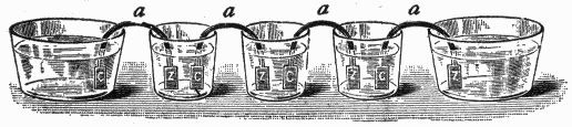
Fig.
37.—Volta’s “Crown of Cups.” The metallic elements C and Z each consisted of two metals, the plate C being of copper and the plate Z of zinc. They were placed, as shown, in the glass vessels, which contained salt water and ordinary water or lye. Into each vessel, except the two end ones, the copper end of one arc and the zinc end of the next were introduced, the series, however long, ending with copper dipping into the terminal vessel at one end and zinc into that at the other. The arrangement is almost exactly that of a modern one-fluid primary battery.
When the elements are connected at their terminals by a wire or conductor a chemical action takes place, producing a current which flows from the copper to the zinc. This device is called a cell, and the combination of two or more of them connected so as to form a unit is known as a battery. The word battery is frequently used incorrectly for a single cell. That terminal of the element from which the current flows is called the plus or positive pole, and the terminal of the other element the negative pole.
Cells are said to be primary or secondary according as they generate a current of themselves, or first require to be charged from an external source, storing up a current supply which is afterwards yielded in the reverse direction to that of the charging current.
An electric current is generated mechanically by a dynamo. In either case no electricity is produced, but part of the supply already existing is simply set in motion by creating an electric pressure.
An electric current, according to the third method, is generated directly from heat energy, as will be later explained; the current thus obtained is very feeble.
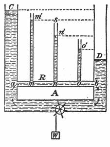
Fig.
38.—Hydrostatic analogy of fall of potential in an electrical circuit.
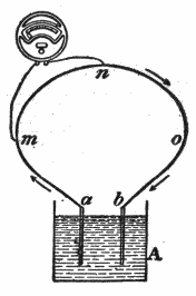
Fig.
39.—Showing method of connecting voltmeter to find potential difference between any two points as
m
and
n
on an electrical circuit.
Strength of Current.—It is important that the reader have a clear conception of this term, which is so often used. The exact definition of the strength of a current is as follows:
The strength of a current is the quantity of electricity which flows past any point of the circuit in one second.
Example.—If, during 10 seconds, 25 coulombs of electricity flow through a circuit, then the average strength of the current during that time is 21⁄2 coulombs per second, or 21⁄2 amperes.
Voltage Drop in an Electric Circuit.—A difference of potential exists between any two points on a conductor through which a current is flowing on account of the resistance offered to the current by the conductor.
For instance, in the electrical circuit shown in fig. 39, the potential at the point a is higher than that at m, that at m higher than that at n, etc., just as in the water circuit, shown in fig. 38, the hydrostatic pressure at a is greater than that at m′, that at m′ greater than that at n′, etc. The fall in the water pressure between m′ and n′ (fig. 38) is measured by the water head n’s.
In order to measure the fall in electrical potential between m and n, (fig. 39), the terminals of a volt meter are placed in contact with these points as shown. Its reading will give the difference of potential between m and n, in volts, provided that its own current carrying capacity is so small that it does not appreciably lower the potential difference between the points m and n by being touched across them; that is, provided the current which flows through it is negligible in comparison with that which flows through the conductor which already joins the points m and n.