Chapter II · STATIC ELECTRICITY
Reading edition
Static electricity may be defined simply as electricity at rest; the term properly applies to an isolated charge of electricity produced by friction. The presence of static electricity manifests itself by attraction or repulsion.
Electrical Attraction and Repulsion.—When a glass rod, or a stick of sealing wax or shellac is held in the hand and rubbed with a piece of flannel or cat skin, the parts will be found to have the property of attracting bodies, such as pieces of silk, wool, feathers, gold leaf, etc.; they are then said to be electrified. In order to ascertain whether bodies are electrified or not, instruments called electroscopes are used.
There are two opposite kinds of electrification:
1. Positive;
2. Negative.
Franklin called the electricity excited upon glass by rubbing it with silk positive electricity, and that produced on resinous bodies by friction with wool or fur, negative electricity.
The electricity developed on a body by friction depends on the rubber as well as the body rubbed. Thus glass becomes negatively electrified when rubbed with catskin, but positively electrified when rubbed with silk.
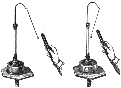
Figs.
2 and 3.—Pith ball pendulum or electroscope; the figures illustrate also electrical attraction and repulsion.
The nature of the electricity set free by friction depends on the degree of polish, the direction of the friction, and the temperature. If two glass discs of different degrees of polish be rubbed against each other, that which is most polished is positively, and that which is least polished is negatively electrified. If two silk ribbons of the same kind be rubbed across each other, that which is transversely rubbed is negatively and the other positively electrified. If two bodies of the same substance, of the same polish, but of different temperatures, be rubbed together, that which is most heated is negatively electrified. Generally speaking, the particles which are most readily displaced are negatively electrified.
In the following list, which is mainly due to Faraday, the substances are arranged in such order that each becomes positively electrified when rubbed with any of the bodies following, but negatively when rubbed with any of those which precede it:
1. Catskin.
2. Flannel.
3. Ivory.
4. Rock crystal.
5. Glass.
6. Cotton.
7. Silk.
8. The hand.
9. Wood.
10. Metals.
11. Caoutchouc.
12. Sealing wax.
13. Resin.
14. Sulphur.
15. Gutta-percha.
16. Gun cotton.
The Charge.—The quantity of electrification of either kind produced by friction or other means upon the surface of a body is spoken of as a charge, and a body when electrified is said to be charged. It is clear that there may be charges of different values as well as of either kind. When the charge of electricity is removed from a charged body it is said to be discharged. Good conductors of electricity are instantaneously discharged if touched by the hand or by any conductor in contact with the ground, the charge thus finding a means of escaping to earth. A body that is not a good conductor may be readily discharged by passing it rapidly through the flame of a lamp or candle; for the flame instantly carries off the electricity and dissipates it in the air.
Distribution of the Charge.—When an insulated sphere of conducting material is charged with electricity, the latter passes to the surface of the sphere, and forms there an extremely thin layer. The distribution of the charge then, depends on the extent of the surface and not on the mass.
Boit proved that the charge resides on the surface by the following experiment:
A copper ball was electrified and insulated. Two hollow hemispheres of copper of a larger size, provided with glass handles, were then placed near the sphere, as in fig. 4. So long as they did not touch the sphere, the charge remained on the latter, but if the hemispheres touched the inner sphere, the whole of the electricity passed to the exterior, and when the hemispheres were separated and removed the inner globe was found to be completely discharged.
The distribution of a charge over an insulated sphere of conducting material is uniform, provided the sphere is remote from all other conductors and electrified bodies.
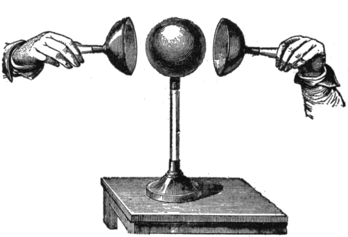
Fig.
4.—Boit’s experiment which proved that the
charge resides on the surface
.
Figs. 5 to 8 show, by the dotted lines, the distribution of a charge for bodies of various shapes. Fig. 6 shows that for elongated bodies, the charge collects at the ends.
The effects of points is illustrated in fig. 9; when a charged body is provided with a point as here shown, the current accumulates at the point to such a high degree of density that it passes off into the air, and if a lighted candle be held in front of the point, the flame will be visibly blown aside.
Fig. 10 shows an electric windmill or experimental device for illustrating the escape of electricity from points. It consists of a vane of several pointed wires bent at the tips in the same direction, radiating from a center which rests upon a pivot. When mounted upon the conductor of an electrostatic machine, the vane rotates in a direction opposite that of the points. The movement of the vane is due to the repulsion of the electrified air particles near the points and the electricity on the points themselves. The motion of the air is called electric wind. This device is also called electric flyer, and electric whirl.
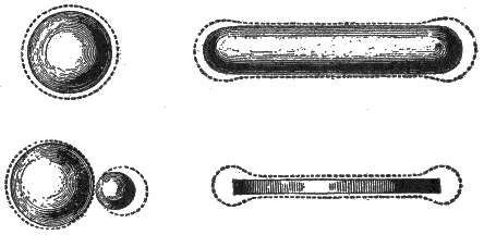
Figs.
5 to 8.—Illustrating the distribution of the charge on conductors of various shapes.
“Free” and “Bound” Electricity.—These terms may be defined as follows:
The expression free electricity relates to the ordinary state of electricity upon a charged conductor, not in the presence of a charge of the opposite kind. A free charge will flow away to the earth if a conducting path be provided.
A charge of electricity upon a conductor is said to be bound, when it is attracted by the presence of a neighboring charge of the opposite kind.
Conductors and Insulators.—The term conductors is applied to those bodies which readily allow electricity to flow through them, in distinction from insulators or so-called non-conductors, which practically allow no flow of electricity.
Strictly speaking, there is no substance which will prevent the passage of electricity, hence, the term non-conductors, though extensively used, is not correct.
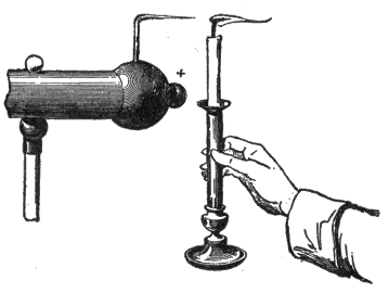
Fig.
9.—Experiment to illustrate the effect of pointed conductors.
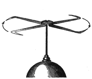
Fig.
10.—Electric windmill which operates by the reaction due to the escape of the electric charge from the points.
Electroscopes.—These are instruments for detecting whether a body be electrified or not, and indicating also whether the electrification be positive or negative. The earliest electroscope devised consisted of a stiff straw balanced lightly upon a sharp point; a thin strip of brass or wood, or even a goose quill, balanced upon a sewing needle will serve equally well. Another form of electroscope is the pith ball pendulum, shown in figs. 2 and 3. When an electrified body is held near the electroscope it is attracted or repelled thus indicating the presence and nature of the charge.
Gold Leaf Electroscope.—This form of electroscope, which is very sensitive, was invented by Bennet. Its operation depends on the fact that like charges repel each other.
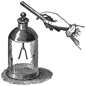
Fig.
11.—Gold leaf electroscope; it consists of two strips of gold foil suspended from a brass rod within a glass jar. Used to detect the presence and sign of an electric charge.
The gold leaf electroscope as shown in fig. 11, is conveniently made by suspending the two narrow strips of gold leaf within a wide mouthed glass jar, which both serves to protect them from draughts of air and to support them from contact with the ground. A piece of varnished glass tube is pushed through the cork, which should be varnished with shellac or with paraffin wax. Through this passes a stiff brass wire, the lower end of which is bent at a right angle to receive the two strips of gold leaf, while the upper end is attached to a flat plate of metal, or may be furnished with a brass knob.
When kept dry and free from dust it will indicate excessively small quantities of electricity. A rubbed glass rod, even while two or three feet from the instrument, will cause the leaves to repel one another. If the knob be brushed with only a small camel’s hair brush, the slight friction produces a perceptible effect. With this instrument all kinds of friction can be shown to produce electrification.
The gold leaf electroscope can be further used to indicate the kind of electricity on an excited body. Thus, if a piece of brown paper be rubbed with a piece of india rubber, the nature of the charge is determined as follows:
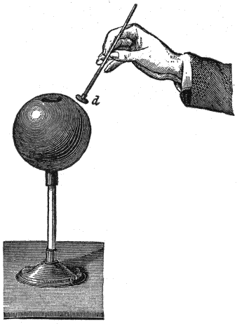
Fig.
12.—Distribution of electrification on a charged hollow sphere. If an insulated conductor
d
be inserted through the opening in the sphere and brought in contact with the interior surface and afterwards carefully removed, it will be found, by testing with the gold leaf electroscope, that it has received no charge. If touched to the outside, however, the conductor will receive part of the charge.
First charge the gold leaves of the electroscope by touching the knob with a glass rod rubbed on silk. The leaves diverge, being electrified with positive electrification. When they are thus charged the approach of a body which is positively electrified will cause them to diverge still more widely; while, on the approach of one negatively electrified, they will tend to close together. If now the brown paper be brought near the electroscope, the leaves will be seen to diverge more, proving the electrification of the paper to be of the same kind as that with which the electroscope is charged.
The gold leaf electroscope will also indicate roughly the amount of electricity on a body placed in contact with it, for the gold leaves open out more widely when the quantity of electricity thus imparted to them is greater.
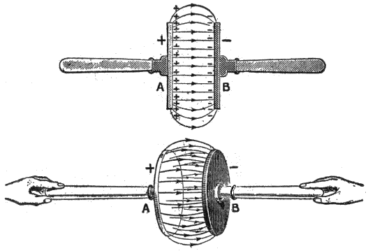
Figs.
13 and 14.—Electrification produced by rubbing dissimilar bodies together and then separating them. If the insulated glass and leather discs A and B be rubbed together,
but not separated
, no signs of electrification can be detected; but if the discs be drawn apart a little distance the space between them is found to be an electric field, and as they separate farther and farther, electric forces will be found to exist in more and more of the surrounding space, the electrification being indicated by “lines of force.” It should be noted that
work has to be done
in separating the charged discs to overcome the attraction which tends to hold them together. The stress indicated by the lines of force consists of a tension or pull in the direction of their length and a pressure or thrust at right angles to that direction.
Electric Screens.—That the charge on the outside of a conductor always distributes itself in such a way that there is no electric force within the conductor was first proved experimentally by Faraday. He covered a large box with tin foil and went inside with the most delicate electroscopes obtainable. Faraday found that the outside of the box could be charged so strongly that long sparks would fly from it without any electrical effects being observable anywhere inside the box.
To repeat the experiment in modified form, let an electroscope be placed beneath a bird cage or wire netting, as in fig. 15. Let charged rods or other powerfully charged bodies be brought near the electroscope outside the cage. The leaves will be found to remain undisturbed.
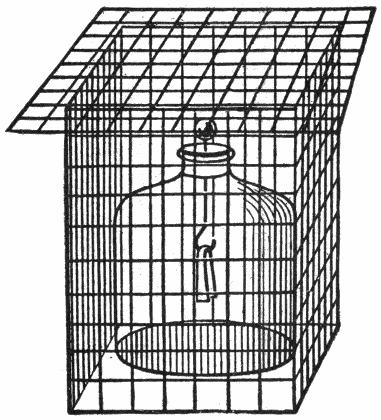
Fig.
15.—The electric screen. A screen of wire gauze surrounding a delicate electrical instrument will protect it from external electrostatic induction.
Electrification by Induction.—An insulated conductor, charged with either kind of electricity, acts on bodies in a neutral state placed near it in a manner analogous to that of the action of a magnet on soft iron; that is, it decomposes the neutral electricity, attracting the opposite and repelling the like kind of electricity. The action thus exerted is said to take place by influence or induction.
The phenomenon of electrification by induction may be demonstrated by the following experiment:
In fig. 16, let the ebonite rod be electrified by friction and slowly brought toward the knob of the gold leaf electroscope. The leaves will be seen to diverge, even though the rod does not approach to within a foot of the electroscope.
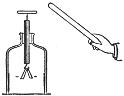
Fig.
16.—Experiment to illustrate electrostatic induction. The leaves will diverge, even though the charged ebonite rod does not approach to within a foot of the electroscope.
This experiment shows that the mere influence which an electric charge exerts upon a conductor placed in its vicinity is able to produce electrification in that conductor. This method of producing electrification is called electrostatic induction.
As soon as the charged rod is removed the leaves will collapse, indicating that this form of electrification is only a temporary phenomenon which is due simply to the presence of the charged body in the neighborhood.
Nature of the Induced Charge.—This is shown by the experiment illustrated in fig. 17.
Let a metal ball A be charged by rubbing it with a charged rod, and let it then be brought near an insulated metal cylinder B which is provided with pith balls on strips of paper C, D, E, as shown.
The divergence of C and E will show that the ends of B have received electrical charges because of the presence of A, while the failure of D to diverge will show that the middle of B is uncharged. Further, the rod which charged A will be found to repel C but to attract E.
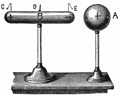
Fig.
17.—Experiment illustrating the nature of an induced charge. The apparatus consists of a metal ball and cylinder, both mounted on insulated stands, pith balls being placed on the cylinder at points C, D, and E.
From these experiments, the conclusion is that when a conductor is brought near a charged body, the end away from the inducing charge is electrified with the same kind of electricity as that on the inducing body, while the end toward the inducing body receives electricity of opposite sign.
The Electrophorus.—This is a simple and ingenious instrument, invented by Volta in 1775 for the purpose of procuring, by the principle of induction, an unlimited number of charges of electricity from one single charge.
It consists of two parts, as shown in fig. 19, a round cake of resinous material B, cast in a metal dish or “sole” about one foot in diameter, and a round disc A, of slightly smaller diameter made of metal or of wood covered with tinfoil, and provided with a glass handle. Shellac, or sealing wax, or a mixture of resin shellac and Venice turpentine, may be used to make the cake.
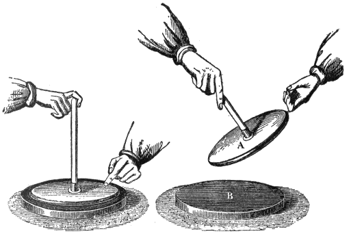
Figs.
18 and 19.—The electrophorus and method of using. Charge B; place A in contact with B, and touch A (fig. 18). The disc is now charged by
induction
and will yield a spark when touched by the hand, as in fig. 19.
To use the electrophorus, the resinous cake B must be first beaten or rubbed with fur or a woolen cloth, the disc A is then placed on the cake, touched with the finger and then lifted by the handle. The disc will now be found to be charged and will yield a spark when touched with the hand, as in fig. 19.
The “cover” may be replaced, touched, and once more removed, and will thus yield any number of sparks, the original charge on the resinous plate meanwhile remaining practically as strong as before.
The theory of the electrophorus is very simple, provided the student has clearly grasped the principle of induction.
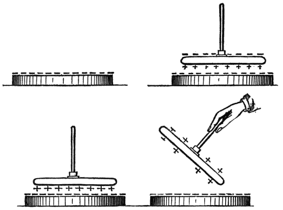
Figs.
20 to 23.—Illustrating “how the electrophorus works.”
When the resinous cake is first beaten with the cat’s skin its surface is negatively electrified, as indicated in fig. 20. Again, when the metal disc is placed down upon it, it rests really only on three or four points of the surface, and may be regarded as an insulated conductor in the presence of an electrified body. The negative electrification of the cake therefore acts inductively on the metallic disc or “cover,” attracting a positive charge to its under side, and repelling a negative charge to its upper surface, as shown in fig. 21.
If, now, the cover be touched for an instant with the finger, the negative charge of the upper surface (which is upon the upper surface being repelled by the negative charge on the cake) will be neutralized by electricity flowing in from the earth through the hand and body of the experimenter. The attracted positive charge will, however remain being bound as it were by its attraction towards the negative charge on the cake.
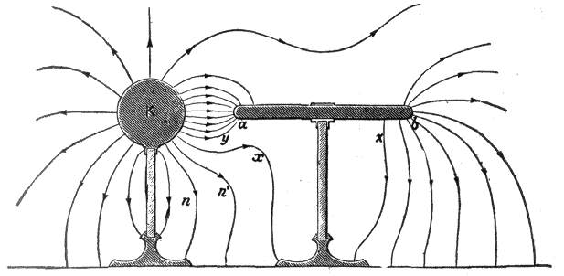
Fig.
24.—Lines of force of a charged sphere and a conductor under induction. The negative electrification on the end
a
of the cylinder indicates that a certain number of lines end there, while the positive electrification on the end
b
similarly indicates that an
equal
number of lines set out from that end. It is one of the fundamental properties of a conductor that it yields instantly to the smallest electric force, and that no electric force can be permanently maintained within the substance of a conductor in which no current is passing. There can, therefore, be no electrostatic strain and no lines of force within the material of a conductor where the electric field has become steady. Hence the lines starting from
b
are entirely distinct from those ending at
a
. The two sets are equal in number because no charge has been given to the cylinder, either positive or negative, and therefore the sum of all the positive electrifications (or lines starting from
b
) must be equal to the sum of all the negative electrifications (or the lines ending at
a
). In all nine lines have been drawn at each end of the cylinder, leaving the thirteen lines emanating from the sphere which do not run on to the cylinder. If the cylinder be withdrawn to a distance from K, it (the cylinder) will be found to show no signs of electrification.
Fig. 22 shows the result after the cover has been touched. If, finally, the cover be lifted by its handle, the remaining positive charge will no longer be “bound” on the lower surface by attraction, but will distribute itself on both sides of the cover, and may be used to give a spark. It is clear that no part of the original charge has been consumed in the process, which may be repeated as often as desired. As a matter of fact, the charge on the cake slowly dissipates—especially if the air be damp. Hence it is needful sometimes to renew the original charge by again beating the cake with the cat’s skin.
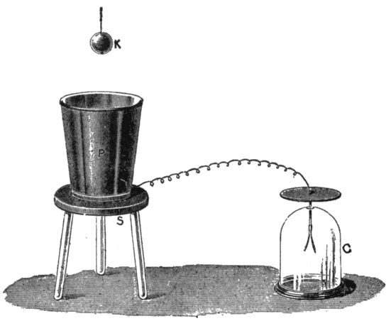
Fig.
25.—Faraday’s ice-pail experiment. An ice-pail P connected with the gold leaves of an electroscope C, is placed on an insulating stand S. A charged conductor K, carried by a silk thread, is lowered into the pail, and finally touches it at the bottom. While it is being lowered the leaves of the electroscope diverge farther and farther, until K is well within the pail, after which they diverge no more, even when K touches the pail or is afterwards withdrawn by the insulating thread. After withdrawal, K is found to be completely discharged.
The labor of touching the cover with the finger at each operation may be saved by having a pin of brass or a strip of tinfoil projecting from the metallic “sole” on to the top of the cake, so that it touches the plate each time, and thus neutralizes the negative charge by allowing electricity to flow in from the earth.
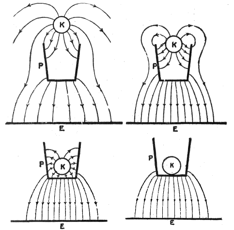
Figs.
26 to 29.—Explanation of Faraday’s ice pail experiment. For simplicity the electroscope, insulating stand and silk thread have been omitted. Only the three principal conductors K, P, and the earth E are shown. In fig. 26 the ball K is sufficiently close to P to act inductively on it; six lines are shown as falling on P, and the other six as passing to E by different paths. Corresponding to the six lines falling on P from K, six others pass to E from the lower surfaces. In fig. 27 where K is just entering the pail, two lines only pass from K to E through the dielectric; the remaining ten fall on P, and ten others starting from the distant parts of P pass to E. In fig. 28, K is so far within P that none of its lines can reach E through the dielectric; they all fall on P and from the outside of P an equal number start and pass through the dielectric to E. It is evident that in this position K can be moved about within P, without affecting the outside distribution in the slightest, and that even when K touches P as shown in fig. 29, and when, therefore, all lines between them disappear, the lines in the dielectric outside remain just as they are in fig. 28. K is now completely discharged, since lines no longer emanate from it, hence it can be removed by the silk cord without disturbing the electrification of P. If K be again charged and introduced into P it will be again discharged, for the fact that P is already charged will have no effect on the final result, provided when K touches P it is well
under cover
.
Since the electricity thus yielded by the electrophorus is not obtained at the expense of any part of the original charge, it is a matter of some interest to inquire whence is the source from which the energy of this apparently unlimited supply is drawn; for it cannot be called into existence without the expenditure of some other form of energy. The fact is, more work is done in lifting the cover when it is charged with the positive electricity than when it is not charged; for when charged, there is the force of the electric attraction to be overcome as well as the force of gravity; this excess force is the real origin of the energy stored up in the separate charges.
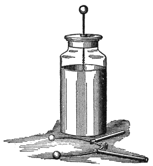
Figs.
30 and 31.—The Leyden jar and discharger. Its discovery is attributed to the attempt of Musschenbrock and his pupil Cuneus to collect the supposed electric “fluid” in a bottle half filled with water. The bottle was held in the hand and was provided with a nail to lead the “fluid” down through the cork to the water from the electric machine. The invention of the Leyden jar is also claimed by Kleist, Bishop of Pomerania.
Condensers; Leyden Jar.—A condenser is an apparatus for condensing a large quantity of electricity on a comparatively small surface. The form may vary considerably, but in all cases it consists essentially of two insulated conductors, separated by an insulator and the working depends on the action of induction.
A form of condenser generally used in making experiments on static electricity is the Leyden jar, so named from the town of Leyden where it was invented. It consists of a glass jar coated inside and out to a certain height with tinfoil, having a brass rod terminating in a knob passed through a wooden stopper, and connected to the inner coat by a loose chain, as shown in fig. 30.
The jar may be charged by repeatedly touching the knob with the charged plate of the electrophorus or by connecting the inner coating to one knob of an electrical machine and the outer coating to the other knob.
The discharge of a condenser is effected by connecting the plates having an opposite charge. This may be done by use of a wire or a discharger, as shown in fig. 31; the connection is made between the outer coat and the knob.
When the knob of the discharger is sufficiently close to the knob of the jar, a bright spark will be observed between the knobs. This discharge occurs whenever the difference of potential between the coats is great enough to overcome the resistance of the air between the knobs.
Let a charged jar be placed on a glass plate so as to insulate the outer coat. Let the knob be touched with the finger. No appreciable discharge will be noticed. Let the outer coat be in turn touched with the finger. Again no appreciable discharge will appear. But if the inner and outer coatings be connected with the discharger, a powerful spark will pass.
Electric Machines.—Various machines have been devised for producing electric charges such as have been described. The ordinary “static” or electric machine, is nothing but a continuously acting electrophorus.
Fig. 32 represents the so-called Toepler-Holtz machine. Upon the back of the stationary plate E, are pasted paper sectors, beneath which are strips of tinfoil AB and CD called inductors.
In front of E is a revolving glass plate carrying discs l, m, n, o, p and q, called carriers.
To the inductors AB and CD are fastened metal arms t and u, which bring B and C into electrical contact with the discs l, m, n, o, p and q, when these discs pass beneath the tinsel brushes carried by t and u.
A stationary metallic rod rs carries at its ends stationary brushes as well as sharp pointed metallic combs.
The two knobs R and S have their capacity increased by the Leyden jars L and L′.
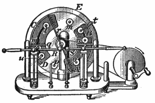
Fig.
32.—The Toepler-Holtz electric machine.
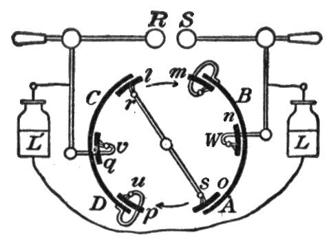
Fig.
33.—Principle of Toepler-Holtz electric machine.
Action of the Toepler-Holtz Machine.—The action of the machine described above is best understood from the diagram of fig. 33. Suppose that a small + charge is originally placed on the inductor CD. Induction takes place in the metallic system consisting of the discs l and o and the rod rs, l becoming negatively charged and o positively charged. As the plate carrying l, m, n, o, p, q rotates in the direction of the arrow the negative charge on l is carried over to the position m, where a part of it passes over to the inductor AB, thus charging it negatively.
When l reaches the position n the remainder of its charge, being repelled by the negative electricity which is now on AB, passes over into the Leyden jar L.
When l reaches the position o it again becomes charged by induction, this time positively, and more strongly than at first, since now the negative charge on AB, as well as the positive charge on CD, is acting inductively upon the rod rs.
When l reaches the position u, a part of its now strong positive charge passes to CD, thus increasing the positive charge upon this inductor.
In the position v the remainder of the positive charge on l passes over to L′. This completes the cycle for l. Thus as the rotation continues AB and CD acquire stronger and stronger charges, the inductive action upon rs becomes more and more intense, and positive and negative charges are continuously imparted to L′ and L until a discharge takes place between the knobs R and S.
There is usually sufficient charge on one of the inductors to start the machine, but in damp weather it will often be found necessary to apply a charge to one of the inductors by means of the ebonite or glass rod before the machine will work.
The Wimshurst Machine.—The essential parts of an ordinary Wimshurst machine, as shown in fig. 34, are two insulating plates or drums. On each plate are fixed a large number of strips of conducting material, which are equal in size and are equally spaced—radially if on a plate, and circumferentially if on a drum. The plates, or drums, are made to rotate in opposite directions. The capacity of the inductors therefore varies from a maximum when each strip on one plate is facing a strip on the other, to a minimum when the conducting strips on each plate are facing blank or insulating portions of the other plate.
There are three pairs of contact brushes, the members of two of the pairs being at opposite ends of diametrical conducting rods placed at right angles to one another; the third pair are insulated from one another and form the principal collectors, the one giving positive and the other negative electricity.
The plates are revolving in opposite directions; thus if there be a charge on one of the conducting segments of one plate and an opposite charge on one of the conducting segments on the other plate near it, their potential will be raised as the rotation of the plates separates them.[2]
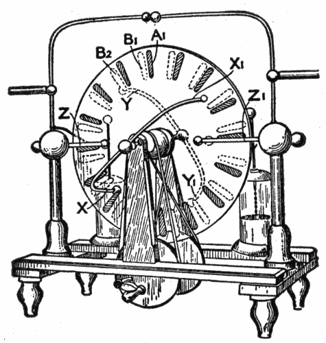
Fig.
34.—The Wimshurst Electric Machine.