Chapter VIII · EFFECTS OF THE CURRENT
Reading edition
The term “electric current,” in the present state of our knowledge, should be regarded as denoting the existence of a state of things in which certain definite experimental effects are produced, for some of which there certainly is no analogy exhibited in ordinary hydraulic currents. The following are the most important of these effects:
1. Thermal effect;
2. Magnetic effect;
3. Chemical effect.
It is rather to these effects than to any imaginary current flow in the conductor that the mind of the reader should be directed.
With this preliminary caution, which should never be lost sight of, the use of familiar words and expressions connected with the flow of water in pipes is justified in order to avoid roundabout and cumbrous phrases which, though perhaps more nearly in accord with present knowledge of the facts, would not tend to clearness or conciseness.
The three most important effects of the current just mentioned, may be presented in more detail as follows:
1. The Thermal effect:—
The conductor along which the current flows becomes heated. The rise of temperature may be small or great according to circumstances, but some heat is always produced.
2. The Magnetic effect;
The space both outside and inside the substance of the conductor, but more especially the former, becomes a “magnetic field” in which delicately pivoted or suspended magnetic needles will take up definite positions and magnetic materials will become magnetized.
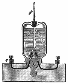
Fig.
87.—Lenz’s apparatus for measuring the heat given off by an electric current. It consisted of a wide mouthed stoppered bottle fixed upside down, with its stopper,
b
in a wooden box; the stopper was perforated so as to give passage to two thick platinum wires, connected at one end with binding screws,
s
, while their free ends were provided with platinum cones by which the wires under investigation could be readily affixed; the vessel contained alcohol, the temperature of which was indicated by a thermometer fitted in a cork inserted in a hole made in the bottom of the vessel. The current is passed through the platinum wires, and its strength measured by means of a galvanometer interposed in the circuit. By observing the increase of temperature in the thermometer in a given time and knowing the weight of the alcohol, the mass of the wire, the specific heat, and the calorimetric values of the vessel, and of the thermometer, compared with alcohol, the heating effect which is produced by the current in a given time can be calculated.
3. The Chemical effect;—
If the conductor be a liquid which is a chemical compound of a certain class called electrolytes, the liquid will be decomposed at the places where the current enters and leaves it.
Thermal Effect.—If a quantity of electricity were set flowing in a closed circuit and the latter offered no resistance, it would flow forever, just as a wagon set rolling along a circular railway would never stop if there were no friction.
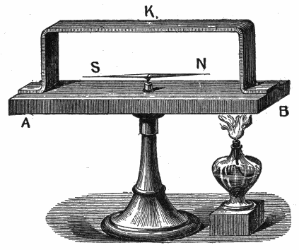
Fig.
88.—The Seebeck effect: If in a complete metallic circuit having junctions of dissimilar metals, the junctions are at different temperatures, then generally a steady current will flow in the circuit as long as the differences of the temperatures of the junction is maintained. To demonstrate this, a piece of copper K bent in the shape seen in the figure, was placed on a block of bismuth A B, carrying a pivoted magnetic needle N S; as soon as the equality of temperatures was altered by either heating or cooling one of the junctions of the two metals, the needle indicated a current which continued to flow as long as the difference of temperature was maintained at the junctions. The movement of the needle indicated the direction in which the current flowed. If, for instance, the north junction B were heated, the N pole moved eastwards, showing that at the heated junction the current flows from the bismuth to the copper, at the cold junction from the copper to the bismuth.
When matter in motion is stopped by friction, the energy of its motion is converted into heat by the friction thus causing the matter to come to rest. Similarly, when electricity in motion, that is, an electric current is stopped by resistance, the energy of its flow is transformed into heat by the resistance of the circuit.
If the terminals of a battery be joined by a short thick wire of low resistance, most of the heat will be developed in the battery, whereas, if a thin wire of high resistance be used it will become hot, while the battery itself will remain comparatively cool.
To investigate the development of heat by a current, Joule and Lenz used instruments on the principle of fig. 87, in which a thin wire joined to two stout conductors is enclosed within a glass vessel containing alcohol, into which is placed a thermometer. The resistance of the wire being known, its relation to the other resistances can be calculated. Joule found that the number of heat units developed in a conductor is proportional to:
1. The resistance;
2. The square of the current strength;
3. The time that the current lasts.
Joules’ law may be stated as follows:
The heat generated in a conductor by an electric current is proportional to the resistance of the conductor, the time during which the current flows, and the square of the strength of the current.
The quantity of heat in calories may be calculated by use of the equation,
calories per second = volts × amperes × .24. (1)
The total number of calories H developed in t seconds will be given by
H = P.D. × C × t × .24. (2)
EXAMPLE—If a current of 10 amperes flows in a wire whose terminals are at a potential difference of 12 volts, how much heat will be developed in 5 minutes?
Substituting in equation (2):
10 × 12 × (60 × 5) × .24 = 8640 calories.
Since by Ohm’s Law potential difference = I × R substituting IR for P.D. in (2)
H = I2 R × t × .24
Use of Heat from Electric Current.—In the transmission of electricity from place to place, it is very desirable that none of the energy be expended in heating the conductor. Hence copper wires of the proper size must be used.
In wiring a building for electric lights, the insurance rules require that the wires be of a certain size and that they be put up in a certain manner. Otherwise they will not insure a building against fire.
It is often desirable, however, to use the electric current for the purpose of producing heat. The carbons of the arc and incandescent lamps are intensely heated that they may produce light. Coils of German silver wire or other high resistance wire are heated by the passage of a current through them. In this manner the electric stove is made.
Soldering coppers, smoothing irons, and baking ovens are heated in a similar manner.
Magnetic Effect.—An electric current flowing in a wire causes it to be surrounded by a magnetic field, which consists of lines of force encircling the wire. The field is strongest near the wire and diminishes gradually in strength at increasing distances therefrom. The presence of this magnetic field is shown by various experiments and the subject is fully explained in chapter IX on magnetism.
Chemical Effect.—Pats van Trostwyk (1789) pointed out that an electric discharge was capable of decomposing water; to show this he used gold wires, which he allowed to dip in water, connecting one of them with the inner, and another with the outer coating of a Leyden jar, and passing the discharge through the water. The gas bubbles collected proved to consist of oxygen and hydrogen gas.
Nicholson and Carlisle (1800) dipped a copper wire which was connected with one of the poles of a voltaic pile into a drop of water, which happened to be on the plate connected with the other pole; gas bubbles appeared, and the drop of water became smaller and smaller.
This experiment was repeated in a somewhat different manner, the brass wires from a pile being brought under a tube filled with water and closed at the top. Gas bubbles were produced by the wire in connection with the negative pole of the pile, and the water was observed to diminish gradually. At the positive wire, on the contrary, no gas came off, but the metal lost its metallic lustre, became dark, and finally crumbled away. The gas which had collected in the tube proved to be hydrogen; while on examining the black mass it was found that the constituents of brass, viz., copper and zinc, had become oxidized.
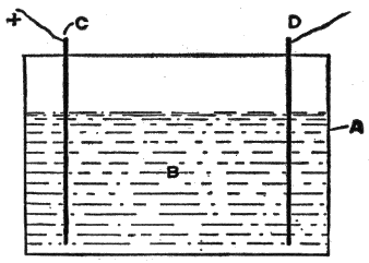
Fig.
89.—An electrolytic cell. The parts are: A, cell; B, electrolyte; C, positive electrode or cathode; D, negative electrode or cathode.
Electrolysis.—Electric analysis or more briefly electrolysis was the term applied by Faraday to the process of decomposing a liquid by the passage of a current of electricity through it.
The vessel containing the liquid is known as an electrolytic cell. In fig. 89, A is the cell, which may be of glass or of any other suitable material, and B is the liquid which is to be electrolyzed. Current enters by the positive electrode C, also known as the anode, traverses the liquid, and leaves by the negative electrode, or cathode, D.
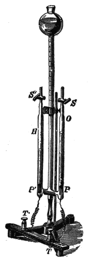
Fig.
90.—Modern apparatus for decomposing water by electrolysis. Platinum electrodes P and P′ are placed at the bottom of two upright tubes O and H, and are connected to the terminals T and T′ by platinum wires, which are fused through the glass of the tubes. These tubes have glass stop cocks S and S′ at their upper ends, and at their lower ends are connected by a short glass tube, from the center of which rises the large central tube which expands with a bulb at its upper end, which is open at the top. The three tubes can be filled with acidulated water from the central tube, the previously contained air being allowed to escape through the stop cocks, which are afterwards closed. If it be so filled, and the terminal T be attached to the positive and T′ to the negative pole of a suitable battery, bubbles of gas will be observed to rise from the plates P and P′, and finding their way to the top of the respective tubes, will displace the liquid, which will be driven into the open central tube. The gas rising from the anode P is oxygen (O), and that rising from the cathode P′ is hydrogen (H). If the tubes are graduated, the latter will be found to occupy about twice the volume of the former. The proportion is theoretically 2 to 1; however, on account of the different solubilities of the two gases in water, oxygen being the more soluble of the two, is deficient in quantity.
The passage of current through the water splits up its molecules into their constituent atoms of oxygen and hydrogen, the former being given off in bubbles at the anode, and the latter at the cathode.
When current is passed through a solution of copper sulphate between platinum electrodes, the liquid is decomposed, atoms of copper being deposited at the cathode, bubbles of oxygen being given off at the anode, and sulphuric acid being formed in the liquid, which latter becomes more and more acid as the copper is withdrawn.
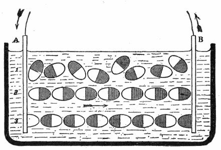
Fig.
91.—Grotthuss’ theory of electrolysis. Grotthuss in (1806), announced his theory that the molecules in an electrolyte have their individual electro-positive and electro-negative atoms charged positively and negatively respectively. In an ordinary liquid, for instance in water, the molecules are arranged indifferently, like row 1, with their positive and negative ends pointing in all directions. When the charged plates A and B connected to the + and - poles of a battery are inserted in the water, the molecules under the action of the laws of electrostatic action turn as shown in row 2, so that all the hydrogen or shaded ends (+) are turned towards the (-) plate B and all the oxygen or unshaded ends (-) towards the (+) plate A. All along the row the electrical forces are supposed to tear the molecules asunder, depositing H on B and O on A. The atoms in the middle of the liquid, however, recombine, for the hydrogen atoms in their journey towards B meet the oxygen atoms travelling in the opposite direction, and we get the state of affairs represented in row 3. The next step is to rotate once more the atoms into the positions shown in row 2, and so on. In this way the theory accounts for the products only appearing at the electrodes and not in the body of the liquid.
If, however, the anode be of copper instead of platinum, no sulphuric acid will be formed, neither will oxygen be given off at the anode. As copper is deposited at the cathode, an equal quantity will be dissolved at the anode, so that the original constitution of the liquid is maintained.
The atoms separated from each other by the electric current were called ions by Faraday; those going to the anode being anions, and those going to the cathode being kathions.
Anions are generally regarded as electro-negative, because they move as if attracted to the positive electrode, while kathions are regarded as electro-positive.
In order to explain the transfer of electricity and the transfer of matter through the electrolyte, Grotthuss put forward the hypothesis that when two metal plates at different potentials are placed in a cell, the effect produced in the liquid is that the molecules of the liquid arrange themselves in innumerable chains, as shown in fig. 91, in which every molecule has its atoms pointing in a certain direction, the electro-positive atom being attracted towards the cathode and the electro-negative towards the anode. An interchange then takes place all along the line, the free atoms appearing at the electrodes, and every atom discharging a minute charge of electricity upon the electrode at which it is liberated.
Electro-chemical Series.—This is an arrangement of the metals in a series in such a manner that the most electro-positive is at one end and the most electro-negative at the other.
The order of the metals varies with the electrolyte in which the metals are tested.
The following table shows such series for the most common metals, in three different solutions:
Sulphuric acid.Hydrochloric acid.Caustic potash.
ZincZincZinc
CadmiumCadmiumTin
TinTinCadmium
LeadLeadAntimony
IronIronLead
NickelCopperBismuth
BismuthBismuthIron
AntimonyNickelCopper
CopperSilverNickel
SilverAntimonySilver
Gold
Platinum
Faraday stated several laws of electrolysis, as follows:
1. The quantity of an ion liberated in a given time is proportional to the quantity of electricity that has passed through the voltameter[10] in that time.
2. The quantity of an ion liberated in a voltameter is proportional to the electro-chemical equivalent of the ion.
3. The quantity of an ion liberated is equal to the electro-chemical equivalent of the ion multiplied by the total quantity of electricity that has passed.
Electric Osmose.—Porret observed that if a strong current be led into certain liquids as if to electrolyze them, a porous partition being placed between the electrodes, the current mechanically carries part of the liquid through the porous diaphragm, so that the liquid is forced to a higher level on one side than on the other. This phenomenon is known as electric osmose.
Electric Distillation.—Closely connected with the preceding phenomenon is that of the electric distillation of liquids. It was noticed by Beccaria that an electrified liquid evaporates more rapidly than one not electrified.
Gernez has recently shown that in a bent closed tube, containing two portions of liquid, one of which is made highly + and the other highly -, the liquid passes over from + to -. This apparent distillation is not due to difference of temperature, nor does it depend on the extent of surface exposed, but is effected by a slow creeping of the liquid along the interior surface of the glass tubes. Bad conductors, such as turpentine, do not thus pass over.
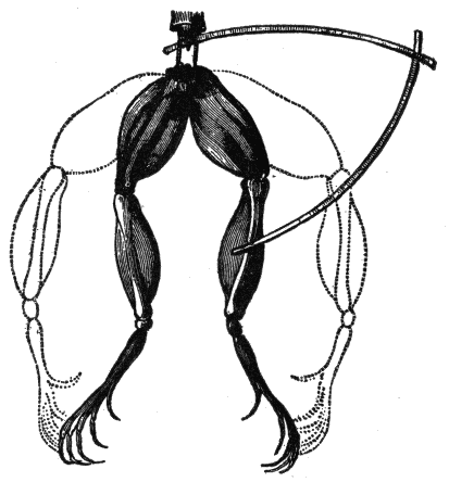
Fig.
92.—Effect of the electric current on a frog’s legs; discovered in 1678 by Galvani.
Muscular Contractions.—It was discovered in 1678 that when a portion of muscle of a frog’s leg, hanging by a thread of nerve bound with a silver wire, was held over a copper support so that both nerve and wire touched the copper, the muscle immediately contracted.
More than a century later Galvani’s attention was drawn to the subject by his observation of spasmodic contractions in the legs of freshly killed frogs under the influence of the “return shock” experienced every time a neighboring electric machine was discharged.
The limbs of the frog, prepared as directed by Galvani, are shown in fig. 92. After the animal has been killed the hind limbs are detached and skinned; the crural nerves and their attachments to the lumbar vertebrae remaining. For some hours after death the limbs retain their contractile power. The frog’s limbs thus prepared form an excessively delicate galvanoscope.
Electroplating.—This is the process of depositing a layer or coating of a rarer metal upon the surface of a baser, or of a metal upon any conducting surface, by electrolysis.
The electric current used may be obtained from a battery or other source. The battery has its positive plate connected to a rod extending across a trough or tank containing the plating bath.
Suspended from the rod are anodes of gold, silver, or copper or whatever metal from which a deposit is desired. The other plates of the battery or the negative elements, are connected with another rod across the trough, to which are suspended the articles to be plated.
Electrotyping.—This is the process by which, type, wood cuts, etc., are reproduced in copper by the process of electroplating. A mould is first made of the set type in wax; this mould is next coated with black lead to give it a metallic surface, as the wax is an insulator; the mould is then subjected to the process of electro deposition, resulting in the formation of a film of copper on the prepared surface.
The copper shell is removed from the mould by applying hot water; the shell is then backed up with electrotype metal to render it strong enough for use.
Almost all the illustrations in this book, for example, are printed from electrotype copies, and not from the original wood blocks, which would not wear so well.