Chapter XI · INDUCTION COILS
Reading edition
The induction coil has always been a popular piece of apparatus with those interested in electrical science; the experiments which can be performed with its aid are very numerous. It is of considerable importance, especially in its application to such useful purposes as X ray work, wireless telegraphy and ignition for gas engines. The latter has caused manufacturers to give much attention to the development of the induction coil, resulting in many refinements of design and construction.
Induction coils may be divided into two general classes:
1. Primary coils;
2. Secondary coils.
The subject of electromagnetic induction has been fully explained in chapter X, but it may be said, with special reference to induction coils, that the operation of the two classes just mentioned is respectively due to:
1. Self-induction;
2. Mutual induction.
Self-induction.—This is the property of an electric current by virtue of which it tends to resist any change in its rate of flow. It is sometimes spoken of as electromagnetic inertia and is analogous to the mechanical inertia of matter.
Self-induction is due to the action of the current upon itself during variations in strength. It becomes especially marked in a coil of wire, in which the adjacent turns act inductively upon each other upon the principle of mutual induction arising between two separate adjacent circuits. Self-induction manifests itself by giving “momentum” to the current so that it cannot be instantly stopped when the circuit is broken, the result being a bright spark at the moment of breaking the circuit. On account of this spark a primary induction coil is used in low tension or “make and break” ignition systems.
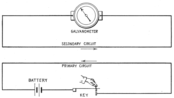
Fig.
135.—Diagram illustrating the action of mutual induction between two circuits; the one including a source of electrical energy and a switch; the other including a galvanometer, but having no cell or other electrical source. During the increase or decrease in the strength of the current as on closing or opening the key a current is
induced
in the secondary circuit in a direction opposite to that of the primary current as indicated by the arrows.
In a single circuit, consisting of a straight wire and a parallel return wire there is little or no self-induction. When a circuit containing a primary induction coil and a battery is closed there is no spark because at the instant of closing the circuit the current is at rest and on account of self-induction the current cannot at once rise to its full value.
Mutual Induction.—This is a particular case of electromagnetic induction in which the magnetic field producing an electromotive force in a circuit is due to the current in a neighboring circuit.
The effect of mutual induction may be explained with the aid of fig. 135. If, as illustrated, a circuit including a battery and a switch, be placed near another circuit, formed by connecting the two terminals of a galvanometer by a wire, it will be found that whenever the first circuit, 1, is closed by the switch, allowing a current to pass in a given direction, a momentary current will be induced in the second circuit, 2, as shown by the galvanometer. A similar result will follow on the opening of the battery circuit, the difference being that the momentary induced current occurring at closure moves in a direction opposite to that in the battery circuit, while the momentary current at opening moves in the same direction.
Currents, besides being induced in circuit 2 at make or break of circuit 1, are also induced when the current in 1 is fluctuating in intensity.
The most marked results are observed when the make or break is sudden, the action being strongest at the break of the current in 1.
The inductive effect of the current in the arrangement shown in fig. 135 is very weak.
Ques. What name is given to circuit 1?
Ans. The primary circuit.
Ques. What name is given to circuit 2?
Ans. The secondary circuit.
Ques. What names are given respectively to the currents in circuits 1 and 2?
Ans. The primary and secondary or induced currents.
Primary Induction Coils.—These represent the simplest form of coil, and are used chiefly in low tension ignition to intensify the spark when a battery forms the current source.
A primary coil consists of a long iron core wound with a considerable length of low resistance insulated copper wire, the length of the core and the number of turns of the insulated wire winding determining the efficiency. The effect of the iron core is to increase the self-induction.
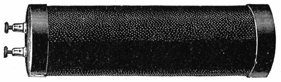
Fig.
136.—Primary induction coil as used for low tension ignition. Coils of this type are made in a great variety of form and size. Ordinarily the winding consists of about six convolutions of No. 14 copper wire. The winding is usually covered and the ends capped with ebonite heads so that the core wires are not exposed.
The spark produced, as previously explained, is due to self-induction, and it should be remembered that in the operation of the coil, the spark occurs at the instant of breaking the circuit, not at the instant of making.
Secondary Induction Coils.—The arrangement shown in fig. 137, may be considered as a very simple or rudimentary form of secondary induction coil. In the actual coil, the primary and secondary circuits (corresponding to 1 and 2 in fig. 135) are made up of coils of insulated wire, as shown in fig. 143, the primary coil P, being wound over a core C and the secondary coil S being wound over the primary.
The one property of such an arrangement that makes it of great value for most purposes is that the voltage of the induced currents may be increased or diminished to any extent depending on the relation between the number of turns in the primary and secondary winding.
This relation may be expressed in the following rule:
The voltage of the secondary current is (approximately) to the voltage of the primary current as the number of turns of the secondary winding is to the number of turns of the primary winding.
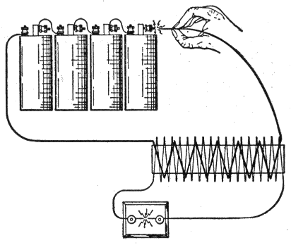
Fig.
137.—Production of spark with plain coil. Connect the ends or leads of the secondary winding to fixed insulators and bend the ends so they are from one-sixteenth to one-eighth inch apart. Connect one end of the primary winding to an electric battery, and with the other lead of the primary winding brush against the other terminal of the battery, as indicated. When the contact is broken there will be a spark both at the point of rupture in the primary circuit and at the gap. An electric impulse is also induced in the secondary circuit when the primary circuit is closed and the current flowing in it gradually rises to its maximum value, but this impulse is too feeble to cause a spark to jump across the gap. Only the impulse induced in the secondary during the dying out of the current in the primary is utilized.
For instance, if the voltage of the primary current be 5 volts, the primary winding have 10 turns and the secondary 100 turns, then
Secondary voltage: 5 :: 100 : 10 from which
Secondary voltage = 50 volts (approximately)
The watts in each circuit are approximately the same; hence: if, for instance, the current strength in the primary circuit be 5 amperes, the watts in primary circuit are 5 × 5 = 25. Accordingly, for the secondary circuit the current strength is:
25 watts / 50 volts = 1⁄2 ampere (approximately)
From this, it is seen that where the voltage is raised in the secondary circuit, the current flow is small as compared to that in the primary circuit; therefore, heavy wire is used in the primary winding and fine wire in the secondary, as indicated in figs. 137 and 143.
For most purposes a very much higher secondary voltage is required than in the example just given.
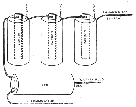
Fig.
138.—Diagram of battery and coil connections for jump spark ignition as applied to a motor cycle. Coils are usually plainly labeled with the abbreviations: “Bat.,” “Pri.,” “Sec.,” indicating that the wires are to be connected to the battery, the primary circuit or contact maker, and the spark plug. The battery and primary wires being for the low tension circuit are easily distinguished from the secondary wire by the small amount of insulation surrounding them.
Secondary induction coils may be divided into three general classes:
1. Plain coils;
2. Vibrator coils;
3. Condenser coils.
The plain coil gives but one spark when the primary circuit is made and broken, while the vibrator coil gives a series of sparks following each other in rapid succession.
Plain Secondary Induction Coils.—Coils of this class are very simple and consist of:
1. Core;
2. Primary winding;
3. Secondary winding.
The construction of a plain coil, such as would be suitable for ignition service, is about as follows:
The core is made of soft annealed iron wires (No. 20 B and S gauge) from one-half to three-quarters of an inch in diameter and about six inches long. Over this core is slipped a spool of insulating material (hard rubber or composition), on which is wound first the primary winding of the coil, which consists of several layers of about No. 18 B and S gauge silk insulated magnet wire.
After the primary winding has been wound over the insulated core, and the ends have been properly brought out through the heads of the spool to be connected to binding posts thereon, a layer of insulating material is applied over the primary wire, and the secondary winding is then wound on.
The wire for the secondary winding consists of about No. 36 B and S gauge silk covered magnet wire, the amount used varying considerably, depending on the desired voltage of the secondary current.
When all the wire has been wound on, the ends are brought out to the binding posts, the coil is soaked in shellac dissolved in alcohol and baked, or in melted paraffin or a paraffin compound, and allowed to cool. It is then placed in either a cylindrical hard rubber shell or in a hard wood box.
The proportions of such coils vary greatly; for motor cycle use they are made long and of small diameter (10×21⁄2 inches for instance), while for some other purposes short and thick coils are found more convenient.
Ques. How may the coil just described be connected for demonstrating purposes?
Ans. Connect the ends of the secondary winding to fixed insulators and bend the ends so they are about 1⁄8 inch or less apart. Connect one end of the primary winding to a battery and brush the other end of the primary winding against the other terminal of the battery as indicated in fig. 137.
Ques. What happens when the primary circuit is made?
Ans. An electric pressure is induced in the secondary circuit, but of not enough intensity to cause a spark to jump across the air gap.
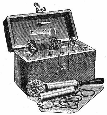
Fig.
139.—A Medical coil with armature and attachments consisting of electrodes, foot place, sponge, induction coil etc. A current of any degree of intensity may be obtained. The currents furnished are: 1, primary, 2, secondary; and 3, primary and secondary combined.
Ques. What happens when the primary circuit is suddenly broken?
Ans. A spark is produced both at the point of break in the primary circuit and at the air gap in the secondary circuit.
Ques. Why is a spark produced at the air gap at break and not at make of the primary current?
Ans. Because when the current is flowing it cannot be stopped instantly on account of self-induction, that is, it acts as though it possessed weight.
If the reader has charge of a gas engine with a make and break ignition system, he will often avoid vexatious delays in locating ignition troubles, if he remember that one of the most important conditions for obtaining a good spark is that the break take place with great rapidity. This, of course, involves that the ignition spring be adjusted to the proper tension.
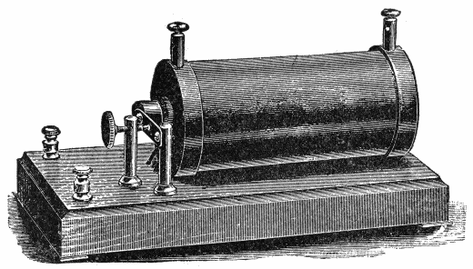
Fig.
140.—Rhumkorff induction coil. A secondary coil with vibrator and condenser; a type generally used in the laboratory. The name Rhumkorff was formerly very widely applied to induction coils for the reason that some of the earliest coils were constructed by Rhumkorff.
Secondary Induction Coils with Vibrator and Condenser.—A plain secondary coil, such as just described, will only give feeble sparks for its size for the following reasons: The inductive effect of the primary winding in the secondary depends as previously explained on the rate at which the current in the primary winding decreases or dies out.
If a strong inductive effect is to be produced in the secondary, the current in the primary must stop suddenly. This is prevented by self-induction in the primary winding, which opposes any change in the current strength. The direct result is that, as the primary circuit is broken, a spark appears at the break, which means that the current continues to flow after the break has occurred, dying down comparatively slowly, hence, the inductive effect on the secondary winding is small.
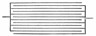
Fig.
141.—Conventional diagram of a condenser. A condenser is a device designed to absorb or hold an electric charge in about the same manner as a vessel will hold a liquid. Every conductor of electricity forms a condenser and its capacity for holding a charge depends upon the extent of its surface. A condenser is therefore made of conductive material formed into such shape as to present the maximum surface for a given amount of material.
The spark at the break in the primary circuit is even larger than that in the secondary circuit, and as this primary spark serves no useful purpose, but, on the contrary, quickly burns away the contact points, such an arrangement is obviously defective.
The vibrator-condenser coil is designed to overcome this trouble and also to give a series of sparks following in rapid succession instead of one.
It should be noted that a series of sparks following each other with considerable rapidity may be obtained with a plain coil by placing a mechanical vibrator in the primary circuit, as used on some motor cycle ignition circuits.
The object of the vibrator, of a vibrator-condenser coil, is to rapidly make and break the primary circuit during the time the primary circuit is closed externally. It consists of a flat steel spring secured at one end, with the other free to vibrate. At a point about midway between its ends, contact is made with the point of an adjusting screw, from which it springs away and returns in vibrating. The points of contact of blade and screw are tipped with platinum. One wire of the primary circuit is connected to the blade and the other to the screw, hence, the circuit is made when the blade is in contact with the screw and broken when it springs away.
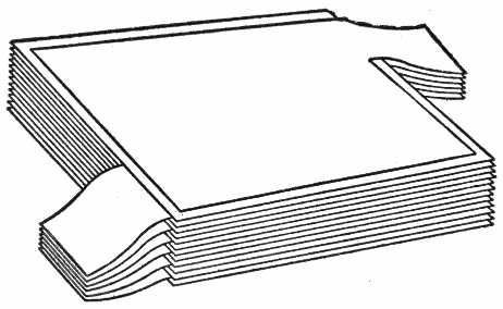
Fig.
142.—Construction of condenser for an induction coil. The conducting material used is tinfoil, of which a large number of sheets are prepared, all cut to the same size. These are placed, one on top of the other, like the pages of a book, with a thin layer of insulating material between, usually two sheets of paraffined paper. Numbering the successive sheets of tinfoil serially, all sheets of even number are connected together and all sheets of odd number are connected together, these connections forming the terminals of the condenser. The condenser is then connected across the break in the primary circuit.
A condenser is used to absorb the self-induced current of the primary winding and thus prevent it opposing the rapid fall of the primary current.
Every conductor of electricity forms a condenser and its capacity for absorbing a charge depends upon the extent of its surface. Hence, a condenser is constructed of conductive material so arranged as to present the greatest surface for a given amount of material.
The usual form of condenser for induction coils as shown in figs. 141 and 142 is composed of a number of layers of tin foil separated by paraffin paper, each alternate layer being connected at the ends.
Fig. 143 is a diagram of a vibrator coil. CC represents the core composed of soft iron wires. PP is the primary winding and SS the secondary. There is no connection between these windings and they are carefully insulated. Y is the vibrator or trembler and D the center about which it vibrates. W is a switch used for opening and closing the primary circuit; B, a battery of five cells. The point of adjusting screw A rests against a platinum point R soldered upon the vibrator.
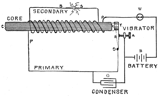
Fig.
143.—Diagram of a vibrator coil. The parts are as follows: A, contact screw; B battery; C, core; D, vibrator terminal; G, condenser; P, primary winding; S, secondary winding; W, switch; Y, vibrator. When the switch is closed, the following cycle of actions take place: 1, the primary current flows and magnetizes core; 2, magnetized core attracts the vibrator and breaks primary circuit; 3, the magnetism vanishes, including a momentary high tension current in the secondary winding; 4, magnetic attraction of the core having ceased, vibrator spring renews contact; 5, primary circuit is again completed and the cycle begins anew.
If the switch W be closed, the electric current generated by the battery B will flow through the primary winding. This will cause the core CC to become magnetized, and the vibrator Y will at once be drawn toward it. This will break the connection at R. The core, being made of soft iron, immediately upon the interruption of the current, will again lose its magnetism, and the vibrator will return to its original position. This again closes the circuit, after which the operation of opening and closing it is repeated with great rapidity so long as the switch W remains closed.
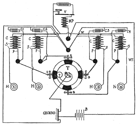
Fig.
144.—Circuit diagram of a master vibrator coil. B, is the battery; C, the unit coils; C1, C2, etc., the condensers; P, the primary windings and S, the secondary windings; H1, H2, etc., the spark plugs; T, the timer; MP, the master primary; V, the vibrator; W, the common primary connection; 1, 2, etc., the stationary contacts of the timer.
The cycle of actions may be briefly stated as follows:
1. A primary current flows and magnetizes the core; 2. The magnetized core attracts the vibrator which breaks the primary circuit; 3. The core loses its magnetism and the vibrator springs back to its original position; 4. The vibrator, by returning to its original position, closes the primary circuit and the cycle begins again.
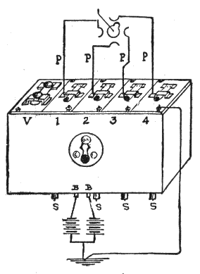
Fig.
145.—The Splitdorf master vibrator coil. As shown in the illustration the several unit coils are indicated by the figures 1, 2, 3, and 4. A fifth unit V at the left contains the master vibrator. The primary wires P connect with the timer and the secondary wires S with the plugs. B B shows the battery connections.
Magnetic Vibrators.—Many types of vibrator are used on induction coils, the most important requirement being that the break occur with great rapidity. In order to render the break as sudden as possible, different expedients have been resorted to, all tending to make the mechanism more complicated, yet having sufficient merit in some cases to warrant their adoption.
In the plain vibrator, the circuit is broken at the instant the spring begins to move, hence, the operation must be comparatively slow.
In order to render the break more abrupt some vibrators have two moving parts, one of which is attracted by the magnetic core of the coil and moved a certain distance before the break is effected. A vibrator of this type is shown in fig. 146 and described under the illustration.
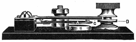
Fig.
146.—A hammer vibrator. When at rest, the upward tension of the spring, which carries the armature A, holds the platinum points in contact and causes the upper spring C, to leave shoulder of adjusting screw D, and rest against the heavy brass plate above it. When the iron core B, attracts the armature A, the downward tension on the upper spring, C, causes the latter to follow the armature down, holding the platinum point in contact, until the end of the upper spring C, strikes the lower shoulder of the adjusting screw, D, which gives it a “hammer break.” The adjusting screw is held firmly in position by a bronze spiral spring under shoulder D.
Vibrator Adjustment.—When a vibrator coil is used, the quality of the spark depends largely upon the proper adjustment of the vibrator. The following general instructions for adjusting a plain vibrator should be carefully noted:
1. Remove entirely the contact adjusting screw. 2. See that the surfaces of the contact points are flat, clean and bright. 3. Adjust the vibrator spring so that the hammer or piece of iron on the end of the vibrator spring stands normally about one-sixteenth of an inch from the end of the coil. 4. Adjust the contact screw until it just touches the platinum contact on the vibrator spring—be sure that it touches, but very lightly. Now start the engine; if it miss at all, tighten up, or screw in the contact screw a trifle further—just a trifle at a time, until the engine will run without missing explosions.
TABLE OF INDUCTION COIL DIMENSIONS.
Length of spark3⁄8 inch1⁄2 inch1 inch2 inches
Size of bobbin ends21⁄8 × 11⁄421⁄2 × 5⁄163 × 3⁄84 × 23⁄4 × 3⁄8
Length of bobbin451⁄261⁄261⁄2
Length and diameter of core41⁄4 × 7⁄166 × 5⁄861⁄2 × 3⁄4
Size of base71⁄4 × 31⁄4 × 11⁄29 × 5 × 2141⁄2 × 6 × 13⁄412 × 71⁄2 × 31⁄4
Size of tinfoil sheets4 × 251⁄2 × 31⁄46 × 46 × 6
Number of tinfoil sheets36404060
Size of paper sheets5 × 361⁄2 × 41⁄49 × 5
Primary coilNo. 18No. 182 layers No. 16, silk covered.2 layers 14 B. W. G., silk covered.
Secondary coil3⁄4 lb. No. 401 lb. No. 4011⁄4 lbs. No. 3821⁄2 lbs. No. 36
TABLE OF SPARKING DISTANCES IN AIR.[13]
Volts.Distance.
(Inches.)
5000.225
10000.47
200001.00
300001.625
350002.00
450002.95
600004.65
700004.85
800007.1
1000009.6
13000012.95
15000015.00
Points Relating to Ignition Coils.—1. Most ignition induction coils or “spark coils” as they are called, have terminals marked “battery,” “ground,” etc., and to short circuit the timer for the purpose of testing the vibrator, it is only necessary to bridge with a screw driver from the “battery” binding post to the “ground” binding post.
2. In adjusting the vibrator of an ignition coil, the latter should not require over one-half ampere of current.
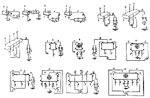
Fig. 147 to 161.—Wiring diagrams showing connections of some standard spark coils. Larger.
3. A half turn of the adjusting screw on a coil will often increase the strength of the current four or five times the original amount, hence, the necessity of carefully adjusting the vibrator. When the adjustment is not properly made it causes, 1, short life of the battery, 2, burned contact points, and 3, poor running of the engine.
4. In adjusting a multi-unit coil, if any misfiring be noticed, hold down one vibrator after another until the faulty one is located, then screw in its contact screw very slightly.
5. The number of cells in the circuit should be proportioned to the design of the coil.
If the coil be described by the maker as a 4 volt coil, it should be worked by two cells of a storage battery or four dry cells. The voltage of the latter will be somewhat higher, but since their internal resistance is also greater, the current delivery will be about the same. Most coils are made to operate on from 4 to 6 volts.
6. It is a mistake to use a higher voltage than that for which the coil is designed, because it does not improve the spark and the contact points of the vibrator will be burned more rapidly, moreover, the life of the battery will be shortened.