Chapter X · ELECTROMAGNETIC INDUCTION
Reading edition
The word induction, introduced by Faraday, has various meanings so far as it relates to electricity. It signifies, in general, phenomena produced in bodies by the influence of other bodies, having no necessary material connection with them.
A body charged with electricity causes or “induces” charges on neighboring bodies. The process in this case is called electrostatic induction.
A magnet induces magnetism in neighboring masses of iron or other magnetic materials by the process of magnetic induction.
Again, a moving magnet induces electric currents in neighboring conductors by the process of electromagnetic induction.
Faraday’s Discovery.—All dynamos of whatever form, are based upon the discovery made by Faraday[11] in 1831, which may be stated as follows:
Electric currents are generated in conductors by moving them in a magnetic field, so as to cut magnetic lines of force.
Ques. What does the expression “cut lines of force” mean?
Ans. A conductor, forming part of an electric circuit, cuts lines of force when it moves across a magnetic field in such manner as to alter the number of magnetic lines of force which are embraced by the circuit.
It is important to clearly understand the meaning of this expression, which will be later explained in more detail.
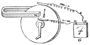
Fig.
126.—Faraday’s dynamo which embodies his discovery in 1831 of
electromagnetic induction
, the principle upon which all dynamos work, as well as induction coils, transformers, and other electrical apparatus.
Faraday’s Machine.—After various experiments, Faraday made his “new electrical machine” as shown in fig. 126. This piece of apparatus is preserved and was shown in perfect action by Prof. S. P. Thompson in a lecture delivered April 11th, 1891, after an interval of sixty years.
It consists of a horse shoe magnet and a copper disc attached to a shaft and supported so as to turn freely. The magnet is so placed that its inter-polar lines of force traverse the disc from side to side. There are two copper brushes, one bears against the shaft, and the other against the circumference of the disc. A handle serves to rotate the disc in the magnetic field.
Now, if the north pole of the magnet be nearest the observer and the disc be rotated clockwise, the current induced in the circuit will flow out at the brush which touches the circumference, and return through the brush at the shaft.
Faraday’s Principle.—The principle deduced from Faraday’s experiment may be stated as follows:
When a conducting circuit is moved in a magnetic field so as to alter the number of lines of force passing through it, a current is induced therein, in a direction at right angles to the direction of the motion, and at right angles also to the direction of the lines of force, and to the right of the lines of force, as viewed from the point from which the motion originated.
Faraday’s principle may be extended as follows to cover all cases of electromagnetic induction:
When a conducting circuit is moved in a magnetic field, so as to alter the number of lines of force passing through it, or when the strength of the field is varied so as to either increase or decrease the number of lines of force passing through the circuit, a current is induced therein which lasts only during the interval of change in the number of lines of force embraced by the circuit.
Ques. Explain just what happens when a current is induced by electromagnetic induction.
Ans. In order to induce an electromotive force by moving a conductor across a uniform magnetic field, it is necessary that the conductor, in its motion, should so cut the magnetic lines as to alter the number of lines of force that pass through the circuit of which the moving conductor forms a part.
Ques. What is the proper name for a “conductor” which moves across the magnetic field?
Ans. An inductor, because it is that part of the electric circuit in which induction takes place.
In the case of a dynamo, an inductor may be either a copper wire or copper bar.
Ques. How may a conducting circuit be moved across a magnetic field without having a current induced therein?
Ans. If a conducting circuit—a wire ring or single coil, for example—be moved in a uniform magnetic field, as shown in fig. 127, so that only the same number of lines of force pass through it, no current will be generated, for since the coil is moved by a motion of translation to another part of the field, as many lines of force will be left behind as are gained in advancing from its first to its second position.
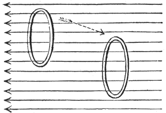
Fig.
127.—Electromagnetic induction: In order to induce a current by electromagnetic induction, a conductor must be so moved through a magnetic field
that the number of lines of force passing through it (that is, embraced) are altered
. If a coil be given a simple motion of translation in a uniform magnetic field as indicated in the figure, no current will be induced
because the number of lines of force passing through it are not changed
, that is, during the movement as many lines are lost as are gained.
Ques. Describe another movement by which no current will be induced.
Ans. If the coil be merely rotated on itself around a central axis, that is, like a fly wheel rotating around a shaft, the number of lines of force passing through the coil will not be altered, hence no current will be generated.
Ques. State the essential condition for current induction in a uniform field.
Ans. The coil in which a current is to be induced, must be tilted in its motion across the uniform field, or rotated around any axis in its plane as in fig. 128, so as to alter the number of lines of force which pass through it.
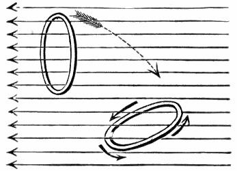
Fig.
128.—Electromagnetic induction: If a coil be given a motion of rotation from any point within its own plane so that it passes through a uniform magnetic field, a current will be induced in the coil
because the number of lines of force passing through it is altered
.
Ques. In what direction will the current flow in the coil, fig. 128?
Ans. The current induced in the coil will flow around it in a clockwise direction (as observed by looking along the magnetic field in the direction in which the magnetic lines run) if the effect of the movement be to diminish the number of lines of force that pass through the coil. The current will flow in the opposite direction, (counter-clockwise) if the movement be such as to increase the number of intercepted lines of force.
Ques. If the magnetic field be not uniform, as in fig. 129, what will be the result?
Ans. The effect of moving the coil by a simple motion of translation from a dense region of the field to one less dense, or vice versa, will be to induce a current because in either case, the number of lines of force passing through the coil is altered.[12]
Laws of Electromagnetic Induction.—There are certain laws of electromagnetic induction which, on account of the importance of the subject, it is well to carefully consider. The facts presented in the preceding paragraphs are embodied in the following fundamental laws:
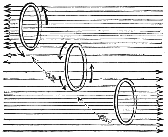
Fig.
129.—Electromagnetic induction: If a coil be given a simple motion of translation in a non-uniform or variable magnetic field, a current will be induced in the coil, whether the motion be from the dense to the less dense region of the field or the reverse,
because the number of lines of force passing through the coil is altered
.
1. To induce a current in a circuit, there must be a relative motion between the circuit and a magnetic field, of such a kind as to alter the number of magnetic lines embraced in the circuit.
2. The electromotive force induced in a circuit is proportional to the rate of increase or decrease in the number of magnetic lines embraced by the circuit.
For instance, if n equal the number of magnetic lines embraced by the circuit at the beginning of the movement, and n′ the number embraced after a very short interval of time t, then
the average induced electromotive force = (n - n′) / t
It would require the cutting of 100,000,000 lines per second to produce an electromotive force equal to that of one Daniell cell.
The unit of electromotive force, called the volt, is the electric pressure produced by cutting 100,000,000 lines per second, usually expressed 108.
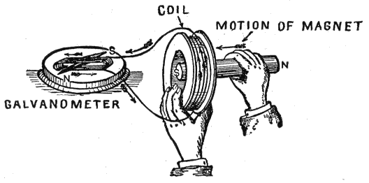
Fig.
130.—Experiment illustrating Lenz’s law which states that in all cases of electromagnetic induction,
the direction of the induced current is such as to tend to stop the motion producing it
. In the experiment, in order to produce the induced current, energy must be expended in bringing the magnet to the coil and in taking it away, which is in accordance with the law of conservation of energy.
3. By joining in series a number of conductors or coils moving in a magnetic field, the electromotive forces in the separate parts are added together.
The reason for this is apparent by considering a coil of wire having several turns and moving in a magnetic field so as to cut magnetic lines. During the movement, the lines cut by the first turn are successively cut by all the other turns of the coil, hence, the total number of lines cut is equal to the number cut by a single turn multiplied by the number of turns. The electromotive forces therefore of the separate turns are added.
EXAMPLE—If a coil of wire of 50 turns cut 100,000 lines in 1⁄100 of a second, what will be the induced voltage?
The number of lines cut per second per turn of the coil is
100,000 × 100 = 10,000,000.
The total number of lines cut by the coil of 50 turns is
10,000,000 × 50 = 500,000,000.
which will induce a pressure of
500,000,000 ÷ 108 = 5 volts.
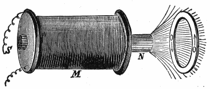
Fig.
131.—Experiment illustrating Lenz’s law. If a copper ring be held in front of an ordinary electromagnet, and the current circulating through the coil of the magnet be in such a direction as to magnetize the core as indicated by the letters S N, then as the current increases in the coil more and more of the lines of force proceeding from N pass through the ring O O from left to right. While the field is thus increasing currents will be induced in the copper ring in the direction indicated by the arrows, such currents tending to set up a field that would pass through the ring from right to left, and would therefore
retard
the growth of the field due to the electromagnet M.
4. A decrease in the number of magnetic lines which pass through a circuit induces a current around the circuit in the positive direction.
The term positive direction is understood to be the direction along which a free N pole would tend to move.
5. An increase in the number of magnetic lines which pass through a circuit induces a current in the negative direction around the circuit.
The reason for the change of direction of the current for decrease or increase in the number of lines cut, as stated in the fourth and fifth laws, will be seen by aid of the formula given under the second law, viz:
electromotive force = (n - n′)/t (1)
but by Ohm’s law
current = electromotive force / resistance or, I = E/R (2)
Substituting (1) in (2)
current = ((n - n′)/t)/R or, (n - n′)/(Rt) (3)
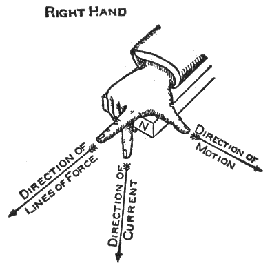
Fig.
132.—Fleming’s rule for direction of induced current. Extend the thumb, forefinger and middle finger of the right hand so that each will be at right angles to the other two. Place the hand in such position that the thumb will point in the direction in which the conductor moves, the forefinger in the direction of the lines of force (N to S), then will the middle finger point in the direction in which the induced current flows.
Now in equation (3) if there be a decrease in the number of lines cut n′ will be less than n hence the current will be positive (+); again, if the lines increase n′ will be greater than n, which will give a minus value, that is, the current will be negative or in a reverse direction.
6. The approach and recession of a conductor from a magnet pole will yield currents alternating in direction.
Since the strength of the field depends on the proximity to the pole, the approach and recession of a conductor involve an increase and decrease in the rate of cutting of magnetic lines, hence a reversal of current.
7. The more rapid the motion, the higher will be the induced electromotive force.
In other words, the greater the number of lines cut per unit of time, the higher will be the voltage.
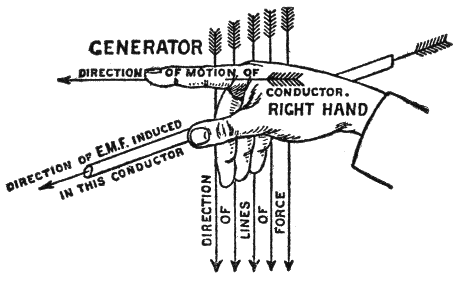
Fig.
133.—A rule for direction of induced current which, in some cases, is more conveniently applied than Fleming’s rule: Hold the thumb, forefinger and remaining fingers of the right hand at right angles to each other; place the hand in such position that the forefinger points in the direction of motion of the conductor, the three fingers in the direction of the lines of force, then will the thumb point in the direction of the induced current.
8. Lenz’s law. The direction of the induced current is always such that its magnetic field opposes the motion which produces it.
This is illustrated in figs. 130 and 131.
Rules for Direction of Induced Current.—There are a number of rules to quickly determine the direction of an induced current, when the direction of the lines of force, and motion of the conductor are known. The first rule here given was devised by Fleming and is very useful. It is sometimes called the “dynamo rule.”
Fleming’s Rule.—If the forefinger of the right hand be pointed in the direction of the magnetic lines, and the thumb (at right angles to the forefinger) be turned in the direction of the motion of the conductor, then will the middle finger, bent at right angles to both thumb and forefinger, show the direction of the induced current.
The application of this rule is shown in fig. 132. Here the right hand is so placed at the north pole of a magnet, that the forefinger points in the direction of the magnetic lines; the thumb in the direction of motion of the conductor; the middle finger pointed at right angles to the thumb and forefinger indicates the direction of the current induced in the conductor.
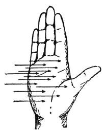
Fig.
134.—The palm rule for direction of induced current: If the palm of the right hand be held against the direction of the lines of force, the thumb in the direction of the motion, then the fingers will point in the direction of the induced current.
Ampere’s Rule.—If a man could swim in a conductor with the current, then the north seeking (+) pole of a magnetic needle placed directly ahead of him, will be deflected to the left, while the south seeking (-) pole will be urged to the right.
For certain particular cases in which a fixed magnet pole acts on a movable circuit, the following converse to Ampere’s rule will be found useful: If a man swim in the wire with the current, and turn so as to look along the direction of the lines of force of the pole (that is, as the lines of force run, from the pole if it be north seeking, toward the pole if it be south seeking), then he and the conducting wire with him will be urged toward his left.
The palm rule.—If the palm of the right hand be held facing or against the lines of force, and the thumb in the direction of the motion, then will the fingers point in the direction of the induced current.
Self-induction.—This term signifies the property of an electric current by virtue of which it tends to resist any change of value. Self-induction is sometimes spoken of as electromagnetic inertia, and is analogous to the mechanical inertia of matter.
It is on account of self-induction of the induced currents in the armature winding of a dynamo, that sparks appear at the brushes when the latter are not properly adjusted, hence the importance of clearly understanding the nature of this peculiar property of the current.
Self-induction is fully explained in the chapter following.