Chapter XIV · THE DYNAMO: CURRENT COMMUTATION
Reading edition
How the Dynamo Produces Direct Current: The Commutator.—The essential difference between an alternator and a dynamo is that the alternator delivers alternating current to the external circuit while the dynamo delivers direct current. In both machines, as before stated, alternating currents are induced in the armature, but the kind of current delivered to the external circuit depends on the manner in which the armature currents are collected.
In the case of an alternator, the method is quite simple. As previously explained, each end of the loop is connected with an insulated collector ring carried by the shaft, the current being collected by means of brushes which bear against the rings. This principle, rather than the actual construction, is shown in the preceding illustrations. Its important point, as distinguished from other methods of collecting the current, is that each end of the loop is always in connection with the same brush.
Ques. How is direct current obtained in a dynamo?
Ans. A form of switch called the commutator is placed between the armature and the external circuit and so arranged that it will reverse the connections with the external circuit at the instant of each reversal of current in the armature.
Ques. How is a commutator constructed?
Ans. It consists of a series of copper bars or segments arranged side by side forming a cylinder, and insulated from each other by sheets of mica or other insulating material.
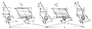
Figs. 174 to 178.—Commutation of the current. Larger.
Ques. Where is the commutator placed?
Ans. It is attached to the shaft at the front end of the armature.
Ques. What are inductors?
Ans. The insulated wires wound on the armature core, and in which the electric current is induced.
Ques. How are the inductors connected to the commutator?
Ans. The ends of each conducting loop or coil must be connected with the commutator segments in a certain order to correspond with the type of winding.
Ques. Explain in detail how direct current is obtained in a dynamo.
Figs.
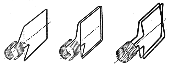
179 to 181.—Elementary dynamo armatures. Fig. 1, single turn loop; fig. 2, coil of two turns
in series
; fig. 3, coil of two turns
in parallel
. In operation the amplitude or maximum pressure induced with the two turn coil, fig. 180, is double that of a single turn loop, fig. 179. In fig. 180, the pressure is double that induced in fig. 181, while the amount of current generated with series turns, fig. 180, is only half that generated with turns in parallel fig. 181.
Ans. It will be easily seen by the aid of a series of illustrations just how the alternating armature currents are transformed into direct current. Figs. 174 to 178 show, in several positions, a single loop of wire with its ends joined to a commutator; the latter has only two segments, one for each end of the loop. In fig. 174 the loop is shown in the vertical position, and it should be noted that the division between the two segments forming the commutator is in the same plane as the loop. When the loop is in the vertical position, as shown in fig. 174, brush M is in contact with segment F, and S with G. As the armature rotates, the current flows for one half revolution in the direction A B, through segment F and out to the external circuit through brush M as shown in figs. 174 and 175, returning through brush S and segment G. At the beginning of the second half of the revolution, fig. 176, the current in the loop reverses and flows in the opposite direction B A as indicated by the arrows. At this instant, however, the brushes M and S pass out of contact with segments F and G, and come into contact with G and F respectively; that is, M leaves F and contacts with G, while S leaves G and contacts with F. The effect of this is to reverse the connections with the external circuit at the instant the alternation or reversal of current in the armature takes place, thus keeping the current in the external circuit in the same direction.
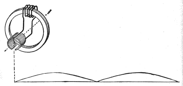
Fig.
182.—Gramme ring armature with one coil, and characteristic sine curve below. With one coil as shown, there are two pulsations of the current per revolution of the armature.
Ques. How is this indicated by the sine curve?
Ans. The sine curve, instead of falling below the axis, as in figs. 169 to 173, again rises as in the first half of the period, that is G′H′I′ is identical with E′F′G′.
Ques. Is the direct current indicated by the sine curve in figs. 174 to 178 continuous?
Ans. No; it is properly described as a pulsating current, or one, constant in direction, but periodically varying in intensity so as to progress in a series of throbbings or pulsations instead of with uniform strength.
Ques. What is generally understood by the word “continuous” as applied to the current obtained from a dynamo?
Ans. It is usually accepted as meaning a steady or non-pulsating direct current; one that has a uniform pressure and constant direction of flow as opposed to an alternating current.
Ques. Is a continuous current ever obtained with a dynamo?
Ans. No.
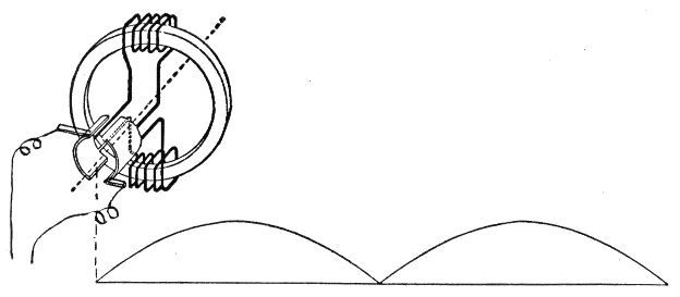
Fig.
183.—Gramme ring armature with two coils placed 180° apart. This arrangement gives double the pressure of the one coil armature, fig. 182.
It should be clearly understood at the outset that it is impossible to obtain a continuous current with a dynamo. The so-called continuous current which it is said to produce is in reality a pulsating current, but with pulsations so minute and following each other with such rapidity that the current is practically continuous, and as such is generally called continuous.
Ques. How is the so-called continuous current produced by a dynamo?
Ans. In order to obtain a large number of small pulsations per revolution of the armature instead of two large pulsations, as with the single loop armature, the latter must be replaced by one having a great number of loops properly connected to commutator segments and so arranged that the successive loops begin the cycle progressively.
The difficulties encountered in connecting up numerous loops were overcome by Gramme, who, in 1871 invented a “ring” armature. His method consists in winding a ring with a continuous coil of wire, connections being made at suitable intervals with the commutator.
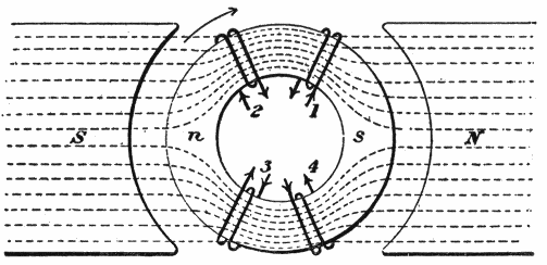
Fig.
184.—Four separate coils wound on ring to illustrate the action of a Gramme ring armature. If the ring be rotated the electromotive forces induced in adjacent coils will be equal and tend to produce currents in opposite directions; hence, if the inner ends be joined, the junctions would be at a higher potential (+ or -) than the loose ends. With proper connections current may be collected at the junctions.
In order to understand the action of such an arrangement, it will be well to first consider four separate coils wound on a ring as shown in fig. 184. These coils are all similar, but at the moment occupy different magnetic positions on the ring. The rotation being clockwise, 1 is about to enter the field adjacent to the north pole, while 2 is emerging from the field in the region of the south pole. Again, 3 is approaching the south pole and 4 receding from the north pole.
Ques. Describe in detail the action of the four coils wound around the ring as in fig. 184.
Ans. According to the laws of electromagnetic induction, pressures are set up at the ends of the coils such as tend to produce currents in the directions indicated by the arrows. Now, assuming the electromotive forces in coils 1 and 2 to be equal, if the adjacent ends be joined, no flow of current will take place, but the junction will be at a higher pressure than the loose ends of the coils and if a wire be attached to this junction, and the necessary circuits completed, a current will flow along the wire outward from the junction. Similarly, if the adjacent ends of coils 3 and 4 be joined, there will be no flow of current, but the junction will be at a lower pressure than the loose ends, and if a wire be attached to the junction and the necessary circuits completed, current will flow from the junction around the coils.
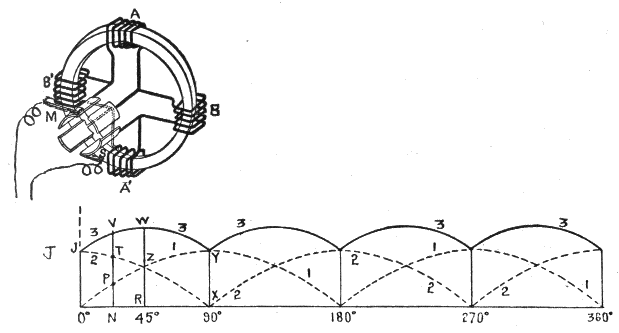
Fig.
185.—Gramme ring armature with four coils. The electromotive force induced in coils A, A′ reaches the zero point at the instant that of coils B, B′ is at a maximum; hence, sine curve No. 1, beginning at zero, and No. 2, at the maximum, show the pressure changes for A, A′ and B, B′, respectively. The summation of these curves gives
the resultant curve
No. 3, showing changes in pressure of current delivered to the external circuit.
Ques. What may be said with respect to the four coil Gramme ring armature shown in fig. 185?
Ans. According to the laws of electromagnetic induction, with the north pole of the field at the left and clockwise rotation, the induced currents flow upward on both sides of the ring, hence, the electromotive forces oppose each other at only two of the junctions, namely: at the one connected to brush M where the pressures on either side are both directed toward the junction and the other at the junction connected to brush S, at which the pressures are both directed from the junction.
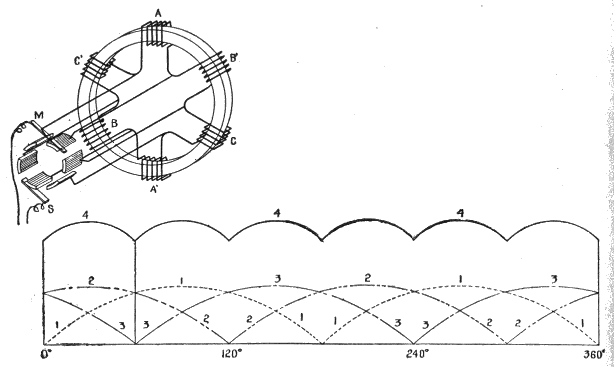
Fig.
186.—Gramme ring armature with six coils. The sine curves 1, 2 and 3, represent the conditions due to coils AA′, BB′ and CC′, respectively, and 4, the resultant pulsations.
It is evident, then, that the pressure at M is higher than at S; that is, M is positive and S negative; consequently, the current flows from M to the external circuit and returns through S.
Ques. In what other way may the four coils of the armature in fig. 185 be regarded?
Ans. They may be considered as two pairs A A′ and B B′, the action of either pair being identical with the two coil armature shown in fig. 183; this, in turn, produces the same effect as the one coil armature of fig. 182, with the exception that the amplitude of the current generated with two coils is twice as great as that with one coil of the same number of turns.
Again considering the action of the four ring coil shown in fig. 185, and starting at the beginning of the revolution, the variation of electromotive force induced in coils AA′ is indicated by the dotted sine curve 1, and of BB′ by dotted curve 2. It will be seen that 1 begins at the axis or line of no pressure, and 2 at maximum pressure.
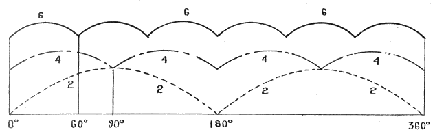
Fig.
187.—The resultant curves of figs. 183, 185 and 186 are here shown for comparison to illustrate the approach to uniform pressure as the number of coils are increased. It should be noted that the number of pulsations per cycle depends on the number of coils, and that as the pulsations increase in number, the variation in pressure decreases.
The two curves overlap each other, and in order to determine the effect of this it is necessary to trace the resultant curve, 3. This is easily done, as the resultant electromotive force induced at any point in the revolution of the armature is equal to the sum of the pressures induced in AA′ and BB′. Thus, at the beginning of the revolution the pressure induced in AA′ is at zero point, and in BB′ at its maximum J, hence, the resultant curve begins at the point J. Again, for any point in the revolution, as N, the height of the resultant curve is equal to NP + NT = NV. For 45° or 1⁄8 revolution, the resultant curve reaches its amplitude, which is equal to 2 × RZ = RW, and at 90° it again reaches its minimum, XY.
Ques. State the conditions upon which the steadiness of the current depends.
Ans. It depends on the number of coils and the manner in which they are connected.
Comparing curves 1 and 3, in fig. 185, it will be noted that with four coils the variation of pressure or amplitude of the pulsations is less than half that obtained with two; moreover, with four coils the number of pulsations per cycle is doubled.
In order to further observe the approach to continuous current obtained by increasing the number of coils, the effect of a six coil armature is shown in fig. 186, the resultant curve being obtained in the same manner as just explained. For comparison, the curves for the three cases of two, four, and six coils are reproduced under each other in fig. 187.
As the number of coils is further increased, the amplitude of the pulsations decreases so that the resultant curve approaches nearer the form of a straight line.
In the actual dynamo there are a great many coils, hence the amplitude of the pulsations is exceedingly small; accordingly, it is customary to speak of the current as “continuous,” although as previously mentioned such is not the case.