VOLUME X SLICE V Fleury, Claude to Foraker (continued 2)
Reading edition
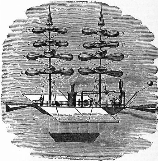
Fig. 37.—De la Landelle’s Flying-machine. m, n, o, p; q, r, s, t, Screws arranged on vertical axes to act vertically upwards. The vertical axes are surmounted by two parachutes, and the body of the machine is furnished with an engine, propeller, rudders and an extensive aeroplane.
Stimulated by the success of his spring models, Ponton d’Amécourt had a small steam model constructed. This model, which was shown at the exhibition of the Aeronautical Society of Great Britain at the Crystal Palace in 1868, consisted of two superposed screws propelled by an engine, the steam for which was generated (for lightness) in an aluminium boiler. This steam model proved a failure, inasmuch as it only lifted a third of its own weight. Fig. 37 embodies de la Landelle’s ideas.
All the models referred to (Cayley’s excepted17) were provided with rigid screws. In 1872 Pénaud discarded the rigid screws in favour of elastic ones, as Pettigrew had done some years before.
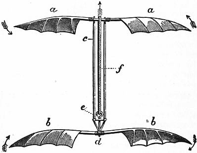
Fig. 38.—Hélicoptère or Screw-Model, by Pénaud.
Pénaud also substituted india-rubber under torsion for the whalebone and clock springs of the smaller models, and the steam of the larger ones. His hélicoptère or screw-model is remarkable for its lightness, simplicity and power. The accompanying sketch will serve to illustrate its construction (fig. 38). It consists of two superposed elastic screws (a a, b b), the upper of which (a a) is fixed in a vertical frame (c), which is pivoted in the central part (d) of the under screw. From the centre of the under screw an axle provided with a hook (e), which performs the part of a crank, projects in an upward direction. Between the hook or crank (e) and the centre of the upper screw (a a), the india-rubber in a state of torsion (f) extends. By fixing the lower screw and turning the upper one a sufficient number of times the requisite degree of torsion and power is obtained. The apparatus when liberated flies into the air sometimes to a height of 50 ft., and gyrates in large circles for a period varying from 15 to 30 seconds.
Pénaud next directed his attention to the construction of a model, to be propelled by a screw and sustained by an elastic aeroplane extending horizontally. Sir George Cayley proposed such a machine in 1810, and W.S. Henson constructed and patented a similar machine in 1842. Several inventors succeeded in making models fly by the aid of aeroplanes and screws, as, e.g. J. Stringfellow in 1847,18 and F. du Temple in 1857. These models flew in a haphazard sort of a way, it being found exceedingly difficult to confer on them the necessary degree of stability fore and aft and laterally. Pénaud succeeded in overcoming the difficulty in question by the invention of what he designated an automatic rudder. This consisted of a small elastic aeroplane placed aft or behind the principal aeroplane which is also elastic. The two elastic aeroplanes extended horizontally and made a slight upward angle with the horizon, the angle made by the smaller aeroplane (the rudder) being slightly in excess of that made by the larger. The motive power was india-rubber in the condition of torsion; the propeller, a screw. The reader will understand the arrangement by a reference to the accompanying drawing (fig. 39).
Models on the aeroplane screw type may be propelled by two screws, one fore and one aft, rotating in opposite directions; and in the event of only one screw being employed it may be placed in front of or behind the aeroplane.
When such a model is wound up and let go it descends about 2 ft., after which, having acquired initial velocity, it rises and flies in a forward direction at a height of from 8 to 10 ft. from the ground for a distance of from 120 to 130 ft. It flies this distance in from 10 to 11 seconds, its mean speed being something like 12 ft. per second. From experiments made with this model, Pénaud calculates that one horse-power would elevate and support 85 ℔
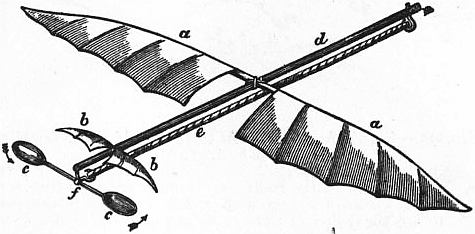
Fig. 39.—Aeroplane Model with Automatic Rudder.
a a, Elastic aeroplane. b b, Automatic rudder. c c, Aerial screw centred at f. d, Frame supporting aeroplane, rudder and screw. e, India-rubber, in a state of torsion, attached to hook or crank at f. By holding the aeroplane (a a) and turning the screw (c c) the necessary power is obtained by torsion. (Pénaud.)
D.S. Brown also wrote (1874) in support of elastic aero-biplanes. His experiments proved that two elastic aeroplanes united by a central shaft or shafts, and separated by a wide interval, always produce increased stability. The production of flight by the vertical flapping of wings is in some respects the most difficult, but this also has been attempted and achieved. Pénaud and A.H. de Villeneuve each constructed winged models. Marey was not so fortunate. He endeavoured to construct an artificial insect on the plan advocated by Borelli, Strauss-Dürckheim and Chabrier, but signally failed, his insect never having been able to lift more than a third of its own weight.
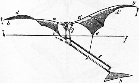
Fig. 40.—Pénaud’s Artificial Flying Bird.
a b c d, a′ b′ c′ d′, Elastic wings, which twist and untwist when made to vibrate. a b, a′ b′, Anterior margins of wings. c d, c′ d′, Posterior margins of wings. c, c′, Inner portions of wings attached to central shaft of model by elastic bands at e. f, India-rubber in a state of torsion, which provides the motive power, by causing the crank situated between the vertical wing supports (g) to rotate; as the crank revolves the wings are made to vibrate by means of two rods which extend between the crank and the roots of the wings. h, Tail of artificial bird.
De Villeneuve and Pénaud constructed their winged models on different types, the former selecting the bat, the latter the bird. De Villeneuve made the wings of his artificial bat conical in shape and comparatively rigid. He controlled the movements of the wings, and made them strike downwards and forwards in imitation of natural wings. His model possessed great power of rising. It elevated itself from the ground with ease, and flew in a horizontal direction for a distance of 24 ft., and at a velocity of 20 m. an hour. Pénaud’s model differed from de Villeneuve’s in being provided with elastic wings, the posterior margins of which in addition to being elastic were free to move round the anterior margins as round axes (see fig. 24). India-rubber springs were made to extend between the inner posterior parts of the wings and the frame, corresponding to the backbone of the bird.
A vertical movement having been communicated by means of india-rubber in a state of torsion to the roots of the wings, the wings themselves, in virtue of their elasticity, and because of the resistance experienced from the air, twisted and untwisted and formed reciprocating screws, precisely analogous to those originally described and figured by Pettigrew in 1867. Pénaud’s arrangement is shown in fig. 40.
If the left wing of Pénaud’s model (a b, c d of fig. 40) be compared with the wing of the bat (fig. 18), or with Pettigrew’s artificial wing (fig. 32), the identity of principle and application is at once apparent.
In Pénaud’s artificial bird the equilibrium is secured by the addition of a tail. The model cannot raise itself from the ground, but on being liberated from the hand it descends 2 ft. or so, when, having acquired initial velocity, it flies horizontally for a distance of 50 or more feet, and rises as it flies from 7 to 9 ft. The following are the measurements of the model in question:—length of wing from tip to tip, 32 in.; weight of wing, tail, frame, india-rubber, &c., 73 grammes (about 2½ ounces).
(J. B. P.)
Flying Machines.—Henson’s flying machine, designed in 1843, was the earliest attempt at aviation on a great scale. Henson was one of the first to combine aerial screws with extensive supporting structures occupying a nearly horizontal position. The accompanying illustration explains the combination (fig. 41).
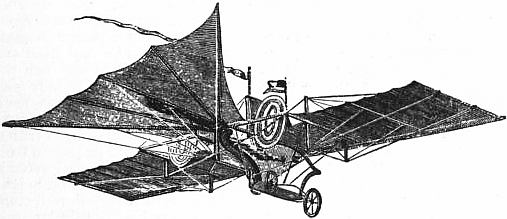
Fig. 41.—Henson’s Aerostat.
“The chief feature of the invention was the very great expanse of its sustaining planes, which were larger in proportion to the weight it had to carry than those of many birds. The machine advanced with its front edge a little raised, the effect of which was to present its under surface to the air over which it passed, the resistance of which, acting upon it like a strong wind on the sails of a windmill, prevented the descent of the machine and its burden. The sustaining of the whole, therefore, depended upon the speed at which it travelled through the air, and the angle at which its under surface impinged on the air in its front.... The machine, fully prepared for flight, was started from the top of an inclined plane, in descending which it attained a velocity necessary to sustain it in its further progress. That velocity would be gradually destroyed by the resistance of the air to the forward flight; it was, therefore, the office of the steam-engine and the vanes it actuated simply to repair the loss of velocity; it was made, therefore, only of the power and weight necessary for that small effect.” The editor of Newton’s Journal of Arts and Sciences speaks of it thus:—“The apparatus consists of a car containing the goods, passengers, engines, fuel, &c., to which a rectangular frame, made of wood or bamboo cane, and covered with canvas or oiled silk, is attached. This frame extends on either side of the car in a similar manner to the outstretched wings of a bird; but with this difference, that the frame is immovable. Behind the wings are two vertical fan wheels, furnished with oblique vanes, which are intended to propel the apparatus through the air. The rainbow-like circular wheels are the propellers, answering to the wheels of a steamboat, and acting upon the air after the manner of a windmill. These wheels receive motions from bands and pulleys from a steam or other engine contained in the car. To an axis at the stern of the car a triangular frame is attached, resembling the tail of a bird, which is also covered with canvas or oiled silk. This may be expanded or contracted at pleasure, and is moved up and down for the purpose of causing the machine to ascend or descend. Beneath the tail is a rudder for directing the course of the machine to the right or to the left; and to facilitate the steering a sail is stretched between two masts which rise from the car. The amount of canvas or oiled silk necessary for buoying up the machine is stated to be equal to one square foot for each half pound of weight.”
F.H. Wenham, thinking to improve upon Henson, invented in 1866 what he designated his aeroplanes.19 These were thin, light, long, narrow structures, arranged above each other in tiers like so many shelves. They were tied together at a slight upward angle, and combined strength and lightness. The idea was to obtain great sustaining area in comparatively small space with comparative ease of control. It was hoped that when the aeroplanes were wedged forward in the air by vertical screws, or by the body to be flown, each aeroplane would rest or float upon a stratum of undisturbed air, and that practically the aeroplanes would give the same support as if spread out horizontally. The accompanying figures illustrate Wenham’s views (figs. 42 and 43).

Fig. 42.—Wenham’s system of Aeroplanes designed to carry a man.
a, a, Thin planks, tapering at each end, and attached to a triangle. b, Similar plank for supporting the aeronaut. c, c, Thin bands of iron with truss planks a, a, and d, d, Vertical rods. Between these are stretched five bands of holland 15 in. broad and 16 ft. long, the total length of the web being 80 ft. This apparatus when caught by a gust of wind, actually lifted the aeronaut.
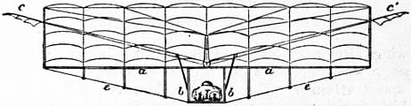
Fig. 43.—A similar system, planned by Wenham.
a, a, Main spar 16 ft. long; b, b, Panels, with base board for aeronaut attached to main spar. e, e, Thin tie-band of steel with struts starting from main spar. This forms a strong light framework for the aeroplanes, consisting of six webs of thin holland 15 in. broad. The aeroplanes are kept in parallel plane by vertical divisions of holland 2 ft. wide. c, c′, Wing propellers driven by the feet.
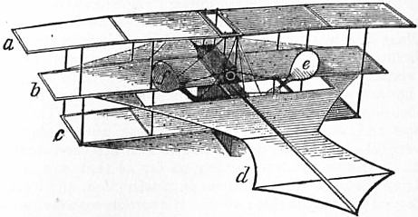
Fig. 44.—Stringfellow’s Flying Machine.
Stringfellow, who was originally associated with Henson, and built a successful flying model in 1847, made a second model in 1868, in which Wenham’s aeroplanes were combined with aerial screws. This model was on view at the exhibition of the Aeronautical Society of Great Britain, held at the Crystal Palace, London, in 1868. It was remarkably compact, elegant and light, and obtained the £100 prize of the exhibition for its engine, which was the lightest and most powerful so far constructed. The illustration below (fig. 44), drawn from a photograph, gives a very good idea of the arrangement—a, b, c representing the superimposed aeroplanes, d the tail, e, f the screw propellers. The superimposed aeroplanes (a, b, c) in this machine contained a sustaining area of 28 sq. ft., in addition to the tail (d). Its engine represented a third of a horse power, and the weight of the whole (engine, boiler, water, fuel, superimposed aeroplanes and propellers) was under 12 ℔ Its sustaining area, if that of the tail (d) be included, was something like 36 sq. ft., i.e. 3 sq. ft. for every pound. The model was forced by its propellers along a wire at a great speed, but so far as an observer could determine, failed to lift itself, notwithstanding its extreme lightness and the comparatively very great power employed. Stringfellow, however, stated that it occasionally left the wire and was sustained by its aeroplanes alone.
The aerial steamer of Thomas Moy (fig. 45), designed in 1874, consisted of a light, powerful, skeleton frame resting on three wheels; a very effective light engine constructed on a new principle, which dispensed with the old-fashioned, cumbrous boiler; two long, narrow, horizontal aeroplanes; and two comparatively very large aerial screws. The idea was to get up the initial velocity by a preliminary run on the ground. This accomplished it was hoped that the weight of the machine would gradually be thrown upon the aeroplanes in the same way that the weight of certain birds—the eagle, e.g.—is thrown upon the wings after a few hops and leaps. Once in the air the aeroplanes, it was believed, would become effective in proportion to the speed attained. The machine, however, did not realize the high expectations formed of it, and like all its predecessors it was doomed to failure.
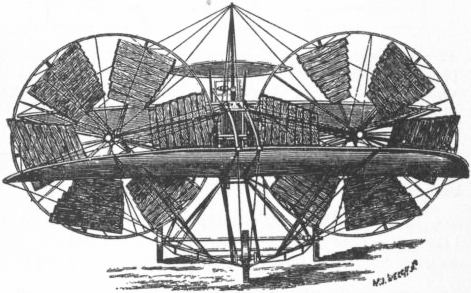
Fig. 45.—Moy’s Aerial Steamer.
Two of the most famous of the next attempts to solve the problem of artificial flight, by means of aeroplanes, were those of Prof. S.P. Langley and Sir Hiram S. Maxim, who began their aerial experiments about the same time (1889-1890). By 1893-1894 both had embodied their views in models and large flying machines.
Langley, who occupied the position of secretary to the Smithsonian Institution, Washington, U.S.A., made many small flying models and one large one. These he designated “aerodromes.” They were all constructed on a common principle, and were provided with extensive flying surfaces in the shape of rigid aeroplanes inclined at an upward angle to the horizon, and more or less fixed on the plan advocated by Henson. The cardinal idea was to force the aeroplanes (slightly elevated at their anterior margins) forwards, kite-fashion, by means of powerful vertical screw propellers driven at high speed—the greater the horizontal speed provided by the propellers, the greater, by implication, the lifting capacity of the aerodrome. The bodies, frames and aeroplanes of the aerodromes were strengthened by vertical and other supports, to which were attached aluminium wires to ensure absolute rigidity so far as that was possible. Langley aimed at great lightness of construction, and in this he succeeded to a remarkable extent. His aeroplanes were variously shaped, and were, as a rule, concavo-convex, the convex surface being directed upwards. He employed a competent staff of highly trained mechanics at the Smithsonian Institution, and great secrecy was observed as to his operations. He flew his smallest models in the great lecture room of the National Museum, and his larger ones on the Potomac river about 40 m. below Washington.
While Langley conducted his preliminary experiments in 1889, he did not construct and test his steam-driven flying models until 1893. These were made largely of steel and aluminium, and one of them in 1896 made the longest flight then recorded for a flying machine, namely, fully half a mile on the Potomac river. The largest aerodrome, intended to carry passengers and to be available for war purposes, was built to the order and at the expense of the American government, which granted a sum of fifty thousand dollars for its construction.
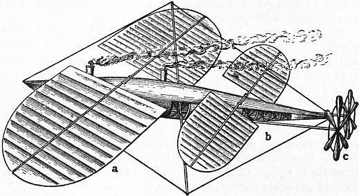
Fig. 46.—Langley’s Flying Machine. a, Large aeroplane; b, Small aeroplane; c, Propelling screws.
Langley’s machine shown in fig. 46 was a working model, not intended to carry passengers. In configuration the body-portion closely resembled a mackerel. The backbone was a light but very rigid tube of aluminium steel, 15 ft. in length, and a little more than 2 in. in diameter. The engines were located in the portion of the framework corresponding to the head of the fish; they weighed 60 oz. and developed one horse-power. There were four boilers made of thin hammered copper and weighing a little more than 7 ℔ each; these occupied the middle portion of the fish. The fuel used was refined gasoline, and the extreme end of the tail of the fish was utilized for a storage tank with a capacity of one quart. There were twin screw propellers, which could be adjusted to different angles in practice, to provide for steering, and made 1700 revolutions a minute. The wings, or aeroplanes, four in number, consisted of light frames of tubular aluminium steel covered with china silk. The pair in front were 42 in. wide and 40 ft. from tip to tip. They could be adjusted at different angles. The machine required to be dropped from a height, or a preliminary forward impetus had to be given to it, before it could be started. Fixity of all the parts was secured by a tubular mast extending upwards and downwards through about the middle of the craft, and from its extremities ran stays of aluminium wire to the tips of the aeroplanes and the end of the tubular backbone. By this trussing arrangement the whole structure was rendered exceedingly stiff.
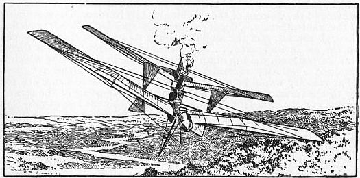
Fig. 47.—Langley’s Aerodrome in flight.
In the larger aerodrome (fig. 47) the aeroplanes were concavo-convex, narrow, greatly elongated and square at their free extremities, the two propellers, which were comparatively very large, being placed amidships, so to speak. At the first trial of this machine, on the 7th of October 1903, just as it left the launching track it was jerked violently down at the front (being caught, as subsequently appeared, by the falling ways), and under the full power of its engine was pulled into the water, carrying with it its engineer. When the aerodrome rose to the surface, it was found that while the front sustaining surfaces had been broken by their impact with the water, yet the rear ones were comparatively uninjured. At the second and last attempt, on the 8th of December 1903, another disaster, again due to the launching ways, occurred as the machine was leaving the track. This time the back part of the machine, in some way still unexplained, was caught by a portion of the launching car, which caused the rear sustaining surface to break, leaving the rear entirely without support and it came down almost vertically into the water. Darkness had come before the engineer, who had been in extreme danger, could aid in the recovery of the aerodrome. The boat and machine had drifted apart, and one of the tugs in its zeal to render assistance had fastened a rope to the frame of the machine in the reverse position from what it should have been attached, and had broken the frame entirely in two. Owing to lack of funds further trials were abandoned (see Annual Report of the Smithsonian Institution, 1904, p. 122).
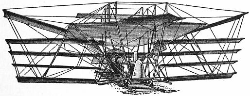
Fig. 48.—Sir H. Maxim’s Flying Machine.
Sir Hiram S. Maxim, like Langley, employed a staff of highly skilled workmen. His machine (fig. 48) consisted of a platform, on which stood a large water-tube boiler, a number of concavo-convex aeroplanes arranged in tiers like shelves, each making a slight upward angle with the horizon, two very large vertical screws placed aft and propelled by steam engines, tanks for the storage of water, naphtha, &c. The boiler was especially noteworthy. The water was contained in about 2000 bent copper tubes, only 3⁄8 in. in external diameter, heated by over 7000 gas jets arranged in rows. The fuel was naphtha or gasoline. Steam could be got up in the short space of half a minute. The steam-generating appliances, which weighed only 1000 ℔ in all, were placed in the front of the machine. The motive power was provided by a pair of two-cylinder, compound engines, poised about 8 ft. from the ground, and about 6 ft. apart. Each of them was independently governed, and furnished together 363 horse-power in actual effect, an amount which, considering that their total weight was only 600 ℔, gave the extraordinary efficiency of over 1 horse-power for every 2 ℔ weight. The high and the low pressure cylinders were 5 and 8 in. in diameter respectively, and the stroke was 12 in. When going at full speed these engines conferred 425 revolutions per minute on the two gigantic propellers that drove the machine along. These were in appearance like two-bladed marine propellers except that they were square instead of rounded at the ends, and were broad and thin. They were built from overlapping strips of American pine, planed smooth and covered with glued canvas. They weighed 135 ℔ each, the length of each blade being close upon 9 ft. and the width at the ends 5½ ft. The pitch was 16 ft. They were carefully stayed by steel wires to their shafts, or the first revolution would have snapped them off short. The material of which the framework was built was thin steel tubing, exceedingly light. All the wires and ties were of the best steel, capable of standing a strain of 100 tons to the square inch. The body of the machine was oblong in shape, with the fore-part cut away like a water-chute boat, and a long counter at the stern over which the propellers revolved. It had canvas stretched all over it. High overhead, like a gigantic awning, was the slightly concavo-convex main aeroplane, tilted towards the front at an imperceptible angle, and stretched taut. Its area was 1400 sq. ft., increased by side wings to 2700 sq. ft. There were also side aeroplanes arranged in tiers, and large aeroplanes in front, which were pivoted and served for vertical steering. The machine was strengthened in every direction by vertical and other supports and securely wired together at all points. It was furnished with four strong flanged wheels and ran along a light broad-gauge (9 ft.) railway track, 1800 ft. long, in the hope that when the speed reached a certain point it would leave the rails, but it was prevented from rising more than an inch or so by four arms, or outriggers, furnished with wheels, which projected from its sides and ran under an inverted wooden upper or safety track outside the railway track proper.
At a trial carried out in 1894 at Bexley, Kent, only the main aeroplane, the fore and aft rudders, and the top and bottom side planes were in position. After everything had been got in readiness, careful observers were stationed along the track, and the machine was connected to a dynamometer. The engines were then started and the pump set so as to deliver over 5000 ℔ of water per hour into the boiler. The gas was then carefully turned on until the pressure amounted to 310 ℔ per sq. in., and the dynamometer showed a thrust of more than 2100 ℔ A small safety-valve placed in the steam pipe had been adjusted so as to blow off slightly at 310 ℔ and with a strong blast at 320 ℔ The signal being given to let go, the machine darted forward at a terrific pace, and the safety-valve ceased to blow. More gas was instantly turned on, and before the machine had advanced 300 ft., the steam had mounted to 320 ℔ per sq. in., and the safety-valve was blowing off a steady blast. When the machine had travelled only a few hundred feet, all four of the small outrigger wheels were fully engaged, which showed that the machine was lifting at least 8000 ℔ The speed rapidly increased until when the machine had run about 900 ft. one of the rear axletrees, which were of 2 in. steel tubing, doubled up and set the rear end of the machine completely free. When the machine had travelled about 1000 ft., the left-hand forward wheel became disengaged from the safety track, and shortly after this the right-hand wheel broke the upper track—3 in. by 9 in. Georgia pine—and a plank became entangled in the framework of the machine. Steam had already been shut off, and the machine coming to rest fell directly to the ground, all four of its wheels sinking deeply into the turf without leaving other marks. Before making this run the wheels which were to engage the upper track were painted, and the paint left by them on the upper track indicated the exact point where the machine lifted. The area of the aeroplanes was very nearly 4000 sq. ft. and the total lifting effect was fully 10,000 ℔ The planes therefore lifted 2.5 ℔ per sq. ft., and 5 ℔ for each pound thrust. Nearly half of the power of the engines was lost in the screw slip. This showed that the diameter of the screws was not great enough; it should have been at least 22 ft.
In 1897 M.C. Ader, who had already tested, with indifferent results, two full-sized flying machines, built a third apparatus with funds furnished by the French government. This reproduced the structure of a bird with almost servile imitation, save that traction was obtained by two screw-propellers. The steam engine weighed about 7 ℔ per horse-power, but the equilibrium of the apparatus was defective.
Largely with the view of studying the problem of maintaining equilibrium, several experimenters, including Otto Lilienthal, Percy Pilcher and Octave Chanute, cultivated gliding flight by means of aeroplanes capable of sustaining a man. They depended mainly on the utilization of natural air currents, trusting for stability and balance to movements in their own bodies, or in portions of their machines which they could control. They threw themselves from natural or artificial elevations, or, facing the wind, they ran or were dragged forwards against it until they got under way and the wind caught hold of their aeroplanes. To Lilienthal in Germany belongs the double credit of demonstrating the superiority of arched over flat surfaces, and of reducing gliding flight to regular practice. He made over 2000 glides safely, using gravity as his motive power, with concave, batlike wings, in some cases with superposed surfaces (fig. 49). It was with a machine of the latter type that he was upset by a sudden gust of wind and killed in 1896. Pilcher in England improved somewhat on Lilienthal’s apparatus, but used the same general method of restoring the balance, when endangered, by shifting the weight of the operator’s body. He too made several hundred glides in safety, but finally was thrown over by a gust of wind and killed in 1899. Chanute in America confined his endeavours to the production of automatic stability, and made the surfaces movable instead of the man. He used several different forms of apparatus, including one with five superposed pairs of wings and a tail (fig. 50) and another with two continuous aeroplanes, one above the other (fig. 51). He made over 1000 glides without accident.
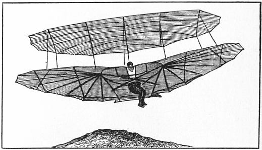
Fig. 49.—Lilienthal’s Gliding Machine.
Similar experiments were meanwhile conducted by Wilbur and Orville Wright of Dayton, Ohio, in whose hands the glider developed into a successful flying machine. These investigators began their work in 1900, and at an early stage introduced two characteristic features—a horizontal rudder in front for steering in the vertical plane, and the flexing or bending of the ends of the main supporting aeroplanes as a means of maintaining the structure in proper balance. Their machines to begin with were merely gliders, the operator lying upon them in a horizontal, position, but in 1903 a petrol motor was added, and a flight lasting 59 seconds was performed. In 1905 they made forty-five flights, in the longest of which they remained in the air for half an hour and covered a distance of 24½ m. The utmost secrecy, however, was maintained concerning their experiments, and in consequence their achievements were regarded at the time with doubt and suspicion, and it was hardly realized that their success would reach the point later achieved.
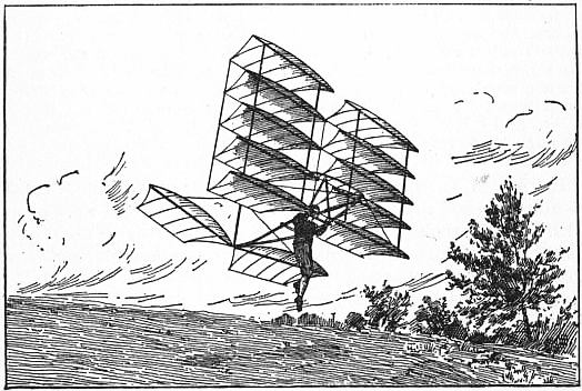
Fig. 50.—Chanute’s Multiple Gliding Machine.
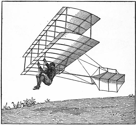
Fig. 51.—Chanute’s Biplane Gliding Machine.
Thanks, however, to the efforts of automobile engineers, great improvements were now being effected in the petrol engine, and, although the certainty and trustworthiness of its action still left something to be desired, it provided the designers of flying machines with what they had long been looking for—a motor very powerful in proportion to its weight. Largely in consequence of this progress, and partly no doubt owing to the stimulus given by the activity of builders of dirigible balloons, the construction of motor-driven aeroplanes began to attract a number of workers, especially in France. In 1906 A. Santos Dumont, after a number of successful experiments with dirigible cigar-shaped gas balloons, completed an aeroplane flying machine. It consisted of the following parts:—(a) A system of aeroplanes arranged like the capital letter T at a certain upward angle to the horizon and bearing a general resemblance to box kites; (b) a pair of very light propellers driven at a high speed; and (c) an exceedingly light and powerful petrol engine. The driver occupied a position in the centre of the arrangement, which is shown in fig. 52. The machine was furnished with two wheels and vertical supports which depended from the anterior parts of the aeroplanes and supported it when it touched the ground on either side. With this apparatus he traversed on the 12th of November 1906 a distance of 220 metres in 21 seconds.
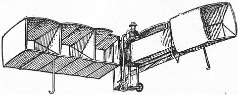
Fig. 52.—Santos Dumont’s Flying Machine.
About a year later Henry Farman made several short flights on a machine of the biplane type, consisting of two main supporting surfaces one above the other, with a box-shaped vertical rudder behind and two small balancing aeroplanes in front. The engine was an eight-cylinder Antoinette petrol motor, developing 49 horse-power at 1100 revolutions a minute, and driving directly a single metal screw propeller. On the 27th of October 1906 he flew a distance of nearly half a mile at Issy-les-Molineaux, and on the 13th of January 1908 he made a circular flight of one kilometre, thereby winning the Deutsch-Archdeacon prize of £2000. In March he remained in the air for 3½ minutes, covering a distance of 1¼ m.; but in the following month a rival, Leon Delagrange, using a machine of the same type and constructed by the same makers, Messrs Voisin, surpassed this performance by flying nearly 2½ m. in 6½ minutes. In July Farman remained in the air for over 20 minutes; on the 6th of September Delagrange increased the time to nearly 30 minutes, and on the 29th of the same month Farman again came in front with a flight lasting 42 minutes and extending over nearly 24½ m.
But the best results were obtained by the Wright brothers—Orville Wright in America and Wilbur Wright in France. On the 9th of September 1908 the former, at Fort Myer, Virginia, made three notable flights; in the first he remained in the air 57½ minutes and in the second 1 hour 3 minutes, while in the third he took with him a passenger and covered nearly 4 m. in 6 minutes. Three days later he made a flight of 45 m. in 1 hour 141⁄3 minutes, but on the 17th he had an accident, explained as being due to one of his propellers coming into contact with a stay, by which his machine was wrecked, he himself seriously injured, and Lieutenant Selfridge, who was with him, killed. Four days afterwards Wilbur Wright at Le Mans in France beat all previous records with a flight lasting 1 hour 31 minutes 254⁄5 seconds, in which he covered about 56 m.; and subsequently, on the 11th of October, he made a flight of 1 hour 9 minutes accompanied by a passenger. On the 31st of December he succeeded in remaining in the air for 2 hours 20 minutes 23 seconds.
Wilbur Wright’s machine (fig. 53), that used by his brother being essentially the same, consisted of two slightly arched supporting surfaces, each 12½ metres long, arranged parallel one above the other at a distance of 14⁄5 metres apart. As they were each about 2 metres wide their total area was about 50 sq. metres. About 3 metres in front of them was arranged a pair of smaller horizontal aeroplanes, shaped like a long narrow ellipse, which formed the rudder that effected changes of elevation, the driver being able by means of a lever to incline them up or down according as he desired to ascend or descend. The rudder for lateral steering was placed about 2½ metres behind the main surfaces and was formed of two vertical pivoted aeroplanes. The lever by which they were turned was connected with the device by which the ends of the main aeroplanes could be flexed simultaneously though in opposite directions; i.e. if the ends of the aeroplanes on one side were bent downwards, those on the other were bent upwards. By the aid of this arrangement the natural cant of the machine when making a turn could be checked, if it became excessive. The four-cylinder petrol engine was placed on the lower aeroplane a little to the right of the central line, being counterbalanced by the driver (and passenger if one was carried), who sat a little to the left of the same line. Making about 1200 revolutions a minute, it developed about 24 horse-power, and was connected by chain gearing to two wooden propellers, 2½ metres in diameter and 3½ metres apart, the speed of which was about 450 revolutions a minute. The whole machine, with aeronaut, weighed about 1100 ℔, the weight of the motor being reputed to be 200 ℔
Plate I.
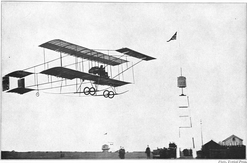
Fig. 1.—PAULHAN FLYING ON FARMAN BIPLANE.
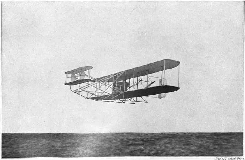
Fig. 2.—WRIGHT BIPLANE.
Plate II.
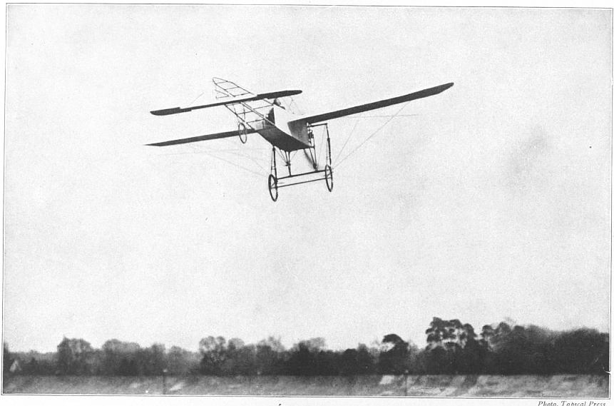
Fig. 3.—BLERIOT MONOPLANE.
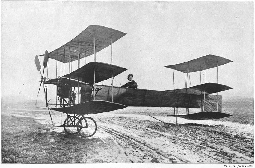
Fig. 4.—A.V. ROE’S TRIPLANE.
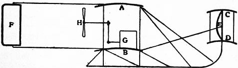
Fig. 53.—Wright Flying Machine; diagrammatic sketch.
A, B, Main supporting surfaces. C, D, Aeroplanes of horizontal rudder with fixed semilunar fin E. F, Vertical rudder. G, Motor. H, Screws.
A feature of the year 1909 was the success obtained with monoplanes having only a single supporting surface, and it was on a machine of this type that the Frenchman Blériot on July 25th flew across the English Channel from Calais to Dover in 31 minutes. Hubert Latham all but performed the same feat on an Antoinette monoplane. The year saw considerable increases in the periods for which aviators were able to remain in the air, and Roger Sommer’s flight of nearly 2½ hours on August 7th was surpassed by Henry Farman on November 3rd, when he covered a distance estimated at 137¼ m. in 4 hr. 17 min. 53 sec. In both these cases biplanes were employed. Successful aviation meetings were held, among other places, at Reims, Juvisy, Doncaster and Blackpool; and at Blackpool a daring flight was made in a wind of 40 m. an hour by Latham. This aviator also proved the possibility of flying at considerable altitudes by attaining on December 1st a height of over 1500 ft., but this record was far surpassed in the following January by L. Paulhan, who on a biplane rose to a height of 1383 yds. at Los Angeles. In the course of the year three aviators were killed—Lefèvbre and Ferber in September and Fernandez in December; and four men perished in September by the destruction of the French airship “République,” the gas-bag of which was ripped open by a broken propeller. In January 1910 Delagrange was killed by the fracture of one of the wings of a monoplane on which he was flying. On April 27th-28th, 1910, Paulhan successfully flew from London to Manchester, with only one stop, within 24 hours, for the Daily Mail’s £10,000 prize.
The progress made by all these experiments at aviation had naturally created widespread interest, both as a matter of sport and also as indicating a new departure in the possibilities of machines of war. And in 1909 the British government appointed a scientific committee, with Lord Rayleigh as chairman, as a consultative body for furthering the development of the science in England.
The table below gives some details, approximately correct, of the principal experiments made with flying machines up to 1908.
Year. Experimenter. Tip to Tip. Surface. Weight. Pounds per sq. ft. Speed per hour. Maximum Flight. Motor. Horse- power. Pounds sustained per h.p.
Ft. Sq. ft. ℔ Mls. Ft.
1879 Tatin 6.2 7.5 3.85 0.51 18 100? Compressed air 0.03 110?
1885 1889 Hargrave (No. 16) 5.5 26.0 5.00 0.19 10 343 ” 0.06 79
1893 Phillips 22.0 136.0 402.00 3.00 28 500? Steam 5.6 72?
1894 Maxim* 50.0 4000.0 8000.00 2.5 36 300? ” 363.00 28
1896 Langley 12.0 70.0 30.00 0.43 24 4,000 ” 1.00 30
1897 Tatin and Richet 21.0 86.0 72.00 0.83 40 460 ” 1.33 55
1897 Ader* 49.0 270.0 1100.00 4.00 50? 100? ” 40.00 27
1895 Lilienthal* 23.0 151.0 220.00 1.46 23 1,200 Gravity 2.00 110
1896 Pilcher* 23.0 170.0 200.00 1.17 25 900 ” 2.00 100
1896 Chanute* 16.0 135.0 178.00 1.31 22 360 ” 2.00 89
1906 S. Dumont* 39 560 550 0.98 22.26 2,900 Petrol 50 23
1908 W. Wright* 41 650 1100 1.7 37 295,000 Petrol 24 46
* The apparatus marked thus * carried a man or men.
References.—Some of the books mentioned under Aeronautics contain details of flying machines; see H.W.L. Moedebeck, A Pocketbook of Aeronautics, trans. by W. Mansergh Varley (London, 1907); Sir Hiram S. Maxim, Artificial and Natural Flight (London, 1908); F.W. Lanchester, Aerodynamics and Aerodonetics (London, 1907 and 1908); C.C. Turner, Aerial Navigation of To-day (London, 1909); also two papers on “Aerial Navigation” read by Colonel G.O. Fullerton before the Royal United Service Institution in 1892 and 1906; papers read by Major B.F.S. Baden-Powell and E.S. Bruce before the Society of Arts, London, in April 1907 and December 1908 respectively; Cantor Lectures by F.W. Lanchester (Society of Arts, 1909); and the Proceedings of the Aeronautical Society (founded 1865), &c.
1 According to Dr Crisp, the swallow, martin, snipe and many birds of passage have no air in their bones.—Proc. Zool. Soc. Lond. part xxv., 1857, p. 13.
2 By the term aeroplane is meant a thin, light, expanded structure inclined at a slight upward angle to the horizon intended to float or rest upon the air, and calculated to afford a certain amount of support to any body attached to it.
3 “On the Various Modes of Flight in relation to Aeronautics,” by J. Bell Pettigrew, Proc. Roy. Inst., 1867; “On the Mechanical Appliances by which Flight is attained in the Animal Kingdom,” by the same author, Trans. Linn. Soc., 1867.
4 Revue des cours scientifiques de la France et de l’Étranger, 1869.
5 The sphygmograph, as its name indicates, is a recording instrument. It consists of a smoked cylinder revolving by means of clock-work at a known speed, and a style or pen which inscribes its surface by scratching or brushing away the lampblack. The movements to be registered are transferred to the style or pen by one or more levers, and the pen in turn transfers them to the cylinder, where they appear as legible tracings. In registering the movements of the wings the tips and margins of the pinions were, by an ingenious modification, employed as the styles or pens. By this arrangement the different parts of the wings were made actually to record their own movements. As will be seen from this account, the figure-of-8 or wave theory of stationary and progressive flight has been made the subject of a rigorous experimentum crucis.
6 This continuity of the down into the up stroke and the converse is greatly facilitated by the elastic ligaments at the root and in the substance of the wing. These assist in elevating, and, when necessary, in flexing and elevating it. They counteract in some measure what may be regarded as the dead weight of the wing, and are especially useful in giving it continuous play.
7 “The importance of the twisted configuration or screw-like form cannot be over-estimated. That this shape is intimately associated with flight is apparent from the fact that the rowing feathers of the wing of the bird are every one of them distinctly spiral in their nature; in fact, one entire rowing feather is equivalent—morphologically and physiologically—to one entire insect wing. In the wing of the martin, where the bones of the pinion are short, and in some respects rudimentary, the primary and secondary feathers are greatly developed, and banked up in such a manner that the wing as a whole presents the same curves as those displayed by the insect’s wing, or by the wing of the eagle, where the bones, muscles and feathers have attained a maximum development. The conformation of the wing is such that it presents a waved appearance in every direction—the waves running longitudinally, transversely and obliquely. The greater portion of the wing may consequently be removed without essentially altering either its form or its functions. This is proved by making sections in various directions, and by finding that in some instances as much as two-thirds of the wing may be lopped off without materially impairing the power of flight.”—Trans. Roy. Soc. Edin. vol. xxvi. pp. 325, 326.
8 “On the Various Modes of Flight in relation to Aeronautics,” Proc. Roy. Inst., 1867; “On the Mechanical Appliances by which Flight is attained in the Animal Kingdom,” Trans. Linn. Soc., 1867, 26.
9 “On the Physiology of Wings; being an analysis of the movements by which flight is produced in the Insect, Bat and Bird,” Trans. Roy. Soc. Edin. vol. 26.
10 The other forces which assist in elevating the wings are—(a) the elevator muscles of the wings, (b) the elastic properties of the wings, and (c) the reaction of the compressed air on the under surfaces of the wings.
11 The wings of the albatross, when fully extended, measure across the back some 14 ft. They are exceedingly narrow, being sometimes under a foot in width.
12 On the Flight of Birds, of Bats and of Insects, in reference to the subject of Aerial Locomotion, by L. de Lucy (Paris).
13 E.J. Marey, Revue des cours scientifiques de la France et de l’étranger (1869).
14 “The Aero-bi-plane, or First Steps to Flight,” Ninth Annual Report of the Aeronautical Society of Great Britain, 1874.
15 “Resistance to Falling Planes on a Path of Translation,” Ninth Annual Report of the Aeronautical Society of Great Britain, 1874.
16 The Aeronaut for January 1872 and February 1875.
17 Cayley’s screws, as explained, were made of feathers, and consequently elastic. As, however, no allusion is made in his writings to the superior advantages possessed by elastic over rigid screws, it is to be presumed that feathers were employed simply for convenience and lightness. Pettigrew, there is reason to believe, was the first to advocate the employment of elastic screws for aerial purposes.
18 Stringfellow constructed a second model, which is described and figured further on (fig. 44).
19 “On Aerial Locomotion,” Aeronautical Society’s Report for 1867.
FLINCK, GOVERT (1615-1660), Dutch painter, born at Cleves in 1615, was apprenticed by his father to a silk mercer, but having secretly acquired a passion for drawing, was sent to Leuwarden, where he boarded in the house of Lambert Jacobszon, a Mennonite, better known as an itinerant preacher than as a painter. Here Flinck was joined by Jacob Backer, and the companionship of a youth determined like himself to be an artist only confirmed his passion for painting. Amongst the neighbours of Jacobszon at Leuwarden were the sons and relations of Rombert Ulenburg, whose daughter Saske married Rembrandt in 1634. Other members of the same family lived at Amsterdam, cultivating the arts either professionally or as amateurs. The pupils of Lambert probably gained some knowledge of Rembrandt by intercourse with the Ulenburgs. Certainly J. von Sandrart, who visited Holland in 1637, found Flinck acknowledged as one of Rembrandt’s best pupils, and living habitually in the house of the dealer Hendrik Ulenburg at Amsterdam. For many years Flinck laboured on the lines of Rembrandt, following that master’s style in all the works which he executed between 1636 and 1648; then he fell into peculiar mannerisms by imitating the swelling forms and grand action of Rubens’s creations. Finally he sailed with unfortunate complacency into the Dead Sea of official and diplomatic painting. Flinck’s relations with Cleves became in time very important. He was introduced to the court of the Great Elector, Frederick William of Brandenburg, who married in 1646 Louisa of Orange. He obtained the patronage of John Maurice of Orange, who was made stadtholder of Cleves in 1649. In 1652 a citizen of Amsterdam, Flinck married in 1656 an heiress, daughter of Ver Hoeven, a director of the Dutch East India Company. He was already well known even then in the patrician circles over which the burgomasters De Graef and the Echevin Six presided; he was on terms of intimacy with the poet Vondel and the treasurer Uitenbogaard. In his house, adorned with antique casts, costumes, and a noble collection of prints, he often received the stadtholder John Maurice, whose portrait is still preserved in the work of the learned Barleius.
The earliest of Flinck’s authentic pieces is a likeness of a lady, dated 1636, in the gallery of Brunswick. His first subject picture is the “Blessing of Jacob,” in the Amsterdam museum (1638). Both are thoroughly Rembrandtesque in effect as well as in vigour of touch and warmth of flesh tints. The four “civic guards” of 1642, and “the twelve musketeers” with their president in an arm-chair (1648), in the town-hall at Amsterdam, are fine specimens of composed portrait groups. But the best of Flinck’s productions in this style is the peace of Münster in the museum of Amsterdam, a canvas with 19 life-size figures full of animation in the faces, “radiant with Rembrandtesque colour,” and admirably distributed. Flinck here painted his own likeness to the left in a doorway. The mannered period of Flinck is amply illustrated in the “Marcus Curius eating Turnips before the Samnite Envoys,” and “Solomon receiving Wisdom,” in the palace on the Dam at Amsterdam. Here it is that Flinck shows most defects, being faulty in arrangement, gaudy in tint, flat and shallow in execution, and partial to whitened flesh that looks as if it had been smeared with violet powder and rouge. The chronology of Flinck’s works, so far as they are seen in public galleries, comprises, in addition to the foregoing, the “Grey Beard” of 1639 at Dresden, the “Girl” of 1641 at the Louvre, a portrait group of a male and female (1646) at Rotterdam, a lady (1651) at Berlin. In November 1659 the burgomaster of Amsterdam contracted with Flinck for 12 canvases to represent four heroic figures of David and Samson and Marcus Curius and Horatius Cocles, and scenes from the wars of the Batavians and Romans. Flinck was unable to finish more than the sketches. In the same year he received a flattering acknowledgment from the town council of Cleves on the completion of a picture of Solomon which was a counterpart of the composition at Amsterdam. This and other pictures and portraits, such as the likenesses of Frederick William of Brandenburg and John Maurice of Nassau, and the allegory of “Louisa of Orange attended by Victory and Fame” and other figures at the cradle of the first-born son of the elector, have disappeared. Of several pictures which were painted for the Great Elector, none are preserved except the “Expulsion of Hagar” in the Berlin museum. Flinck died at Amsterdam on the 22nd of February 1660.
FLINDERS, MATTHEW (1774-1814), English navigator, explorer, and man of science, was born at Donington, near Boston, in Lincolnshire, on the 16th of March 1774. Matthew was at first designed to follow his father’s profession of surgeon, but his enthusiasm in favour of a life of adventure impelled him to enter the royal navy, which he did on the 23rd of October 1789. After a voyage to the Friendly Islands and West Indies, and after serving in the “Bellerophon” during Lord Howe’s “glorious first of June” (1794) off Ushant, Flinders went out in 1795 as midshipman in the “Reliance” to New South Wales. For the next few years he devoted himself to the task of accurately laying down the outline and bearings of the Australian coast, and he did his work so thoroughly that he left comparatively little for his successors to do. With his friend George Bass, the surgeon of the “Reliance,” in the year of his arrival he explored George’s river; and, after a voyage to Norfolk Island, again in March 1796 the two friends in the same boat, the “Tom Thumb,” only 8 ft. long, and with only a boy to help them, explored a stretch of coast to the south of Port Jackson. After a voyage to the Cape of Good Hope, when he was promoted to a lieutenancy, Flinders was engaged during February 1798 in a survey of the Furneaux Islands, lying to the north of Tasmania. His delight was great when, in September of the same year, he was commissioned along with Bass, who had already explored the sea between Tasmania and the south coast to some extent and inferred that it was a strait, to proceed in the sloop “Norfolk” (25 tons) to prove conclusively that Van Diemen’s Land was an island by circumnavigating it. In the same sloop, in the summer of next year, Flinders made an exploration to the north of Port Jackson, the object being mainly to survey Glasshouse Bay (Moreton Bay) and Hervey’s Bay. Returning to England he was appointed to the command of an expedition for the thorough exploration of the coasts of Terra Australis, as the southern continent was still called, though Flinders is said to have been the first to suggest for it the name Australia. On the 18th of July 1801 the sloop “Investigator” (334 tons), in which the expedition sailed, left Spithead, Flinders being furnished with instructions and with a passport from the French government to all their officials in the Eastern seas. Among the scientific staff was Robert Brown, one of the most eminent English botanists; and among the midshipmen was Flinders’s relative, John Franklin, of Arctic fame. Cape Leeuwin, on the south-west coast of Australia, was reached on November 6, and King George’s sound on the 9th of December. Flinders sailed round the Great Bight, examining the islands and indentations on the east side, noting the nature of the country, the people, products, &c., and paying special attention to the subject of the variation of the compass. Spenser and St Vincent Gulfs were discovered and explored. On the 8th of April 1802, shortly after leaving Kangaroo Islands, at the mouth of St Vincent Gulf, Flinders fell in with the French exploring ship, “Le Géographe,” under Captain Nicolas Baudin, in the bay now known as Encounter Bay. In the narrative of the French expedition published in 1807 (when Flinders was a prisoner in the Mauritius) by M. Peron, the naturalist to the expedition, much of the land west of the point of meeting was claimed as having been discovered by Baudin, and French names were extensively substituted for the English ones given by Flinders. It was only in 1814, when Flinders published his own narrative, that the real state of the case was fully exposed. Flinders continued his examination of the coast along Bass’s Strait, carefully surveying Port Phillip. Port Jackson was reached on the 9th of May 1802.
After staying at Port Jackson for about a couple of months, Flinders set out again on the 22nd of July to complete his circumnavigation of Australia. The Great Barrier Reef was examined with the greatest care in several places. The north-east entrance of the Gulf of Carpentaria was reached early in November; and the next three months were spent in an examination of the shores of the gulf, and of the islands that skirt them. An inspection of the “Investigator” showed that she was in so leaky a condition that only with the greatest precaution could the voyage be completed in her. Flinders completed the survey of the Gulf of Carpentaria, and after touching at the island of Timor, the “Investigator” sailed round the west and south of Australia, and Port Jackson was reached on the 9th of June 1803. Much suffering was endured by nearly all the members of the expedition: a considerable proportion of the men succumbed to disease, and their leader was so reduced by scurvy that his health was greatly impaired.
Flinders determined to proceed home in H.M.S. “Porpoise” as a passenger, submit the results of his work to the Admiralty, and obtain, if possible, another vessel to complete his exploration of the Australian coast. The “Porpoise” left Port Jackson on the 10th of August, accompanied by the H.E.I.C.’s ship “Bridgewater” (750 tons) and the “Cato” (450 tons) of London. On the night of the 17th the “Porpoise” and “Cato” suddenly struck on a coral reef and were rapidly reduced to wrecks. The officers and men encamped on a small sandbank near, 3 or 4 ft. above high-water, a considerable quantity of provisions, with many of the papers and charts, having been saved from the wrecks. The reef was in about 22° 11′ S. and 155° E., and about 800 m. from Port Jackson. Flinders returned to Port Jackson in a six-oared cutter in order to obtain a vessel to rescue the party. The reef was again reached on the 8th of October, and all the officers and men having been satisfactorily disposed of, Flinders on the 11th left for Jones Strait in an unsound schooner of 29 tons, the “Cumberland,” with ten companions, and a valuable collection of papers, charts, geological specimens, &c. On the 15th of December he put in at Mauritius, when he discovered that France and England were at war. The passport he possessed from the French government was for the “Investigator”; still, though he was now on board another ship, his mission was essentially the same, and the work he was on was simply a continuation of that commenced in the unfortunate vessel. Nevertheless, on her arrival at Port Louis the “Cumberland” was seized by order of the governor-general de Caen. Flinders’s papers were taken possession of, and he found himself virtually a prisoner. We need not dwell on the sad details of this unjustifiable captivity, which lasted to June 1810. But there can be no doubt that the hardships and inactivity Flinders was compelled to endure for upwards of six years told seriously on his health, and brought his life to a premature end. He reached England in October 1810, after an absence of upwards of nine years. The official red-tapeism of the day barred all promotion to the unfortunate explorer, who set himself to prepare an account of his explorations, though unfortunately an important part of his record had been retained by de Caen. The results of his labours were published in two large quarto volumes, entitled A Voyage to Terra Australis, with a folio volume of maps. The very day (July 19, 1814) on which his work was published Flinders died, at the early age of forty. The great work is a model of its kind, containing as it does not only a narrative of his own and of previous voyages, but masterly statements of the scientific results, especially with regard to magnetism, meteorology, hydrography and navigation. Flinders paid great attention to the errors of the compass, especially to those caused by the presence of iron in ships. He is understood to have been the first to discover the source of such errors (which had scarcely been noticed before), and after investigating the laws of the variations, he suggested counter-attractions, an invention for which Professor Barlow got much credit many years afterwards. Numerous experiments on ships’ magnetism were conducted at Portsmouth by Flinders, by order of the admiralty, in 1812. Besides the Voyage, Flinders wrote Observations on the Coast of Van Diemen’s Land, Bass’s Strait, &c., and two papers in the Phil. Trans.—one on the “Magnetic Needle” (1805), and the other, “Observations on the Marine Barometer” (1806).
(J. S. K.)
FLINSBERG, a village and watering-place of Germany, in the Prussian province of Silesia, on the Queis, at the foot of the Iserkamm, 1450 ft. above the sea, 5 m. W. of Friedeberg, the terminus station of the railway from Greiffenberg. Pop. (1900) 1957. It contains an Evangelical and a Roman Catholic church, and has some manufactures of wooden wares. Flinsberg is celebrated for its chalybeate waters, specific in cases of feminine disorders, and used both for bathing and drinking. It is also a climatic health resort of some reputation, and the visitors number about 8500 annually.
See Adam, Bad Flinsberg als klimatischer Kurort (Görlitz, 1891).
FLINT, AUSTIN (1812-1886), American physician, was born at Petersham, Massachusetts, on the 20th of October 1812, and graduated at the medical department of Harvard University in 1833. From 1847 to 1852 he was professor of the theory and practice of medicine in Buffalo Medical College, of which he was one of the founders, and from 1852 to 1856 he filled the same chair in the university of Louisville. From 1861 to 1886 he was professor of the principles and practice of medicine and clinical medicine in Bellevue Hospital Medical College, New York. He wrote many text-books on medical subjects, among these being Diseases of the Heart (1859-1870); Principles and Practice of Medicine (1866); Clinical Medicine (1879); and Physical Exploration of the Lungs by means of Auscultation and Percussion (1882). He died in New York on the 13th of March 1886.
His son, Austin Flint, junr., who was born at Northampton, Massachusetts, on the 28th of March 1836, after studying at Harvard and at the university of Louisville, graduated at the Jefferson Medical College, Philadelphia, in 1857. He then became professor of physiology at the university of Buffalo (1858) and subsequently at other centres, his last connexion being with the Cornell University Medical College (1898-1906). He was better known as a teacher and writer on physiology than as a practitioner, and his Text-book of Human Physiology (1876) was for many years a standard book in American medical colleges. He also published an extensive Physiology of Man (5 vols., 1866-1874), Chemical Examination of the Urine in Disease (1870), Effects of Severe and Protracted Muscular Exercise (1871), Source of Muscular Power (1878), and Handbook of Physiology (1905). In 1896 he became a consulting physician to the New York State Hospital for the Insane.
FLINT, ROBERT (1838- ), Scottish divine and philosopher, was born near Dumfries and educated at the university of Glasgow. After a few years of pastoral service, first in Aberdeen and then at Kilconquhar, Fife, he was appointed professor of moral philosophy and political economy at St Andrews in 1864. From 1876 to 1903 he was professor of divinity at Edinburgh. He contributed a number of articles to the 9th edition of the Encyclopaedia Britannica. His chief works are Christ’s Kingdom upon Earth (Sermons, 1865); Philosophy of History in Europe (1874; partly rewritten with reference to France and Switzerland, 1894); Theism and Anti-theistic Theories (2 vols., being the Baird Lectures for 1876-1877; often reprinted); Socialism (1894); Sermons and Addresses (1899); Agnosticism (1903).
FLINT, TIMOTHY (1780-1840), American clergyman and writer, was born in Reading, Massachusetts, on the 11th of July 1780. He graduated at Harvard in 1800, and in 1802 settled as a Congregational minister in Lunenburg, Mass., where he pursued scientific studies with interest; and his labours in his chemical laboratory seemed so strange to the people of that retired region, that some persons supposed and asserted that he was engaged in counterfeiting. This, together with political differences, led to disagreeable complications, which resulted in his resigning his charge (1814) and becoming a missionary (1815) in the valley of the Mississippi. He was also for a short period a teacher and a farmer. His observations on the manners and character of the settlers of the Ohio and Mississippi valleys were recorded in a picturesque work called Recollections of the Last Ten Years passed in the Valley of the Mississippi (1826; reprinted in England and translated into French), the first account of the western states which brought to light the real life and character of the people. The success which this work met with, together with the failing health of the writer, led him to relinquish his more active labours for literary pursuits, and, besides editing the Western Review in Cincinnati from 1825 to 1828 and Knickerbocker’s Magazine (New York) in 1833, he published a number of books, including Francis Berrian, or the Mexican Patriot (1826), his best novel; A Condensed Geography and History of the Western States, or the Mississippi Valley (2 vols., 1828); Arthur Clenning (1828), a novel; and Indian Wars in the West (1833). His style is vivid, plain and forcible, and his matter interesting; and his works on the western states are of great value. He died in Salem, Mass., on the 16th of August 1840.
FLINT, a city and the county-seat of Genesee county, Michigan, U.S.A., on Flint river, 68 m. (by rail) N.W. of Detroit. Pop. (1890) 9803; (1900) 13,103, of whom 2165 were foreign-born; (1910, census) 38,550. It is served by the Grand Trunk and the Père Marquette railways, and by an electric line, the Detroit United railway, connecting with Detroit. The city has a fine court-house (1904), a federal building (1908), a city hall (1908) and a public library. The Michigan school for the deaf, established in 1854, and the Oak Grove hospital (private) for the treatment of mental and nervous diseases, are here. Flint has important manufacturing interests, its chief manufactures being automobiles, wagons, carriages—Flint is called “the vehicle city,”—flour, woollen goods, iron goods, cigars, beer, and bricks and tiles; and its grain trade is of considerable importance. In 1904 the total value of the city’s factory product was $6,177,170, an increase of 31.1% over that of 1900. The settlement of the place, then called the Grand Traverse of the Flint, began in 1820, but Flint’s growth was very slow until 1831, when it was platted as a village; it was chartered as a city in 1855.
FLINT, or Flintshire (sîr Gallestr), a county of North Wales, the smallest in the country, bounded N. by the Irish Sea and the Dee estuary, N.E. by the Dee, E. by Cheshire, and S.W. by Denbighshire. Area, 257 sq. m. Included in Flint is the detached hundred of Maelor, lying 8 m. S.E. of the main part of the county, and shut in by Cheshire on the N. and N.E., by Shropshire on the S., and by Denbighshire on the W. and N.W. The Clwyd valley is common to Flint and Denbigh. Those of the Alyn and Wepre (from Ewloe Castle to the Dee) are fine. The Dee, entering the county near Overton, divides Maelor from Denbigh on the W., passes Chester and bounds most of the county on the N. The Clwyd enters Flint near Bodfary, and joining the Elwy near Rhuddlan, reaches the Irish Sea near Rhyl. The Alyn enters the county under Moel Fammau, passes Cilcen and Mold (y Wyddgrug), runs underground near Hesb-Alyn (Alyn’s drying-up), bends south to Caergwrle, re-enters Denbighshire and joins the Dee. Llyn Helyg (willow-pool), near Whitford, is the chief lake.
Both for their influence upon the physical features and for their economic value the carboniferous rocks of Flintshire are the most important. From Prestatyn on the coast a band of carboniferous limestone passes close by Holywell and through Caerwen; it forms the Halkin Mountain east of Halkin, whence it continues past Mold to beyond the county boundary. The upper portion of this series is cherty in the north—the chert is quarried for use in the potteries of Staffordshire—but traced southward it passes into sandstones and grits; above these beds come the Holywell shales, possibly the equivalent of the Pendleside series of Lancashire and Derbyshire, while upon them lies the Gwespyr sandstone, which has been thought to correspond to the Gannister coal measures of Lancashire, but may be a representative of the Millstone Grit. Farther to the east, the coal measures, with valuable coals, some oil shale, and with fireclays and marls which are used for brick and tile-making, extend from Talacre through Flint, Northop, Hawarden and Broughton to Hope. The carboniferous rocks appear again through the intervention of a fault, in the neighbourhood of St Asaph. Silurian strata, mostly of Wenlock age, lie below the carboniferous limestone on the western border of the county. Triassic red beds of the Bunter fill the Clwyd valley and appear again on the coal measures S.E. of Chester. Lead and zinc ores have been worked in the lower carboniferous rocks in the north of the county, and caves in the same formation, at Caer Gwyn and Ffynnon Beuno, have yielded the remains of Pleistocene mammals along with palaeolithic implements. Much glacial drift obscures the older rocks on the east and north and in the vale of Clwyd. Short stretches of blown sand occur on the coast near Rhyl and Talacre.
The London & North-Western railway follows the coast-line. Other railways which cross the county are the Great Western, and the Wrexham, Mold & Connah’s Quay, acquired by the Great Central company. For pasture the vale of Clwyd is well known. Oats, turnips and swedes are the chief crops. Stock and dairy farming prospers, native cattle being crossed with Herefords and Downs, native sheep with Leicesters and Southdowns, while in the thick mining population a ready market is found for meat, cheese, butter, &c. The population (81,700 in 1901) nearly doubled in the 19th century, and Flintshire to-day is one of the most densely populated counties in North Wales. The area of the ancient county is 164,744 acres, and that of the administrative county 163,025 acres. The collieries begin at Llanasa, run through Whitford, Holywell, Flint, Halkin (Halcyn), Northop, Buckley, Mold and Hawarden (Penarlâg). At Halkin, Mold, Holywell, Prestatyn and Talacre lead is raised, and is sometimes sent to Bagillt, Flint or Chester to be smelted. Zinc, formerly only worked at Dyserth, has increased in output, and copper mines also exist, as at Talargoch, together with smelting works, oil, vitriol, potash and alkali manufactories. Potteries around Buckley send their produce chiefly to Connah’s Quay, whence a railway crosses the Dee to the Birkenhead (Cheshire) district. Iron seams are now thin, but limestone quarries yield building stone, lime for burning and small stone for chemical works. Fisheries are unproductive and textile manufactures small.
The county returns one member to parliament. The parliamentary borough district (returning one member), consists of Caergwrle, Caerwys, Flint, Holywell, Mold, Overton, St Asaph and Rhuddlan. In addition, there is a small part of the Chester parliamentary borough. There is one municipal borough, Flint (pop. 4625). The other urban districts are: Buckley (5780), Connah’s Quay (3369), Holywell (2652), Mold (4263), Prestatyn (1261) and Rhyl (8473). Flint is in the North Wales and Chester circuit, assizes being held at Mold. The Flint borough has a separate commission of the peace, but no separate court of quarter sessions. The ancient county, which is in the dioceses of Chester, Lichfield and St Asaph, contains forty-six entire ecclesiastical parishes and districts, with parts of eleven others.
Among sites of antiquarian or historical interest, besides the fragmentary ruin of Flint Castle, the following may be mentioned:—Caerwys, near Flint, still shows traces of Roman occupation. Bodfary (Bodfari) was traditionally occupied by the Romans. Moel y gaer (bald hill of the fortress), near Northop, is a remarkably perfect old British post. Maes y Garmon (perhaps for Meusydd Garmon, as y, the article, has no significance before a proper name, and so to be translated, battlefields of Germanus). A mile from Mold is the reputed scene of une victoire sans larmes, gagnée non par les armes, mais par la foi (E.H. Vollet). The Britons, says the legend, were threatened by the Picts and Saxons, at whose approach the Alleluia of that Easter (A.D. 430) was sung. Panic duly seized the invaders, but the victor, St Germanus, confessor and bishop of Auxerre (A.D. 380-448), had to return to the charge in 446. He has, under the name Garmon, a great titular share in British topography. At Bangor Iscoed, “the great high choir in Maelor,” was the monastery, destroyed with over 2000 monks, by Æthelfred of Northumberland in 607, as (by a curious coincidence) its namesake Bangor in Ireland was sacked by the Danes in the 9th century. Bede says (ii. 2) that Bangor monastery was in seven sections, with three hundred (working) monks. The supposed lines of direction of Watt’s and Offa’s dykes were: Basingwerk, Halkin, Hope, Alyn valley, Oswestry (Croes Oswallt, “Oswald’s cross”), for Watt’s, and Prestatyn, Mold, Minera, across the Severn (Hafren, or Sabrina) for Offa’s. Owain Gwynedd (Gwynedd or Venedocia, is North Wales) defeated Henry II. at Coed Ewloe (where is a tower) and at Coleshill (Cynsyllt). Near Pant Asa (pant is a bottom) is the medieval Maen Achwynfan (achwyn, to complain, maen, stone), and tumuli, menhirs (meini hirion) and inscribed stones are frequent throughout the county. There is a 14th-century cross in Newmarket churchyard. Caergwrle Castle seems early Roman, or even British; but most of the castles in the county date from the early Edwards.
See H. Taylor, Flint (London, 1883).
FLINT, a municipal borough and the county town of the above; a seaport and contributory parliamentary borough, on the south of the Dee estuary, 192 m. from London by the London & North-Western railway. Pop. (1901) 4265. The seat of great alkali manufactures, it imports chiefly sulphur and other chemicals, exporting coal, soda, potash, copper, &c. The county gaol here, as at Haverfordwest, occupied an angle of the castle, was removed to Mold, and is now Chester Castle (jointly with Cheshire.)
Flint Castle was built on a lonely rock by the riverside by Edward I. Here met Edward II. and Piers Gaveston. Edward III. bestowed its constableship upon the earls of Chester, and here Richard II. surrendered to Bolingbroke. It was twice taken, after siege, by the parliamentarians, and finally dismantled in 1647. There remain a square court (with angle towers), round tower and drawbridge, all three entrusted to a constable, appointed by the crown under the Municipal Corporations Reforms Act. Made a borough by Edward I., Flint was chartered by Edward III., and by Edward the Black Prince, as earl of Chester.
FLINT (a word common in Teutonic and Scandinavian languages, possibly cognate with the Gr. πλίνθος, a tile), in petrology, a dark grey or dark brown crypto-crystalline substance which has an almost vitreous lustre, and when pure appears structureless to the unaided eye. In the mass it is dark and opaque, but thin plates or the edges of splinters are pale yellow and translucent. Its hardness is greater than that of steel, so that a knife blade leaves a grey metallic streak when drawn across its surface. Its specific gravity is 2.6 or only a little less than that of crystalline quartz. It is brittle, and when hammered readily breaks up into a powder of angular grains. The fracture is perfectly conchoidal, so that blows with a hammer detach flakes which have convex, slightly undulating surfaces. At the point of impact a bulb of percussion, which is a somewhat elevated conical mark, is produced. This serves to distinguish flints which have been fashioned by human agencies from those which have been split merely by the action of frost and the weather. The bulb is evidence of a direct blow, probably intentionally made, and is a point of some importance to archaeologists investigating Palaeolithic implements. With skill and experience a mass of flint can be worked to any simple shape by well directed strokes, and further trimming can be effected with pressure by a pointed stone in a direction slightly across the edge of the weapon. The purest flints have the most perfect conchoidal fracture, and prehistoric man is known to have quarried or mined certain bands of flint which were specially suitable for his purposes.
Silica forms nearly the whole substance of flint; calcite and dolomite may occur in it in small amounts, and analysis has also detected minute quantities of volatile ingredients, organic compounds, &c., to which the dark colour is ascribed by some authorities. These are dispelled by heat and the flint becomes white and duller in lustre. Microscopic sections show that flint is very finely crystalline and consists of quartz or chalcedonic silica; colloidal or amorphous silica may also be present but cannot form any considerable part of the rock. Spicules of sponges and fragments of other organisms, such as molluscs, polyzoa, foraminifera and brachiopods, often occur in flint, and may be partly or wholly silicified with retention of their original structure. Nodules of flint when removed from the chalk which encloses them have a white dull rough surface, and exposure to the weather produces much the same appearance on broken flints. At first they acquire a bright and very smooth surface, but this is subsequently replaced by a dull crust, resembling white or yellowish porcelain. It has been suggested that this change is due to the removal of the colloidal silica in solution, leaving behind the fibres and grains of more crystalline structure. This process must be a very slow one as, from its chemical composition, flint is a material of great durability. Its great hardness also enables it to resist attrition. Hence on beaches and in rivers, such as those of the south-east of England, flint pebbles exist in vast numbers. Their surfaces often show minute crescentic or rounded cracks which are the edges of small conchoidal fractures produced by the impact of one pebble on another during storms or floods.
Flint occurs primarily as concretions, veins and tabular masses in the white chalk of such localities as the south of England (see Chalk). It is generally nodular, and forms rounded or highly irregular masses which may be several feet in diameter. Although the flint nodules often lie in bands which closely follow the bedding, they were not deposited simultaneously with the chalk; very often the flint bands cut across the beds of the limestone and may traverse them at right angles. Evidently the flint has accumulated along fissures, such as bedding planes, joints and other cracks, after the chalk had to some extent consolidated. The silica was derived from the tests of radiolaria and the spicular skeletons of sponges. It has passed into solution, filtered through the porous matrix, and has been again precipitated when the conditions were suitable. Its formation is consequently the result of “concretionary action.” Where the flints lie the chalk must have been dissolved away; we have in fact a kind of metasomatic replacement in which a siliceous rock has slowly replaced a calcareous one. The process has been very gradual and the organisms of the original chalk often have their outlines preserved in the flint. Shells may become completely silicified, or may have their cavities occupied by flint with every detail of the interior of the shell preserved in the outer surface of the cast. Objects of this kind are familiar to all collectors of fossils in chalk districts.
Chert is a coarser and less perfectly homogeneous substance of the same nature and composition as flint. It is grey, black or brown, and commonly occurs in limestone (e.g. the Carboniferous Limestone) in the same way as flint occurs in chalk. Some cherts contain tests of radiolaria, and correspond fairly closely to the siliceous radiolarian oozes which are gathering at the present day at the bottom of some of the deepest parts of the oceans. Brownish cherts are found in the English Greensand; these often contain remains of sponges.
The principal uses to which flint has been put are the fabrication of weapons in Palaeolithic and Neolithic times. Other materials have been employed where flint was not available, e.g. obsidian, chert, chalcedony, agate and quartzite, but to prehistoric man (see Flint Implements below) flint must have been of great value and served many of the uses to which steel is put at the present day. Flint gravels are widely employed for dressing walks and roads, and for rough-cast work in architecture. For road-mending flint, though very hard, is not regarded with favour, as it is brittle and pulverizes readily; binds badly, yielding a surface which breaks up with heavy traffic and in bad weather; and its fine sharp-edged chips do much damage to tires of motors and cycles. Seasoned flints from the land, having been long exposed to the atmosphere, are preferred to flints freshly dug from the chalk pits. Formerly flint and steel were everywhere employed for striking a light; and gun flints were required for fire-arms. A special industry in the shaping of gun flints long existed at Brandon in Suffolk. In 1870 about thirty men were employed. Since then the trade has become almost extinct as gun flints are in demand only in semi-savage countries where modern fire-arms are not obtainable. Powdered flint was formerly used in the manufacture of glass, and is still one of the ingredients of many of the finer varieties of pottery.
(J. S. F.)
FLINT IMPLEMENTS AND WEAPONS. The excavation of these remains of the prehistoric races of the globe in river-drift gravel-beds has marked a revolution in the study of Man’s history (see Archaeology). Until almost the middle of the 19th century no suspicion had arisen in the minds of British and European archaeologists that the momentous results of the excavations then proceeding in Egypt and Assyria would be dwarfed by discoveries at home which revolutionized all previous ideas of Man’s antiquity. It was in 1841 that Boucher de Perthes observed in some sand containing mammalian remains, at Menchecourt near Abbeville, a flint, roughly worked into a cutting implement. This “find” was rapidly followed by others, and Boucher de Perthes published his first work on the subject, Antiquités celtiques et antédiluviennes: mémoire sur l’industrie primitive et les arts à leur origin (1847), in which he proclaimed his discovery of human weapons in beds unmistakably belonging to the age of the Drift. It was not until 1859 that the French archaeologist convinced the scientific world. An English mission then visited his collection and testified to the great importance of his discoveries. The “finds” at Abbeville were followed by others in many places in England, and in fact in every country where siliceous stones which are capable of being flaked and fashioned into implements are to be found. The implements occurred in beds of rivers and lakes, in the tumuli and ancient burial-mounds; on the sites of settlements of prehistoric man in nearly every land, such as the shell-heaps and lake-dwellings; but especially embedded in the high-level gravels of England and France which have been deposited by river-floods and long left high and dry above the present course of the stream. These gravels represent the Drift or Palaeolithic period when man shared Europe with the mammoth and woolly-haired rhinoceros. The worked flints of this age are, however, unevenly distributed; for while the river-gravels of south-eastern England yield them abundantly, none has been found in Scotland or the northern English counties. On the continent the same partial distribution is observable: while they occur plentifully in the north-western area of France, they are not discovered in Sweden, Norway or Denmark. The association of these flints, fashioned for use by chipping only, with the bones of animals either extinct or no longer indigenous, has justified their reference to the earlier period of the Stone Age, generally called Palaeolithic. Those flint implements, which show signs of polishing and in many cases remarkably fine workmanship, and are found in tumuli, peat-bogs and lake-dwellings mixed with the bones of common domestic animals, are assigned to the Neolithic or later Stone Age. The Palaeolithic flints are hammers, flakes, scrapers, implements worked to a cutting edge at one side, implements which resemble rude axes, flat ovoid implements worked to an edge all round, and a great quantity of spear and arrow heads. None of these is ground or polished. The Neolithic flints, on the other hand, exhibit more variety of design, are carefully finished, and the particular use of each weapon can be easily detected. Man has reached the stage of culture when he could socket a stone into a wooden handle, and fix a flaked flint as a handled dagger or knife. The workmanship is superior to that shown in any of the stone utensils made by savage tribes of historic times. The manner of making flint implements appears to have been in all ages much the same. Flint from its mode of fracture is the only kind of stone which can be chipped or flaked into almost any shape, and thus forms the principal material of these earliest weapons. The blows must be carefully aimed or the flakes dislodged will be shattered: a gun-flint maker at Brandon, Suffolk, stated that it took him two years to acquire the art.
For accounts of the gun-flint manufacture at Brandon, and detailed descriptions of ancient flint-working, see Sir John Evans, Ancient Stone Implements (1897), Lord Avebury’s Prehistoric Times (1865, 1900); also Thomas Wilson, “Arrow-heads, Spear-heads and Knives of Prehistoric Times,” in Smithsonian Report for 1897; and W.K. Moorehead, Prehistoric Implements (1900).
FLOAT (in O. Eng. flot and flota, in the verbal form fléotan; the Teutonic root is flut-, another form of flu-, seen in “flow,” cf. “fleet”; the root is seen in Gr. πλέειν, to sail, Lat. pluere, to rain; the Lat. fluere and fluctus, wave, is not connected), the action of moving on the surface of water, or through the air. The word is used also of a wave, or the flood of the tide, river, backwater or stream, and of any object floating in water, as a mass of ice or weeds; a movable landing-stage, a flat-bottomed boat, or a raft, or, in fishing, of the cork or quill used to support a baited line or fishing-net. It is also applied to the hollow or inflated organ by means of which certain animals, such as the “Portuguese man-of-war,” swim, to a hollow metal ball or piece of whinstone, &c., used to regulate the level of water in a tank or boiler, and to a piece of ivory in the cistern of a barometer. “Float” is also the name of one of the boards of a paddle-wheel or water-wheel. In a theatrical sense, it is used to denote the footlights. The word is also applied to something broad, level and shallow, as a wooden frame attached to a cart or wagon for the purpose of increasing the carrying capacity; and to a special kind of low, broad cart for carrying heavy weights, and to a platform on wheels used for shows in a procession. The term is applied also to various tools, especially to many kinds of trowels used in plastering. It is also used of a dock where vessels may float, as at Bristol, and of the trenches used in “floating” land. In geology and mining, loose rock or ore brought down by water is known as “float,” and in tin-mining it is applied to a large trough used for the smelted tin. In weaving the word is used of the passing of weft threads over part of the warp without being woven in with it, also of the threads so passed. In the United States a voter not attached to any particular party and open to bribery is called a “float” or “floater.”
FLOCK. 1. (A word found in Old English and Old Norwegian, from which come the Danish and Swedish words, and not in other Teutonic languages), originally a company of people, now mainly, except in figurative usages, of certain animals when gathered together for feeding or moving from place to place. For birds it is chiefly used of geese; and for other animals most generally of sheep and goats. It is from the particular application of the word to sheep that “flock” is used of the Christian Church in its relation to the “Good Shepherd,” and also of a congregation of worshippers in its relation to its spiritual head.
2. (Probably from the Lat. floccus, but many Teutonic languages have the same word in various forms), a tuft of wool, cotton or similar substance. The name “flock” is given to a material formed of wool or cotton refuse, or of shreds of old woollen or cotton rags, torn by a machine known as a “devil.” This material is used for stuffing mattresses or pillows, and also in upholstery. The name is also applied to a special kind of wall-paper, which has an appearance almost like cloth, or, in the more expensive kinds, of velvet. It is made by dusting on a specially prepared adhesive surface finely powdered fibres of cotton or silk. The word “flocculent” is used of many substances which have a fleecy or “flock”-like appearance, such as a precipitate of ferric hydrate.
FLODDEN, or Flodden Field, near the village of Branxton, in Northumberland, England (10 m. N.W. of Wooler), the scene of a famous battle fought on the 9th of September 1513 between the English and the Scots. On the 22nd of August a great Scottish army under King James IV. had crossed the border. For the moment the earl of Surrey (who in King Henry VIII.’s absence was charged with the defence of the realm) had no organized force in the north of England, but James wasted much precious time among the border castles, and when Surrey appeared at Wooler, with an army equal in strength to his own, which was now greatly weakened by privations and desertion, he had not advanced beyond Ford Castle. The English commander promptly sent in a challenge to a pitched battle, which the king, in spite of the advice of his most trusted counsellors, accepted. On the 6th of September, however, he left Ford and took up a strong position facing south, on Flodden Edge. Surrey’s reproaches for the alleged breach of faith, and a second challenge to fight on Millfield Plain were this time disregarded. The English commander, thus foiled, executed a daring and skilful march round the enemy’s flank, and on the 9th drew up for battle in rear of the hostile army. It is evident that Surrey was confident of victory, for he placed his own army, not less than the enemy, in a position where defeat would involve utter ruin. On his appearance the Scots hastily changed front and took post on Branxton Hill, facing north. The battle began at 4 P.M. Surrey’s archers and cannon soon gained the upper hand, and the Scots, unable quietly to endure their losses, rushed to close quarters. Their left wing drove the English back, but Lord Dacre’s reserve corps restored the fight on this side. In all other parts of the field, save where James and Surrey were personally opposed, the English gradually gained ground. The king’s corps was then attacked by Surrey in front, and by Sir Edward Stanley in flank. As the Scots were forced back, a part of Dacre’s force closed upon the other flank, and finally Dacre himself, boldly neglecting an almost intact Scottish division in front of him, charged in upon the rear of King James’s corps. Surrounded and attacked on all sides, this, the remnant of the invading army, was doomed. The circle of spearmen around the king grew less and less, and in the end James and a few of his nobles were alone left standing. Soon they too died, fighting to the last man. Among the ten thousand Scottish dead were all the leading men in the kingdom of Scotland, and there was no family of importance that had not lost a member in this great disaster. The “King’s Stone,” said to mark the spot where James was killed, is at some distance from the actual battlefield. “Sybil’s Well,” in Scott’s Marmion, is imaginary.
FLODOARD (894-966), French chronicler, was born at Epernay, and educated at Reims in the cathedral school which had been established by Archbishop Fulcon (822-900). As canon of Reims, and favourite of the archbishops Herivaeus (d. 922) and Seulfus (d. 925), he occupied while still young an important position at the archiepiscopal court, but was twice deprived of his benefices by Heribert, count of Vermandois, on account of his steady opposition to the election of the count’s infant son to the archbishopric. Upon the final triumph of Archbishop Artold in 947, Flodoard became for a time his chief adviser, but withdrew to a monastery in 952, and spent the remaining years of his life in literary and devotional work. His history of the cathedral church at Reims (Historia Remensis Ecclesiae) is one of the most remarkable productions of the 10th century. Flodoard had been given charge of the episcopal archives, and constructed his history out of the original texts, which he generally reproduces in full; the documents for the period of Hincmar being especially valuable. The Annales which Flodoard wrote year by year from 919 to 966 are doubly important, by reason of the author’s honesty and the central position of Reims in European affairs in his time. Flodoard’s poetical works are of hardly less historical interest. The long poem celebrating the triumph of Christ and His saints was called forth by the favour shown him by Pope Leo VII., during whose pontificate he visited Rome, and he devotes fourteen books to the history of the popes.
Flodoard’s works were published in full by J.P. Migne (Patrologia Latina, vol. 135); a modern edition of the Annales is the one edited by P. Lauer (Paris, 1906). For bibliography see A. Molinier, Sources de l’histoire de France (No. 932).
FLOE (of uncertain derivation; cf. Norse flo, layer, level plain), a sheet of floating ice detached from the main body of polar ice. It is of less extent than the field of “pack” ice, which is a compacted mass of greater depth drifting frequently under the influence of deep currents, while the floating floe is driven by the wind.
FLOOD, HENRY (1732-1791), Irish statesman, son of Warden Flood, chief justice of the king’s bench in Ireland, was born in 1732, and was educated at Trinity College, Dublin, and afterwards at Christ Church, Oxford, where he became proficient in the classics. His father was a man of good birth and fortune, and he himself married a member of the influential Beresford family, who brought him a large fortune. In his early years he was handsome, witty, good-tempered, and a brilliant conversationalist. His judgment was sound, and he had a natural gift of eloquence which had been cultivated and developed by study of classical oratory and the practice of elocution. Flood therefore possessed every personal advantage when, in 1759, he entered the Irish parliament as member for Kilkenny in his twenty-seventh year. There was at that time no party in the Irish House of Commons that could truly be called national, and until a few years before there had been none that deserved even the name of an opposition. The Irish parliament was still constitutionally subordinate to the English privy council; it had practically no powers of independent legislation, and none of controlling the policy of the executive, which was nominated by the ministers in London (see Grattan, Henry). Though the great majority of the people were Roman Catholics, no person of that faith could either enter parliament or exercise the franchise; the penal code, which made it almost impossible for a Roman Catholic to hold property, to follow a learned profession, or even to educate his children, and which in numerous particulars pressed severely on the Roman Catholics and subjected them to degrading conditions, was as yet unrepealed, though in practice largely obsolete; the industry and commerce of Ireland were throttled by restrictions imposed, in accordance with the economic theories of the period, in the interest of the rival trade of Great Britain. Men like Anthony Malone and Hely-Hutchison fully realized the necessity for far-reaching reforms, and it only needed the ability and eloquence of Flood in the Irish House of Commons to raise up an independent party in parliament, and to create in the country a public opinion with definite intelligible aims.
The chief objects for which Flood strove were the shortening of the duration of parliament—which had then no legal limit in Ireland except that of the reigning sovereign’s life,—the reduction of the scandalously heavy pension list, the establishment of a national militia, and, above all, the complete legislative independence of the Irish parliament. For some years little was accomplished; but in 1768 the English ministry, which had special reasons at the moment for avoiding unpopularity in Ireland, allowed an octennial bill to pass, which was the first step towards making the Irish House of Commons in some measure representative of public opinion. It had become the practice to allow crown patronage in Ireland to be exercised by the owners of parliamentary boroughs in return for their undertaking to manage the House in the government interest. But during the viceroyalty of Lord Townsend the aristocracy, and more particularly these “undertakers” as they were called, were made to understand that for the future their privileges in this respect would be curtailed. When, therefore, an opportunity was taken by the government in 1768 for reasserting the constitutional subordination of the Irish parliament, these powerful classes were thrown into temporary alliance with Flood. In the following year, in accordance with the established procedure, a money bill was sent over by the privy council in London for acceptance by the Irish House of Commons. Not only was it rejected, but contrary to custom a reason for this course was assigned, namely, that the bill had not originated in the Irish House. In consequence parliament was peremptorily prorogued, and a recess of fourteen months was employed by the government in securing a majority by the most extensive corruption.1 Nevertheless when parliament met in February 1771 another money bill was thrown out on the motion of Flood; and the next year Lord Townsend, the lord lieutenant whose policy had provoked this conflict, was recalled. The struggle was the occasion of a publication, famous in its day, called Baratariana, to which Flood contributed a series of powerful letters after the manner of Junius, one of his collaborators being Henry Grattan.