PART SECOND. NOTES ON THE ILLUMINATION OF LIGHTHOUSES, WITH SHORT NOTICES OF THEIR EARLY HISTORY. (continued 2)
Reading edition
Fig. 45.
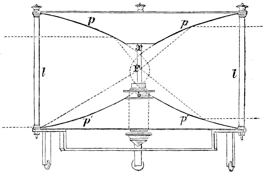
M. Bordier Marcet has also prepared an ingenious modification of the paraboloïdal mirror, which he has described under the name of Fanal à double effet. fanal à double effet; and the object of which is to obtain a convenient degree of divergence from parabolic mirrors, by the use of two flames and two reflecting surfaces, each of which is acted upon by its own flame, and also by that of the other. This modification consists in the union of two portions of hollow paraboloïdal mirrors, generated by the revolution of two parabolas about a common horizontal axis, and illuminated by two lamps placed in the focus of each. The first surface is generated by the revolution on its axis of a segment of a paraboloid intercepted between the parameter and some double ordinate greater than it, and may, from its form, be called the ribbon-shaped mirror. The second surface is that of a parabolic conoid, which is cut off by a vertical plane passing through a double ordinate, which is equal to the parameter of the parabolic ribbon, which is placed in front of it. The elements of the curve which forms the conoïdal mirror, must be so chosen as to have its focus at a convenient distance in front of that of the ribbon-shaped mirror, so as to admit of placing the two lamps separate from each other, as well as to produce the necessary degree of divergence, which is to be obtained by the action of these mirrors respectively on the flame placed in the focus of the other. These two mirrors are joined together in the line of the parametric section of the ribbon, which coincides with the lips of the conoid at some double ordinate behind its parameter. Each mirror produces, by means of the lamp placed in its focus, an approach to parallelism of the reflected rays, which M. Bordier Marcet has not inaptly termed the principal effect; whilst the action of each surface on the lamp which is placed in the focus of the other, causes what the inventor calls the secondary or lateral effect. Their secondary action may be described thus: The lamp, which is in the focus of the ribbon, is much nearer the vertex of the conoid than its own focus; so that its rays making, with normals to the surface of the conoid, angles greater than those which are formed by the rays proceeding from its focus, are of necessity reflected in lines diverging from the axis of the mirror. Those, on the contrary, which proceed from the focus of the conoid, meet the ribbon-shaped surface, so as to make angles with its normals more acute than those which the rays from its own focus could do, and which are, therefore, reflected in lines converging to the axis of the mirror. Those reflected rays must therefore cut the axis, and diverge from it on the other side. This apparatus has been used at La Hève and some other lights on the French coast; but it is impossible not to perceive the great loss of light which results from the use of two flames in one mirror; and it must not be forgotten, that the divergence which is obtained by means of it is not confined to the horizontal direction in which only it is wanted; but that the light is at the same time scattered in every direction round the edge of the mirror.
Arrangements of a similar kind were proposed and executed for the same purpose of uniting greater divergence with considerable power in the central parts of the resultant beam, by Argand himself, in 1806, and also in 1808, by M. Haudry, Ingénieur des Ponts et Chaussées. Argand proposed the union of a paraboloid, and an ellipsoid having their foci coincident in one point, which being the posterior focus of the latter curve, was illuminated by the rays reflected to it by means of the ellipsoïdal surface from the lamp placed in the anterior focus. From the optical focus thus obtained, some rays would fall on the paraboloïdal surface and produce, by reflection, a cylinder of parallel rays, while the rest would diverge from the axis, and form a zone of spreading rays. M. Haudry’s plan consisted of a combination of a conical with a paraboloïdal mirror, so placed, that the rays from the front part of the hollow cone might be nearly parallel to those sent out by the paraboloid; while the rays from its base diverging from the axis might produce a ring of divergent rays, similar to that obtained from the ellipsoid of Argand’s apparatus.
It would occupy much time to exhibit all the disadvantages of the arrangements in the fanal à double effet of M. Bordier Marcet, and also in those of Argand and Haudry; and I shall therefore dismiss the subject by observing, that the loss of light due to the position of the flame in the apparatus of Argand, is so great as to induce one to wonder that such combinations should ever have been attempted. There can be no doubt, that the most efficient mode of obtaining due divergence from mirrors, is to adopt the paraboloid, with a short focal distance, which has the double advantage of increasing the divergence which is due inversely to the focal distance, and, at the same time, subjecting to the action of the mirror a larger portion of the luminous sphere proceeding from the flame.
Fig. 46.
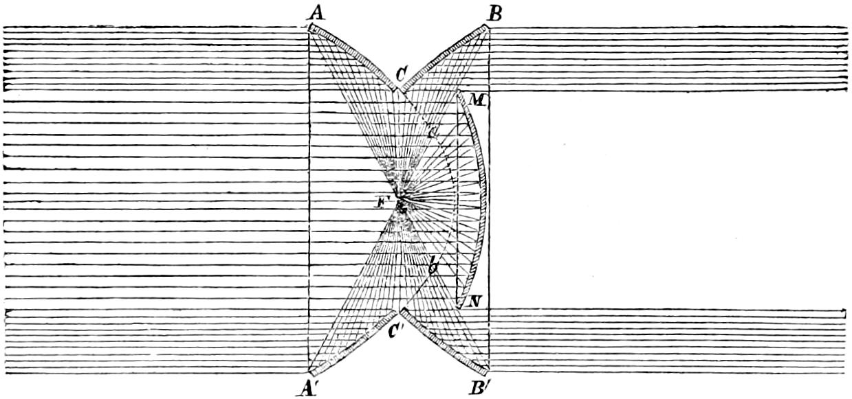
Fanal à double face. Lastly, I shall notice M. Bordier Marcet’s fanal à double face, which consists of two paraboloïdal mirrors, truncated in the vertical plane of the parameter, and united together back to back, so as to be illuminated by the same lamp placed in their common focus. To save the light which would otherwise escape the catoptric action, he adds a parabolic conoid of greater focal distance, and so placed, that while its focus may coincide with the common focus of the other mirrors, its size may be so restricted, that it shall not interfere with the effect of the truncated mirror opposite which it is placed. The obvious consequence of such an arrangement is, that the rays (see fig. 46) produced from a lamp in the common focus of the three mirrors, will produce in opposite directions a luminous ring from each of the truncated mirrors AC, BC, and A′C′, B′C′, while the central or conoïdal mirror MN will fill the interior of one of those luminous rings with a cone of rays, whose intensity will be in the inverse ratio of MN² to a b² (or FM² to F a²), which latter surface represents the whole amount of naturally divergent rays, which strike on a b, and which are spread over MN. Two sets of reflectors of this form facing in opposite directions (each set arranged in one plane, and fixed on a frame which could be made to revolve round a vertical axis), would thus present their brightest effect after considerable intervals of darkness; but, by arranging them with their axes slightly inclined, they were made to prolong the light periods and curtail the dark ones. M. Bordier Marcet speaks of this apparatus with all the satisfaction generally felt by inventors; but it is no difficult matter to identify its effect with that of the common paraboloïdal mirrors. It is obvious, that all the rays which fall from a true focal point on the three reflectors AC, BC, A′C′, B′C′, and MN, are merely those which would fall on a single reflector, whose double ordinate and the portion of the abscissa between that ordinate and the focus, are equal to those of the first reflector of the compound system, so that the quantity of light reflected by the three reflectors is neither more nor less than that which would be projected by one. All the difference that can exist is, that in the case of a flame which has a notable size, the surface MN being farther distant than a b, would produce less aberration and, consequently, a very slight increase of intensity in the small portion of the reflected beam of parallel rays due to that part of the compound mirror. We cannot, therefore, sensibly err in rejecting any advantage to be derived from this arrangement as insignificant.[47]
Spherical mirrors have been employed in Lighthouses chiefly when they can be introduced to aid the effect of refracting apparatus: and it will not be necessary to say much of them in this place. I must, however, notice an ingenious proposal of Mr Barlow′s Spherical Mirrors. Mr W. H. Barlow,[48] who suggests placing in front of the flame a small spherical reflector, whose centre is coincident with the focus of a paraboloïd, and whose subtense is the parameter of the generating curve. The small mirror, being somewhat less than a hemisphere, would cause the light falling upon it to be returned through the focus so as to reach the paraboloïdal surface and to be finally reflected from that portion of it which is embraced between the limits of its extreme divergence. If there were no loss of light at the surface of the small mirror, its effect would be to increase the power of the beam of parallel rays by an amount equal to the sum of the rays incident on the spherical surface, but at the same time to diminish it by intercepting a portion of the light reflected from the paraboloïd. I am not aware that such a combination has been tried, as it applies most advantageously to reflectors whose span does not exceed the parameter of the generating curve, a form rarely adopted in lighthouses; but it might also be adapted to reflectors which intercept a larger portion of light, by making the spherical reflector some segment less than the hemisphere.
Captain Smith’s Mirrors in the form of a parabolic spindle. Captain Smith of the Madras Engineers, has described in the “Professional papers of the ‘Corps of Royal Engineers,’[49] a new system of fixed lights,” which consists in placing a flat wick in the focus of one-half of a hollow parabolic spindle generated by the rotation of a parabola about its parameter as a vertical axis. The action of the instrument is obvious, for each vertical section being parabolic, effects a change only in the vertical divergence of the rays incident on it from the focus, and suffers their horizontal direction to remain unaltered; thus each vertical plate of reflected rays passes through the parameter of the curve and illuminates the opposite point of the horizon by means of a narrow strip or line of light. Two hollow spindles of that form, each lighting 180° and facing opposite azimuths, would, therefore, be sufficient to illuminate the whole horizon. The author of the paper, however, appears to contemplate the employment of a series of those mirrors ranged one above another and breaking joint vertically, somewhat in the manner already described in speaking of the arrangement of the paraboloïdal mirrors used in fixed lights. The advantages of this mode of illumination are much overrated by Captain Smith, who seems to magnify beyond its real importance the risk attending the use, in the dioptric apparatus, of a single lamp, whose sudden extinction would deprive at once the whole horizon of the benefit of the light; while, on the contrary, he reckons the security obtained by his arrangement as an advantage of the highest value. In certain situations, where no regular establishment of trained light-keepers is maintained, that security may be an object of more importance and may warrant a greater sacrifice, than is necessary in Great Britain; but I have no hesitation in saying, that I know of no situation in which the plan proposed by Captain Smith could bear comparison with the mode of illumination for fixed lights by means of the catadioptric instruments of Fresnel.
DIOPTRIC[50] SYSTEM OF LIGHTS.
One of the earliest notices of the application of lenses to lighthouses is that recorded by Smeaton in his Narrative of the Eddystone Lighthouse, where he mentions a London optician, who, in 1759, proposed grinding the glass of the lantern to a radius of seven feet six inches; but the description is too vague to admit of even a conjecture regarding the proposed arrangement of the apparatus. About the middle of the last century, however, lenses were actually tried in several lighthouses in the south of England, and in particular at the South Foreland in the year 1752; but their imperfect figure and the quantity of light absorbed by the glass, which was of impure quality and of considerable thickness, rendered their effect so much inferior to that of the parabolic reflectors then in use, that after trying some strange combinations of lenses and reflectors, the former were finally abandoned. Lenses were also tried at the lights of Portland, Hill of Howth, and Waterford, by Mr Thomas Rogers, a glass manufacturer in London; who possessed, it is said, the art of blowing mirrors of glass, “and by a new method silvered over the convex side without quicksilver.”[51]
The object to be attained by the use of lenses in a Lighthouse is, of course, identical with that which is answered by employing reflectors; and both instruments effect the same end by different means, collecting the rays which diverge from a point called the focus, and projecting them forward in a beam, whose axis coincides with the produced axis of the instrument. We have already seen that, in the case of reflection, this result is produced by the light being thrown back from a surface so formed as to make all the rays to proceed in one and the same required direction. In the case of refraction, on the other hand, the rays pass through the refracting medium, and are bent or refracted from their natural course into that which is desired.
The celebrated Buffon, to prevent the great absorption of light by the thickness of the material, which would necessarily result from giving to a lens of great dimensions a figure continuously spherical, proposed to grind out of a solid piece of glass, a lens in steps or concentric zones. This suggestion of Buffon regarding the construction of large burning glasses, was first executed, with tolerable success, about the year 1780, by the Abbé Rochon; but such are the difficulties attending the process of working a solid piece of glass into the necessary form, that it is believed the only other instrument ever constructed in this manner, is that which was made by Messrs Cookson of Newcastle-upon-Tyne, for the Commissioners of Northern Lighthouses.
The merit of having first suggested the building of lenses in separate pieces, seems to be due to Condorcet, who, in his Eloge de Buffon, published so far back as 1773, enumerates the advantages to be derived from this method. Sir David Brewster also described this mode of building lenses in 1811, in the Edinburgh Encyclopædia; and in 1822, the late eminent Fresnel, unacquainted with the suggestions of Condorcet or the description by Sir David Brewster, explained, with many ingenious and interesting details, the same mode of constructing those instruments. To Fresnel belongs the additional merit of having first followed up his invention, by the construction of a lens and, in conjunction with MM. Arago and Mathieu, of placing a powerful lamp in its focus, and indeed of finally applying it to the practical purposes of a Lighthouse.
The great advantages which attend the mode of construction proposed by Condorcet are,—the ease of execution, by which a more perfect figure may be given to each zone and spherical aberration in a great measure corrected, and the power of forming a lens of larger dimensions than could easily be made from a solid piece. Both Buffon and Condorcet, however, chiefly speak of reducing the thickness of the material, and do not seem to have thought of determining the radius and centre of the curvature of the generating arcs of each zone, having contented themselves with simply depressing the spherical surface in separate portions. Fresnel, on the other hand, determined those centres, which constantly recede from the vertex of the lens in proportion as the zones to which they refer are removed from its centre; and the surfaces of the zones of the annular lens, consequently, are not parts of concentric spheres, as in Buffon’s lens. It deserves notice, that the first lenses constructed for Fresnel by M. Soleil had their zones polygonal, so that the surfaces were not annular, a form which Fresnel considered less accommodated to the ordinary resources of the optician. He also, with his habitual penetration, preferred the plano-convex to the double-convex form, as more easily executed.[52] After mature consideration, he finally adopted crown glass, which, notwithstanding its greenish colour, he preferred to flint glass, as being more free from striæ. All his calculations were made in reference to an index of refraction of 1·51, which he had verified by repeated experiments, conducted with that patience and accuracy for which, amidst his higher qualities, he was so remarkably distinguished.[53] The instruments have received the name of annular lenses, from the figure of the surface of the zones.
A ray of light, in passing obliquely from one transparent body into another of different density, experiences at the point of the intersection of the common surface of the two planes, a sudden change of direction, to which the name of Refraction. refraction has naturally been given, in connection with the most familiar instance of the phenomenon, which is exhibited by a straight ruler with one half plunged into a basin of water while the other remains in the air. The ruler no longer appears straight, but seems to be bent or broken at the point where it enters the water. It may not be out of place to call attention to the laws which regulate the change of direction in the incident light, which are three in number.
1. Incidence and refraction, in uncrystallized media of homogeneous structure such as glass, always occur in a plane perpendicular to that of the refracting surface.
2. In the same substances, the angle formed with the perpendicular by the ray at its entering the surface of the second medium, has to the angle which it makes with the normal after it has entered the surface, such a relation, that their sines have a fixed ratio, which is called the refractive index. When a ray falls normally on the surface of any substance, it suffers no refraction.
3. The effect of passing from a rare to a dense medium, as from air into water or glass, is to make the angle of refraction less than the angle of incidence; and those angles are measured with reference to a normal to the plane which separates the media at the point of incidence. The converse phenomenon, of course, takes place in the passage from a dense to a rare medium, in which case the angle of incidence is less than the angle of refraction. To this rule there are a few exceptions; for there are certain combustible bodies, such as diamond, whose refractive powers are much greater than other substances of equal density.
Fig. 47.
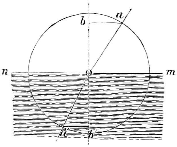
The diagram (fig. 47) will serve to render those laws more intelligible. Let a ray of light a O meet a surface of water n m at O, it will be immediately bent into the direction O a′; and if, from the centre O, we describe any circle, and draw a line b O b′, perpendicular to nm; then ab and a′ b′, perpendiculars drawn to the normal bb′, from the points a and a′ where the circle cuts the incident and refracted rays, will be the sines of the angle of incidence b O a, and of the angle of refraction b′ O a′, and the ratio of those sines to each other, or b ab′ a′ will be the relative index of refraction for the two media.
4. It may perhaps be added, for convenience, as a fourth law, deducible from the others, that since rays passing from a dense into a rare medium, have their angle of refraction greater than the angle of incidence, there must be some angle of incidence whose corresponding angle of refraction is a right angle; beyond which no refraction can take place, because there is no angle whose sine can be greater than the radius. In such circumstances, total reflection ensues. For common glass, whose index of refraction is 1·5, we have (in the case of emergent rays) sine of incidence = sine of refraction1·5; but, as no sine can exceed radius or unity, the angle of incidence must be limited to 41° 49′; beyond which total reflection will take place, and the light will return inwards into the glass, being reflected at its surface.
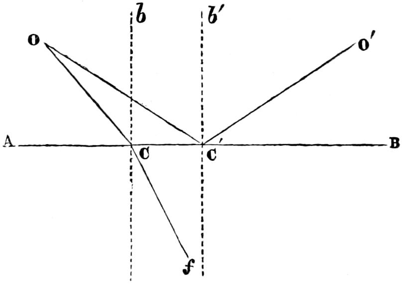
Thus, if a ray proceed from a point O (fig. 48), within a piece of glass, to a point C, at its surface A B; and if O C b, its incidence, be less than 41° 49′, it will be refracted in some direction C f; but if this angle be greater than 41° 49′, as O C′ b′, the ray will be reflected back into the glass in the direction C′ O′.
Fig. 48.
The material hitherto employed in the construction of lighthouse apparatus is crown glass, which, although it possesses a lower refractive power than flint glass and has, besides, a slightly greenish tinge, offers the great practical advantages of being more easily obtained of homogeneous quality; and, being less subject to deterioration from atmospheric influences, it is peculiarly suitable for use in the exposed situations generally occupied by Lighthouses. The refractive index of crown glass, as already noticed, is about 1·5.
Any one may easily satisfy himself by a careful protraction of the angles of incidence and refraction, in the manner above described, as to the truth of the following general propositions resulting from those laws:—
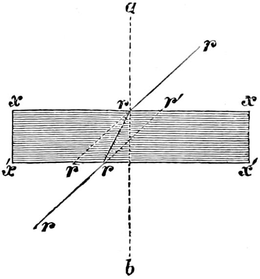
1. A ray of light passing through a plate of some diaphanous substance such as glass, with parallel surfaces, suffers no change of direction, but emerges in a line parallel to its original path, merely suffering a displacement, depending on the obliquity of the incident ray, and the refractive power and thickness of the plate. The effect of this displacement is merely to give the ray an apparent point of origin different from the true one. This will be easily understood by the diagram (fig. 49), in which a b is a normal to the plate, whose surfaces x x and x′ x′ are parallel, r r r r shews the path of the ray, r r the displacement, and r′ the apparent point of origin resulting from its altered direction.
Fig. 49.
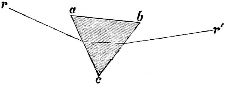
2. When a ray passes through a triangular prism a b c, the inclination of the faces a c and c b causes the emergent ray r′ to be bent towards a b, the base of the prism, in a measure depending on the inclination of the sides of the prism and the obliquity of the incident ray to the first surface.
Fig. 50.
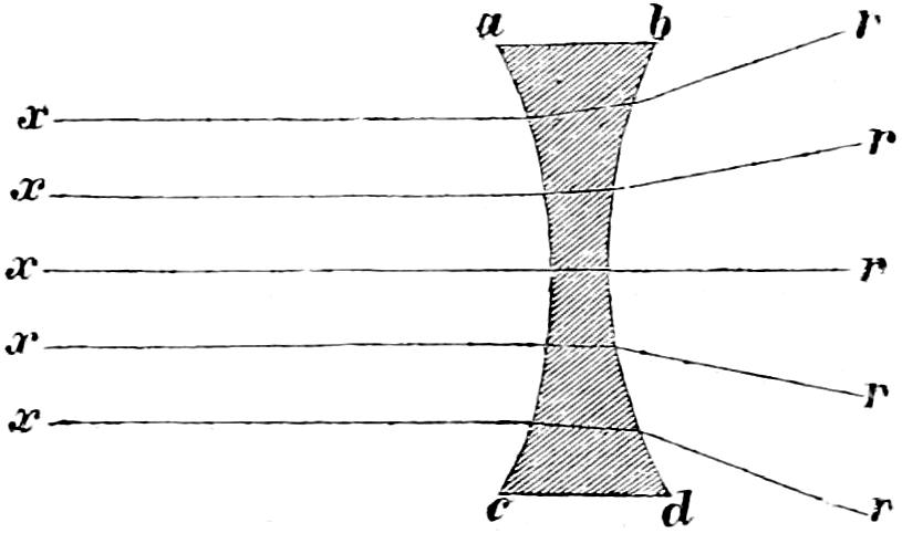
3. When parallel rays fall on a concave lens, they will, at their emergence, be divergent. The section of the diaphanous body a b c d may be regarded as composed of innumerable frusta of prisms, having their apices directed towards the centre line x r; and the rays which pass through the centre, being normal to the surface, will be unchanged in their direction, while all the others will (as shewn in the figure) suffer a change of direction, increasing with their distance from the centre, owing to the increasing inclination of the surfaces of the lens as they recede from its axis.
Fig. 51.
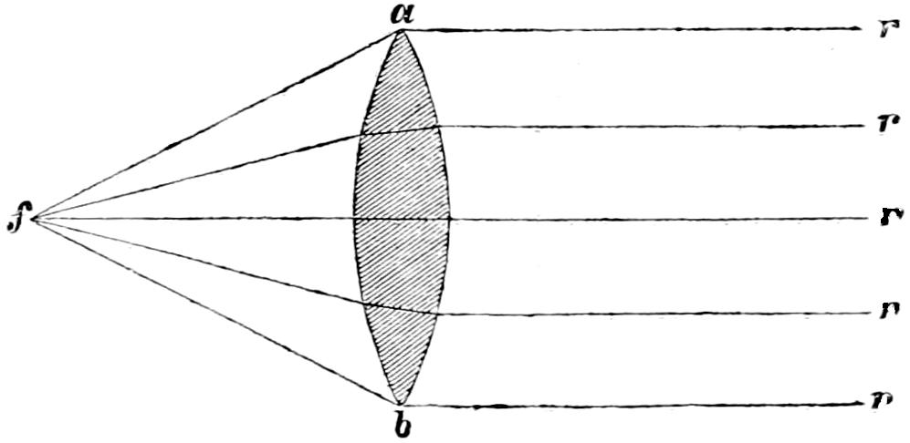
4. Lastly, when divergent rays fall on a convex lens a b, from a point f, called the principal focus, they are made parallel at their emergence; while, conversely, parallel rays which fall on the lens are united in that point.[54] This effect, which is the opposite of that caused by the concave lens, may be explained in a similar manner, by conceiving the section a b of the convex lens to be composed of innumerable frusta of prisms, arranged with their bases towards the centre of the lens.
Fig. 52.
Now, it is obvious, that we can derive no assistance, in economising the rays of a lamp for Lighthouse purposes, from concave lenses, whose property is to increase the dispersion of the rays incident on them. With concave lenses, therefore, we have no concern; and we shall confine ourselves to the consideration of the convex or converging lenses.
The lens always used in Lighthouses is (for reasons already noticed) plano-convex, and differs from the last only by having a plane and a curve surface, instead of two curve surfaces, whose radii are on opposite sides of the lens. The plano-convex is generally regarded, by writers on optics, as a case of the double convex having one side of an infinite radius. Both forms cause parallel rays to converge to a focus.
We commence with a general view of the relations which exist between the position of the radiant and the focus.
Fig. 53.
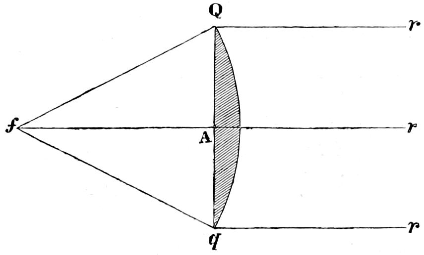
Let Q q be a section of a lens, and f A r its optical axis, or the line in which a ray of light passes unchanged in its direction through the lens, from its being normal to both surfaces, whether the lens be double-convex as above, or plano-convex (see fig. 53), then the principal focus f is that point where the rays from r r r, which fall parallel to the optic axis on the outer face of the lens, meet after refraction at the two faces,—or, to speak more in the language of the art which is under consideration, the principal focus f is the point whence the rays of light, proceeding in their naturally divergent course, fall on the inner surface Q A q of the lens, and are so changed by refraction there and at the outer face, that they finally emerge parallel to the optic axis in the directions Q r, q r. The position of this point depends partly on the refractive power of the substance of which the lens is composed and partly on the curvature of the surface or surfaces which bound it.
It would be quite beyond the scope of these Notes to attempt to present the subject of refraction at spherical surfaces before the reader’s view in a rigorous or systematic manner, and thus to advance, step by step, to the practical application of refracting instruments, as a means of directing and economising the light in a Pharos. This would involve the repetition, in a less elegant form, of what is to be found in all the works on optics; and instead of this, I am content to refer, where needful, to those works, and shall confine myself simply to what concerns Lighthouse lenses and their use. It would also be superfluous to determine the position of the principal focus of a plano-convex lens, in terms of the refractive index and radius of curvature,[55] as it can be very accurately found in practice by exposing the instrument to the sun, in such a manner that his rays may fall upon it in a direction parallel to its axis. The point of union between the converging and diverging cones of rays (where the spectrum is smallest and brightest), which is the principal focus, is easily found by moving a screen behind the lens, farther from or nearer to it as may be required. The path of the Lighthouse optician, moreover, generally lies in the opposite direction; and his duty is not so much to find the focal distance of a ready-made lens, as to find the best form of a lens for the various circumstances of a particular Pharos, whose diameter, in some measure, determines the focal distance of the instruments to be employed. All, however, that I shall really have to do is to give an account of what has been done by the late illustrious Fresnel, who seems to have devoted such minute attention to every detail of the Dioptric apparatus, that he has foreseen and provided for every case that occurs in the practice of Lighthouse illumination. His brother, Mons. Leonor Fresnel, who succeeded him in the charge of the Lighthouses of France, has, with the greatest liberality, put me in possession of the various formulæ used by his lamented predecessor, in determining the elements of those instruments which have so greatly improved the lighthouses of modern days.
Spherical lenses, like spherical mirrors, collect truly into the focus those rays only which are incident near the axis; and it is, therefore, of the greatest importance to employ only a small segment of any sphere as a lens. The experience of this fact, among other considerations, led Condorcet, as already noticed, to suggest the building of lenses in separate pieces. Fresnel, however, was the first who actually constructed a lens on that principle; and he has subdivided, with such judgment, the surface of the lens into a centre lens and concentric annular bands and has so carefully determined the elements of curvature for each, that no farther improvement is likely to be made in their construction. For the drawings of the great lens, I have to refer to Plate XII., which also contains a tabular view of the elements of its various parts. The central disc of the lens, which is employed in lights of the first order, and whose focal distance is 920 millimètres, or 36·22 inches, is about 11 inches in diameter; and the annular rings which surround it vary slightly in breadth from 2³⁄₄ to 1¹⁄₄ inches. The breadth of any zone or ring is, within certain limits, a matter of choice, it being desirable, however, that no part of the lens should be much thicker than the rest, as well for the purpose of avoiding inconvenient projections on its surface, as to permit the rays to pass through the whole of the lens with nearly equal loss by absorption. The objects to be attained in the polyzonal or compound lens, are chiefly, as above noticed, to correct the excessive aberration produced by refraction through a hemisphere or great segment, whose edge would make the parallel rays falling on its curve surface converge to a point much nearer the lens than the principal focus, as determined for rays near the optical axis, and to avoid the increase of material, which would not only add to the weight of the instrument and the expense of its construction, but would greatly diminish by absorption the amount of transmitted light. Various modes of removing similar inconveniences in telescopic lenses have been devised; and the suggestions of Descartes, as to combinations of hyperbolic and elliptic surfaces with plane and spherical ones, more especially fulfil the whole conditions of the case; but the excessive difficulty which must attend grinding and polishing those surfaces, has hitherto deprived us of the advantages which would result from the use of telescopic lenses entirely free from spherical aberration. In Lighthouse lenses, where so near an approach to accurate convergence to a single focus is unnecessary, every purpose is answered by the partial correction of aberration which may be obtained, by determining an average radius of curvature for the central disc, and for each successive belt or ring, as you recede from the vertex of the lens. In the lenses originally constructed for Fresnel by Soleil, the zones were united by means of small dowels or joggles of copper, passing from the one zone into the other; but the greater exactness of the workmanship now attained, has rendered it safe to dispense with those fixtures; and the compound lens is now held together solely by a metallic frame and the close union between the concentric faces of the rings, which, however, are in contact with each other at surfaces of only ¹⁄₄ inch in depth, as shewn in Plate XII. It is remarkable, that an instrument, having about 1300 square inches of surface, and weighing 109 lb., and which is composed of so many parts, should be held together by so slender a bond as two narrow strips of polished glass, united by a thin film of cement.
I now proceed to the formulæ employed by Fresnel, to determine the elements of the compound lens,[56] in the calculation of which two cases occur, viz., the central disc and a concentric ring. The focal distance of the lens and the refractive index of the glass are the principal data from which we start.
Fig. 54.
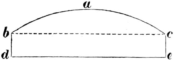
I begin with the case of the central disc or lens round which the annular rings are arranged. Its principal section is a mixtilinear figure (fig. 54) composed of a segment b a c, resting on a parallelogram b c d e, whose depth b d or c e is determined by the strength which is required for the joints which unite the various portions of the lens. Those particulars have, as I already stated, been determined with so much judgment by Fresnel and the dimensions of the lenses so varied to suit the case of various lights, that nothing in this respect remains to be done by others.
Fig. 55.
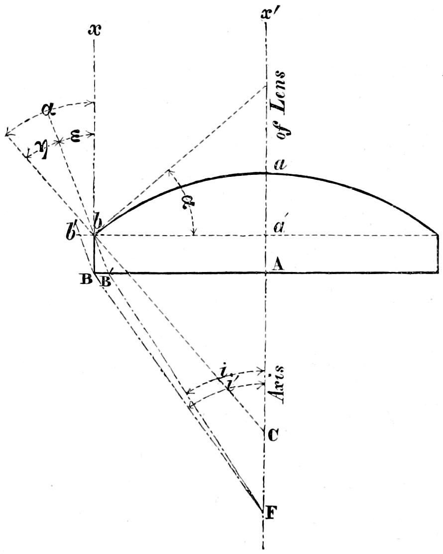
Referring to fig. 55, we have, for obtaining the radius of the central disc, the following formulæ, in which
r = AB, half the aperture of the lens
r′ = AB′
φ = AF, the focal distance
t′ = A a, the thickness of the lens at the vertex
t″ = B b, the thickness of the joint
μ = the index of refraction
ρ = the radius of curvature.
Then for the radius of curvature near the axis we have:
ρ′ = (μ - 1)(φ + t′μ)
and for that near the margin we have:
tan i′ = rφ sin e = sin i′μ r′ = r - t″ . tan e tan i = r′φ sin ε = sin iμ
ρ″ = rμ sin e √μ² - 2 μ cos e + 1
and, finally ρ = ρ′ + ρ″ 2[57]
Fig. 58.
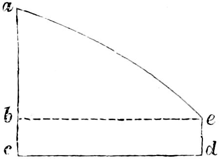
I come next to the second case, which concerns the calculation of the elements of a concentric ring. The section a b c d e (fig. 58) of one of those rings includes a mixtilinear triangle a b e, and a rectangle b c e d, the thickness b c being the same as that of the edge of the central disc; and the elements to be determined are the radius of the curve surface, and the position of the centre of curvature, with reference to the vertex of the lens.
Fig. 59.
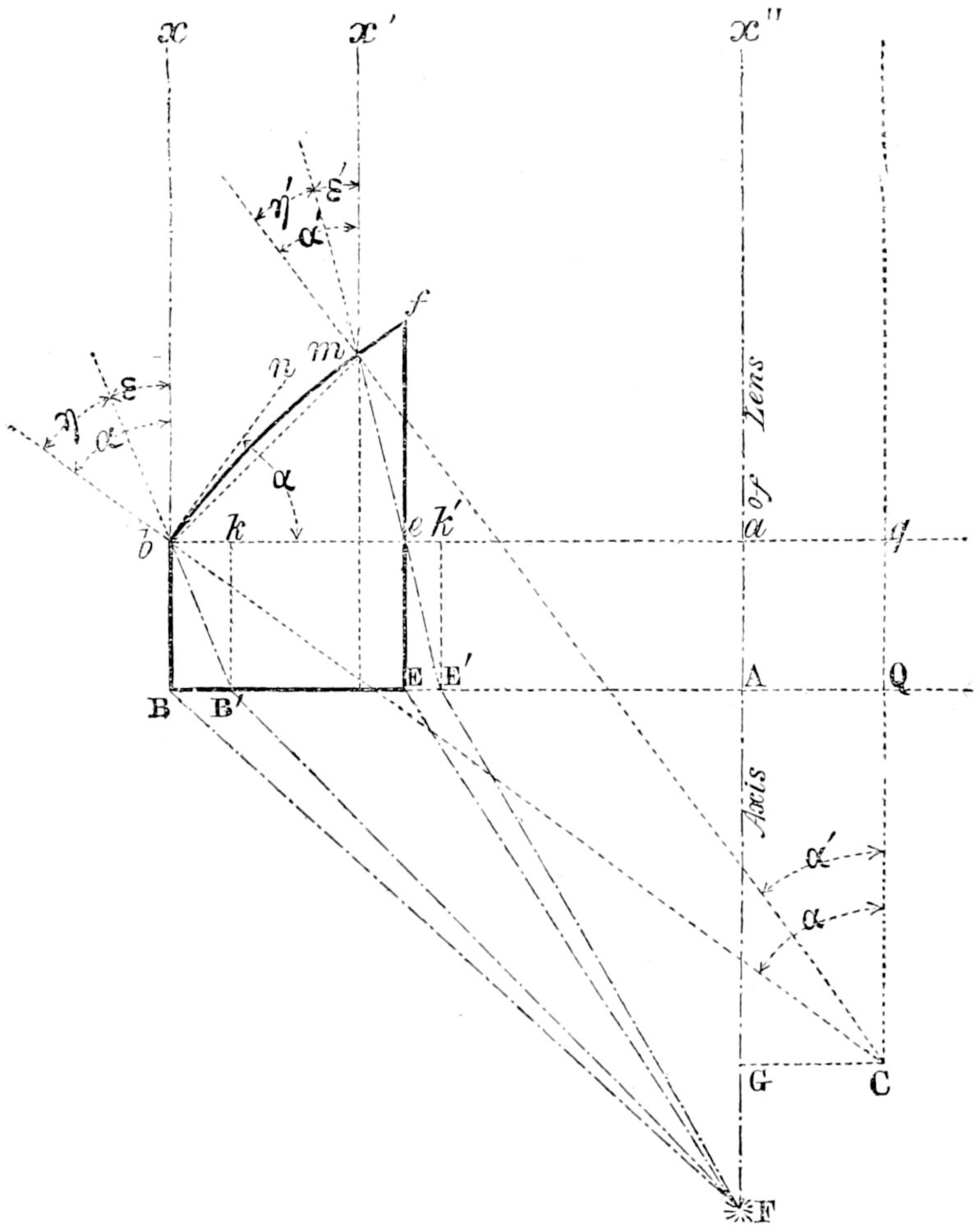
The radius of curvature of the zone may be calculated by the following formulæ, in which (see fig. 59)
r₁ = AB the distance of the outer margin of the zone from the axis of the lens
r₂ = AE the distance of the inner margin from the axis
l = BE the breadth of the zone = r₁ - r₂
ρ = the radius of curvature = b C = m C
φ = focal distance AF
t = thickness of the joint B b
t″ = B b
μ = refractive index of the glass
i₁ = BFA
i₂ = EFA
Then tan i′₁ = r₁φ; tan i′₂ = r₂φ
sin e₁ = sin i′₁μ; sin e₂ = sin i′₂μ
r′₁ = r₁ - t″ sin e₁; r′₂ = r₂ - t″ sin e₂
tan i₁ = r′₁φ; tan i₂ = r′₂φ
sin ε = sin i₁μ; sin ε′ = sin i₂μ
sin α = μ sin ε √μ² - 2 μ cos ε + 1;
sin α′ = μ sin ε′ √μ² - 2 μ cos ε′ + 1; η = α′ - ε′
and lastly ρ = 2 cos ε′ 2 cos {η + ¹⁄₂(α - α′)} sin ¹⁄₂ (α - α′)
which is Fresnel’s value of the radius of curvature.[58]
Lastly, the position of C the centre of curvature for a ring is easily determined by two co-ordinates in reference to their origin, A, which is the vertex of the lens (see fig. 60 below), by the equations:
CG = ρ . sin α - a b = ρ . sin α - r₁
CQ = ρ . cos α - q Q = ρ . cos α - t″
The elements of each successive zone are determined in the same manner. The annular lens of the first order of lights in Fresnel’s system consists, as already stated, of a central disc 11 inches in diameter, and 10 concentric rings, all of which have a common principal focus, where the rays of the sun meet after passing through the lens. With such accuracy are those rings and the disc ground and placed relatively to each other, that the position of the actual conjugate focus of the entire surface of the compound lens, differs in a very small degree from that obtained by calculation in the manner described below.[59]
In the combination of lenses with the flame of a lamp, similar considerations must influence us in making the necessary arrangements, as in the case of reflectors. We have already seen that the size of the flame and its distance from the surface of reflecting instruments have an important practical bearing on the utility of the instrument, Divergence of Annular Lenses. and that the divergence of the resultant beam materially affects its fitness for the purpose of a Lighthouse. So also, in the case of the lens, unless the diameter of the flame of the lamp has to the focal distance of the instrument a relation such as may cause an appreciable divergence of the rays refracted through it, it could not be usefully applied to a Lighthouse; for, without this, the light would be in sight during so short a time, that the seaman would have much difficulty in observing it. To determine the amount of this divergence of the refracted beam, therefore, is a matter of great practical importance, and I shall briefly point out the conditions which regulate its amount, as they are nearly identical with those which determine the divergence of a paraboloïdal mirror illuminated by a lamp in its focus. The divergence, in the case of lenses, may be described as the angle which the flame subtends at the principal focus of the lens, the maximum of which, produced at the vertex of Fresnel’s great lens by the lamp of four concentric wicks, is about 5° 9′.[60]
Illuminating Power of Lenses. On the subject of the illuminating power of the lenses, it seems enough to say, that the same general principle regulates the estimate as in reflectors. Owing to the square form of the lens, however, there is a greater difficulty in finding a mean focal distance whereby to correct our estimate of the angle subtended by the light, so as to equate the varying distance of the several parts of the surface; but, practically, we shall not greatly err if we consider the quotient of the surface of the lens divided by the surface of the flame as the increased power of illumination by the use of the lens. The illuminating effect of the great lens, as measured at moderate distances, has generally been taken at 3000 Argand flames, the value of the great flame in its focus being about 16, thus giving its increasing power as nearly equal to 180. The more perfect lenses have produced a considerably greater effect.
The application of lenses to Lighthouses is so obvious as scarcely to admit of farther explanation than simply to state, Arrangement of the Lenses in a Lighthouse. that those instruments are arranged round a lamp placed in their centre, and on the level of the focal plane in the manner shewn in Plates XIII. and XIV.,[61] so as to form by their union a right octagonal hollow prism, circulating round the flame which is fixed in the centre, and shewing to a distant observer successive flashes or blazes of light, whenever they cross a line joining his eye and the lamp, in a manner similar to that already noticed in describing the action of the mirrors. The chief difference in the effect consists in the greater intensity and shorter duration of the blaze produced by the lens; which latter quantity is, of course, proportional to the divergence of the resultant beam. Each lens subtends a central horizontal pyramid of light of about 46° of inclination, beyond which limits the lenticular action could not be advantageously pushed, owing to the extreme obliquity of the incidence of light; but Fresnel at once conceived the idea of pressing into the service of the mariner, by means of two very simple expedients, the light which would otherwise have uselessly escaped above and below the lenses.
For intercepting the upper portion of the light, Fresnel employed eight smaller lenses of 500 mm. focal distance (19·68 inches) inclined inwards towards the lamp, which is also their common focus and thus forming, by their union, Pyramidal Lenses and Mirrors. a frustum of a hollow octagonal pyramid of 50° of inclination. The light falling on those lenses is formed into eight beams parallel to the axis of the smaller lenses, and rising upwards at an angle of 50° inclination. Above them are ranged eight plane mirrors, so inclined (see Plates XIII. and XIV.) as to project the beams transmitted by the small lenses in the horizontal direction, so as finally to increase the effect of the light. In placing those upper lenses, it is generally thought advisable to give their axis an horizontal deviation of 7° or 8° from that of the great lenses and in the direction contrary to that of the revolution of the frame which carries the lenticular apparatus. By this arrangement, the flashes of the smaller lenses precede that of the large ones, and thus tend to correct the chief practical defect of revolving lenticular lights by prolonging the bright periods. The elements of the subsidiary lenses depend upon the very same principles, and are calculated by the same formulæ as those given for the great lenses. In fixing the focal distance and inclination of those subsidiary lenses, Fresnel was guided by a consideration of the necessity for keeping them sufficiently high to prevent interference with the free access to the lamp. He also restricted their dimensions within very moderate limits, so as to avoid too great weight. The focal distance is the same as that for lenses of the third order of lights.
Fig. 65.
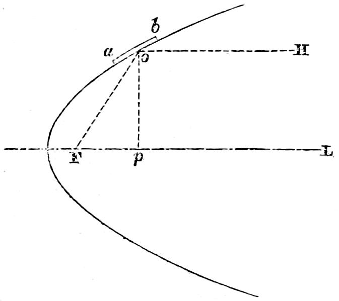
Owing to the necessary arrangements of a lantern, only a very small portion of those rays, which escape from below the lenses, can be rendered available for the purposes of a Lighthouse; and any attempt to subject it to lenticular action, so as to add it to the periodic flashes, would have led to a most inconvenient complication of the apparatus. Fresnel adopted the more natural and simple course of transmitting it to the horizon in the form of flat rings of light, or rather of divergent pencils, directed to various points of the horizon. Curved Mirrors. This he effected by means of small curved mirrors, disposed in tiers, one above another, like the leaves of a Venetian blind—an arrangement which he also adopted (shewn in Plates XV. and XVI.) for intercepting the light which escapes above as well as below the dioptric belt in fixed lights. Those curved mirrors are, strictly speaking, generated (see fig. 65) by portions, such as a b, of parabolas, having their foci coincident with F, the common flame of the system. In practice, however, they are formed as portions of a curved surface, ground by the radius of the circle, which osculates the given parabolic segment.[62] The mirrors are plates of glass, silvered on the back and set in flat cases of sheet-brass. They are suspended on a circular frame by screws, which are attached to the backs of the brass cases, and which afford the means of adjusting them to their true inclination, so that they may reflect objects on the horizon of the Lighthouse to an observer’s eye, placed in the common focus of the system.[63]
Cylindric Refractors for Fixed Lights. Having once contemplated the possibility of illuminating Lighthouses by dioptric means, Fresnel quickly perceived the advantage of employing for fixed lights a lamp placed in the centre of a polygonal hoop, consisting of a series of refractors, infinitely small in their length and having their axes in planes parallel to the horizon. Such a continuation of vertical sections, by refracting the rays proceeding from the focus, only in the vertical direction, must distribute a zone of light equally brilliant in every point of the horizon. This effect will be easily understood, by considering the middle vertical section of one of the great annular lenses, already described, abstractly from its relation to the rest of the instrument. It will readily be perceived that this section possesses the property of simply refracting the rays in one plane coincident with the line of the section and in a direction parallel to the horizon, and cannot collect the rays from either side of the vertical line; and if this section, by its revolution about a vertical axis, becomes the generating line of the enveloping hoop, above noticed, such a hoop will of course possess the property of refracting an equally diffused zone of light round the horizon. The difficulty, however, of forming this apparatus appeared so great, that Fresnel determined to substitute for it a vertical polygon, composed of what have been improperly called cylindric lenses, but which in reality are mixtilinear and horizontal prisms, distributing the light which they receive from the focus nearly equally over the horizontal sector which they subtend. This polygon has a sufficient number of sides to enable it to give, at the angle formed by the junction of two of them, a light not very much inferior to what is produced by one of the sides; and the upper and lower courses of curved mirrors are always so placed as partly to make up for the deficiency of the light at the angles. The effect sought for in a fixed light is thus obtained in a much more perfect manner, than by any combination of the parabolic mirrors used in the British Lighthouses.
Application of crossed prisms to cause occasional flashes.An ingenious modification of the fixed apparatus is also due to the inventive mind of Fresnel, who conceived the idea of placing one apparatus of this kind in front of another, with the axis of the cylindric pieces crossing each other at right angles. As those cylindric pieces have the property of refracting all the rays which they receive from the focus, in a direction perpendicular to the mixtilinear section which generates them, it is obvious that if two refracting media of this sort be arranged as above described, their joint action will unite the rays which come from their common focus into a beam, whose sectional area is equal to the overlapped surface of the two instruments, and that they will thus produce, although in a disadvantageous manner, the effect of an annular lens. It was by availing himself of this property of crossed prisms, that Fresnel invented the distinction for lights, which he calls a fixed light varied by flashes; in which the flashes are caused by the revolution of cylindric refractors with vertical axes, ranged round the outside of the fixed light apparatus already described.
Having been directed by the Commissioners of the Northern Lighthouses to convert the fixed catoptric light of the Isle of May, into a dioptric light of the first order, I proposed, that an attempt should be made True Cylindric form given to the Refractors and other improvements in their Construction. to form a true cylindric, instead of a polygonal belt for the refracting part of the apparatus; and this task was successfully completed by Messrs Cookson of Newcastle in the year 1836. The disadvantage of the polygon lies in the excess of the radius of the circumscribing circle over that of the inscribed circle, which occasions an unequal distribution of light between its angles and the centre of each of its sides; and this fault can only be fully remedied by constructing a cylindric belt, whose generating line is the middle mixtilinear section of an annular lens, revolving about a vertical axis passing through its principal focus. This is, in fact, the only form which can possibly produce an equal diffusion of the incident light over every part of the horizon.
I at first imagined that the whole hoop of refractors might be built between two metallic rings, connecting them to each other solely by the means employed in cementing the pieces of the annular lenses; but a little consideration convinced me that this construction would make it necessary to build the zone at the lighthouse itself, and would thus greatly increase the risk of fracture. I was therefore reluctantly induced to divide the whole cylinder into ten arcs, each of which being set in a metallic frame, might be capable of being moved separately. The chance of any error in the figure of the instrument has thus a probability of being confined within narrower limits; whilst the rectification of any defective part becomes at the same time more easy. One other variation from the mode of construction at first contemplated for the Isle of May refractors, was forced upon me by the repeated failures which occurred in attempting to form the middle zone in one piece; and it was at length found necessary to divide this belt by a line passing through the horizontal plane of the focus. Such a division of the central zone, however, was not attended with any appreciable loss of light, as the entire coincidence of the junction of the two pieces with the horizontal plane of the focus, confines the interception of the light to the fine joint at which they are cemented. With the exception of those trifling changes, the idea at first entertained of the construction of the instrument was fully realised at the manufactory of Messrs Cookson. I also, at a subsequent period, greatly improved the arrangement of this apparatus, by giving to the metallic frames which contain the prisms, a rhomboidal,[64] instead of a rectangular form. The junction of the frames being thus inclined from the perpendicular, do not in any azimuth intercept the light throughout the whole height of the refracting belt, but the interception is confined to a small rhomboidal space, whose area is inversely proportional to the sine of the angle of inclination; and if the helical joints be formed between the opposite angles of the old rectangular frames, the amount of intercepted light becomes absolutely equal in every azimuth.[65]
Fig. 70.
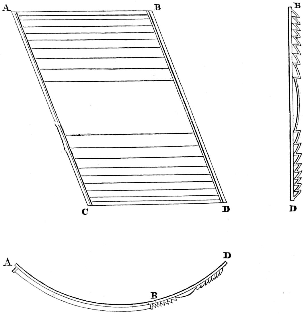
Such an apparatus is shewn in Plate XVII.; and the accompanying diagram (fig. 70) shews an elevation ABCD, a section BD, and a plan ABD, of a single pannel of this improved compound belt. AC and BD are the diagonal joints above described. Time and perseverance, and the patience and skill of Monsieur François Soleil, whom I urged to undertake the task, were at length crowned with success; and I had the satisfaction at last of seeing a fixed light apparatus, having its form truly cylindric, and its central belt in one piece, while the joints were inclined to the horizon at such an angle as to render the light perfectly equal in every azimuth.
The loss of light by reflection at the surface of the most perfect mirrors, and the perishable nature of the material composing their polish, induced me, so far back as 1835, in a Report on the Light of Inchkeith, which had just been altered to the dioptric system, to propose the substitution of totally reflecting prisms, even in lights of the first order or largest dimensions. In this attempt I was much encouraged by the singular liberality of Mr Leonor Fresnel, to whose friendship (as I have often, with much pleasure, acknowledged) I owe all that I know of dioptric Lighthouses. He not only freely communicated to me the method pursued by his distinguished brother Augustin Fresnel, in determining the forms of the zones of the small apparatus, introduced by him into the Harbour Lights of France, and his own mode of rigorously solving some of the preliminary questions involved in the computations; but put me in possession of various important suggestions, which substantially embrace the whole subject. Another friend also helped me, by pointing out certain less direct methods of determining some of the elements, which greatly abridged the labours of computation. Mr Fresnel agreed with me in anticipating a considerable increase of the light derived from the accessory part of the apparatus; but he expressed his opinion, that in order to prevent great absorption, the rings should not greatly exceed those of the small apparatus in their sectional area. This would have required about forty rings to intercept the same quantity of light acted upon by the curved mirrors; and, although the difficulties of grinding were somewhat similar to those which had already been encountered in forming the cylindric belt for the Isle of May apparatus, there were also some special difficulties attending the formation of the Catadioptric Zones. catadioptric zones, which appeared so formidable as to deter me by the expense of grinding so many zones, and led me to think of adopting flint glass. Considerable masses, of a very pure and homogeneous appearance, had been shewn to me by the late Dr Ritchie of the London University, who calculated upon the uniform and permanent success of his process; but, whatever foundation there might have been for this hope, it was removed by his death, which occurred soon afterwards, and I was forced to return to the idea of using crown glass. In order, therefore, to enable me to estimate more correctly the advantage of the zones, I procured from Messrs Cookson of Newcastle, an average specimen of crown glass, of the thickness of 40 mm. (about 1¹⁄₂ inch), which is the distance traversed by the ray between its immergence into and its emergence out of the zones of the small apparatus; and having had it carefully polished, with both faces parallel, I found, as the result of numerous trials, conducted with every precaution I could think of, that the loss of light due to the transmission through it, was somewhat less than ²⁄₇ths of the incident light. According to the experiments of Bougeur, the loss by the two refractions may be assumed at ¹⁄₂₀th; so that we could not sensibly err in concluding that the whole loss due to the transmission of the light through the zones would not much exceed ²⁄₇ths of the incident light. In the lights of the first order, the loss by reflection from the surface of the mirrors, and by the escape of light through the interstices which separate them, is not less than ²⁄₃ds of the light incident on that part of the apparatus. On the most moderate expectation, therefore, which this proportion seemed to warrant, it appeared that, without any allowance for imperfections in the figure of the zones, at least twice as much light would be transmitted through the zones as can be reflected by the mirrors. The prospect even of a part of this increase being obtained without the expenditure of more oil, seemed too important to be readily renounced, more especially when it was considered that the fixed lights, to which it chiefly applies, are necessarily much feebler than the revolving lights, as well as more numerous and more expensive. So many motives pressed me to the work, that I commenced my labours (during my leisure hours while engaged at the Skerryvore), and computed Tables of the Elements of 45 zones, whose lesser sides were 40 millimètres in length, which were printed in 1840. In 1841, in consequence of having seen at Paris specimens of purer crown glass, I printed other Tables from computations of larger zones, which I had made in 1838, but had discarded as unsuited to the inferior quality of English glass, whose absorption rendered the use of smaller dimensions of the zone imperative. In the first Table, I had adopted the form of isosceles triangles, to avoid the difficulty of grinding annular surfaces with radii of great length (which I found required to be nearly 30 feet), but in the second Table, I adopted a suggestion, conveyed to me in a letter from M. Leonor Fresnel, by giving each zone the form of an oblique triangle whose base is the chord of the circle which osculates the surface of the reflecting side of the zone. Some attempts were made by Messrs Cookson at Newcastle to execute the largest of the zones; but the forms differed so widely from the dimensions assigned in the Table, that I had begun to despair of success. About this time, I received a communication from M. Fresnel, pointing out several inaccuracies in my Tables, and more especially directing my attention to the disadvantage of choosing, for the focus of the upper series of zones, a high part of the flame, as I had done with the view of throwing all the light below the horizon, so that none might be lost. He, at the same time, informed me of the success of M. François Soleil, in executing zones for the smaller apparatus, known by the name of the Third Order; and put me in possession of the results of his computations of large zones of the First Order, suited to the greatly improved quality of the crown glass of St Gobain, with an invitation, before I should adopt his dimensions, to verify his calculations. This I willingly undertook, and computed the elements of the zones in M. Fresnel’s Table afresh, with results differing from his only in one or two instances, to an amount whose angular value does not exceed more than 2″. The Table in the Appendix contains the result of my calculations, which are verifications of those of M. Fresnel. The subject of the zones has thus been very fully weighed; and it is most satisfactory to think that complete success has attended the perseverance and ardour of M. François Soleil, who at once boldly undertook to furnish for the Skerryvore Lighthouse the first catadioptric apparatus ever constructed on so magnificent a scale. On the 23d December 1843, M. Fresnel announced, in a letter to me, the complete success which had attended a trial of the apparatus at the Royal Observatory at Paris, whereby it appeared that the illuminating effect of the cupola of zones, was to that of the seven upper tiers of mirrors of the first order, as 140 to 87. Nothing can be more beautiful than an entire apparatus for a fixed light of the first order, such as that shewn in Plates XVII. and XVIII. It consists of a central belt of refractors, forming a hollow cylinder 6 feet in diameter, and 30 inches high; below it are six triangular rings of glass, ranged in a cylindrical form, and above a crown of thirteen rings of glass, forming by their union a hollow cage, composed of polished glass, 10 feet high and 6 feet in diameter! I know no work of art more beautiful or creditable to the boldness, ardour, intelligence, and zeal of the artist.
I must now endeavour to trace the various steps by which the elements of the zones given in the appended Table have been determined; and this, I fear, I cannot do without considerable prolixity of detail. Referring to Plates XV., XVI., XVII., and XVIII., in which F shews the flame, RR, the refractors, and MRM and MRM, the spaces through which the light would escape uselessly above and below the lens, but for the corrective action of the mirrors MM, which project the rays falling on them to the horizon, I have to observe that a similar effect is obtained, but in a more perfect manner, by means of the zones ABC and A₂B₂C₂ (fig. 71, on page 271), whose action on the divergent rays of the lamp causes the rays FC, FB and FC₂, FB₂ to emerge horizontally, by refracting them at the inner surfaces BC, B₂C₂, reflecting them at AB, A₂B₂, and a second time refracting them at AC, A₂C₂.
Fig. 71.
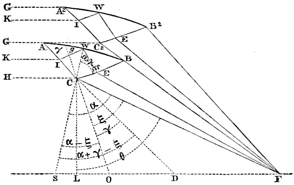
The problem proposed is, therefore, the determination of the elements and position of a triangle ABC, which, by its revolution about a vertical axis, passing through the focus of a system of annular lenses or refractors in F, would generate a ring or zone capable of transmitting in an horizontal direction by means of total reflection, the light incident upon its inner side BC from a lamp placed in the point F. The conditions of the question are based upon the well-known laws of total reflection, and require that all the rays coming from the focus F shall be so refracted at entering the surface BC, as to meet the side BA at such an angle, that instead of passing out they shall be totally reflected from it, and passing onwards to the side CA shall, after a second refraction at that surface, finally emerge from the zone in an horizontal direction. For the solution of this problem, we have given the positions of F the focus, of the apex C of the generating triangle of the zone, the length of the side BC or CA, and the refractive index of the glass. The form of the zone must then be such as to fulfil the following conditions:—
1. The extreme ray FB must suffer refraction and reflection at B, and pass to C, where being a second time refracted, it must follow the horizontal direction CH.
2. The other extreme ray FC must be refracted in C and passing to A, must at the point be reflected, and a second time reflected, so as to follow the horizontal course AG (see fig. 72, on opposite page).
These two propositions involve other two in the form of corollaries.
1. That every intermediate ray proceeding from F, and falling upon BC in any point E, between B and C, must, after refraction at the surface BC in E into the direction EW, be so reflected at W from AB into the direction WI, that being parallel to BC, it shall, after a second refraction in I, at the surface AC, emerge horizontally in the line IK.
And, 2. That the paths of the two extreme rays must therefore trace the position of the generating triangle of the zone.
To these considerations it may be added, that as the angles BCH and FCA are each of them solely due to the refraction at C, as their common cause, they must be equal to each other, and BCA being common to both, the remaining angle ACH = the remaining angle BCF.
We naturally begin by the consideration of the lowest ray FC, whose path being traced gives the direction of the two refracting sides BC and AC, leaving only the direction of the reflecting side BA to be determined. I shall not now explain the reason for neglecting entirely the consideration of the reflecting side at present, as I could not do so without anticipating what must be more fully discussed in the sequel; but I may content myself with stating, that as the positions of BC and AC depend upon the direction of the incident ray FC, and on the refractive index of the glass, this part of the investigation may be carried on apart from any interference with the reflecting side.
As we know the relation existing between the angles of incidence and refraction, we might determine the relative positions of the sides AC and BC, by means of successive corrections obtained by protraction, tracing the paths of the rays from the horizontal directions backwards through the zones to the focus. This method, however, depends entirely upon accurate protraction, and is therefore unsatisfactory as a final determination, or if employed for any other purpose than that of affording a rough approximation to the value of the angle, a knowledge of which may occasionally save trouble in the employment of more exact means of determination. I have not, however, on any occasion employed this process, as I found that a little practice enabled me to make my first estimation very near the truth. I shall therefore at once proceed to give a view of the reasoning employed in the investigation.
Fig. 72.
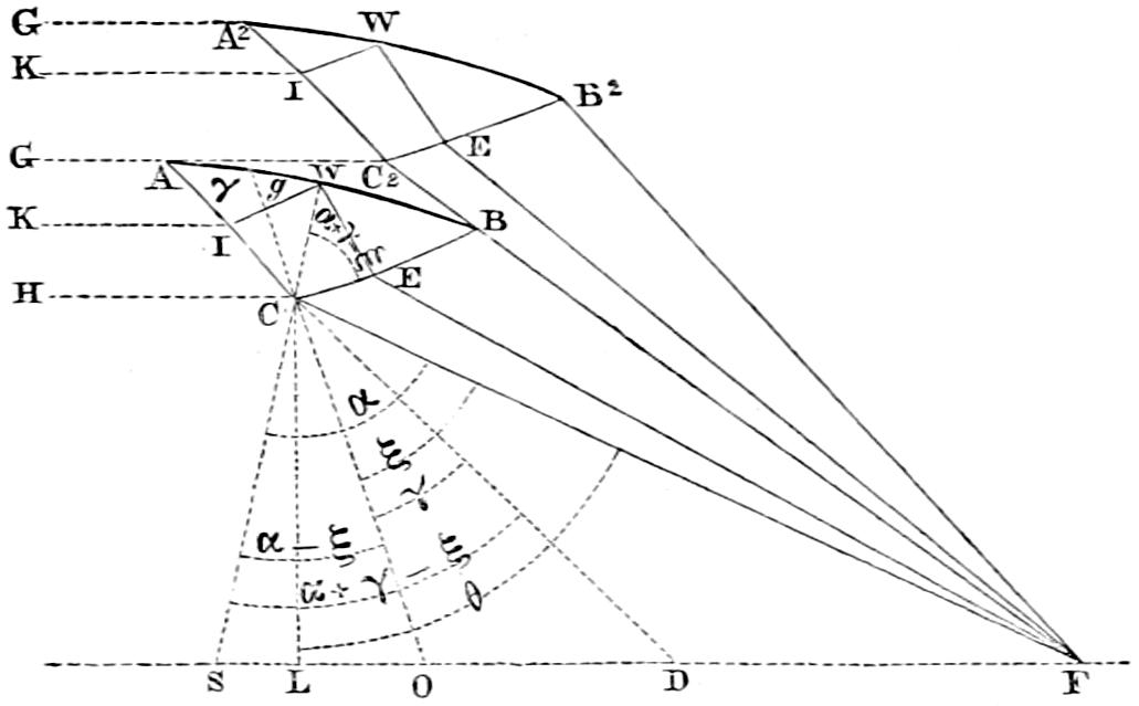
Referring to fig. 72, which shews the first and second zone of the upper series, we have
Tan LCF = FLCL;
and if we make
the known angle, SCF = α
OCF = ξ = the complement of BCF = the angle of incidence for FC.
DCΟ = γ = angle of refraction.
LCF = θ = (HCF - 90°) = (2 α - 90°)
SCD = (α + γ - ξ)
And m = the index of refraction for crown glass,
we obtain the means of determining the angles γ and ξ in two equations, which are based upon the relation between the angles of incidence and refraction, and on the interdependence of the various angles about C. These primary equations are:
sin ξ = m . sin γ and [66]γ = 2 ξ - θ (making 2 α - 90° = θ)
Eliminating γ between these two equations we obtain:
sin ξ = m . sin (2 ξ - θ)
an expression, which, after various transformations of circular functions, assumes the form
sin⁴ ξ - 1m sin θ . sin³ ξ + (1 4 m² - 1) . sin² ξ + 12 m sin θ . sin ξ + ¹⁄₄ sin² θ = 0[67]
The solution of this equation, which is of the fourth degree, is somewhat tedious; but as the root, which will satisfy the optical conditions of the question, must be the sine of an angle, and necessarily lies between zero and unity; and as the protraction, if conducted with due care in the manner already described, affords the means of at once assuming a probable value of ξ not very distant from the truth, the labour of the calculation, in this particular case, is not quite so great as might be expected. But notwithstanding all the abridgments of which the particular case admits, a considerable amount of labour is required, and a corresponding risk of error incurred, in merely introducing the numerical values into the equation preparatory to its solution; and any other method requiring less arithmetical operation, is, of course, greatly to be preferred. I therefore willingly adopted the suggestion of a friend, the benefit of whose advice I have on many occasions experienced, and made use of the following ordinary method of approximating to the root of the equation.
If the equation sin ξ - m sin (2 - θ) = 0 (see page 274) be regarded as an expression for the error, when the true value of ξ which would satisfy the equation has been introduced into its first member, we may consider any error in the value of ξ as expressed by the equation:
sin ξ - m . sin (2 ξ - θ) = ε
and differentiating this expression we have:
d ε = cos ξ . d ξ - 2 m cos (2 ξ - θ) . d ξ
= {cos ξ - 2 m cos (2 ξ - θ)} . d ξ
Then dividing by the differential coefficient we obtain
d ξ = d ε cos ξ - 2 m cos (2 ξ - θ)
But when ξ becomes ξ + d ξ, ε will also become ε + d ε; but
ε + d ε = 0
therefore d ε = -ε
hence by substitution we have
d ξ = -ε cos ξ - 2 m cos (2 ξ - θ)
d ξ = -{sin ξ - m sin (2 ξ - θ)} cos ξ - 2 m cos (2 ξ - θ)
d ξ = -sin ξ + m sin (2 ξ - θ) cos ξ - 2 m cos (2ξ - θ)
By substituting, therefore, in this last equation the known values of m and θ, and the assumed value of ξ, a correction is obtained, which being applied to ξ and the same process repeated, new corrections may be found until the value of d ξ falls within the limits of error, which may be considered safe in the particular case. I need hardly say, that where so great a body of flame is employed as in the lights of the first order, these limits are soon passed, more especially as one soon acquires by a little experience the means of guessing a value of ξ not very far from the truth. It is this method I have employed in calculating the appended tables of the zones, in which I have on all occasions, though, perhaps, with needless exactness, pushed my angular determinations to seconds.
Having in this manner determined the angles of BCF, the obtuse angle BCA of the generating triangle of the zone is easily and directly deduced by the following expression, which results from the obvious relations existing among the known angles about C; and we have (see fig. 73),
BCA = 90° + γ = 90° + 2 ξ - θ.
We next proceed to consider the form of BA, the reflecting side of the zone, which is a point of the greatest consequence, as an error in the inclination of any part of its surface is doubled in the resulting direction of the reflected rays. The conditions of the question require, that every ray EW, after reflection at the surface AB, shall, like WI, be parallel to the first ray, which is reflected in the direction BC, and after a second refraction at C, emerges horizontally in CH. But, let us trace backwards the rays as they emerge in their horizontal directions IK, and it is obvious that if BA be made a straight line, then will every ray EW meet the first refracting side BC at the same angle, and there suffering the same refraction, they will go on parallel to each other, and never meet in the focus F. This convergence to F, which is a necessary condition of the problem, may, however, be produced by a curvature of AB, such that all the rays shall have a degree of convergence before falling on BC, sufficient to cause them to be finally refracted, so as to meet in F. On this account, they will occupy less space in passing through BC, than they did in passing through AC; and thus BC will be shorter than AC by some quantity which shall give to that part of AB which is at B the amount of downward inclination required for causing the ray BF finally to converge to F; and the line joining B and A must be a curve, every point of which has its tangent inclined so as to serve the same purpose.
Fig. 73.
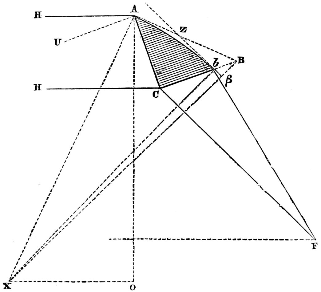
To trace tangents to this curve, is therefore the next step in the process. The direction of the first tangent AZ depends upon very simple considerations; and all that is necessary to be done is to draw a line AU (fig. 73), parallel to BC (which is the parallel to the direction of the reflected rays), and forming an angle CAU, which is, of course, equal to the inclination of the extreme rays refracted by CB at C, with rays reflected from the arc which we have yet to trace. The line AX bisecting this angle, must therefore be a normal to the reflecting surface at A, and AB drawn perpendicular to AX, is consequently a tangent to the reflecting arc.
We must next find the direction of the second tangent Z b, which must be so inclined that the ray F b will, after refraction at b, be reflected into the direction, b C; but as the rigorous determination of this is difficult, I shall describe two approximations suggested to me by M. Leonor Fresnel. The first method is based upon assuming the inclination of the ray refracted at b to the ray refracted at C as equal to:
b FCm
(in which expression, m is the refractive index of the glass); a supposition which obviously differs very little from the truth, as small arcs may be assumed as nearly equal to their sines. Now, it will be recollected, that the rays refracted at C and b, must be reflected at A and b, in a direction parallel to C b, and therefore the inclination of the reflecting surfaces, or that which should be formed by the tangents ZA and Z b, being half that of the incident rays, is, according to the assumption, equal to b FC2 m, which may be expressed by ¹⁄₃ b FC, m being equal to 1·51. But as the inclination of the two radii AX and BX is equal to the inclination of the tangents of the reflecting surfaces to which they are normals, we obtain for the excess B β of the secant of the reflecting arc over its radius the following expression:
Bβ = ¹⁄₂ AB . tan ¹⁄₃ BFC.[68]
The value of B b gives, of course, the direction of the second tangent Z b (which must be equal in length to AZ), whence we easily deduce the chord of the reflecting side A b.
The second mode proposed by M. Fresnel, and that which I found most convenient in practice, consists in forming successive hypotheses as to the length of the side BC, and tracing the path of the incident ray FB, which being refracted at B, so as to make with the normal BK an angle = BKY = y′, and finally reflected in the direction BC, must make the angle YBZ = MBC. I shall describe it as follows: In the annexed figure (fig. 75) MBZ is a tangent to the reflecting surface at B, and KBF is the angle of incidence of the ray BF before its refraction at B. If KBF = x´, and the angle of incidence of FC = ECF = x, we have BFC (which is the inclination of those rays to each other, and must be equal to the difference of their angles of incidence to the same surface) = x - x´, whence knowing x, we easily find a value of x´ corresponding to the length of BC. Then for finding the angle of refraction KBY = y´ we have:
sin y´ = sin x´m
Fig. 75.
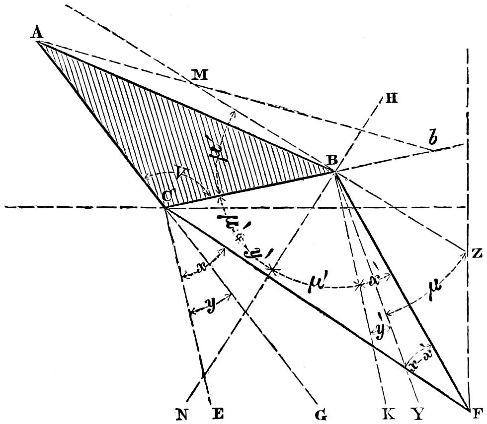
Now, if FB be refracted, so as to make with the reflecting side an angle equal to ZBY, it must (if the position of B be rightly chosen), be reflected so as to follow BC, thus making MBC = YBZ, and calling each of these angles = μ, we have the right angle NBZ made up of μ + y´ + NBK. But NBK clearly equals μ, because it is the inclination of the normals to BC and BZ, and hence y´ + 2 μ = 90°. This, therefore, forms a crucial test for the length of BC. I may only remark, that we already know the numerical value of y; and that of μ is easily found, for μ = CBA + ABM = CBA + BAM = CBA + (MAC - BAC) = CBA + ¹⁄₂ (180° - υ) - BAC. Thus knowing μ and y´, we have only to see whether
(y´ - 2 μ) - 90° = 0
We have now only to find the length of the radius AX or b X (see fig. 73, p. 277), which will describe the reflecting surface or arc AZ b, and to determine the position of its centre X. We already know the values of y′ and y, the angles of refraction of C and b, and their difference y - y′ gives us the inclination of the rays which are to be reflected (into directions parallel to C b) at b and at A. This quantity is, of course, double the inclination of tangents to the reflecting surface AZ and b Z, and of their normals AX and b X. Again, we have the chord line
A b = AC . sin AC b sin (b CA);
and, as above,
AX b = ¹⁄₂ y - y′ = φ
And AX = b X = ρ = A b . sin ¹⁄₂ (180° - φ) sin φ = ¹⁄₂ A b . cosec ¹⁄₂ φ.
And, lastly, for the co-ordinates to X, the centre of curvature for the reflecting arc, we have
OX = ρ . sin OAX
and OA = ρ . cos OAX.[69]
Fig. 76.
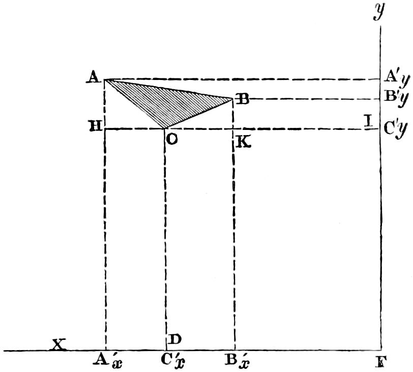
The positions of the apices A and B of the angles of the zones are also easily found in reference to the focus, and are given in the Table in the Appendix. In fig. 76 we may, in reference to the known position of C, find that of A or B, by simply adding the quantities AH, HC, and BK, to C y or C x, and by deducting CK from C y; while it is obvious that those quantities are respectively proportional to the length of the known sides AC and BC, modified by the inclination of those sides with the horizon. Hence we have AH = AC . sin ACH; HC = AC . cos ACH; BK = BC . sin BCK; and CK = BC . cos BCK.
In the process of grinding the zones, it is found convenient for the workman to give a curved form to the refracting sides BC and AC, the one being made convex and the other concave, so that both being ground to the same radius, the convergence of the rays produced by the first shall be neutralized by the divergence caused by the second. By this arrangement we have three points given in space from which, with given radii, to describe a curvilinear triangle whose revolution round the vertical axis of the system generates the zone required. Co-ordinates to those two centres of curvature for the surfaces AC and BC were determined in reference to arris A of each zone, and will be found in the Appendix. The mode of finding those co-ordinates is, of course, similar to that already given; and, the radii being assumed at 4000 millimètres, the co-ordinates are respectively proportional to the sine and cosine of the inclination of the radius at A to the vertical line, which inclination depends upon the relations of known angles around A and C.
The section ABC (fig. 71, p. 271) of the first zone being thus determined, we proceed by fixing the point C₂ of the second zone, which is at the intersection of the horizon GAG₂ with the ray FBC₂ passing through B. This arrangement prevents any loss of light between the adjacent zones. The calculation of the elements of the second and of every following zone, is precisely similar to that of the first.
The mode of grinding the zones I shall not notice here; but shall refer the more curious reader to the Appendix, in which I have given the details of the process followed by M. Theodore Letourneau, who now manufactures the apparatus for the Northern Lights Board, in the room of M. François Soleil, who is engaged at St Petersburg in the same work. I accordingly proceed to consider what mode should be followed in Testing of Zones. testing the accuracy of the zones. For this purpose, various expedients suggested themselves, such as the application of gauges in the form of a radius, having at one end a plate with a triangular space cut through it, equal and similar to the cross section of the zone. The horizontal motion of this arm would, of course, detect the inaccuracies of the successive sections of the inclosed zone. The application of such a gauge, however, seemed difficult, and in order to test the form of the zones, I satisfied myself with using callipers (similar to the sliding rules used by shoemakers) for measuring the length of the sides of the zone, and a goniometer for the angles, which is represented in the figure (fig. 77), in which ABC represents the prism, with one angle inclosed between the arms AC and AB, moveable round a centre O, and RR the graduated limb. This instrument is inconvenient and defective, as the convexity of the sides AB and BC of the zone requires some skill in getting the arms to be tangents to them.
Fig. 77.
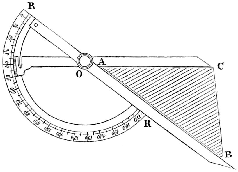
Fig. 78.
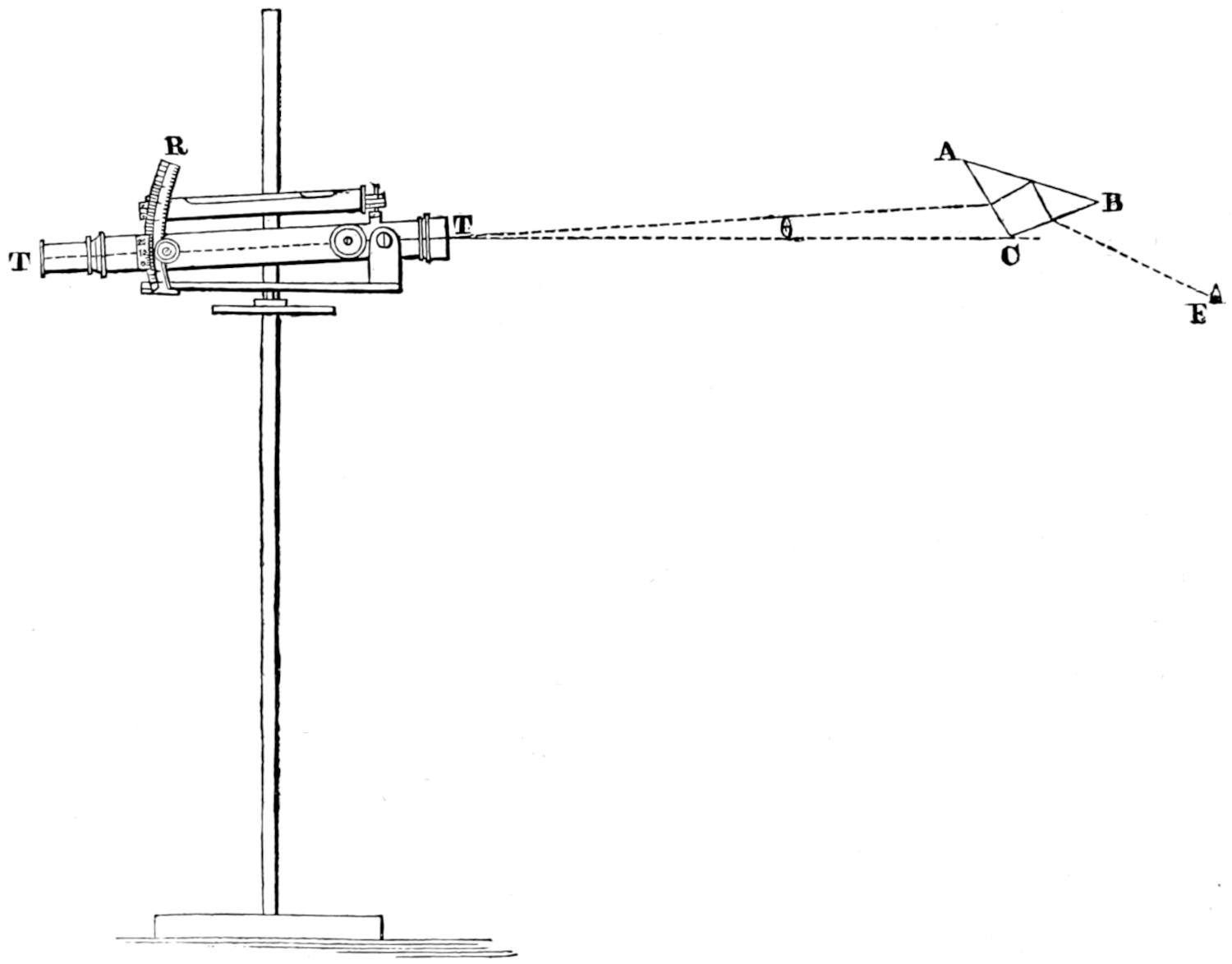
A practical test, however, yet remained to be made of the zones when fixed in the brass frames (shewn at Plate XVIII.), and assembled around the common focus of the system, by measuring the final inaccuracy in the path of the rays emergent from them. I have successfully used the following mode. Having mounted the frames containing the zones on a carriage revolving round a small flame placed truly in the common focus, I carefully marked with a piece of soap the centre of the emergent surface of each zone; and having attached to a vertical rod of metal a telescope, provided with a spirit-level and cross-hairs (for cutting the centre of the image of the flame reflected through the zone) in such a manner as to be capable of sliding on the rod, I observed the cutting of the centre of the flame by the cross-hairs. In the case of any aberration from a normal emergence of the central ray, I had thus the means of at once determining its amount and direction. The telescope was moved up or down, and its vertical inclination was varied until the axis of the instrument coincided with the direction of the ray emergent from the centre of each zone, which was made to circulate round the flame, the observer noting any change in the position of the reflected image of the flame, and causing an attendant to mark the zones in which the change occurred, that they might again be subjected to separate examination of the same kind, by adjusting the telescope to the error of each. The vertical inclination of the telescope and the consequent aberration of the ray, was then measured by a graduated arc, with an adjusting spirit-level, moved by a rack and pinion. The accompanying figure (fig. 78) shews the arrangement just described. E is the small flame in the focus; ABC is the zone; TT is the telescope; and R a graduated limb, on which is read the angular deviation θ of the axis of the telescope from the horizon. In the figure, the ray emergent from the centre of AC is shewn dipping below the true level, to which the line TC is supposed to be parallel. I have succeeded by this method in detecting the inaccurate position of some of the zones in the frame; and the error has been reduced by carefully resetting them, so as to diminish considerably the error of a great proportion of the emergent rays. Another mode, and that which, owing to its convenience, was chiefly employed in preference to that just described, was to measure the vertical inclination (given in the Table in the Appendix), of each surface of the zone, and more especially the reflecting surface, by means of the instrument, shewn in figures 79 and 80, after the zones were fixed in their place. The figure (No. 79) shews the mode of gauging the reflecting side AB of a zone of the upper series; and the second (No. 80) shews the position of the instrument in gauging the reflecting side AB of a zone of the under series. In those figures, L is a spirit-level; R, a graduated limb for reading the angular deviation from the true inclination of the tangents to each surface; and SS are studs which rest on the convex surfaces AB and BC of the zones, so as to make the ruler parallel to the tangents of those sides. I have only to add, that I have restricted the error, in the position of the reflecting side of the zones, to 50′ as an extreme limit; and I have invariably endeavoured, in altering the position of the zone in the frame, to throw any error on the side of safety, by causing the rays to dip below the horizon, rather than to rise above it.[70]
Fig. 79.
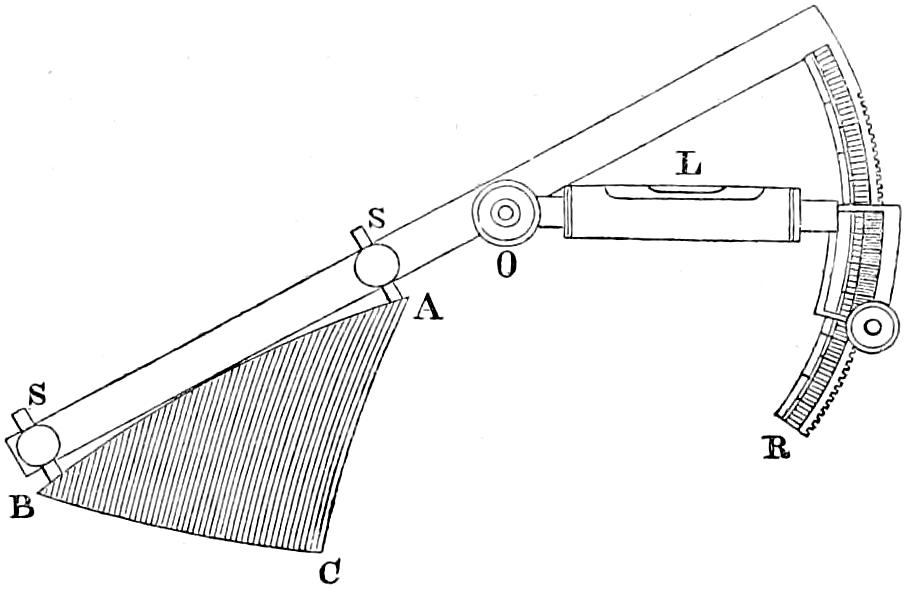
Fig. 80.
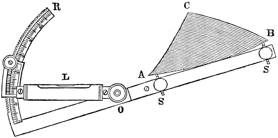
Framing of Zones. The mode of framing the greater zones is shewn in Plate XVIII. and is nearly the same as that used for the Small Harbour Light apparatus of the fourth order (Plate XIX.). The chief difference consists in the diagonal framing, which I adopted for supporting the cupola of 13 zones, which, from its great weight, could not be safely made to rest on the dioptric belt below. That frame is seen in Plates XVII. and XVIII. and is in accordance with the mode of jointing the refractors already described. This system has now been rendered still more complete by the adoption of lanterns composed of diagonal framework, afterwards described and shewn at Plate XXVI.
Mechanical Lamp. We have next to consider the great Lamp, to the proper distribution of whose light, the whole of the apparatus, above described, is applied. Fresnel immediately perceived the necessity of combining with the dioptric instruments which he had invented, a burner capable of producing a large volume of flame; and the rapidity with which he matured his notions on this subject and at once produced an instrument admirably adapted for the end he had in view, affords one of the many proofs of that happy union of practical with theoretical talent, for which he was so distinguished. Fresnel himself has modestly attributed much of the merit of the invention of this Lamp to M. Arago; but that gentleman, with great candour, gives the whole credit to his deceased friend, in a notice regarding lighthouses, which appeared in the Annuaire du Bureau des Longitudes of 1831. The lamp has four concentric burners, which are defended from the action of the excessive heat, produced by their united flames, by means of a superabundant supply of oil, which is thrown up from a cistern below by a clockwork movement and constantly overflows the wicks, as in the mechanical lamp of Carcel. A very tall chimney is found to be necessary, in order to supply fresh currents of air to each wick with sufficient rapidity to support the combustion. The carbonisation of the wicks, however, is by no means so rapid as might be expected, and it is even found that after they have suffered a good deal, the flame is not sensibly diminished, as the great heat evolved from the mass of flame, promotes the rising of the oil in the cotton. I have seen the large lamp at the Tour de Corduan burn for seven hours without being snuffed or even having the wicks raised; and, in the Scotch Lighthouses, it has often, with Colza oil, maintained, untouched, a full flame for no less a period than seventeen hours.
Fig. 82.
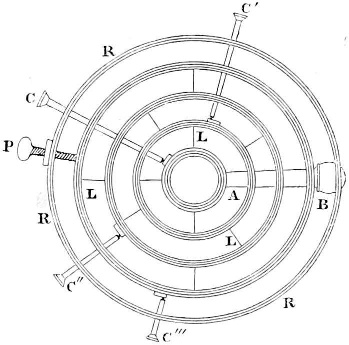
Fig. 83.
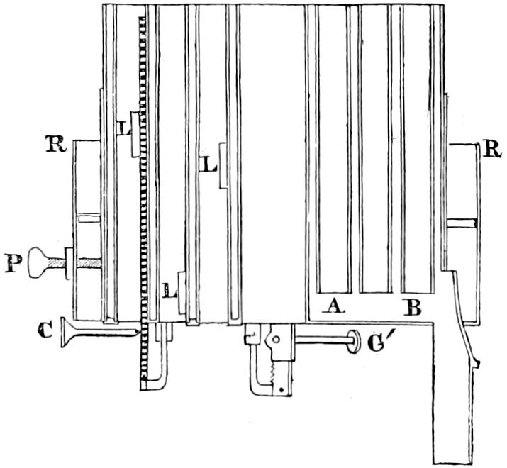
Fig. 84.
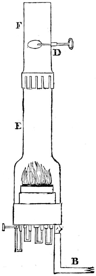
The annexed diagrams will give a perfect idea of the nature of the concentric burner. The first (fig. 82) shews a plan of a burner of four concentric wicks. The intervals which separate the wicks from each other and allow the currents of air to pass, diminish a little in width as they recede from the centre. The next (fig. 83) shews a section of this burner. C, C′, C″, C‴ are the rack-handles for raising or depressing each wick; AB is the horizontal duct which leads the oil to the four wicks; L, L, L, are small plates of tin by which the burners are soldered to each other, and which are so placed as not to hinder the free passage of the air; P is a clamping screw, which keeps at its proper level the gallery R, R, which carries the chimney. The last figure (No. 84) shews the burner with its glass chimney and damper. E is the glass chimney; F is a sheet-iron cylinder, which serves to give it a greater length, and has a small damper D, capable of being turned by a handle, for regulating the currents of air; and B is the pipe which supplies the oil to the wicks. The only risk in using this lamp arises from the liability to occasional derangement of its leathern valves that force the oil by means of clockwork; and several of the lights on the French coast, and more especially the Corduan, have been extinguished by the failure of the lamp for a few minutes, an accident which has never happened, and scarcely can occur with the fountain lamps which illuminate the reflectors. To prevent the occurrence of such accidents, and to render their consequences less serious, various precautions have been resorted to. Amongst others, an alarum is attached to the lamp, consisting of a small cup pierced in the bottom, which receives part of the overflowing oil from the wicks, and is capable, when full, of balancing a weight placed at the opposite end of a lever. The moment the machinery stops, the cup ceases to receive the supply of oil, and, the remainder running out at the bottom, the equilibrium of the lever is destroyed, so that it falls and disengages a spring which rings a bell sufficiently loud to waken the keeper should he chance to be asleep. It may justly be questioned whether this alarum would not prove a temptation to the keepers to relax in their watchfulness and fall asleep; and I have, in all the lamps of the dioptric lights on the Scotch coast, adopted the converse mode of causing the bell to cease when the clockwork stops. There is another precaution of more importance, which consists of having always at hand in the light-room a spare lamp, trimmed and adjusted to the height for the focus, which may be substituted for the other in case of accident. It ought to be noticed, however, that it takes about twenty minutes from the time of applying the light to the wicks to bring the flame to its full strength, which, in order to produce its best effect, should stand at the height of nearly four inches (10cm.). The inconveniences attending this lamp have led to several attempts to improve it; and, amongst others, M. Delaveleye has proposed to substitute a pump having a metallic piston, in place of the leathern valves, which require constant care, and must be frequently renewed. A lamp was constructed in this manner by M. Lepaute, and tried at Corduan; but was afterwards discontinued until some further improvements could be made upon it. It has lately been much improved by M. Wagner, an ingenious artist whom M. Fresnel employed to carry some of his improvements into effect. In the dioptric lights on the Scotch coast, a common lamp, with a large wick, is kept constantly ready for lighting; and, in the event of the sudden extinction of the mechanical lamp by the failure of the valves, it is only necessary to unscrew and remove its burner, and put the reserve-lamp in its place. The height of this lamp is so arranged, that its flame is in the focus of the lenses, when the lamp is placed on the ring which supports the burner of the mechanical lamp; and as its flame, though not very brilliant, has a considerable volume, it will answer the purpose of maintaining the light in a tolerably efficient state for a short time, until the light-keepers have time to repair the valves of the mechanical lamp. Only three occasions for the use of this reserve-lamp have yet occurred.
Height of the flame of the Mechanical Lamp.The most advantageous heights for the flames in dioptric lights are as follows:—
Inches.
1st Order, 10 to 11 centimètres = 3·94 to 4·33
2d Order, 8 to 9 ...... = 3·15 to 3·54
3d Order, 7 to 8 ...... = 2·76 to 3·15
Those heights of flame can be obtained only by a careful adjustment of the heights of the wicks and the relative levels of the shoulder of the glass-chimney and the burner, together with a due proportion for the area of the opening of the iron-damper which surmounts it. The wicks must be gradually raised during the first hours of burning to the level of 7 millimètres (0·27 inch) above the burner, a height which they may only very rarely and but slightly exceed. By raising the shoulder of the glass-chimney the volume of the flame is increased; but, after a certain height is exceeded, the flame, on the other hand, becomes reddish, and its brilliancy is diminished. The height of the flame is decreased, and it becomes whiter by lowering the chimney. The chimney is lowered or raised by simply turning to the right or to the left the cylindric glass-holder in which it rests (see Plate XXV.). In regulating the flame, however, recourse is most frequently had to the use of the damper, by enlarging the opening of which the flame falls and becomes whiter and purer; while by diminishing its aperture, the contrary effect is produced. The area of the opening depends on the inclination of a circular disc capable of turning, vertically through a quadrant, on a slender axle of wire, which is commanded by the light-keeper by means of a fine cord which hangs from it to the table below. When the disc (see fig. 84, p. 287) is in a horizontal plane the chimney is shut, when in a vertical plane it is open; and each intermediate inclination increases or decreases the aperture.
I need scarcely add, that in order to produce the proper effect of a system of lenses or refractors, the vertical axis of the flame should Position of flame in reference to focus of apparatus. coincide with their common axis; and it is further necessary, in order to bring the best portion of the flame into a suitable position with reference to the apparatus, that the top of the burner should be quite level, and should stand below the plane of the focus in the following proportions, viz.:—
For 1st order, 28 millimètres = 1·10 inches.
... 2d order, 26 ... = 1·02 ...
... 3d order, 24 ... = 0·95 ...
Fig. 85.
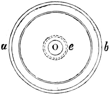
For the purpose of placing the lamp in the centre of the apparatus, a plumbet with a sharp point suspended in the axis of the apparatus, is used to indicate, by its apex, the place for the centre of the burner. The lamp is then raised or lowered as required by means of four adjusting screws Q at the bottom of its pedestal (Plate XX.); and the top of the burner is made horizontal by a spirit-level, the most convenient form of which is that of the spherical segment, which acts in every azimuth. Its application to this purpose is due, I believe, to M. Letourneau, the successor of M. François in the construction of dioptric apparatus at Paris. This level is shewn in the annexed figure (fig. 85), in which a b is the brass frame containing the level, and O the air-bubble; and e shews circles of equal altitudes engraved on the glass. After the first application of this level, the adjustment of the burner as to its central position is carefully repeated by means of a centre gauge (shewn at fig. 90, p. 295), with reference to the vertex of each lens, or to many points on the internal surface of the refractors; and being found correct, the level is again applied to the top of the burner, to detect any deviation from horizontality that may have occurred during the process of adjusting it to the axis.