PART SECOND. NOTES ON THE ILLUMINATION OF LIGHTHOUSES, WITH SHORT NOTICES OF THEIR EARLY HISTORY.
Reading edition
Early History. The early history of Lighthouses is very uncertain; and some ingenious antiquaries, finding the want of authentic records, have been anxious to supply the deficiency by conjectures based upon casual and obscure allusions in ancient writers, and by vague hypotheses drawn from the heathen mythology. Some writers have gone so far as to imagine, that the Cyclopes were the keepers of lighthouses; whilst others have actually maintained that Cyclops was intended, by a bold prosopopœia, to represent a lighthouse itself.[24] A notion so fanciful deserves little consideration; and accords very ill with that mythology of which it is intended to be an exposition, as seems sufficiently plain from a passage in the ninth Odyssey, where Homer (who flourished about 907 B. C.), after describing the darkness of the night, informs us that the fleet of Ulysses actually struck the shore of the Cyclopean island, before it could be seen.[25]
Nor does there appear any better reason for supposing, that under the history of Tithonus, Chiron, or any other personage of antiquity, the idea of a lighthouse was conveyed; for such suppositions, however reconcileable they may appear with some parts of mythology, involve obvious inconsistencies with others. It seems, indeed, most improbable, that, in those early times, when navigation was so little practised, the advantages of beacon lights were so generally known and acknowledged as to render them the objects of mythological allegory.
It must not, however, be imagined, that ancient writings are entirely destitute of allusions to the subject of Beacon Lights for the guidance of the Mariner. The venerable poet, already noticed, in speaking of the shield of Achilles, has beautifully described the flash of a beacon-light in some solitary place, as seen by seamen leaving their friends, in those lines, which contain ample proof of the existence of such a provision for the safety of the mariner in Homer’s time:—
Ὣς δ’ ὅταν ἐκ πόντοιο σέλας ναύτῃσι φανείη Καιομένοιο πυρὸς, τὸ δὲ καίεται ὑψόθ’ ὄρεσφι, Σταθμῷ ἐν οἰοπόλῳ· τοὺς δ’ οὐκ ἐθέλοντας ἄελλαι Πόντον ἐπ’ ἰχθυόεντα φίλων ἀπάνευθε φέρουσιν.
Il., xix., 375.
In the Holy Scriptures the word Beacon occurs but once, and that in Prophecies of Isaiah (xxx. 17.), who lived above 200 years later than Homer; but it is obvious that the original term, which the Septuagint translate by the word ἱστος, merely imports a flagstaff or perch and does not at all imply the knowledge of beacon-lights among the Hebrews, who were not a maritime people.
Colossus of Rhodes. About 300 years before the Christian era, Chares, the disciple of Lysippus, constructed the celebrated brazen statue, called the Colossus of Rhodes. It was of such dimensions as to allow vessels to sail into the harbour between its legs, which spanned the entrance. There is considerable probability in the idea that this figure served the purposes of a lighthouse; but there is no passage in any ancient writer, where this use of the Colossus is expressly mentioned. Many inconsistencies occur in the account of this fabric by early writers, who, in describing the distant objects which could be seen from it, appear to have forgotten the height which they assign to the figure. It was partly demolished by an earthquake, about eighty years after its completion; and so late as the year 672 of our era, the brass of which it was composed was sold by the Saracens to a Jewish merchant of Edessa, for a sum, it is said, equal to L.36,000.
Pharos of Alexandria. Little is known with certainty regarding the Pharos of Alexandria, which was regarded by the ancients as one of the seven wonders of the world. It was built in the reign of Ptolemy Philadelphus, about 300 years before the Christian era; and Strabo relates that Sostratus, a friend of the royal family, was the architect. He describes it as built in a wonderful manner in many stories of white stone, on a rock forming the promontory of the island Pharos (whence the Tower derived its name), and says that the building bore the inscription—“Sostratus of Cnidos, the son of Dexiphanes, to the Gods, the Saviours, for the benefit of seamen.” He concludes his brief notice of it by describing the neighbouring shores as low and encumbered with shoals and snares, and as calling for the establishment of a lofty and bright beacon, a sign to guide sailors arriving from the ocean into the entrance to the haven.[26]
The accounts which have come down to us of the dimensions of this remarkable edifice are exceedingly various; and the statements of the distance at which it could be seen are clearly fabulous. That of Josephus (who likens it to the second of Herod’s three Towers at Jerusalem, called Phasael, in honour of his brother) is the least removed from probability; yet even he informs us, that the fire which burnt on the top to enable seamen to anchor in sight of it, before coming near the shore, and so to avoid the difficulty of the navigation by night, was visible at a distance equal to about thirty-four English miles. Such a range for a lighthouse on the low shores of Egypt, would require a tower about 550 feet in height![27] Ammianus Marcellinus[28] and Pliny[29] are both very circumstantial in their notices of the Pharos as a beacon-light to guide seamen in approaching the coast of Egypt and port of Alexandria. The latter adds the interesting fact, that the cost of the Tower was reckoned at a sum equal to about L.390,000 of our money;[30] and both of them agree in stating that a light was shewn from it at night. Ammianus Marcellinus differs from all the other writers, in attributing the erection of the Tower to Queen Cleopatra. Pliny mentions in passing, that there were also lighthouses at Ostia and Ravenna.
If the reports of some writers are to be believed, this Tower must have far exceeded in size the great Pyramid itself; but the fact that a building of comparatively so late a date should have so completely disappeared, whilst the Pyramid remains almost unchanged, is a sufficient reason for rejecting, as erroneous, the dimensions which have been assigned by most writers to the Pharos of Alexandria. Some have pretended that large mirrors were employed to direct the rays of the beacon-light on its top, in the most advantageous direction; but, in so far as I know, there is no definite evidence in favour of this supposition. Others, with greater probability, have imagined that this celebrated beacon was known to mariners, simply by the uncertain and rude light afforded by a common fire. In speaking of the Pharos, the poet Lucian, on most occasions sufficiently fond of the marvellous, takes no notice of the gigantic mirrors which it is said to have contained. He thus speaks of this celebrated lighthouse as having indicated to Julius Cæsar his approach to the Pharos of Egypt on the seventh night after he sailed from Troy:
Septima nox, Zephyro nunquam laxante rudentes, Ostendit Phariis Ægyptia littora flammis. Sed prius orta dies nocturna lampada texit, Quam tutas intraret aquas.
Pharsal., ix., 1004.
It is true that, by using the word “lampada,” which can only with propriety be applied to a more perfect mode of illumination than an open fire, he appears to indicate that the “flammis” of which he speaks, were not so produced. The word lampada may however, be used metaphorically; and flammis would, in this case, not improperly describe the irregular appearance of a common fire.
Perhaps, also, the opinion that some kind of lamp was used in the Pharos, may seem to receive countenance from the remarkable words of Pliny, in the passage above cited—“Periculum in continuatione ignium, ne sidus existimetur, quoniam è longinquo similis flammarum aspectus est.” The fear he expresses lest the light viewed from a distance should be mistaken for a star, could hardly be applicable to the diffuse, oscillating, lambent light derived from an open fire, and certainly gives some reason for imagining that, even at that remote time, the art of illuminating lighthouses was better understood than in the early part of the present century.
Before leaving the subject of the Pharos of Alexandria, I wish to vindicate the memory of its architect Sostratus from the calumny of Lucian, who, in his Treatise on the art of writing history, with his usual acrimony, accuses the builder of the Pharos of a fraud, in cutting his own name on the solid walls of the Tower, and covering the inscription with plaster, on which he carved the name of his royal master Ptolemy.[31] Against this assertion I would oppose the testimony of Strabo, who calls Sostratus the “friend of the Kings” (see the quotation at the foot of page 183), and the direct evidence of Pliny, who, in the passage above cited, expressly states, as a proof of Ptolemy’s magnanimity, his giving the architect liberty to inscribe his own name on the Tower. The only other notices of the Pharos which I have been able to find in ancient writers are from Cæsar’s Commentaries, Valerius Flaccus, and Pomponius Mela.[32] At Alexandria, there is a modern lighthouse called the Pharos, which is maintained by the Pacha of Egypt.
Coruña Tower Mr Moore, in his History of Ireland, vol. i., p. 16, speaks of the Tower of Coruña, which he says is mentioned in the traditionary history of that country, as a lighthouse erected for the use of the Irish in their frequent early intercourse with Spain. In confirmation of this opinion, he cites a somewhat obscure passage from Æthicus, the cosmographer. This in all probability is the tower which Humboldt mentions in his Narrative under the name of the Iron Tower, which was built as a lighthouse by Caius Saevius Lupus, an architect of the city of Aqua Flavia, the modern Chaves.[33] A Lighthouse has lately been established on this headland, for which Dioptric apparatus was supplied from the workshop of M. Letourneau of Paris.
There is also a record in Strabo of a magnificent lighthouse of stone at Lighthouse at the mouth of the Guadalquivir. Capio, or Apio, near the Harbour of Menestheus (the modern Mesa Asta, or Puerto de Sta. Maria), which he describes as built on a rock nearly surrounded by the sea, as a guide for the shallows at the mouth of the Guadalquivir, in terms almost identical with those used by him in speaking of the Pharos of Alexandria. I am not aware of any other notice of this great work, for such it seems to have been, to have deserved the praises of Strabo.[34]
Ancient Phari in Britain. In Camden’s Britannia, a passing notice is taken of the ruins called Cæsar’s Altar, at Dover, and of the Tour d’Ordre, at Boulogne, on the opposite coast; both of which are conjectured to have been ancient lighthouses. Pennant describes the remains of a Roman Pharos near Holywell, but cites no authorities for his opinion as to its use. There were likewise remains of a similar structure at Flamborough-head. A very meagre and unintelligible account is also given of a lighthouse at St Edmund’s Chapel, on the coast of Norfolk, in Gough’s additions to Camden, by which it might seem that the lighthouse was erected in 1272.[35]
Such seems to be the sum of our knowledge of the ancient history of lighthouses, which, it must be admitted, is neither accurate nor extensive. Our information regarding modern lighthouses is of course more minute in its details and more worthy of credit. The greater part of it is drawn from authentic sources; and much of what is afterwards stated is the result of my own observation, during my visits to the most important lighthouses of Europe.
The first lighthouse of modern days that merits attention, is the Tour de Corduan. Tour de Corduan, which, in point of architectural grandeur, is unquestionably the noblest edifice of the kind in the world. It is situated on an extensive reef at the mouth of the river Garonne, and serves as a guide to the shipping of Bordeaux and the Languedoc Canal, and indeed of all that part of the Bay of Biscay. It was founded in the year 1584, but was not completed till 1610, under Henri IV. It is minutely described in Belidor’s Architecture Hydraulique. The building is 197 feet in height, and consists of a pile of masonry, forming successive galleries, enriched with pilasters and friezes, and rising above each other with gradually diminished diameters. Those galleries are surmounted by a conical tower, which terminates in the lantern. Round the base is a wall of circumvallation, 134 feet in diameter, in which the light-keepers’ apartments are formed, somewhat in the style of casemates. This wall is an outwork of defence, and receives the chief shock of the waves. The tower itself contains a chapel, and various apartments; and the ascent is by a spacious staircase. The first light exhibited in the Tour de Corduan was obtained by burning billets of oak-wood, in a chauffer at the top of the tower; and the use of coal instead of wood, was the first improvement which the light received. A rude reflector, in the form of an inverted cone, was afterwards added, to prevent the loss of light which escaped upwards. About the year 1780, M. Lenoir was employed to substitute paraboloïdal reflectors and lamps; and in 1822, the light received its last improvement, by the introduction of the dioptric instruments of Augustin Fresnel, the celebrated French Academician.
Eddystone. The history of the famous Lighthouse on the Eddystone Rocks is well known to the general reader, from the narrative of Smeaton the Engineer. Those Rocks are 9¹⁄₂ miles from the Ram-Head, on the coast of Cornwall; and from the small extent of the surface of the chief Rock and its exposed situation, the construction of the Lighthouse was a work of very great difficulty. The first erection was of timber, designed by Mr Winstanley; and was commenced in 1696. The light was exhibited in November 1698. It was soon found, however, that the sea rose upon that tower to a much greater height than had been anticipated; so much so, it is said, as to “bury under the water” the lantern, which was sixty feet above the Rock; and the Engineer was therefore afterwards under the necessity of enlarging the Tower, and carrying it to the height of 120 feet. In November 1703, some considerable repairs were required, and Mr Winstanley, accompanied by his workmen, went to the Lighthouse to attend to their execution; but the storm of the 26th of that month, carried away the whole erection, when the Engineer and all his assistants unhappily perished!
The want of a light on the Eddystone, soon led to a fatal accident; for not long after the destruction of Mr Winstanley’s lighthouse, the Winchilsea man-of-war was wrecked on the Eddystone Rocks, and most of her crew were lost. Three years, however, elapsed, after this melancholy proof of the necessity for a light, before the Trinity-House of London could obtain a new Act of Parliament, to extend their powers; and it was not till the month of July 1706, that the construction of a new lighthouse was begun under the direction of Mr John Rudyerd of London. On the 28th of July 1708, the new light was first shewn, and it continued to be regularly exhibited till the year 1755, when the whole fabric was destroyed by accidental fire, after it had stood forty-seven years. But for this circumstance, it is impossible to tell how long the lighthouse might, with occasional repair, have lasted, as Mr Rudyerd seems to have executed his task with much judgment, carefully rejecting all architectural decoration, as unsuitable for such a situation, and directing his attention to the formation of a tower which should offer the least resistance to the waves. The height of the tower, which was of a conical form and constructed of timber, was 92 feet, including the lantern; and the diameter at the base, which was a little above the level of high water, was 23 feet.
The advantages of a light on the Eddystone having been so long known and acknowledged by seamen, no time was permitted to elapse before active measures were taken for its restoration; and Smeaton, to whom application was made for advice on the subject, recommended the exclusive use of stone as the material, which, both from its weight and other qualities, he considered most suitable for the situation. On the 5th of April 1756, Smeaton first landed on the Rock and made arrangements for erecting a Lighthouse of stone and preparing the foundations, by cutting the surface of the rock into regular horizontal benches, into which the stones were carefully dovetailed or notched. The first stone was laid on 12th June 1757 and the last on the 24th of August 1759. The Tower measures 68 feet in height and 26 feet in diameter at the level of the first entire course; and the diameter under the cornice is 15 feet. The first 12 feet of the Tower form a solid mass of masonry; and the stones of which it is composed are united by means of stone joggles, dovetailed joints, and oaken treenails. It is remarkable that Smeaton should have adopted an arched form for the floors of his building, instead of employing the floors as tie-walls formed of dovetailed stones. To counteract the injurious tendency of the outward thrust of those arched floors, he had recourse to the ingenious expedient of laying, in circular trenches or grooves cut in the stones which form the outside casing, tie-belts of chain, which were heated before being set in the grooves by means of an application of hot lead and became tight in cooling, after they were fixed in the wall. The light was exhibited on the 16th October 1759; but such was the state of lighthouse apparatus in Britain at that period, that a feeble light from tallow candles was all that decorated this noble structure. In 1807, when the property of this lighthouse again came into the hands of the Trinity-House, at the expiry of a long lease, Argand burners, and paraboloïdal reflectors of silvered copper, were substituted for the chandelier of candles.
Bell Rock. The dangerous reef called the Inch Cape, or Bell Rock, so long a terror to mariners, was well known to the earliest navigators of Scotland. Its dangers were so generally acknowledged, that the Abbots of Aberbrothwick, from which the Rock is distant about twelve miles, caused a float to be fixed upon the Rock with a bell attached to it, which being swung by the motion of the waves, served by its tolling to warn the mariner of his approach to the reef. From this circumstance, which formed the groundwork of Southey’s striking ballad of Sir Ralph the Rover, the Rock is said to have derived its name. Amongst the many losses which occurred on the Bell Rock in modern times, one of the most remarkable is that of the York, seventy-four, with all her crew, part of the wreck having been afterwards found on the Rock and part having come ashore on the neighbouring coast. During the survey of the Rock also, several instances were discovered of the extent of loss which this reef had occasioned; and many articles of ships’ furnishings were picked up on it, as well as various coins, a bayonet, a silver shoe-buckle, and many other small objects. Impressed with the great importance of some guide for the Bell Rock, Captain Brodie, R.N., set a small subscription on foot and erected a beacon of spars on the Rock, which, however, was soon destroyed by the sea. He afterwards constructed a second beacon, which soon shared the same fate. It was not, therefore, until 1802, when the Commissioners of Northern Lights brought a bill into Parliament for power to erect a lighthouse on it, that any efficient measures were contemplated for the protection of seamen from this Rock, which, being covered at every spring-tide to the depth of from twelve to sixteen feet, and lying right in the fairway to the Friths of Forth and Tay, had been the occasion of much loss both of property and life. In 1806, the bill passed into a law; and various ingenious plans were suggested for overcoming the difficulties which were apprehended, in erecting a lighthouse on a rock twelve miles from land, and covered to the depth of twelve feet by the tide. But the suggestion of Mr Robert Stevenson, the Engineer to the Lighthouse Board, after being submitted to the late Mr Rennie, was at length adopted; and it was determined to construct a tower of masonry, on the principle of the Eddystone. On the 17th of August 1807, Mr Stevenson accordingly landed with his workmen and commenced the work by preparing the Rock to receive the supports of a temporary pyramid of timber, on which a barrack-house for the reception of the workmen (similar to that which has already been described in a preceding part of this volume) was to be placed; and during this operation, much hazard was often incurred in transporting the men from the Rock, which was only dry for a few hours at spring-tides, to the vessel which lay moored off it. The lowest floor of this temporary erection, in which the mortar for the building was prepared, was often broken up and removed by the force of the sea. The foundation for the tower having been excavated, the first stone was laid on the 10th July 1808, at the depth of sixteen feet below the high water of spring-tides; and at the end of the second season, the building was five feet six inches above the lowest part of the foundation. The third season’s operations terminated by finishing the solid part of the structure, which is thirty feet in height; and the whole of the masonry was completed in October 1810. The light was first exhibited to the public on the night of the 1st of February 1811. The difficulties and hazards of this work were chiefly caused by the short time during which the Rock was accessible between the ebbing and flowing tides; and amongst the many eventful incidents which render the history of this work interesting, was the narrow escape which the Engineer and thirty-one persons made from being drowned, by the rising of the tide upon the Rock, before a boat came to their assistance, at a time when the attending vessel had broken adrift. This circumstance occurred before the Barrack-house was erected, and is narrated by Mr Stevenson, in his Account of the work, published at the expense of the Lighthouse Board in 1824, to which I would refer for more minute information on the subject of this work and the other lighthouses on the coast of Scotland.
The Bell Rock Tower is 100 feet in height, 42 feet in diameter at the base, and 15 at the top. The door is 30 feet from the base and the ascent is by a massive copper ladder. The apartments, including the light-room, are six in number. The light is a revolving red and white light; and is produced by the revolution of a frame containing sixteen Argand lamps, placed in the foci of paraboloïdal mirrors, arranged on a quadrangular frame, whose alternate faces have shades of red glass placed before the reflectors, so that a red and white light is shewn successively. The machinery, which causes the revolution of the frame containing the lamps, is also applied to tolling two large bells, to give warning to the mariner of his approach to the Rock in foggy weather. The erection of the Bell Rock Lighthouse cost L.61,331 : 9 : 2.
Carlingford. The most remarkable Lighthouse on the coast of Ireland is that of Carlingford, near Cranfield Point, at the entrance of Carlingford Lough. It was built according to the design of Mr George Halpin, the Inspector of the Irish Lights; and was a work of an arduous nature, being founded 12 feet below the level of high-water, on the Hawlbowling Rock, which lies about two miles off Cranfield Point. The figure of the Tower is that of a frustum of a cone, 111 feet in height, and 48 in diameter at the base. The light, which is fixed, is from oil burned in Argand lamps, placed in the foci of paraboloïdal mirrors. It was first exhibited on the night of December 20, 1830.
There are various other Lighthouses, which, in themselves, are sufficiently deserving of a separate notice, were it not that they have more or less something in common with those already described, which are unquestionably the most remarkable edifices of the kind. The first design for an Iron Lighthouses. Iron Lighthouse, is that by my Father for the Bell Rock, in the year 1800. The invention of Mr Mitchell of Belfast, for applying the principle of the screw to the erection of Lighthouses on soft foundations, deserves a longer notice than is consistent with the nature of these notes. It must therefore be sufficient to say, that the principal Lighthouses on this plan (those of the Maplin, Fleetwood, and Belfast Lough) consist of piles or of hollow pillars of cast-iron, grouped together in the form of a truncated pyramid, and closely resembling, in the general arrangement of their parts, the Beacon shewn in Plate XXX., and that erected on the Carr Rock in 1821. The lower end of each pillar is furnished with a flat screw or worm and a sharp point, which is screwed into the sand, clay, or gravel, or other soft subsoil. Mr Alexander Gordon of London also fitted up a Lighthouse, composed of cast-iron plates, which was erected at Morant, in the West Indies, a style of building in itself by no means eligible, and which seems suitable only where stone cannot be easily obtained, or conveniently applied. Both those plans (except in so far as the screw is concerned, which is indeed the distinguishing feature of Mr Mitchell’s ingenious plan) are to be found in one of my Father’s designs for the Bell Rock Lighthouse (see his Account, at Plate VII., figs. 2, 3, 4, and 5, and pp. 499, 500). Dr Potts has also invented a method of driving piles by means of atmospheric pressure, which has been used at the South Galliper Beacon, on the Goodwin Sands.
Having thus hastily described the most interesting and celebrated Lighthouses, I proceed to the proper object of these Notes, which are chiefly intended to make known the various methods now in use for the illumination of Lighthouses. There can be little doubt, that down to a very late period, Early modes of Illumination. the only mode of illumination adopted in the Lighthouses, even of the most civilized nations of Europe, was the combustion of wood or coal in chauffers, on the tops of high towers or hills. It consists with the personal knowledge of many persons now living, that the Isle of May Light, in the Frith of Forth, previous to its being assumed by the Commissioners of the Northern Lights in 1786, was of that kind; and, even in England, the art of illumination had made so little progress, that the magnificent Tower of the Eddystone, for about forty years after it came from the hands of Smeaton, could boast of no better Light than that derived from a few miserable tallow candles. Such methods were most imperfect, not only in point of efficiency and power, but also as respects the distinction of one light from another, an object which, on a difficult and rugged coast, may be considered as of almost equal importance with the distance at which the Light can be seen.
Solid substances which remain so throughout their combustion, are only luminous at their own surface, and exhibit phenomena, such as the dull red heat of iron, or of most kinds of pit-coal, and are therefore more suited for the purpose of producing heat than light. But by using substances which are formed into inflammable vapours, at a temperature below that which is required for the ignition of the substances themselves, gas is obtained and Flame. flame is produced. Much light is thus evolved at a comparatively low temperature. The gas necessarily rises above the combustible substance from which it is evolved, owing to its being formed at a temperature considerably higher than that of the surrounding air, than which it is necessarily rarer. Of this description are the flames obtained by the burning of the various oils, which are generally employed in the illumination of lighthouses. In the combustion of oil, wicks of some fibrous substance, such as cotton, are used, into which the oil ascends by capillary action, and being supplied in very thin films, is easily volatilized into vapour or gas by the heat of the burning wick. The gas of pit-coal has been occasionally used in lighthouses; it is conveyed in tubes to the burners, in the same manner as when employed for domestic purposes. There are certain advantages, more especially in dioptric lights, where there is only one large central flame, which would render the use of gas desirable. The form of the flame, which is an object of considerable importance, would thus be rendered less variable, and could be more easily regulated, and the inconvenience of the clock-work of the lamp would be wholly avoided. But it is obvious, that gas is by no means suitable for the majority of lighthouses, their distant situation and generally difficult access rendering the transport of large quantities of coal expensive and uncertain; whilst in many of them there is no means of erecting the apparatus necessary for manufacturing gas. There are other considerations which must induce us to pause before adopting gas as the fuel of lighthouses; for, however much the risk of accident may be diminished in the present day, it still forms a question, which ought not to be hastily decided, how far we should be justified in running even the most remote risk of explosion in establishments such as lighthouses, whose sudden failure might involve consequences of the most fatal description, and whose situation is often such, that their re-establishment must be a work of great expense and time. Gas is, besides, far from being suitable in catoptric lights, to which, in many cases (especially when the frame is moveable, as in revolving lights), it could not be easily applied. The oil most generally employed in the Lighthouses of England is the sperm oil of commerce, which is obtained from the South Sea whale (Physeter macrocephalus). In France, the colza oil, which is expressed from the seed of a species of wild cabbage (Brassica oleracea colza), and the olive oil are chiefly used; and a species of the former has lately been successfully introduced into the Lighthouses of Great Britain. Of all these oils, the purified sperm oil has hitherto been generally considered the most advantageous for lighthouse purposes; but there is every reason for anticipating that the late adoption of the colza oil in many of the British Lights, on the suggestion of Mr Joseph Hume, M.P., while chairman of a select committee of the House of Commons on Lighthouses, will lead to an important saving, as its combustion produces an equal quantity of light at somewhat more than one-half of the expense for spermaceti oil. Careful trials have been made of this oil; and on the 10th of March 1847, I was enabled to report the results to the Commissioners of Northern Lighthouses in the following terms:
“1. The colza oil possesses the advantage of remaining fluid at temperatures which thicken the spermaceti oil so that it requires the application of the frost lamp.
“2. It appears, from pretty careful photometrical measurements of various kinds, that the light derived from the colza oil is, in point of intensity, a little superior to that derived from the spermaceti oil, being in the ratio of 1·056 to 1.
“3. The colza oil burns both in the Fresnel lamp and the single Argand burner with a thick wick during seventeen hours without requiring any coaling of the wick or any adjustment of the damper; and the flame seems to be more steady and free from flickering than that from spermaceti oil.
“4. There seems (most probably owing to the greater steadiness of the flame) to be less breakage of glass chimneys with the colza than with the spermaceti oil.
“5. The consumption of oil, in so far as that can be ascertained during so short a period of trial, seems in the Fresnel lamp to be 121 for colza, and 114 for spermaceti; while in the common Argand, the consumption appears to be 910 for colza, and 902 for spermaceti.
“6. If we assume the means of these numbers, 515 for colza, and 508 for spermaceti, as representing the relative expenditure of these oils, and if the price of colza be 3s. 9d., while that of spermaceti is 6s. 9d. per imperial gallon, we shall have a saving in the ratio of 1 to 1·755, which, at the present rate of supply for the Northern Lights, would give a saving of about L.3266 per annum.
“Of these conclusions, the three last may be considered as more or less conjectural, being founded on data derived from too short a trial; but the striking agreement of the results obtained at the six lights in which the experiments were made, tends in some measure to supply the place of a longer period of trial; and I have no hesitation, therefore, in recommending the Board at once to introduce the use of the colza oil into all the dioptric lights, except that of Skerryvore, where some special reasons induce me to defer the change for another season. In the catoptric lights, the only reason for not making an equally extensive trial is the necessity for renewing all the burners, which require to be so constructed as to receive thick wicks of brown cotton; and it may perhaps be considered prudent to proceed with some caution in changing the apparatus, so as to suit it for burning a patent oil, the circumstances attending the regular and extensive supply of which are not yet fully known. I may remark, that I have burnt the colza oil in the solar lamp alluded to in my last report; but I disapprove of it as tending to elongate the flame vertically, and thus to decrease its horizontal volume. The elongated form of flame increases the divergence vertically where the light is lost, and so far circumscribes its horizontal range where it is most required. I have therefore substituted the thick wick burner for the solar lamp, whereby an equally complete combustion is obtained, and the proper form of the flame is at the same time preserved.”[36]
Drummond and Voltaic Lights. The application of the Drummond and Voltaic lights[37] to lighthouse purposes is, owing to their prodigious intensity, a very desirable consummation; but it is surrounded by so many practical difficulties that, in the present state of our knowledge, it may safely be pronounced unattainable. The uncertainty which attends the exhibition of both these lights, is of itself a sufficient reason for coming to this conclusion. But other reasons unhappily are not wanting. The smallness of the flame renders them wholly inapplicable to dioptric instruments, which require a great body of flame in order to produce a degree of divergence sufficient to render the duration of the flash in revolving lights long enough to answer the purpose of the mariner. M. Fresnel made some experiments on the application of the Drummond light to dioptric instruments, which completely demonstrate their unfitness for this combination. He found that the light obtained by placing it in the focus of a great annular lens was much more intense than that produced by the great lamp and lens; but the divergence did not exceed 30′; so that, in a revolution like that of the Corduan Light, the flashes would last only 1¹⁄₃ second, and would not, therefore, be seen in such a manner as to suit the practical purposes of a revolving light. The great cylindric refractor used in fixed lights of the first order, was also tried with the Drummond light in its focus; but it gave coloured spectra at the top and bottom, and only a small bar of white light was transmitted from the centre of the instrument. The same deficiency of divergence completely unfits the combination of the Drummond light with the reflector for the purposes of a fixed light, and even if this cause did not operate against its application in revolving lights on the catoptric plan, the supply of the gases, which is attended with almost insurmountable difficulties, would, in any case, render the maintenance of the light precarious and uncertain in the last degree.
Mr Gurney’s Lamp. In 1835, Mr Gurney proposed the combination of a current of oxygen with the flame of oil, in order to obtain a powerful light of sufficient size to produce the divergence required for the illumination of lighthouses. The Trinity-House of London entertained the proposal, and made some experiments on this important subject; but the plan was finally rejected as disadvantageous in practice.
Argand Burners. Until the invention by Argand (about the year 1784), of the lamp with a double current of air, the art of illumination seems to have received no improvement, and to have occupied very little attention from the time of Cardan, or at all events of Dr Hook, who, about the year 1677, in a monograph entitled “Lampas,” made some important observations on the constitution of flame, so as to make one wonder that he should have stopped short of the discoveries of later inventors. Before Argand’s time, every wick consisted of a solid cord, whose flame was fed only by the current of air on its outside; and the consequence of this arrangement is, that the stream of vapour or smoke, especially from the centre of thick wicks, escapes unburnt, because, before it reaches the height at which the combustion of the central stream can take place, its temperature has become too low to admit of its ignition.[38] The chief improvements which had been made, consisted in varying the level of the oil in the cistern, or in attempts to render that level constant, by mechanical means, and in lessening the thickness of the wick, by spreading its substance into a flat form, thus reducing the stream of gas which escapes from the centre of a thick cylindric wick without being burnt, and thereby causing a more complete combustion, and producing less smoke and a whiter flame. To Argand belongs the great merit of having first formed the wick into a hollow cylinder, thus supplying the flame with two currents of air, one of which, as in the case of the solid wick, envelopes the flame, and the other, passing through the centre of the wick, is enveloped by the flame itself. He also added a chimney, which served to defend the flame from irregular draughts of air, and to regulate the proportion between the velocities of the currents of air and the stream of gas. This was indeed a most important step in the art of illumination, and causes the great difference between the incomplete combustion, which, owing chiefly, as we have seen, to a defect in the supply of air, always takes place with a solid wick (from which much unburnt gas escapes in the form of smoke), and that more perfect combustion in which passage is given for a free current of air through the centre of the wick. The invention of Argand came nearly perfect from his hands; and but a few slight modifications of his original arrangement have been introduced. The Argand burner consists of two concentric tubes or cylinders, separated by a small annular space, which is shut at the bottom, and communicates by a pipe with the oil fountain, whose level ought to be a little below the level of the upper edge of the cylinders. In this annular space, partly filled with oil from the fountain, stands a cylindric wick of cotton, loosely wove, into which the oil rises freely by capillary action. The wick has its lower edge fixed to a metallic ferule or ring, called a wickholder, which (by means of a peculiar arrangement, to be afterwards described) gives the power of raising or depressing the wick to any convenient level with regard to the burner. A cylinder of glass, of greater diameter than the burner, rests on a gallery or ring which hangs from the burner and surrounds it. This glass cylinder, or chimney as it is generally called, should stand vertically with its axis coincident with that of the burner itself. The effect of this arrangement is obvious, and has already in part been indicated. The flame is thus necessarily bounded on all sides by two conical concentric surfaces, one external and concave, and the other internal and convex, both of which receive a free current of air. The flame is therefore very thin in every direction; and, as a consequence of the mutual radiation of its different parts on each other, it is throughout its entire surface of more equal temperature than can ever be attained in the thick solid wick or the narrow flat one. The glass cylinder also increases the force of the two currents which pass outside and inside of the flame; and the union of so many favourable circumstances produces a greater amount of pure light than has yet been obtained by any other method. The contraction of the glass chimney (known by the technical name of the shoulder) at a point a little above the level of the wick, tends to direct the current of air inwards on the flame, thereby causing a more perfect combustion and the evolution of more light.
Great as the improvement of Argand undoubtedly was, the value of the lamp alone as a means for the illumination of lighthouses must be regarded as comparatively small. The primary object of a lighthouse is to give early notice to the mariner of his approach to the coast, and it is therefore necessary that the light be of such a kind that it may be seen at a great distance. Every one is practically acquainted with the fact that the rays proceed in all directions from a luminous body in straight lines; and if we could obtain a ball equally luminous in every part of its surface, it would give an equal share of light to every part of the inner surface of a hollow sphere, whose centre coincided with the centre of the ball. Again, if an opaque body were placed between the luminous ball and the hollow sphere, the part opposite that body would be deprived of the light by the interception of the rays, and no light would emerge from a hole bored in that part of the surface of the hollow sphere. The bearing of these facts is obvious; and no one can fail to perceive that in the case of a lighthouse illuminated by a single unassisted burner, a seaman could only receive the benefit of that small portion of light which emerges from the lamp in a line joining his eye and the centre of the flame. The other rays would be occupied partly in making the light visible in other parts of the horizon, and but a very small portion of them would be usefully employed for that purpose, while all the rest would be lost by escaping upwards into the sky, or downwards below the plane in which seamen can see a lighthouse. This state of matters would be little improved by increasing the number of burners, as the effective part of the light would only be augmented by the addition of an equally trifling portion of light from each burner. The small pencils of rays thus meeting at the eye of a distant observer, would form a very minute fraction of the whole quantity of light uselessly escaping above and below the horizon, and also at the back of each flame; and the wasteful expenditure of light would be enormous. By such a method no practically efficient sea-light could ever be obtained.
CATOPTRIC[39] SYSTEM OF LIGHTS.
For those defects a simple remedy is found in the well known power possessed by most bodies, of reflecting or throwing back from them the light which falls upon them. This property is not possessed by all reflecting bodies in an equal degree, some absorbing more and some less of the incident light. Perhaps the earliest attempts to apply this property as a corrective for the direction of the rays from a Lighthouse, would be confined to placing plane mirrors behind each lamp; yet this would prove but a partial remedy, as it would still leave the greater part of the light to stray above and below the proper direction. Hollow mirrors of a spherical form might next be tried; and if properly placed with reference to the flame, would constitute a very great improvement in lighthouse illumination. But those steps in the march of improvement are more imaginary than real; and I am not aware of any well authenticated records of such gradual attempts having preceded the adoption of the right mode of applying reflection as a means of rectifying the direction of the rays emerging from a lighthouse. There is, on the contrary, distinct evidence that the impulse given by Argand’s invention, led to an immediate adoption of the most perfect form of reflecting instruments.
Application of Paraboloïdal Mirrors into Lighthouses. The name of the inventor of paraboloïdal mirrors and the date of their first application to Lighthouses, have not been accurately ascertained. The earliest notice which I have been able to find, is that by Mr William Hutchinson, the pious and intelligent author of a quarto volume on “Practical Seamanship” (published at Liverpool in 1791), who notices (at p. 93) the erection of the four lights at Bidstone and Hoylake, in the year 1763, and describes large parabolic moulds, fashioned of wood and lined with mirror-glass, and smaller ones of polished tin-plate, as in use in those Lighthouses. Mr Hutchinson seems to have understood the nature, properties, and defects of the instruments which he describes, and has shewn a good acquaintance with many of the most important circumstances to be attended to in the illumination of Lighthouses. Many claims to inventions rest on more slender grounds than might be found in Mr Hutchinson’s book for concluding him to have first invented the paraboloïdal mirror and applied it to use in a Lighthouse;[40] but, in the absence of any statement as to the date when the mirrors were really adopted, the merit of the improvement must, in justice, be awarded to others.
M. Teulere, a member of the Royal Corps of Engineers of Bridges and Roads in France, is, by some, considered the first who hinted at the advantages of paraboloïdal reflectors; and he is said, in a memoir dated the 26th June 1783, to have proposed their combination with Argand lamps, ranged on a revolving frame, for the Corduan Lighthouse. Whatever foundation there may be for the claim of M. Teulere, certain it is that this plan was actually carried into effect at Corduan, under the directions of the Chevalier Borda; and to him is generally awarded the merit of having conceived the idea of applying paraboloïdal mirrors to lighthouses. These were most important steps in the improvement of lighthouses, as not only the power of the lights was thus greatly increased, but the introduction of a revolving frame proved a valuable source of differences in the appearance of lights, and, in this way, has since been the means of greatly extending their utility. The exact date of the change on the light of the Corduan is not known; but as it was made by Lenoir, the same young artist to whom Borda, about the year 1780, entrusted the construction of his reflecting circle, it has been conjectured by some that the improvement of the light was made about the same time. The reflectors were formed of sheet-copper, plated with silver, and had a double ordinate of 31 French inches. It was not long before these improvements were adopted in England, by the Trinity-House of London, who sent a deputation to France to inquire into their nature. In Scotland, one of the first acts of the Northern Lights Board in 1786, was to substitute reflectors in the room of the coal-light then in use at the Isle of May in the Frith of Forth, which, along with the light on the Cumbrae Isle in the Frith of Clyde, had, till that period, been the only beacons on the Scotch coast. The first reflectors employed in Scotland were formed of facets of mirror glass, placed in hollow paraboloïdal moulds of plaster, according to the designs of the late Mr Thomas Smith, the Engineer of the Board, who (as appears from the article Reflector, in the Supplement to the third edition of the Encyclopædia Britannica) was not aware of what had been done in France, and had himself conceived the idea of this combination. The same system was also adopted in Ireland; and in time, variously modified, it became general wherever lighthouses are known.
To enable us to enter on the subject of the proper forms of reflectors, we must glance very briefly at the Reflection. laws of reflection. Those laws are two in number. 1st, The ray which falls on a reflecting surface, called the incident ray, and the ray which leaves the reflector, called the reflected ray, are always in one plane, which plane is perpendicular to the reflecting surface. 2d, The angle which the reflected ray makes with the reflector is always equal to the angle which the incident ray makes with it, or, in other words, the angle of incidence is equal to the angle of reflection.[41]
It would lead to prolixity altogether superfluous in this place, to explain, in a rigorous manner, the effects produced by various reflecting surfaces on the direction of the rays incident on them; as any one who comprehends the laws of reflection just enumerated, may easily satisfy himself of the following truths: 1st, That a plane mirror makes no change on the divergence of the rays, but merely causes them to emerge from its surface in the same direction as if they had come from a point as much behind the mirror as the luminous body lies in front of it. 2d, A convex reflecting surface increases divergence, and disperses the rays in the same manner as if they had come directly from a point behind it, whose distance from the mirror increases with the distance of the luminous body from its surface, and diminishes with the degree of convexity of the mirror. 3d, A concave surface diminishes the divergence of the rays incident upon it from a point between the surface and its centre of curvature; the distance of the point in which the reflected rays converge diminishing as the distance of the radiant point or the concavity of the mirror is increased. It is obvious, therefore, that concave mirrors are those which are required to produce a correction of the path of the rays, so as to apply them to most advantage in a lighthouse, the object to be attained being that of throwing the greatest amount of light towards given points in the horizon, and collecting the divergent rays, which, as we have already seen, are scattered above and below it.
To simplify our view of this matter, I shall, in the first place, suppose that the object to be attained is to throw the whole rays of a single lamp, with an infinitely small flame, to a given mathematical point at a moderate distance; and, as this is a case which can hardly occur in the practice of Lighthouse illumination, I content myself with observing that this object may be attained approximately by placing the lamp in front of a spherical mirror at any distance greater than half the radius of the curve surface, or accurately by placing it in one focus of an elliptical mirror; in all those cases the rays would meet in the opposite, or, as they are termed, conjugate foci. Let us next suppose that our object is to illuminate, by means of a mathematical point of light, a small circular space on the horizon equal in diameter to the mirror employed; this object will be rigorously attained only by placing the light in the focus of a paraboloïdal reflector. The same object may be approximately attained by placing the light in a spherical mirror, at a point half-way between the centre of curvature and the surface of the mirror, provided the surface of the mirror shall subtend only a small angle at the centre of curvature. The paraboloïdal mirror, on the contrary, has the property of converging to the focus parallel rays falling upon every point of its surface, however extended it may be.
Paraboloïdal Mirrors. Any one practically acquainted with this subject, must at once perceive that the paraboloïdal mirror completely fulfils one great object required in a lighthouse; and to render this more obvious to the general reader, I shall, for the present, confine my remarks to the case of those lighthouses which exhibit to the mariner in every part of the horizon, pencils of light at certain intervals of time, separated by periods of darkness, reserving the consideration of Lights which are continually in sight all round the horizon or over a given portion of it, for a subsequent part of these Notes. In doing this, I am aware that I may appear to be departing from the strict order of investigation, by suddenly introducing the idea of motion; but a little consideration will, I think, satisfy the reader that this is, in reality, the more convenient mode of treating the subject. Let us suppose, then, that our object is to give occasional flashes of light, separated by intervals of darkness, to seamen in various azimuths and at various distances from a lighthouse. It is obvious that this may be most efficiently done by causing concave mirrors, which collect the rays from lamps placed in them and thereby increase the light in front of the mirror, to revolve round a vertical axis with a velocity suited to produce the required number of flashes in a given time. The paraboloïdal mirror is best adapted for producing this effect, for the following reasons: 1st, Because it alone produces a rigorous parallelism of all rays proceeding from its focus, and falling upon any point of its surface, however distant the point of reflection from that focus, or however far in front of it. 2d, Because it therefore embraces in its action the greatest number of the whole rays coming from the focus, and, cæteris paribus, will produce the strongest light. 3d, Because the theoretical object to be attained is to make those flashes equally powerful at any distance, an effect which would be rigorously fulfilled by placing an infinitely small flame in a perfect paraboloïdal mirror. And, 4th, Because, although absolute equality of luminousness at any distance is not attainable, and, in practice, is inconsistent with other conditions required in a useful light, we still, by using the parabolic mirror, make the nearest approach to parallelism of the reflected rays, and consequently obtain the strongest light which is consistent with a due regard to a certain duration of the flash on the eye of a distant observer, which is measured by the angle of the luminous cone projected to the horizon.
Having thus so far anticipated what some might think would more naturally have occurred in a subsequent part of these Notes, I return to a more detailed consideration of the parabola itself, and its product, the paraboloïdal mirror. I content myself, however, with describing the parabola, by that property which peculiarly adapts it to the purposes of a lighthouse. The parabola, then, is a curve of the second order, obtained by cutting a cone in a plane parallel to one side, which possesses this remarkable property, that a line drawn from the focus to any point in the curve, makes, with a tangent at that point, an angle equal to that which a line parallel to the axis of the curve makes with that tangent.[42]
It is easy to see, that if this curve revolve about its axis, it will generate a parabolic conoid, which we may conceive to be concave or convex, as we please. If the surface be concave, we obtain the mirror of which we are in search; for every principal section, or that passing through the axis of such a mirror, will necessarily possess the same properties as that of the plane curve, and will each have a focus meeting in one and the same point; the union of all these sections will therefore form a mirror capable of reflecting, in a direction parallel to the axis and to each other, all the rays of light which fall on its surface.
We have already seen that a perfect paraboloïdal mirror, with a point of light infinitely small placed in the focus, would project a beam equally intense at any distance, every transverse section of which would be of the same superficial extent. Divergence of Paraboloïdal Mirrors. In practice, these conditions can never be rigorously fulfilled. No perfect instrument can come from the hands of man, and every mirror must of necessity possess many defects. To obtain a true mathematical point of light is also impossible; and for the purposes of a lighthouse, it would be completely useless, as will appear from the following simple considerations. Let us suppose that a true paraboloïdal mirror, having a double ordinate or space of two feet, and illuminated by a point of light, projects a truly cylindric beam of light to the horizon, and that it revolves horizontally round a vertical axis, with such a velocity as to cause the beam to pass over the eye of an observer stationed at the distance of 100 feet in one second of time, and we shall find that another observer, at a distance of 15 miles from the mirror, would not see the light at all, although of equal size, because its velocity at that distance would be so great as only to be present to his eye for ¹⁄₇₉₂d of a second, a space of time far too short to make a perceptible impression on the eye of a distant observer. This is no mere hypothesis unsupported by facts; for I shall have occasion, in another part of these Notes, to describe certain experiments, by which it was ascertained that a beam of light emerging from a lens, and passing over the eye of an observer at 14 miles distance, in a space of time equal to ¹⁄₁₆₆th of a second, became altogether invisible at that distance.
For this evil, happily a very simple and efficient remedy may be found in what may be said to constitute a theoretical defect in the combination of the Argand burner with the reflector. The burner, instead of being a mathematical point, has generally a diameter of about one inch, and a ray proceeding from the edge of the flame to any point on the surface of the mirror, makes with the line joining that point and the principal focus an angle which, being repeated by reflection, gives the effective divergence of each side of the mirror at that point.[43]
It is still more obvious that a perfect paraboloïdal figure, and a luminous point mathematically true, would render the illumination of the whole horizon by means of a fixed light impossible; and it is only from the divergence caused by the size of the flame which is substituted for the point, that we are enabled to render even revolving lights practically useful. But for this aberration, the slowest revolution in a revolving light would be inconsistent with a continued observable series, such as the practical seamen could follow, and would, as we have seen, render the flashes of a revolving light too transient for any useful purpose; whilst fixed lights, being visible in the azimuths only in which the mirrors are placed, would, over the greater part of the distant horizon, be altogether invisible. The size of the flame, therefore, which is placed in the focus of a paraboloïdal mirror, when taken in connexion with the form of the mirror itself, leads to those important modifications in the paths of the rays and the form of the resultant beam of light, which have rendered the catoptric system of lights so great a benefit to the benighted seamen.
In order to obtain a mirror capable of producing a given divergence of the reflected beam, therefore, we must proportion its focal distance to the diameter of the flame in such a manner, that the sine of one-half of the whole effective divergence of the mirror, may be equal to the quotient of the radius of the flame, divided by the distance of a given point on the surface of the mirror from the focus. The best proportions for paraboloïdal mirrors depend on the objects which they are meant to attain. Those which are intended to give great divergence to the resultant beams, as in fixed lights, capable of illuminating the whole horizon at one time, should have a short focal distance; while those mirrors which are designed to produce a nearer approach to parallelism (as in the case of revolving lights which illuminate but a few degrees of the horizon at any one instant of time), will have the opposite form. Those two objects may, no doubt, be attained with the same mirror, by increasing or diminishing the size of the burner; but that is by no means desirable, as any change on the size of a burner, which is found to be the best in other respects, must be considered as to some extent disadvantageous.
What I have stated above as to the use of mirrors with a short focal distance for lights of great divergence, proceeds on the assumption, that the penumbral portion of the light on each side of the strongest beam (which is confined within the limits of the least divergence, due to that portion of the mirror where the focal distance is the greatest) is to be pressed into service in the illumination of the horizon; and it is the chief inconvenience which attends the application of paraboloïdal mirrors to fixed lights, that because it is impracticable to apply a number of mirrors sufficient to light the whole horizon with an equally strong light, spaces occur on either side of each reflector in which the mariner has a light sensibly inferior to that which illuminates the sector near the axis of each mirror. This will be best explained by stating the numerical results of the computations of the divergence of the mirrors used in the Northern Lights for this purpose, both at the vertex and the sides. In a mirror whose focal distance is 4 inches, and its greatest double ordinate 21 inches, illuminated by a flame 1 inch in diameter, we find by computation, that the greatest divergence is 14° 22′, and that the strongest arc of light is only 5° 16′; a difference so great, that while the one may admit of the horizon being imperfectly illuminated by means of 26 reflectors, the superior light which would result from confining the duty of each instrument within the range of its best effect, could only be obtained by the use of 68 reflectors, and the expenditure of a proportionately great quantity of oil, not to speak of the great practical difficulty which would attend the arrangement of so many lamps in a lantern of moderate size. In revolving lights, the mirrors are not, as in fixed lights, inconveniently taxed for horizontal divergence, because each portion of the divergent beam visits successively each point of the horizon. In this view of the merits of fixed and revolving lights, I should be disposed to recommend, in any new organisation of lights with parabolic reflectors, the adoption, in fixed lights, of reflectors with a short focal distance and small span, so as to admit of many being ranged around the frame; while in revolving lights, it would be my aim to approach the largest size of reflector that could be made, so as if possible to illuminate each face of the revolving frame by means of a large lamp in a single mirror, with a great focal distance, thereby diminishing the difference between the divergence of the powerful cone of rays reflected from the more distant parts of the mirror and that of the feebler and more diffuse light from its apex.
Effect of Paraboloïdal mirrors. The maximum luminous effect of the reflectors ordinarily employed in fixed lights, as determined by observation, is generally equal to about 350 times the effect of the unassisted flame which is placed in the focus; while for those employed in revolving lights, which are of larger size, it is valued at 450. This estimate, however, is strictly applicable only at the distances at which the observations have been made, as the proportional value of the reflected beam must necessarily vary with the distance of the observer, agreeably to some law dependent upon the unequal distribution of the light in the illuminous cone which proceeds from it. The effect also varies very much in particular instruments. The ordinary burners used in lighthouses are one inch in diameter, and the focal distance generally adopted is 4 inches, so that the extreme divergence of the mirror in the horizontal plane may be estimated at about 14° 22′; while the divergence of the most luminous cone is 5° 16′ for the small reflectors, and 4° 25′ for the larger size. In arranging reflectors on the frame of a fixed light, however, it is advisable to calculate upon a less amount of effective divergence, for beyond 11° the light is very feeble; but the difficulty of placing many mirrors on one frame, and the great expense of oil required for so many lamps, have generally led to the adoption of the first valuation of the effective divergence.
Power of Paraboloïdal Mirrors. The measure of the illuminating power of a paraboloïdal mirror may be estimated as the quotient of the SURFACE of the circle which cuts it in the plane of its greatest double ordinate, divided by the surface of the largest vertical section of the flame, and diminished by the loss of light in the process of reflection. This estimate will be found near enough for all practical purposes; but it is obviously inaccurate, inasmuch as it overlooks the circumstance of the focal distance of each portion of the mirror being different, and the consequent increase in the length of the various trajectories at each point of the surface as you recede from the axis; and the only correct rule, therefore, is, to find an imaginary focal distance which must be the radius of a spherical segment which shall answer the double condition of having its surface equal to that of the greatest cross section of the mirror, and of including, at the same time, a number of degrees equal to those which are brought under the influence of the reflecting action of the paraboloïd. This subject, however, as I have already hinted, is not of great practical importance; and I shall not therefore dilate on it farther, but content myself with saying, that such a line will be found to be a mean proportional between the greatest and least focal distances of the mirror.[44] The large mirrors used in the Northern Lights have about ¹²⁄₁₇ths of the whole light of the lamp incident on their surface; the rest escapes in the comparatively useless state of naturally radiating light.
Manufacture of Reflectors. The reflectors used in the best lighthouses, are made of sheet-copper plated in the proportion of six ounces of silver to sixteen ounces of copper. They are moulded to the paraboloïdal form, by a delicate and laborious process of beating with mallets and hammers of various forms and materials, and are frequently tested during the operation by the application of a mould carefully formed. After being brought to the curve, they are stiffened round the edge by means of a strong bizzle, and a strap of brass which is attached to it for the purpose of preventing any accidental alteration of the figure of the reflector. Polishing powders are then applied, and the instrument receives its last finish. The details of this manufacture are given in the Appendix.
Testing of Mirrors. Two gauges of brass are employed to test the form of the reflector. One is for the back, and is used by the workmen during the process of hammering, and the other is applied to the concave face as a test, while the mirror is receiving its final polish. It is then tested, by trying a burner in the focus, and measuring the intensity of the light at various points of the reflected conical beam. Another test may also be applied successively to various points in the surface, by masking the rest of the mirror; but as it proceeds upon the assumption that the surface of the reflector is perfect, and that we can measure accurately the distance from a radiant coincident with the focus to the point of the mirror to be tried, it is in practice almost useless. For such a trial we must place a screen in the line of the axis of the mirror at some given distance from it, and ascertain whether the image of a very small object placed in the conjugate focus, which is due to the distance of the screen in front of the focus, be reflected to any point considerably distant from the centre of the screen through which the prolongation of the axis of the mirror should pass. We thus obtain a measure of the error of the instrument. For this purpose, we must find the position of the conjugate focus, which corresponds to the distance of the screen. If b be the distance to which the object should be removed outwards from the principal focus of the mirror, d the distance from the focus to the screen, and r the distance from the focus to that point of the mirror which is to be tested, we shall have b = r²d as the distance to which the object must be removed outwards from the true focus on the line of the axis.[45]
Fig. 28.
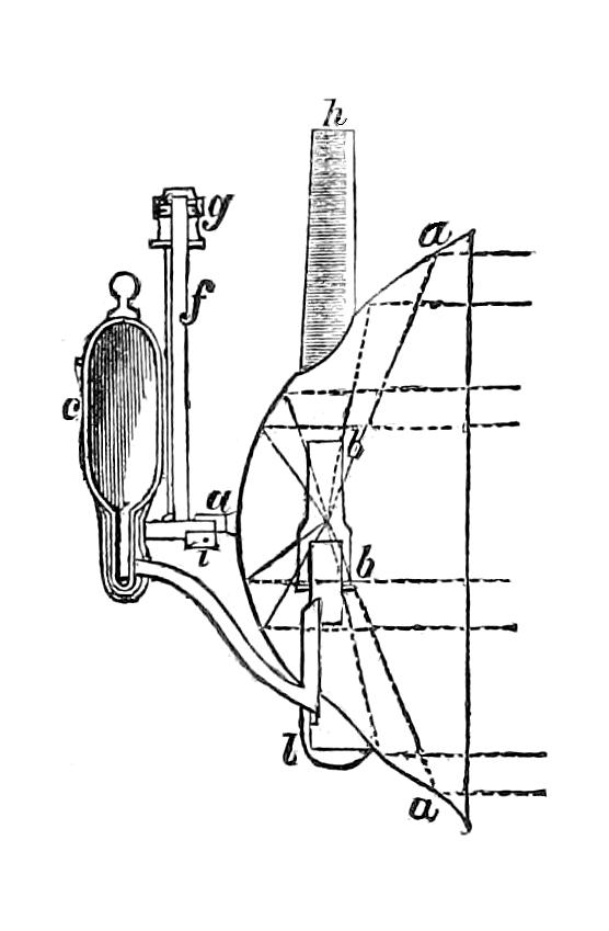
Fig. 29.
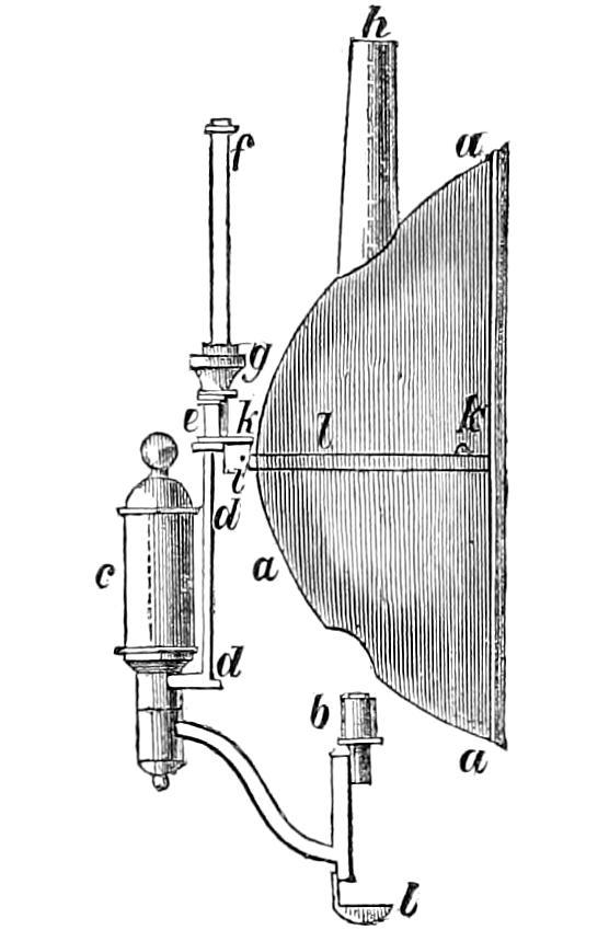
Fig. 30.
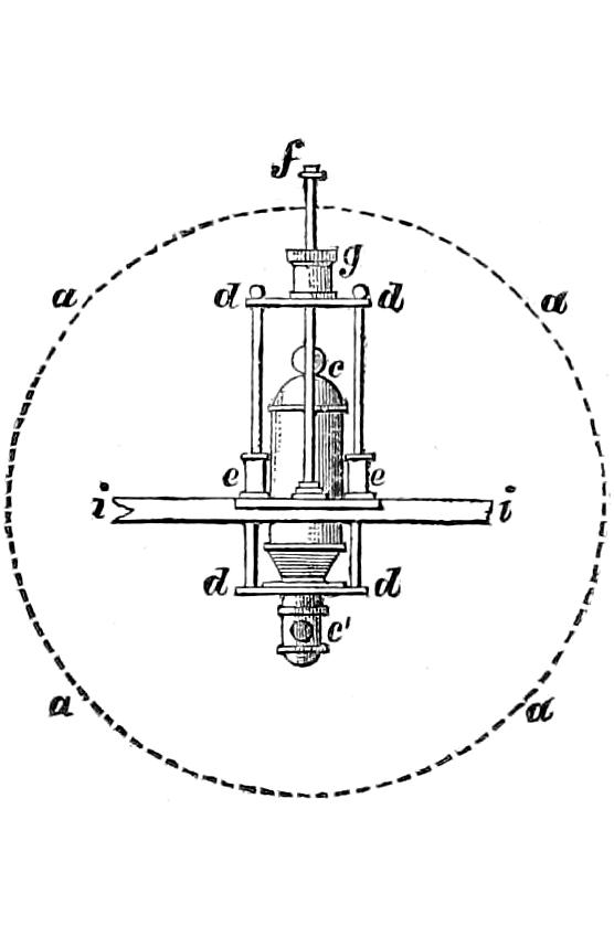
Fig. 31.
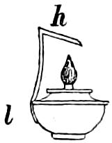
Argand Lamps used in Reflectors. The flame generally used in reflectors, is from an Argand fountain-lamp, whose wick is an inch in diameter. Much care is bestowed upon the manufacture of the lamps for the Northern Lighthouses, which sometimes have their burners tipped with silver to prevent wasting by the great heat which is evolved. The burners are also fitted with a sliding apparatus, accurately formed, by which they may be removed from the interior of the mirror at the time of cleaning them, and returned exactly to the same place, and locked by means of a key. This arrangement, which is shewn in figs. 28, 29, and 30, is very important, as it insures the burner always being in the focus, and does not require that the reflector be lifted out of its place every time it is cleaned; so that, when once carefully set and screwed down to the frame, it is never altered. In these figs. a a a represents one of the reflectors, b is the burner, and c a cylindric fountain, which contains 24 ounces of oil. The oil-pipe, the fountain c for supplying oil, and the burner b, are connected with the rectangular frame d, which is moveable in a vertical direction upon the guide-rods e and f, by which it can be let down, so that the burner may be lowered out of the reflector, by simply turning the handle g (as will be more fully understood by examining figs. 28 and 29), which has the effect of forcing a thread (like that of a screw) on the outside of the guide into a groove in the frame, or withdrawing it, and thus allows it to slide down or locks it at pleasure. An aperture of an elliptical form, measuring about two inches by three, is cut in the upper and lower part of the reflector, the lower serving for the free egress and ingress of the burner, and the upper, to which the copper tube h is attached, serving for ventilation; i shews a cross section and a back view of the main bar of the chandelier or frame on which the reflectors are ranged, each being made to rest on knobs of brass, one of which, as seen at k k, is soldered to the brass band l, that clasps the exterior of the reflector. Fig. 28 is a section of the reflector a a, shewing the position of the burner b, with the glass chimney b′, and oil-cup l, which receives any oil that may drop from the lamp. Fig. 30 shews the apparatus for moving the lamp up and down, so as to remove it from the reflector at the time of cleaning it. In the diagram (fig. 30) the fountain c is moved partly down; d d shews the rectangular frame on which the burner is mounted, e e the elongated socket-guides through which the guide-rods slide, and f the guide-rod, connected with the perforated sockets on which the checking-handle g slides. The oil-cup l (covered with a lid and wick-holder, as shewn in fig. 31) also serves as a frost-lamp during the long nights of winter, when the oil is apt to turn thick. It is attached to the lower part of the oil-tube by the arm h; and is lighted about an hour before sunset, so as to prepare the reflector lamp for lighting at the proper time. The communication between the burner and the fountain is easily opened or shut in the burners used in the Scotch Lighthouses, by simply giving the fountain a turn of one quadrant of the horizon round its own vertical axis by means of the round knob at its top, and thereby moving a simple slide-valve, which shuts off the communication between the fountain-tube and lamp-tube. By this mode, the oil is cut off about fifteen minutes before extinguishing the lights, so that when that is done, the burner is quite free of oil.
Fig. 32.
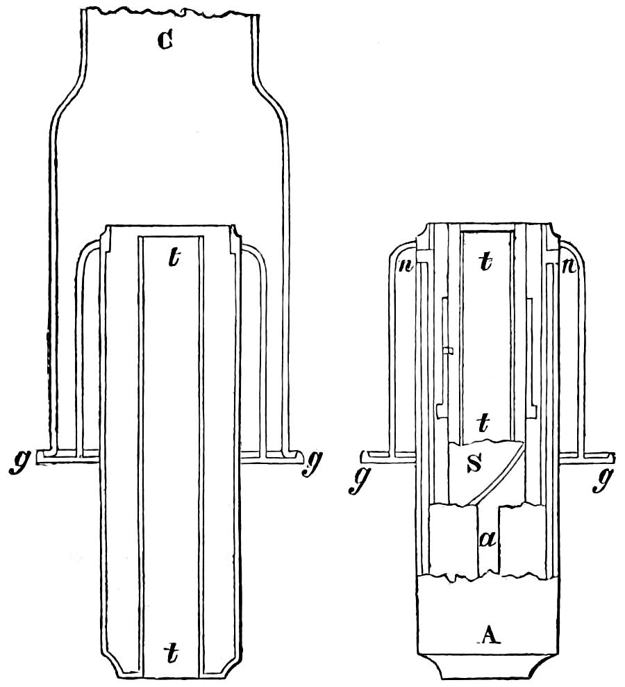
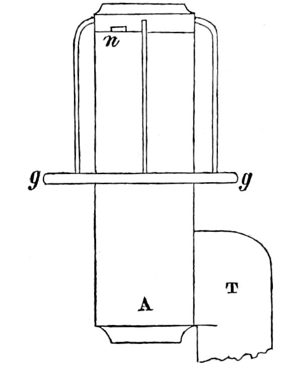
It would needlessly occupy much time and space to describe the various means (many of them sufficiently clumsy) which have been employed, and in many places are still in use, for raising and depressing the wick; it will be enough to say, that they all involve some application of the rack and pinion. Arrangements for Raising or lowering the Argand Wick. I shall, therefore, only describe the method (invented, it is believed, by M. Verzy) which is adopted in all the Lighthouses in the district of the Commissioners of Northern Lights. The arrangement is as follows (see figs. 32, 33, 34, 35, 36):—The inner tube t of the burner is enclosed by a strong tube s, which fits to it tightly, so as not to be easily moved. This strong tube has a spiral groove cut on its outer or convex surface. The wick-holder has two small pegs projecting from it, the one on the inside (not seen), and the other on the outside at a (fig. 33). That on the inside works in the spiral groove of the tube S (figs. 32 and 33), already described as embracing the inner tube t; and all that is required for raising the wick is to make the wick-holder turn round on its vertical axis. This is effected by means of the small external peg a of the wick-holder (fig. 33), which moves in a vertical slit a (figs. 32 and 34), cut in a tube standing in the burner, and concentric with it, and which also moves freely round its axis. Small knobs n n (figs. 32, 34, and 36), at the top of this tube, fit into a notch in the upper ring of the gallery, which supports the glass chimney. By turning this gallery g (see figs. 33 and 36), therefore, motion is given to the tube, with its knobs n n, whose vertical slit a (while it holds the external peg of the wick-holder, and also turns it round along with it) permits that peg a to slide upwards or downwards, and thus the wick-holder rises or falls, according as its own internal peg moves up or down the spiral groove in the tube S. In fig. 32, C shews the glass chimney resting on the gallery g g.
Fig. 33.
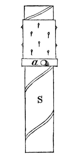
Fig. 34.
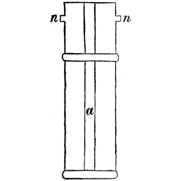
Fig. 35.
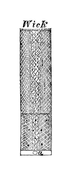
Fig. 36.
An important point in the economy of the Argand lamp, is the level at which the outlet for the oil, in its passage from the fountain to the burner, should be cut. The cutting of this hole (generally called the flow-hole) in the pipe is termed the Flowing of the Lamp. flowing of the lamp, and is commonly done by successive trials, until the oil stands at the proper level of the burner, before the wick is put in. A more ready and accurate method of accomplishing this object and at once determining the level at which the flow-hole should be cut, was introduced by Mr James Murdoch, the Foreman of Lightroom Repairs to the Scotch Board, and is generally employed in the Northern Lighthouses. Its nature will be readily understood by a reference to the accompanying diagram, No. 37:
Fig. 37.
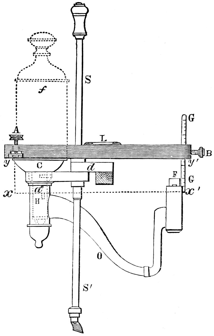
The hatched surface represents a metallic ruler, with a spirit-level at L; C is the cup in which the bottom of the fountain f (shewn in dotted lines) rests. When the fountain is removed, and the ruler rests on the edge of the cup C, the screw at A is used to adjust the level at L; and a gauge GG is allowed to fall until a notch in it at x′ rests on the outer tube of the burner F; the pinching-screw B retains this ruler in its place, and the point x′ indicates the level at which the oil should stand in the burner. The level line x′ x indicates the level on which the top of the flow-hole H should be cut in the fountain-tube, which is shewn in dotted lines within the outer tube, or body of the lamp. In other words, y′ x′ measures the level at which the oil should stand in the burner below the lower edge of the metallic ruler, while the corresponding line y x, at the opposite end, shews the level of the top of the flow-hole H, below the edge of the cup C. The gauge GG applied to that point of the fountain which coincides with the edge of the cup (so that y′ coincides with y) measures the length yx = y′ x′; and a set-square applied at x gives the position of H on the fountain-tube. The round dot at a shews the position of the air-hole in the body of the lamp, which establishes a connection between the external air and the surface of the oil. The rods SS′ shew the sliding gear (described as d and f, page 221), and are only introduced to identify this diagram with those of the fountain and burner which have preceded it.
The most advantageous level of the flow-hole depends on many circumstances too obscure and complicated to admit of any systematic elucidation; and it is enough for all practical purposes, to know that the capillary powers of the wick, and the greater or less viscidity of the oil, are the chief circumstances which determine that level. Actual experience is the only sure guide to the best practice in this respect; and I therefore content myself with stating, that it is generally found that the sperm oil should stand in the empty burner at about ³⁄₈ inch below its top. For colza oil ²⁄₈ inch is sufficient. In summer, owing to the oil being more fluid, there is sometimes a tendency to overflow the burner; but any inconvenience arising from it is avoided by the plan adopted in the Northern Lights, of shutting off the oil (by means of the apparatus already alluded to on p. 222) about fifteen minutes before extinguishing the lights in the morning.
Fig. 38.
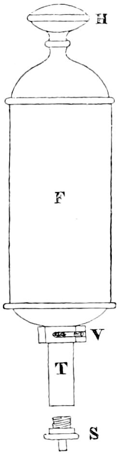
The arrangement for cutting off the oil is very simple, as will be seen from the annexed diagram (fig. 38), in which F is the fountain, T the oil-tube leading to the burner, and V the flow-hole, with its sliding valve. By turning the handle H one quadrant of the circle, the whole fountain F and tube T turn round their vertical axis, while the valve V, which rests in a notch in the cup of the lamp, remains still, and sliding over T, opens the flow-hole. S is the screw-plug which retains the oil in the fountain, and which is unscrewed and removed when the fountain is to be filled.
Fig. 39.
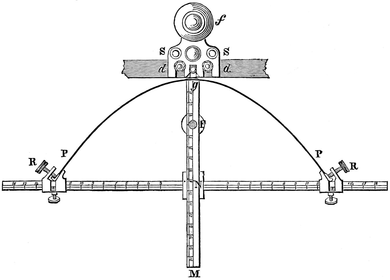
Fig. 40.
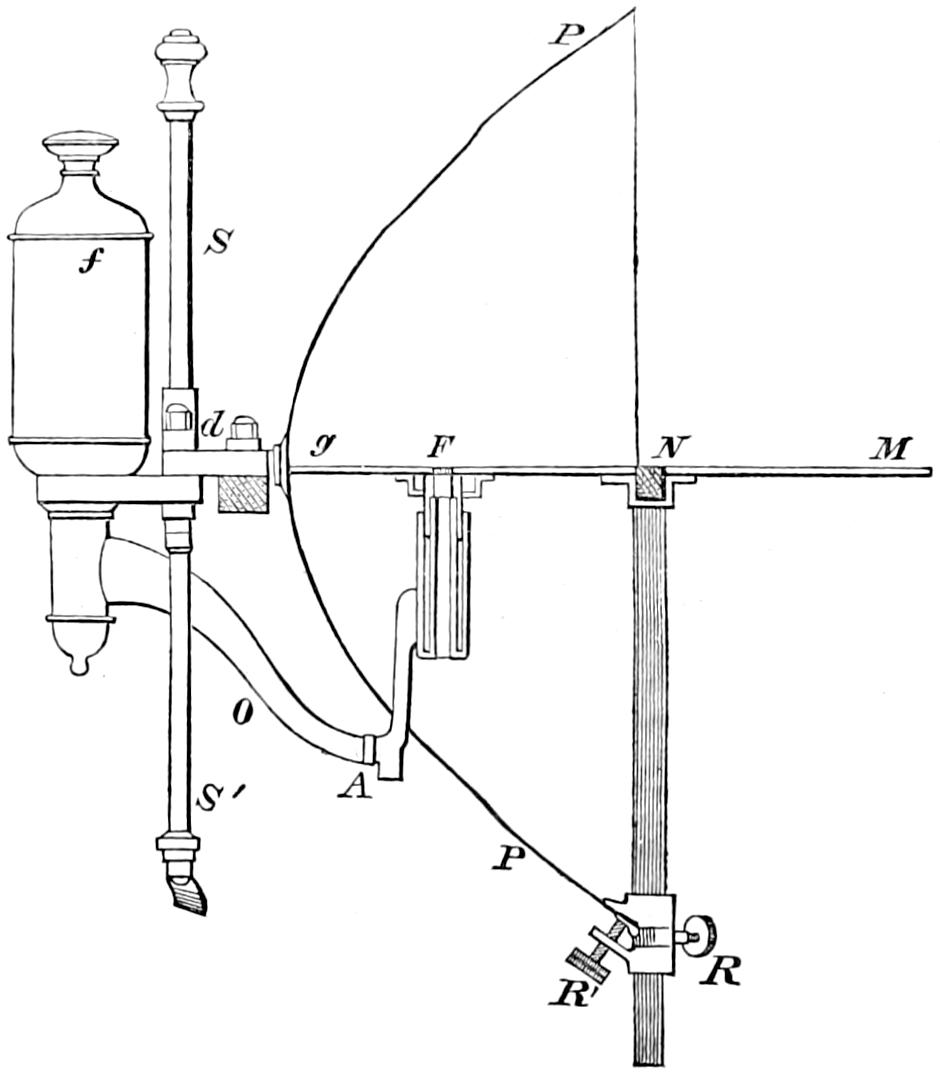
Placing the Lamp in the Focus. In the reflecting apparatus of the Northern Lighthouses, the focal position of the lamp is not, as we have already seen, liable to derangement, by the removal of the burner for the purpose of cleaning, as the sliding gear described at p. 221 insures the return of the lamp to its true place. The burner is originally set by means of a gauge, which touches four points of the mirror’s surface (one of them being its vertex, and the other three in the vertical plane of its greatest double ordinate). This gauge being provided with a short tube or collar properly placed for the purpose of receiving the burner, at once verifies its true position, both vertical and horizontal. The diagrams 39 and 40 shew the nature of the apparatus for adjusting the burners, the one being a plan and the other a section. The four points which touch the curve are one g at the vertex, two in the same horizontal plane with the focus, and near the edge of the mirror at PP, and the fourth, also near the edge, and in the same vertical plane with the focus. F is the focus. The horizontal arms are graduated, and fitted with sliding pieces and clamping screws at R, so as to admit of being varied with the width of the mirror; but each gauge applies only to curves of the same focal distance; the distance F g being fixed. The gauge, when applied to the mirror, is properly secured by the screws at R, R, and R′; and the burner which is attached to the oil-tube in a temporary manner at A, is raised into the interior of the mirror. If the tube of the burner ascends into the circular tube at F until (when fixed by the checking handle already noticed at p. 221) its upper edge just touches a narrow projection inside the tube F (so placed that the rim of the burner should just touch it when it is on the level required for putting the brightest part of the flame in the focus), then the burner is in the proper position; but if, on the one hand, the axis of the burner stands beyond F, at some point between it and N (which lies in the plane of the mirror’s edge), the bent tube O from the fountain must be shortened at A; and if it rise too high, that tube must be bent down (and vice versa), until, by successive trials, it shall exactly fit into the tube F, and stand at the proper level. A skilful workman soon comes to guess those quantities very accurately; and, almost at the first trial, curtails the tube to the proper length, and bends it to the suitable level. All that is needful is to proceed cautiously, so as not to cut the tube too short, for this leads to some trouble.
The great advantage derived by seamen from the establishment of lights on a coast, soon makes the calls for additional lights so frequent, that their very number itself produces a new evil, in the difficulty of distinguishing the lights from each other. As the object of a light is to make known to the benighted mariner the land he has made, with as much certainty as the sight of a hill or tower would shew him his position during the day, it becomes an object of the first importance to Distinctions of Catoptric Lights. impress upon each light a distinctive character, which shall effectually prevent the possibility of its being mistaken for any other.
Catoptric lights are susceptible of nine separate distinctions, which are called fixed, revolving white, revolving red and white, revolving red with two whites, revolving white with two reds, flashing, intermittent, double fixed lights, and double revolving white lights. The first exhibits a steady and uniform appearance, which is not subject to any change; and the reflectors used for it (as already noticed) are of smaller dimensions than those employed in revolving lights. This is necessary, in order to permit them to be ranged round the circular frame, with their axes inclined at such an angle, as shall enable them to illuminate every point of the horizon. The revolving light is produced by the revolution of a frame with three or four sides, having reflectors of a larger size grouped on each side, with their axes parallel; and as the revolution exhibits once in two minutes, or once in a minute, as may be required, a light gradually increasing to full strength, and in the same gradual manner decreasing to total darkness, its appearance is extremely well marked. The succession of red and white lights is caused by the revolution of a frame whose different sides present red and white lights; and these, as already mentioned, afford three separate distinctions, namely, alternate red and white; the succession of two white lights after one red, and the succession of two red lights after one white light. The flashing light is produced in the same manner as the revolving light; but owing to a different construction of the frame, the reflectors on each of eight sides are arranged with their rims or faces in one vertical plane, and their axes in a line inclined to the perpendicular, a disposition of the mirrors which, together with the greater quickness of the revolution, which shews a flash once in five seconds of time, produces a very striking effect, totally different from that of a revolving light, and presenting the appearance of the flash alternately rising and sinking. The brightest and darkest periods being but momentary, this light is farther characterised by a rapid succession of bright flashes, from which it gets its name. The intermittent light is distinguished by bursting suddenly into view and continuing steady for a short time, after which it is suddenly eclipsed for half a minute. Its striking appearance is produced by the perpendicular motion of circular shades in front of the reflectors, by which the light is alternately hid and displayed. This distinction, as well as that called the flashing light, is peculiar to the Scotch coast, having been first introduced by the late Engineer of the Northern Lights Board. The double lights (which are seldom used except where there is a necessity for a leading line, as a guide for taking some channel or avoiding some danger) are generally exhibited from two Towers, one of which is higher than the other. At the Calf of Man, a striking variety has been introduced into the character of leading lights, by substituting, for two fixed lights, two lights which revolve in the same periods, and exhibit their flashes at the same instant; and these lights are, of course, susceptible of the other variety enumerated above, that of two revolving red and white lights, or flashing lights, coming into view at equal intervals of time. The utility of all these distinctions is to be valued with reference to their property of at once striking the eye of an observer and being instantaneously obvious to strangers.
The introduction of colour, as a source of distinction, is necessary, in order to obtain a sufficient number of distinctions; but it is in itself an evil of no small magnitude; as the effect is produced by interposing coloured media between the burner and the observer’s eye, and much light is thus lost by the absorption of those rays, which are held back in order to cause the appearance which is desired. Trial has been made of various colours; but red, blue, and green alone have been found useful, and the two latter only at distances so short as to render them altogether unfit for sea-lights. Owing to the depth of tint which is required to produce a marked effect, the red shades generally used absorb from ⁴⁄₇ths to ⁵⁄₆ths of the whole light, an enormous loss, and sufficient to discourage the adoption of that mode of distinction in every situation where it can possibly be avoided. The red glass used in France absorbs only ⁴⁄₇ths of the light; but its colour produces, as might be expected, a much less marked distinction to the seaman’s eye. In the Lighthouses of Scotland, a simple and convenient arrangement exists for colouring the lights, which consists in using chimneys of red glass, instead of placing large discs in front of the reflectors.
Fig. 41.
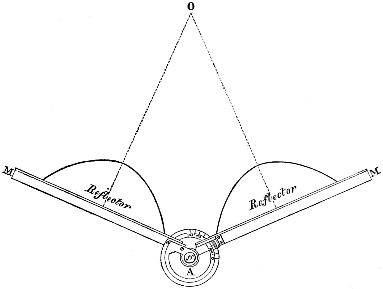
After what has been already said on the subject of divergence, it will at once be seen, that in revolving lights the reflectors are placed with their axes parallel to each other, so as to concentrate their power in one direction; whilst in fixed lights it is necessary, in order to approach as near as possible to an equal distribution of the light over the horizon, Arrangement of Reflectors on the Frame. to place the reflectors, with their axes inclined to each other, at an angle somewhat less than that of the divergence of the reflected cone. For this purpose, a brass gauge (see fig. 41), composed of two long arms, AM, AM, somewhat in the form of a pair of common dividers, connected by a means of a graduated limb A, is employed. The arms having been first placed at the angle, which is supplemental to that of the inclination of the axes of the two adjacent mirrors at O, are made to span the faces of the reflectors, one of which is moved about till its edges are in close contact with the flat surface of one of the arms of the gauge.
Fig. 42.
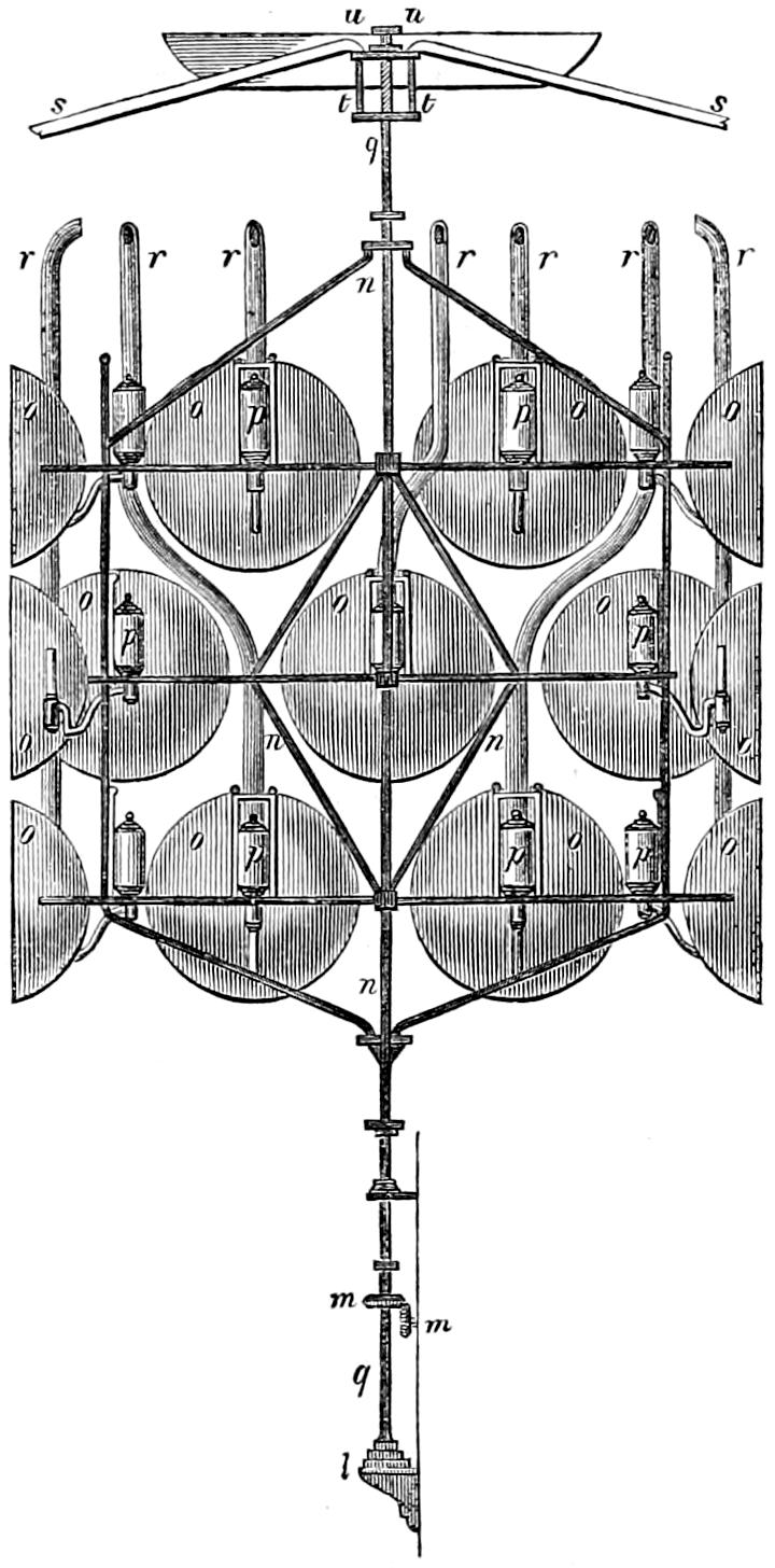
Fig. 43.
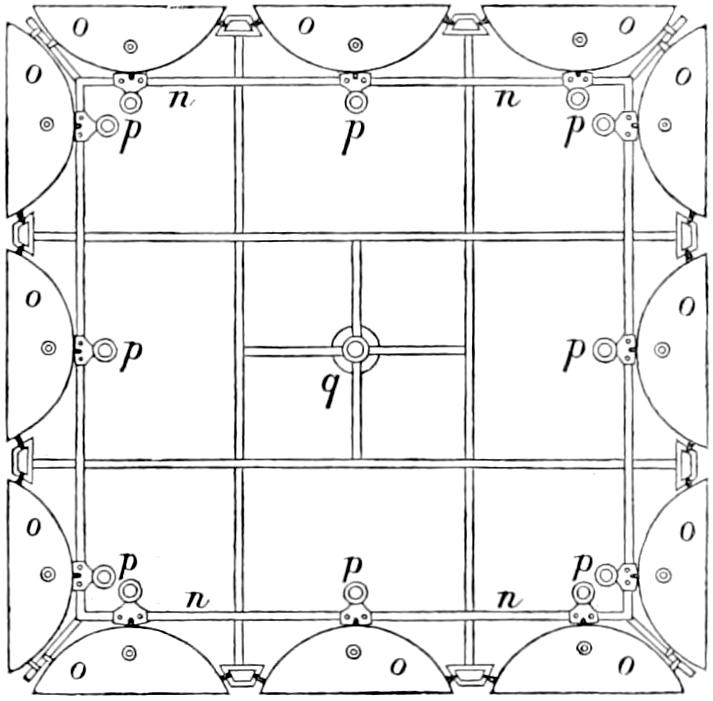
Figs. 42 and 43 shew an elevation and plan of a revolving apparatus on the catoptric principle. In these figures, n n shews the reflector frame or chandelier; o o, the reflectors with their oil-fountains p p. The whole is attached to the revolving axis or shaft q. The copper tubes r r convey the smoke from the lamps; s s are cross bars which support the shaft at t t; u u is a copper pan for receiving any moisture which may accidentally enter at the central ventilator in the roof of the light-room; l is a cast-iron bracket, supporting the cup in which the pivot of the shaft turns; m m are bevelled wheels, which convey motion from the machine to the shaft. The machinery does not require any particular notice, being that of common clock-work, moved by the descent of a weight.
Fig. 44.
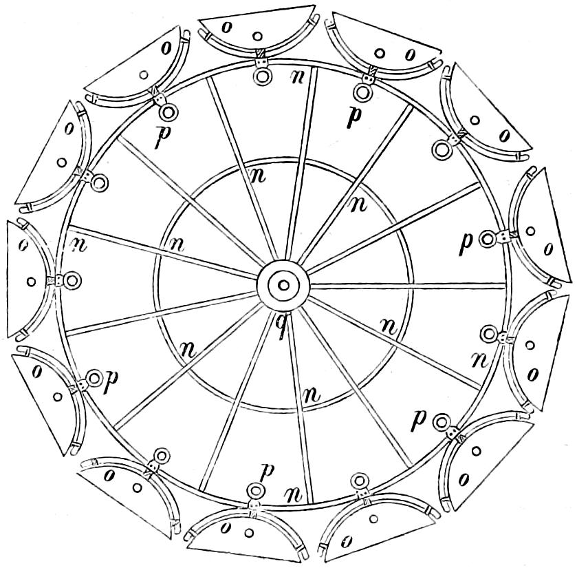
Fig. 44 shews a plan of one tier of reflectors arranged in the manner employed in a fixed catoptric light; n n shews the chandelier, q the fixed shaft in the centre, which supports the whole, o o the reflectors, and p p the fountains of their lamps. In this figure (in order to prevent confusion) only one tier of reflectors is shewn; the other tiers are so arranged, that their axes divide into equal angles the arcs intercepted between the axes of the adjoining reflectors on the first tier, thereby producing the nearest approach to an equal distribution of the light, which is attainable by this arrangement.
In lighthouses of moderate height, the proper position for the reflector itself is perfect horizontality of its axis, which may be ascertained with sufficient accuracy, by trying with a plummet, whether the lips of the instrument, which we may conclude to be at right angles to the plane of its axis, be truly vertical. In lightrooms very much elevated above the sea, however, the dip of the horizon becomes notable; and a slight inclination forwards should be given to the face of the reflectors, so that their axes produced may be tangents to the earth at the visible horizon of the light-room. This, however, must not be permitted to interfere with the perfect horizontality of the top of the burner, which is indispensable to its proper burning.
Bordier Marcet’s Reflectors. Various forms of the parabolic mirror were invented by M. Bordier Marcet, the pupil and successor of Argand, who has laboured with much enthusiasm in perfecting catoptric instruments, more especially with a view to their application in the illumination of lighthouses and the streets of towns. Amongst many other ingenious combinations, he has invented and constructed an apparatus which is much used in harbour-lights on the French coast, where it is known by the fanciful name of Fanal Sidéral. Fanal[46] sidéral. The object is to fulfil, as economically as possible, the conditions required in a fixed light, by illuminating, with perfect equality, every part of the horizon, by means of a single burner; and M. Bordier Marcet has in his work-shop an instrument of this kind, eight feet in diameter, which he constructed on speculation. The apparatus used in harbour-lights, on the French coast, is of much smaller dimensions, and does not exceed fifteen inches in diameter. A perfect idea of the construction and effect of this instrument may be formed, by conceiving a parabola to revolve about its parameter as a vertical axis, so that its upper and lower limbs would become the generating lines of two surfaces possessing the property of reflecting, in lines parallel to the axis of the parabola, all the rays incident upon them, from a light placed in the point where the parameter and axis of the generating parabola intersect each other. This point being the focus of each parabolic section of this apparatus, light is equally dispersed in every point of the horizon, when the axis of the parabolic section is in a plane perpendicular to a vertical line. But however perfectly this apparatus may attain its important object, it necessarily produces a feeble effect; because as its action is entirely confined to the vertical direction, the light distributed by it decreases directly as the distance of the observer. This beautiful little instrument is shewn at fig. 45, in which b shews the burner, p p the upper reflecting surface, and p′ p′ the lower reflecting surface, both generated in the manner above described by the revolution of a parabola about its parameter x b; F is the focus of the generating parabola; and l l are small pillars, which connect the two reflecting plates, and give strength to the apparatus.