Part 2 — APPENDIX.
Reading edition
APPENDIX, No. I. TABLE OF CO-ORDINATES OF AN HYPERBOLIC COLUMN WHOSE DIAMETER AT THE TOP = 16 FEET, AT THE BASE = 42 FEET, AND HEIGHT = 120·25 FEET.
The column is generated by the revolution of a rectangular hyperbola about one of its asymptotes. In the annexed figure (No. 98), a f is the height of the column, a c and f h the radii of its base and top; and we have to determine the particular hyperbola which will pass through the points c, h.
Putting b e = x; e g = y, the equation to the curve, referred to its asymptotes, is
x y = a²2,
in which the value of the constant a² 2 is to be found. For this purpose we have the conditions a c = 21; f h = 8; and a f = 120·25. Let the co-ordinates of the point c be x′, y′, and of h, x″, y″, then y′ = 21; y″ = 8; x″ = x′ + 120·25.
Fig. 98.
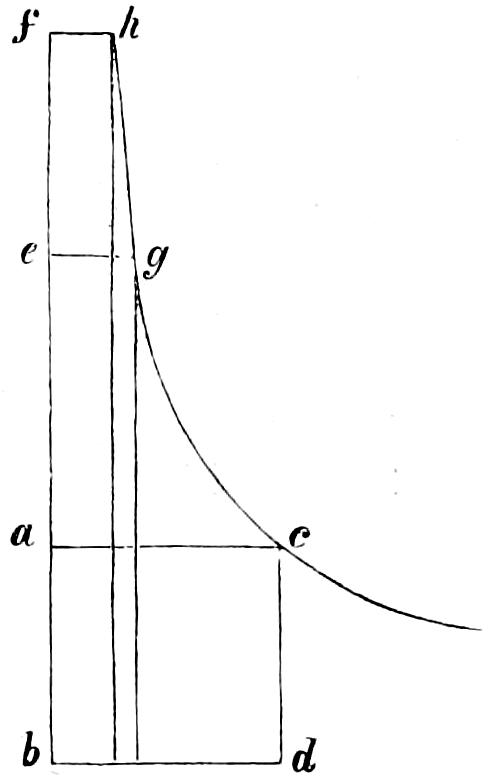
And since x′ y′ = a²2 = x″ y″
we have 21 x′ = 8 (x′ + 120·25)
from which x′ = 74
and a²2 = x′ y′ = 74 × 21 = 1554.
Therefore x y = 1554.
Transferring the origin to a, x becomes x - x′ = x - 74, and y (x - 74) = 1554, and the required equation by which the following Table was computed is, y = 1554 x - 74.
Table of the Radii of the Hyperbolic Column at each foot of its Height.
Height. Radius. Height. Radius. Height. Radius. Height. Radius.
0 21·000 31 14·800 62 11·426 93 9·305
1 20·720 32 14·660 63 11·343 94 9·250
2 20·447 33 14·523 64 11·261 95 9·195
3 20·182 34 14·389 65 11·180 96 9·141
4 19·923 35 14·257 66 11·100 97 9·088
5 19·671 36 14·127 67 11·021 98 9·035
6 19·425 37 14·000 68 10·944 99 8·983
7 19·185 38 13·875 69 10·867 100 8·931
8 18·951 39 13·752 70 10·792 101 8·880
9 18·723 40 13·632 71 10·717 102 8·830
10 18·500 41 13·513 72 10·644 103 8·780
11 18·282 42 13·397 73 10·571 104 8·730
12 18·070 43 13·282 74 10·500 105 8·681
13 17·862 44 13·170 75 10·430 106 8·633
14 17·659 45 13·059 76 10·360 107 8·586
15 17·461 46 12·950 77 10·291 108 8·539
16 17·267 47 12·843 78 10·224 109 8·492
17 17·077 48 12·738 79 10·157 110 8·446
18 16·891 49 12·634 80 10·091 111 8·400
19 16·710 50 12·532 81 10·026 112 8·355
20 16·532 51 12·432 82 9·962 113 8·310
21 16·358 52 12·333 83 9·898 114 8·266
22 16·188 53 12·236 84 9·835 115 8·222
23 16·021 54 12·141 85 9·774 116 8·179
24 15·857 55 12·046 86 9·712 117 8·136
25 15·697 56 11·954 87 9·652 118 8·094
26 15·540 57 11·862 88 9·593 119 8·052
27 15·386 58 11·773 89 9·534 120 8·010
28 15·235 59 11·684 90 9·476 120·25 8·000
29 15·087 60 11·597 91 9·418 ... ...
30 14·942 61 11·511 92 9·361 ... ...
APPENDIX, No. II. NOTES ON THE MANUFACTURE OF PARABOLOÏDAL REFLECTORS, from Information furnished by Mr James Murdoch, of the Northern Lights Service.
Fig. 99.
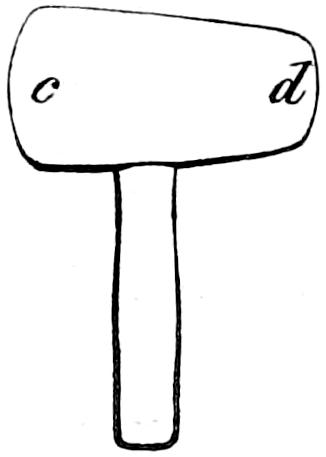
The reflector-plate consists of virgin-silver and the purest copper (from the ingot), in the proportion of 6 oz. of silver to 16 oz. of copper. The two metals are in pieces, forming a flat parallelopepid of about nine inches of surface. Being first thoroughly scraped and cleared from rust with a file, they are tied together with wire and placed in the furnace, where they are united by means of a flux composed of burnt borax and nitre, mixed to the consistence of cream. Their thickness is sufficient to admit of their being repeatedly passed through the rolling-mill, so as at last to come out a plate twenty-eight inches square. Every time it is passed through the rollers, the plate is annealed in the furnace before being again pressed. It is then cut into a circular disc ready for working; and great care should be taken to keep the metal perfectly clean during the whole of the hammering and polishing processes. The first step towards forming the plate to the curve, is to raise the back or copper side to a slight convexity by beating, with the boxwood mallet (fig. 99), rounded at each end, c and d, its inner or silver side upon a large block of beechwood, of a form slightly concave. This beating is begun at the edge of the plate, and gradually reaches the centre. After the disc has been raised to the proper height on the wooden block, the next step is to take it to the horse (fig. 103, opposite page), where it is beaten with the wooden mallet (fig. 100), its concave face being in contact with the bright steel-head a (fig. 103), until it has nearly reached the proper height for the reflector, for which the workman has a gauge or mould to guide him; in this course of raising, as it is called, the peened face b a b (fig. 100) is first used, and then recourse is had to the opposite or flat face for smoothing it after being raised. In this last course of raising, as well as in the process of smoothing the reflector all over, the workman bestrides the horse.
Fig. 100.
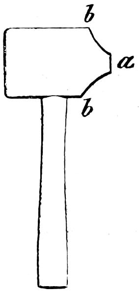
Fig. 101.
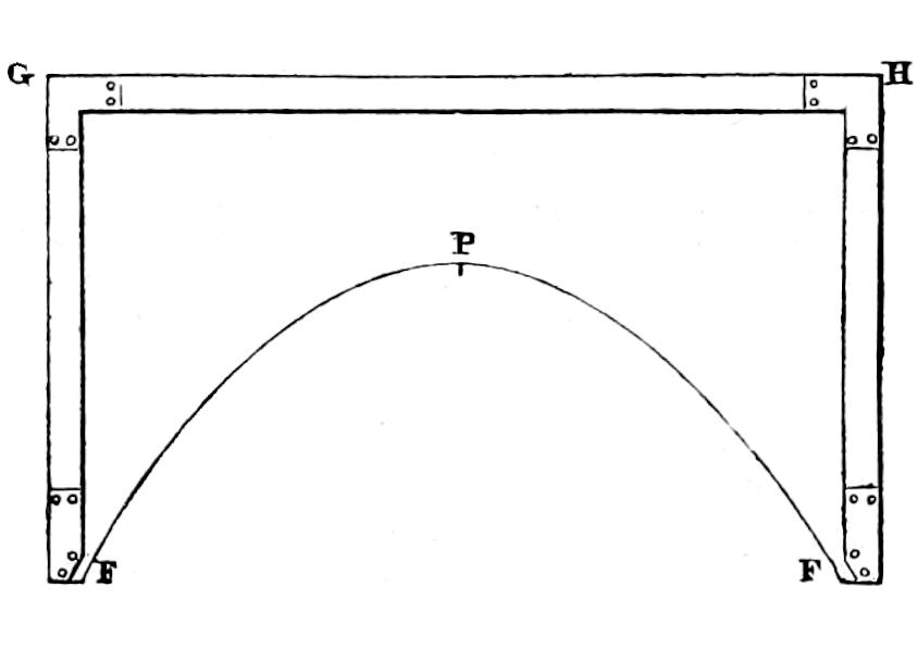
During the process of raising with the peened side of the mallet, an external mould FGHF (fig. 101), with a needle-point P, at its vertex, is applied, to indicate its proper position with reference to the mould; and allowance is made on the height and diameter of the reflector to meet the expansion of the metal during the hard-hammering which is to follow. After each course of the raising with the wooden mallets, the reflector must be annealed in the following manner:—The reflector is first damped with clean water, and its surface dusted over with a powder, composed of one pint of powdered charcoal to one ounce of saltpetre, which is applied by means of a thin flannel bag. The reflector is then put on a clear charcoal fire, where it is turned round as the powder flies off, which is an indication that the metal is duly heated. Over-heating is very injurious. When removed from the fire, the reflector is plunged into a large tub, containing what is called the pickle, which is a solution of one quart of vitriol in five or six gallons of water. After this it is washed with clean water, and scoured with Calais sand.
The next step is to put the reflector, thus raised nearly to its true form, into an iron stool, where a small hole being drilled in its vertex, a circle is described from this point with a beam-compass, so as to cut the paraboloïd to the proposed size.
Fig. 102.
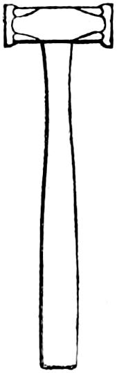
Fig. 103.
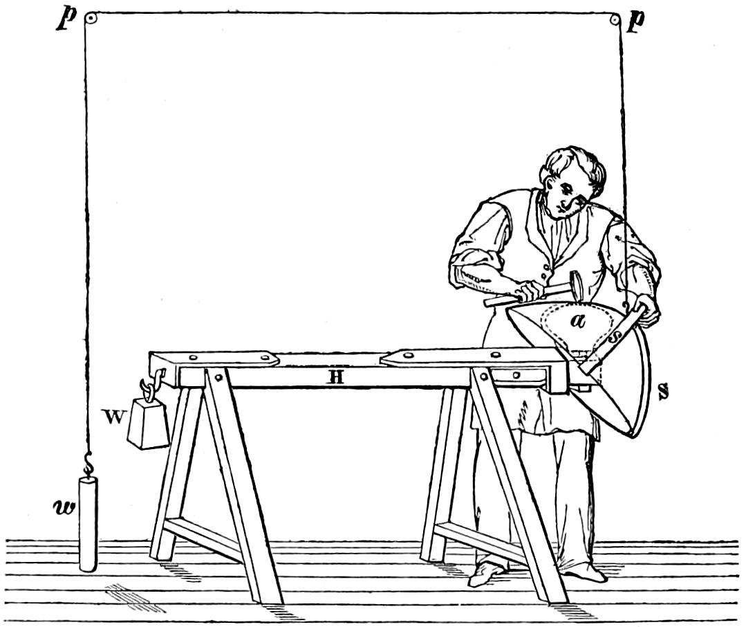
Fig. 104.
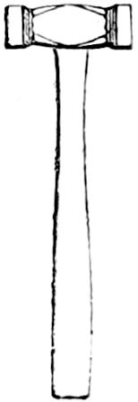
Fig. 105.
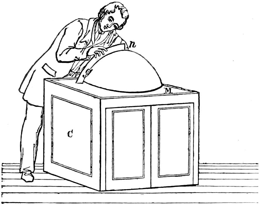
The reflector is next hard-hammered all over (or planished, as it is technically termed) on the bright steel-head a (fig. 103), with the planishing hammer (fig. 102); and to facilitate working, the reflector is slung in a flexible frame SS, and counterbalanced by a weight w, hanging by a cord over the pulleys p p. When the reflector is all planished over, the next process is the smoothing, which is done on the steel-head a, with a lighter hammer (fig. 104 ), muffled with fine parchment at each end. After it is smoothed comes the finishing, or what is called the filling up to the mould. This is a tedious process, and the workman requires continually to have recourse to the marble table at M, on which he lays the reflector, as shewn in fig. 105, and applies to successive portions of its surface the mould g n, which has a needle-point centred at n, in the small hole drilled in the vertex. During this examination, he marks with a fine slate-pencil those portions of the reflector which do not meet the mould g n. The parts, so marked, are gently gone over with the muffled hammer, until every point touches the mould. This last process requires great caution; for, if any part of the surface be raised above the gauge, it is hardly possible to remedy it. Such a mistake, indeed, can only be corrected by annealing the reflector afresh, and bringing it back to the true form with the mallet; but reflectors so cobbled are never good. The table M (fig. 105) rests on a square box C, in which the tools and moulds are kept.
Fig. 106.
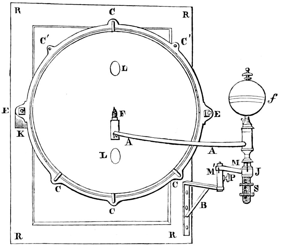
When thus finished from the hammer, the reflector is put into the apparatus shewn in fig. 106, which is placed at the end of a long dark corridor. RR is a wooden frame fixed to the wall with projecting brackets at K, which carry the reflector, fixed at E, E, by means of screws, so as always to have a definite position with reference to the bracket B, which carries the lamp and its fountain f, so arranged that its flame may admit of perfect adjustment to the point which ought to be the focus of the reflector. For the purpose of this adjustment, S shews screws for raising and depressing the level of the burner; and the lines or marks M, M′ shewn at the sockets J being brought into line, regulate the position of the burner in the plane of the focus, after it has been raised to the level of that plane by means of the screws at S. The lamp being lighted and thus properly placed, its effect on the reflector’s surface is observed by some one stationed at a convenient distance; and if the whole surface appear luminous, the instrument is considered fit for polishing; but if any dark spaces be found in it, the whole reflector must be again carefully tested by means of the mould, and the defective parts remedied in the manner above described.
The next step is to turn over the edge of the reflector, so as to stiffen it. For this purpose it is placed in the matrix P′P′ (fig. 107), and the needle-point at V is adjusted by the screw at D, so as just to enter the small hole formerly drilled in the vertex of the reflector. The die-plate PP (which is worked by means of the arms AA, which turn the screw S) then descends and presses the edge over, which is finished with a finely polished tool C, revolving round the axis of the instrument, which coincides with the centre of the matrix and die. In order to ensure a steady vertical movement of the die-plate PP, cross-arms FF, which are provided with sockets HH, which slide over the rods GG, GG, are added to prevent any lateral shake or derangement. The whole frame is stiffened by the cross-head in which the screw S works.
Fig. 107.
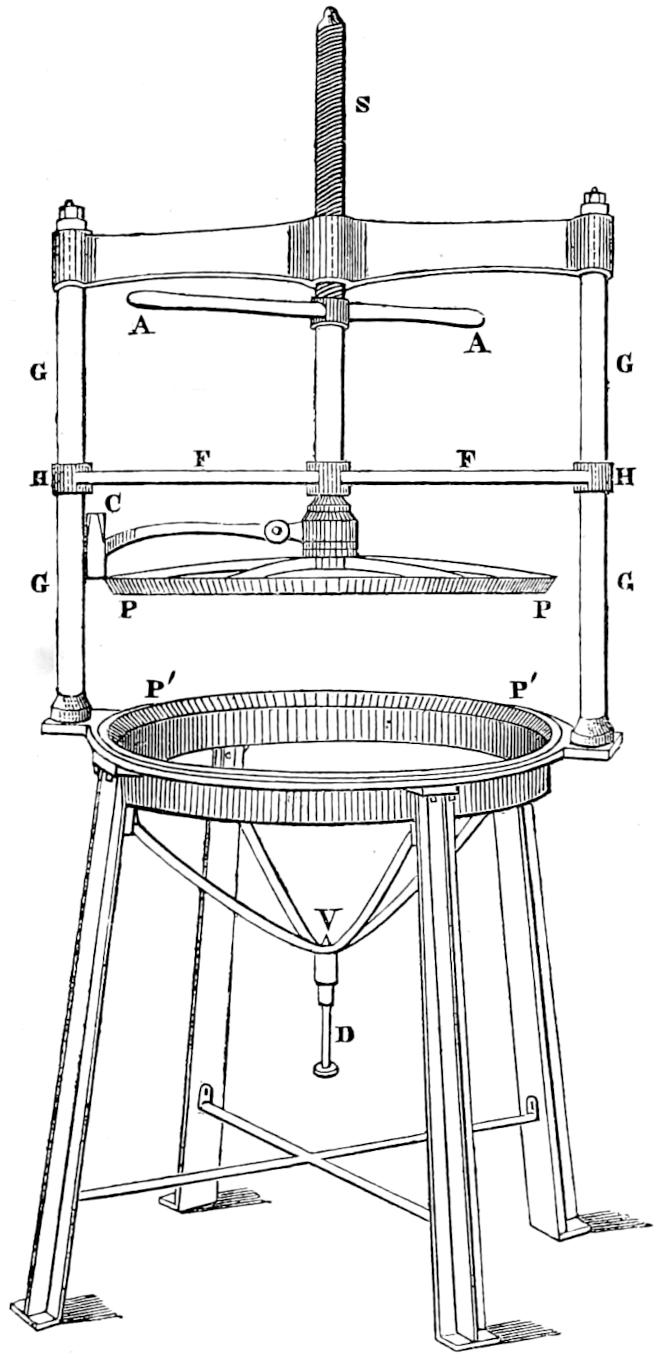
Fig. 108.
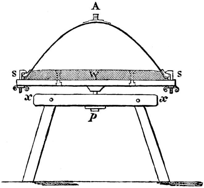
Fig. 109.
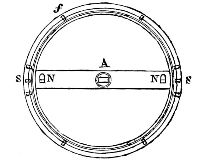
The reflector is then placed on the circular cast-iron table (figs. 108, 109), to which it is attached by the clamp-screws S, S. In this position, the bizzle W (fig. 108) and back-belt NAN (fig. 109), are soldered on. After this the reflector is ready for being finally polished; for which purpose, it is placed in a chaise percée, padded round the edges, and is first scoured all over with a piece of pure charcoal of hard wood, and next with a mixture of Florence oil and finely washed rottenstone, applied by means of a large ball of superfine cloth. It is then carefully cleansed with a piece of fine flannel dipped in Florence oil, and afterwards dusted over with the powder of well washed whiting, and wiped out with a soft cotton cloth. Lastly, it is carefully rubbed by the naked hand, with finely washed rouge and clean water, and wiped with a smooth chamois skin. In all the polishing and cleansing processes, some skill in manipulation is required, as the hand is generally moved in such a manner as to describe successive circles with their planes parallel to the lips of the reflector, and their centres in the axis of the generating curve.
The prices paid to the workmen for the various departments of the reflector-making are generally as follows:—
Raising the plate to the curve, with the wooden mallet, L.0 10 0
Hammering and smoothing to the mould, 1 5 0
Finishing in the die, and putting on bizzle and back-belt, 0 6 0
Polishing, 0 12 0
L.2 13 0
The prices paid to the manufacturer were for the large reflectors of 24 inches aperture, L.43; for the small ones of 21 inches, L.31, 12s. The lamp with the sliding-carriage, required for each, costs L.6.
APPENDIX, No. III. NOTES ON THE GRINDING OF THE VARIOUS PIECES COMPOSING THE INSTRUMENTS USED IN DIOPTRIC LIGHTHOUSES, CHIEFLY FROM NOTES FURNISHED BY M. THEODORE LETOURNEAU OF PARIS.
The glass used in all the parts of the optical apparatus of the dioptric Lighthouses is that of St Gobain, whose index of refraction is 1·51.
As well on account of the difficulty experienced in producing at all times regular castings of glass from the moulds, as in order to compensate for the frequent accidents, which occur in the first application of the rubbers to the inequalities of the surface of the glass, the castings, whether for rings of lenses or prisms, are made from moulds, exceeding the intended size of the finished pieces by one-eighth part.
We shall take as an example, which is well calculated to illustrate the difficulties of the grinding process, one of the prismatic rings of a Catadioptric Light of the first order. The first operation will be to take off the rough arris at the angles of the pieces as they come from the moulds, and to reduce to equality the length of each of the four quadrantal prisms or segments by removing from each the quantity that may be necessary to make those four pieces, when placed on a circle, exactly equal to that of the finished zones. Each of them must have an excess of material at the various surfaces just sufficient to insure the rubber having scope enough to remove all the flaws or defects of the two surfaces to be first ground, which are the (concave and convex) refracting faces of the zone (the sides AC and BC in the Table in the Appendix, No. IV.)
Fig. 110.
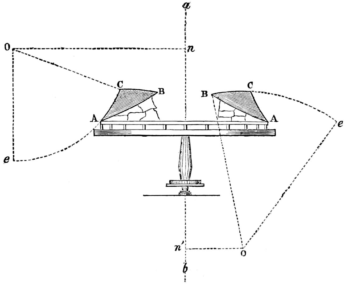
The pieces must be placed end to end on the horizontal plane or table of the lathe at AA (fig. 110), and must rest on the exterior arris A of the reflecting side, on which arris there is ground a narrow plane whose width is proportionate to the projection of the outer edge beyond the inner edge of the zone, foreshortened by the bevel or inclination of the reflecting side, when resting (as in fig. 110) on the circular iron belt, which is screwed to the table of the lathe provided for its reception. This narrow plane at the arris A should be sufficient to give the prism a solid and regular bearing on the circular iron belt. In this figure (fig. 110) a b is the vertical axis of the lathe, n the point from which the co-ordinates for O, the grinding centre for the exterior concave refracting surface AC, are measured, and e AC the arc swept by the grinding surface. Conversely, n′ is the origin of the co-ordinates for the grinding centre O of the interior convex refracting surface BC, and e CB the arc swept by its grinding surface. Some skill is required in fixing the prism on the belt, for, on the one hand, there is an obstacle to correct workmanship from the dragging motion of the platform, and, on the other, by the unequal subdivision of the weight of the glass, which should be nearly balanced. This narrow plane being perfectly adjusted for all the segments so as to bed them quite level, the circular iron belt on which the ring should be ground, is placed on its platform, in the manner represented in the figure. It should be as truly levelled as possible, otherwise all the subsequent operations will be deranged by it. This iron belt is heated by means of heating pans; and the degree of heat may be practically judged of by the ebullition of drops of water let fall on it. The segments of glass are also at the same time placed in a stove heated with steam, and are generally raised to about 120° centigrade. The difference between the time required for the two operations of heating the iron belt and the glass segments is employed in laying or bedding a quantity of cement on the reflecting side of the segment, so as to fill up the angular space between the glass and the iron belt, and also to serve as a seat for the segment in the manner shewn in fig. 110. This operation is performed on a plane surface, in order that the lower part of the mastic may be precisely on a level with the narrow plane already ground on the outer arris of the reflecting side. After being sure that the heat is equally spread over every part of the circular iron belt, the segment is arranged on it; and the workman must, at this juncture, exert all his skill in placing the parts of the segment in a position nearly concentric with the belt, or in a truly circular form, making due allowance, however, for the inequalities existing at various parts of the rough material, and at the same time taking care that there should be an interval of at least two millimètres (or about ¹⁄₁₂th inch) between the ends of each of the two adjacent segments. Without this interval the heat evolved during the polishing would either dilate the glass so much as to cause the ends of the segments to fly into splinters, or make it needful to remove the zone before this should take place, the inevitable consequence of which would be the fracture of the pieces. Those intervals between the segments are filled with statuary’s plaster, which must be carefully washed and brushed at each change of the emery employed in grinding.
The exterior diameter of the circular iron belt must be precisely equal to that of the ring, because, if larger, the free movement of the rubbers to and fro on the concave refracting surface AC (fig. 110) could not take place.
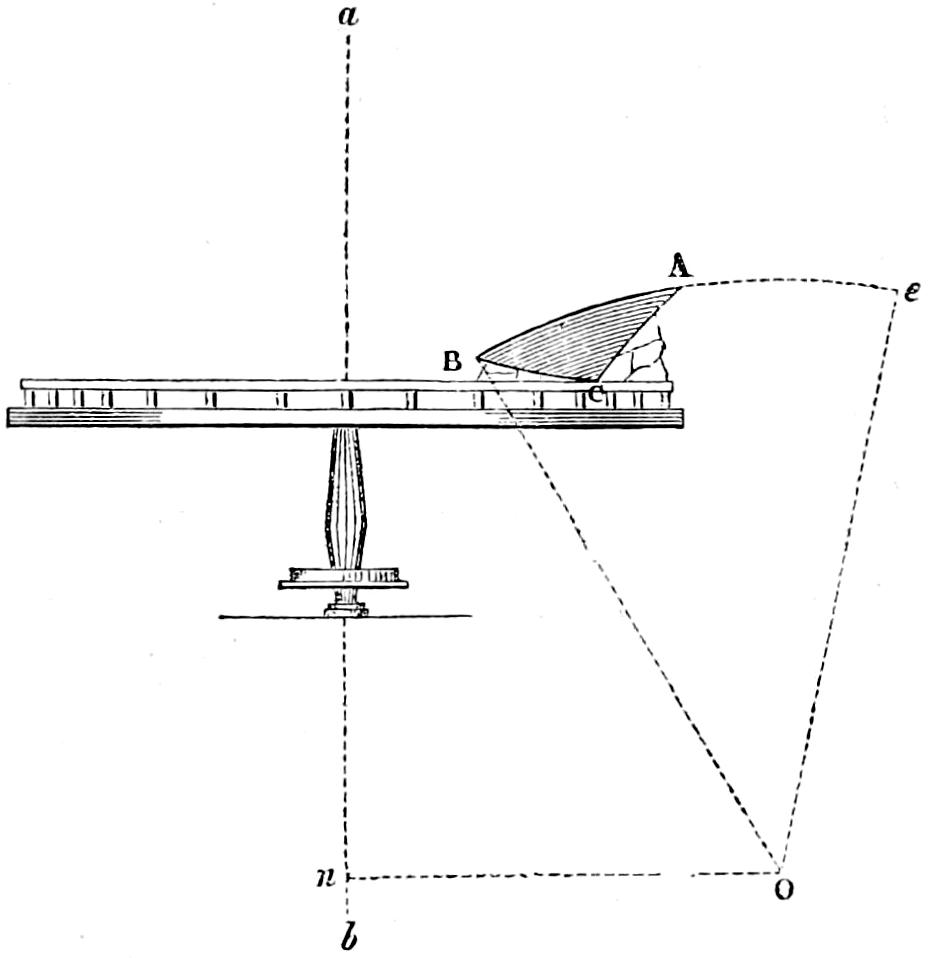
By what is already said, it will be obvious that the grinding process is begun at the refracting sides AC and BC, and a few words will shew that this could hardly be otherwise. If a commencement be made on the reflecting side, which appears at first sight more natural, the consequence is obvious. Having provided for an excess of material in every direction, the segment must consequently be larger than it will be when finished; and the surfaces therefore cannot be true and perfect, except they be ground throughout their entire segmental section, from their centres of curvature, in reference to some given apex of the generating triangle. Now, if the reflecting side were finished first, it might continue to possess this excess of size after being finished, and would, therefore, afford no accurate starting point for the grinding of the other surfaces; it would also present no surface or narrow plane for resting firmly on the iron belt, but would then depend merely on its own finished plane, which, being curved and considerably inclined, would not give a solid bearing for the glass. The other mode of commencing with the two refracting sides, on the contrary, gives a solid bearing on the narrow plane already ground on the reflecting side at A; and after these surfaces have been ground, and the segments inverted (as shewn in fig. 111), the outer edge of this narrow plane at the arris A, which has been fully defined by the intersection of the finished surface AC just ground, and also the apex at C, which has been determined by the intersection of AC and BC, combine to fix an accurate starting point for the rubber, in grinding the reflecting surface AB.
Fig. 111.
Dressing off the rough part of the Ring.
The ring is generally reduced from the rough state by means of fixed rubbers, the adjustment of which is more easily regulated than that of the moveable beam or radius of the arc, which is used to give the exact curvature of the surface. Those fixed rubbers are 150 millimètres (nearly 6 inches) wide, by 200 millimètres (nearly 8 inches) long, and are of cast-iron. Three such rubbers are placed at equidistant points of the circle. Two cutters of sheet-iron attached to arms placed vertically (as are also those which carry the rubbers), and moving in grooves radiating towards the centre of the lathe, so as to admit of adjustment to suit the varying radii of the zones, serve gradually to abrade the outer and inner arrises of the segments, so as to prevent the splintering to which, from becoming too sharp, those arrises, without this precaution, would be liable. Those rubbers are, besides, fixed by stems to frames, in the form of quadrants of the circle, which allow of a change in the direction of the planes, as occasion may require.
Instead of the siliceous sand formerly used, the powder of pounded freestone is employed, as it is found to wear the tools less, and to form a better preparation for the subsequent grinding operations. It is easy to conceive that the action of the fixed rubbers necessarily produces ruts or inequalities in the circular direction. The operation of rough dressing, therefore, is not finished until, when those first rubbers are removed, the surfaces of the segments have been subject, for the required time, to the action of moveable rubbers, attached to arms working as radii of curvature, in a plane at right angles to the horizontal movement of the lathe, which carries the zones.
The Emery Grinding.
The form of the segment should be nearly perfect, after the rough grinding is finished. The lathe and the zone are then subjected to an extremely careful washing. Every place where the stone-powder might adhere is dusted. The radius of curvature is verified afresh, agreeably to the co-ordinates (Appendix, No. IV.); and emery is used instead of powdered stone; beginning with that called No. 1, which is drawn after suspension in water for one minute. Brushes are used for spreading the emery on the surface of the glass. The quantity ought always to be sufficient to prevent the direct contact of the cast-iron rubber with the glass. Splintering or scratching, which cannot be easily effaced, may result from the neglect of this precaution.
Practice alone, and an eye duly trained by continual experience, can determine the point of time at which each kind of emery must be discontinued. The celerity of the work depends on circumstances very difficult to appreciate, such as the amount of the pressure of the rubbers, or the degree of accuracy with which the radius of curvature has been adjusted, during the rough grinding. Each kind of emery in succession thus corrects the form of the zone and refines the grain of the surface of the glass; and each change to a fresh material requires the same attention to cleanliness, so as to remove every trace of the substance last used in grinding, and thus to give each successive process its full and legitimate effect. The douci is the fifth and last kind of emery which precedes the polish. It is drawn off after ten minutes’ suspension in water, and is extremely fine. Before applying it, the greatest care is necessary to insure cleanliness, as a single grain of any of the preceding kinds of emery might cause scratches, which the polish cannot remove.
The Polish.
The same considerations which induce the workman most carefully to cleanse the lathe and everything connected with it, before employing the last emery called the douci, are still more urgent in the case of the final polish. The only change which is made at this last stage of the work is to replace the first rubber by a new one, both longer and wider by about 50 millimètres (nearly 2 inches). On its lower face is attached with cement a piece of soft carpet, whose edges are fixed to the rubber by means of flat bands of iron, attached with screws. This security, added to that given by the cement, is necessary to fit it to resist the great pressure it must sustain. A practical question, which experience alone can resolve, occurs at this stage, as the operation of polishing may, in the hands of unskilful persons, be so inopportunely commenced, as to make that work almost endless. Thus, the mere circumstance of spreading at the beginning too thick layers of rouge, or using unsuitable kinds of carpet, would cut scratches in the glass, and thus perhaps make it necessary to return to the use of the emery called douci. Sometimes, also, if the carpets be not washed at the very time of using them, scratches are formed by the dust which they may contain. This shews, that the use of rouge should be rather sparing than otherwise, at the commencement of the polish; and that the carpet-cloths should be brushed and washed twice rather than once. In all cases, the quality of the carpet forms an important element in the success of the working.
When the polish is finished, the ring is detached from the circular belt, simply by the tap of a hammer, on the inner edge of the circle. The division of the zones (which are quarters of the circle) into eighths, is done by means of a sawing machine consisting of a flat copper-wheel, one-half millimètre (¹⁄₅₀th inch) in thickness, attached to an arm with a counterpoise. This wheel descends and cuts the zone by means of emery, which is continually applied to it; the direction of the cut is radial. The two halves of the zone are detached from each other, as soon as their weight exceeds the resistance of the part which remains to be sawn.
Adjustment of the Prisms.
The adjustment of the prisms in the frames, involves an operation which is not without risk. Much care is required in handling the sharp arrises of the glass, which are very acute and delicate and at the same time lie in a curved direction, which makes them liable to be splintered in the hands of unskilful persons.
With the exception of the plane vertical surfaces of the annular lenses, and the central band and rings of the dioptric belts of fixed lights, which are ground by means of vertical rubbers with a reciprocating movement, every other plane surface is executed by hand on a flat table.
Composition of the Cement for fixing the glass on the lathe.
8 parts Swedish pitch.
1 do. of wood ashes.
The whole is heated in an iron pot until fully liquified and thoroughly mixed. This cement is used almost in a state of ebullition, so that it cannot be handled without the precaution of continually dipping the hands in cold water.
Composition of cement used for the adjustment of the pieces of glass which touch each other.
12 parts white lead.
1 do. minium or red lead.
5 do. boiled lintseed oil.
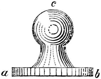
The whole is pounded on an iron table by means of a flat mullet, like that used by painters (fig. 112), whose grinding surface is a b, and c the knob for the hand. This cement is applied liquid so as to offer no resistance to the close union of the pieces, which it is intended to unite.
Fig. 112.
Cement for filling up voids, and fixing the rings in the frames.
12 parts white lead.
3 do. whiting.
1 do. minium.
4 do. boiled lintseed oil.
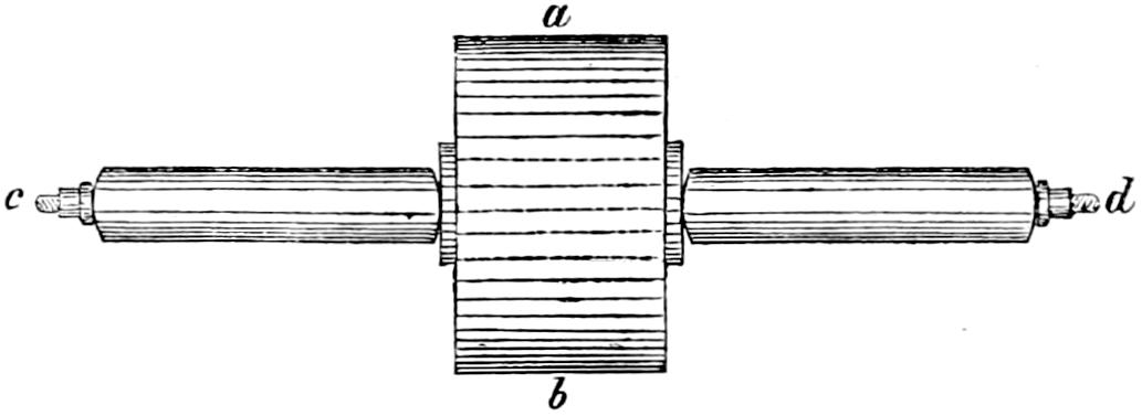
This last composition differs from the former only in the introduction of whiting, which, while like minium it has a desiccative property, gives more body to the cement and prevents the formation of cracks. The oil is also decreased in quantity, as the cement must be used in a more compact state. The trituration of this cement is performed by means of a cylindric iron roller a b, with a centre-spoke c d for the hand (fig. 113).
Fig. 113.
It is essential for the production of good cement, that the mixture of the ingredients be complete.
Prices of the various parts of the Dioptric Apparatus.
The expense of the various parts of the Dioptric apparatus is as follows: Great lens of first order, L.58 (8 of which are required); pyramidal lens and mirror, L.14, 12s. (8 of which are required); catadioptric cupola, L.480; catadioptric rings below lenses, L.360; pannel of dioptric belt for fixed light of first order, L.56 (of which 8 are required for the whole circle); apparatus of fourth order, for a fixed light, for whole horizon, L.128; apparatus of sixth order, for whole horizon, L.44. The expense of the mechanical lamp of the first order with four wicks, as made for the Scotch Lighthouses by Mr John Milne of Edinburgh, is L.30.
Diagrams illustrative of the Table, Appendix, No. IV.
Fig. 114.
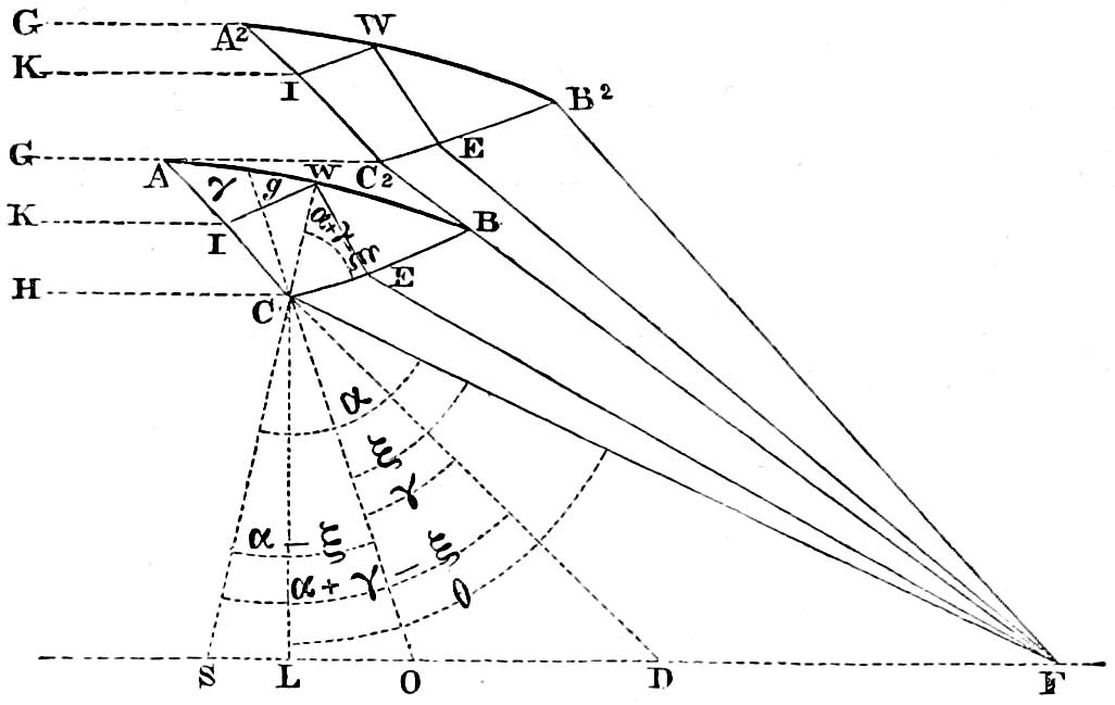
Fig. 115.
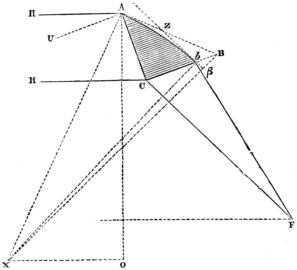
Fig. 116.
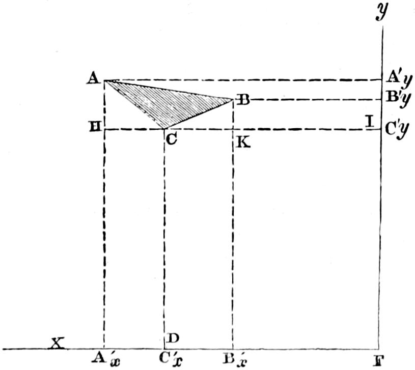
Fig. 117.
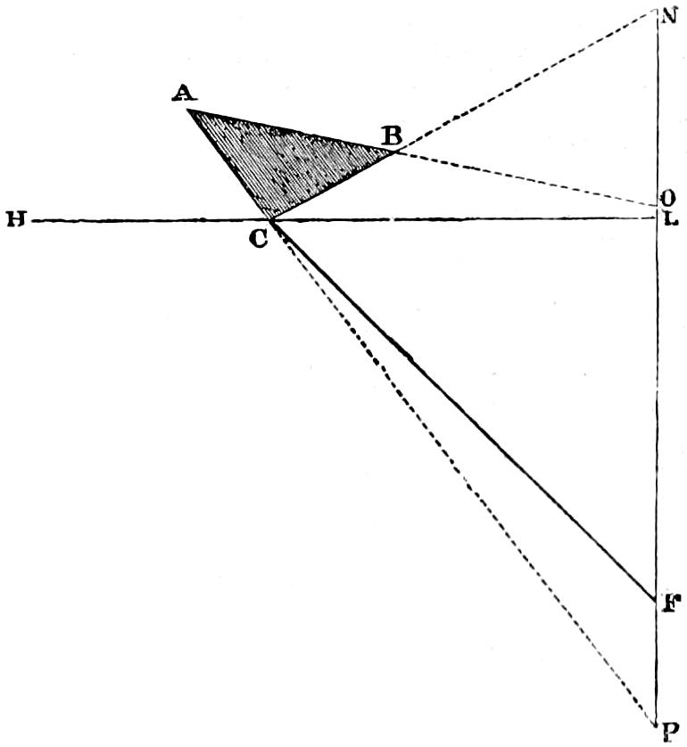
APPENDIX, No. IV. TABLE OF THE ELEMENTS OF CATADIOPTRIC ZONES SUITED FOR LIGHTS OF THE FIRST ORDER IN THE SYSTEM OF AUGUSTIN FRESNEL.
Note.—The Six co-ordinates of the Generating Triangle of each Zone in these Tables have the Focus of the Principal Lenses of the System for their origin; it being considered more convenient, in executing the necessary protractions, preparatory to the construction of the grinding apparatus, at once to refer the whole of the grinding machinery to the axis of the apparatus. To prevent the appearance of any inconsistency, however, it is proper to mention, that the radiant points of the series of Zones, do not exactly coincide with the Focus of the Lenses nor with each other; and that to avoid the parallax which the distance of the radiant points from the origin of the co-ordinates would occasion, it is necessary to make some corrections upon the linear dimensions, so as to find the line corresponding to the angles θ, ξ, and the distance Δ. In the Hyperpyral series, which stands above the flame, the Zones have the radiant point 10 millimetres above the Focus of the Lenses, and each y of this series, therefore, requires a reduction of that quantity; while the x remains unchanged. In the Hypopyral series, which stands below the flame, the Focus or radiant points of each Zone, varies its place in the flame, moving upwards as the Zone is lower, so that the line joining the Zones and the Foci, revolves as a radius vector round a point between them. In this way, the x’s remain unaltered; but the y’s will be lengthened successively by the addition of 10, 14, 19, 25, 32, and 40 millimetres. As these Tables contain the dimensions of Zones which are intended as an addition to the apparatus of Fresnel, I have adopted the metric scale, so as to render them at once applicable to the existing protractions of that system. It is only necessary to add, that the conversion of millimetres into imperial inches, is easily effected by adding the log. millimetres to the log. ̅2·59516, the sum being the log. of the equivalent of the first term in imperial inches.
θ ξ BCA, ABC, BAC, BA, BC, AC, Co-ordinates of the Apices of the Generating Triangle, in Millimetres, having the Axis of the System cut by the horizontal plane of the focus of the Annular Lenses, for its origin. (Fig. 116.) Inclination of the Sides of the Generating Triangle to the Vertical Axis of the System. (Fig. 117.) AB, Reflecting Surfaces (convex). (Fig. 115.) AC, Outer Refracting Surfaces (concave). BC, Inner Refracting Surfaces (convex). Δ,
No. of Zone. Inclination of Ray FC to the Vertical Axis of the System. Incidence of Ray FC on Side BC of Zone. Obtuse Angle of the Generating Triangle of the Zone. Angle of Generating Triangle of Zone. Angle of Generating Triangle of Zone. Reflecting Side of Zone in Millimetres being Chord of the Arc b A. Inner Refracting Side of Zone in Millimetres. Outer Refracting Side of Zone in Millimetres. Ay Ax By Bx Cy Cx Inclination of AB. Inclination of BC. Inclination of AC. Radius of Curvature in Millimetres, XA or X b. Horizontal distance of centre of curvature X from the axis of the System in Millimetres = OX. Vertical distance of centre of curvature X below the outer arris of the Zone at A in Millimetres = OA. Inclination of the Two Radii in A and B. Inclination of the Outer Radius in A to the Vertex. Radius of Curvature in Millimetres. Horizontal distance of centre of curvature from the axis of the System in Millimetres. Vertical distance of centre of curvature above the outer arris of the Zone at A in Millimetres. Inclination of the Radii in A and C. Inclination of the Outer Radius at A to the Vertex. Radius of Curvature in Millimetres. Horizontal distance of centre of curvature from the axis of the System in Millimetres. Vertical distance of centre of curvature below the outer arris of the Zone at A in Millimetres. Inclination of the Radii in C and B. Inclination of the Outer Radius in C to the Vertex. Distance of C from the Focus for the Zones, in Millimetres = FC. No. of Zone.
(Fig. 114.) (Fig. 114.) (Fig. 114.) (Fig. 114.) (Fig. 114.) (Fig. 115.) (Fig. 115.) (Fig. 115.) (Fig. 114.)
° ′ ″ ° ′ ″ ° ′ ″ ° ′ ″ ° ′ ″ ° ′ ″ ° ′ ″ ° ′ ″ ° ′ ″ ° ′ ″ ° ′ ″ ° ′ ″ ° ′ ″ ° ′ ″
HYPER- PYRAL SERIES OF ZONES. - 1 60 45 38 44 06 09 117 26 40 31 48 10 30 45 10 160·331 92·379 95·209 593·369 986·260 551·481 831·497 525·000 920·000 74 51 19 73 20 31 44 06 09 8750·19 3194·76 8466·88 1 02 59 14 38 11 4000·00 3825·31 2817·77 1 21 50 45 12 56 4000·00 2021·19 3777·07 1 19 24 15 58 47 1054·34 1
2 56 55 38 41 28 10 116 00 42 32 32 01 31 27 17 155·430 90·249 93·011 663·063 957·410 617·423 808·832 593·369 895·816 72 55 27 74 32 32 41 28 10 8253·90 3306·80 7909·94 1 04 45 16 32 11 ... 3923·65 2683·55 1 19 56 47 51 52 ... 1918·37 3797·40 1 17 34 14 48 41 1069·02 2
3 53 05 38 38 48 29 114 31 20 33 17 30 32 11 10 151·551 88·729 91·434 734·313 926·908 684·958 783·619 663·063 869·605 70 59 39 75 42 51 38 48 29 7850·30 3411·75 7446·67 1 06 22 18 27 11 ... 4015·06 2542·31 1 18 34 50 32 14 ... 1813·60 3815·77 1 16 16 13 39 01 1087·52 3
4 49 15 38 36 07 09 112 58 40 34 04 36 32 56 44 148·580 87·768 90·424 807·357 894·222 754·267 755·451 734·313 840·920 69 03 53 76 51 31 36 07 09 7527·08 3514·22 7056·39 1 07 51 20 22 11 ... 4098·54 2394·23 1 17 42 53 14 00 ... 1707·55 3831·95 1 15 26 12 30 46 1109·85 4
5 45 25 38 33 24 19 111 23 00 34 53 07 33 43 53 146·444 87·332 89·947 882·445 858·858 825·547 723·921 807·357 809·337 67 08 12 77 58 41 33 24 19 7275·23 3617·56 6730·66 1 09 12 22 17 11 ... 4173·08 2239·64 1 17 18 55 57 02 ... 1599·72 3846·04 1 15 04 11 23 47 1136·14 5
6 41 35 38 30 40 05 109 44 32 35 42 57 34 32 31 145·087 87·403 89·986 959·847 820·325 899·011 688·608 882·445 774·426 65 12 36 79 04 27 30 40 05 7082·17 3723·81 6459·63 1 10 25 24 12 11 ... 4237·70 2078·82 1 17 20 58 41 15 ... 1489·62 3858·14 1 15 08 10 17 59 1166·57 6
7 37 45 38 27 54 34 108 03 30 36 34 01 35 22 29 144·481 87·977 90·536 1039·852 778·108 974·899 649·051 959·847 735·730 63 17 03 80 08 56 27 54 34 6944·09 3835·23 6234·93 1 11 31 26 07 11 ... 4291·45 1912·18 1 17 48 61 26 32 ... 1376·71 3868·30 1 15 36 9 13 16 1201·46 7
8 33 55 38 25 07 52 106 20 06 37 26 11 36 13 43 144·609 89·060 91·604 1122·784 731·645 1053·471 604·730 1039·852 692·742 61 21 35 81 12 14 25 07 52 6857·03 3954·67 6052·36 1 12 30 28 02 11 ... 4333·30 1740·12 1 18 44 64 12 46 ... 1260·38 3876·59 1 16 32 8 09 30 1241·16 8
9 30 05 38 22 20 07 104 34 36 38 19 23 37 06 01 145·476 90·671 93·209 1209·000 680·322 1135·025 555·059 1122·784 644·900 59 26 08 82 14 29 22 20 07 6817·87 4081·70 5902·53 1 13 20 29 57 11 ... 4362·26 1563·10 1 20 06 66 59 50 ... 1139·94 3883·03 1 17 56 7 06 33 1286·15 9
10 26 15 38 19 31 25 102 47 12 39 13 27 37 59 21 147·089 92·843 95·384 1298·900 623·433 1219·892 499·354 1209·000 591·556 57 30 46 83 15 47 19 31 25 6824·46 4226·67 5795·68 1 14 05 31 52 11 ... 4377·24 1381·63 1 21 58 69 47 36 ... 1014·67 3887·66 1 19 48 6 04 19 1336·99 10
11 22 25 38 16 41 54 100 58 10 40 07 14 38 54 36 145·361 93·000 95·413 1390·290 559·378 1308·183 439·428 1288·900 531·963 55 36 30 84 16 16 16 41 54 6880·52 4385·63 5718·52 1 12 37 33 47 11 ... 4376·72 1194·94 1 22 00 72 37 06 ... 884·95 3893·00 1 19 56 5 03 46 1394·36 11
12 18 42 02 13 56 26 99 10 50 40 59 53 39 49 17 143·362 93·000 95·271 1482·755 490·169 1398·007 374·538 1390·290 467·217 53 45 43 85 14 24 13 56 26 6980·89 4558·83 5672·64 1 10 36 35 38 59 ... 4360·70 1009·41 1 21 12 75 22 58 ... 752·78 3897·32 1 19 56 4 05 38 1457·22 12
13 15 06 03 11 16 04 97 26 07 41 51 03 40 42 49 141·379 93·000 95·127 1576·048 415·991 1488·972 304·611 1482·755 397·403 51 58 53 86 10 02 11 16 04 7123·05 4747·24 5654·92 1 08 15 37 26 59 ... 4329·31 828·19 1 21 46 78 03 02 ... 618·37 3901·10 1 19 56 3 10 00 1525·43 13
° ′ ″ ° ′ ″ ° ′ ″ ° ′ ″ ° ′ ″ ° ′ ″ ° ′ ″ ° ′ ″ ° ′ ″ ° ′ ″ ° ′ ″ ° ′ ″ ° ′ ″ ° ′ ″
HYPO- PYRAL SERIES. - 1 59 49 16 43 27 36 117 05 56 31 58 37 30 55 27 159·369 92·000 94·806 593·815 985·212 550·915 831·725 525·000 920·000 74 23 03 73 38 20 43 27 36 8674·74 3243·48 8375·64 1 03 09 15 05 22 4000·00 3855·83 2785·60 1 21 28 45 51 40 4000·00 2002·52 3781·91 1 19 04 15 42 08 —— 1
2 55 48 55 40 42 01 115 35 07 32 44 43 31 40 09 158·051 92·000 94·783 682·731 981·810 634·862 831·183 610·872 920·000 72 22 10 74 53 06 40 42 01 8419·60 3456·44 8047·72 1 04 31 17 05 32 ... 3983·21 2644·16 1 21 28 48 37 15 ... 1918·55 3801·51 1 19 04 14 27 22 —— 2
3 51 48 33 37 54 32 114 00 31 33 28 16 32 27 13 156·592 92·000 94·719 779·464 978·917 726·831 830·694 704·730 920·000 70 21 45 76 05 59 37 54 32 8278·82 3685·41 7823·68 1 05 01 19 05 13 ... 4104·84 2494·82 1 21 24 51 24 46 ... 1836·22 3818·93 1 19 04 13 14 29 —— 3
4 47 51 11 35 07 32 112 23 53 34 20 23 33 15 44 155·083 92·000 94·619 885·046 974·441 827·926 830·261 807·657 920·000 68 23 16 77 16 21 35 07 32 8252·95 3941·89 7701·00 1 04 36 21 04 24 ... 4218·56 2340·02 1 21 20 54 11 48 ... 1756·33 3834·20 1 19 04 12 04 07 —— 4
5 43 59 40 32 23 06 110 46 32 35 08 23 34 05 05 153·489 92·000 94·488 1000·663 970·608 939·385 829·882 920·871 920·000 66 28 11 78 23 26 32 23 06 8335·86 4228·06 7673·05 1 03 18 23 00 10 ... 4322·95 2182·17 1 21 12 56 56 18 ... 1679·85 3847·38 1 19 04 10 57 02 —— 5
6 40 16 34 29 43 19 109 10 04 35 55 37 34 54 18 151·863 92·000 94·334 1127·665 966·771 1062·591 829·557 1045·740 920·000 64 37 37 79 26 45 29 43 19 8522·64 4549·97 7732·80 1 01 15 24 51 43 ... 4416·91 2023·99 1 21 04 59 36 09 ... 1607·39 3858·56 1 19 04 9 53 43 —— 6
APPENDIX, No. V. NOTICE TO MARINERS.—SKERRYVORE LIGHTHOUSE.
The Commissioners of the Northern Lighthouses hereby give notice, that a Lighthouse has been erected upon the Skerryvore Rock, which lies off the Island of Tyree, in the county of Argyll, the Light of which will be exhibited on the Night of the 1st February 1844, and every Night thereafter, from sunset to sunrise.
A specification of the bearings of the Lighthouse and character of the Light will be found on the next page.
And the Commissioners hereby further give notice, that by virtue of a Warrant from the Queen in Council, of date the 13th December 1843, the following Tolls will be levied for voyages in respect of which benefit will be derived from this Light, viz., from every British Vessel (the same not belonging to Her Majesty, or being navigated wholly in ballast), and for every Foreign Vessel which, by any Act of Parliament, Order in Council, Convention, or Treaty, shall be privileged to enter the Ports of the United Kingdom of Great Britain and Ireland, upon paying the same duties of tonnage as are paid by British Vessels (the same not being navigated wholly in ballast), the Toll of One Penny per Ton of the Burden of every such Vessel; and for every Foreign Vessel not so privileged, the Toll of Two Pence per Ton.
By Order of the Commissioners,
(Signed)C. Cuningham, (Signed)Alex. Cuningham,
}Joint Secs.
Edinburgh, 23d December 1843.
The following is a Specification of the Position of the Lighthouse, and the Appearance of the Light, by Mr Alan Stevenson, Engineer to the Commissioners.
The Skerryvore Rock lies off the Island of Tyree, in Lat. 56° 19′ 22″ N.; Long. 7° 6′ 32″ W.
By Compass, the Lighthouse bears from Barrahead Lighthouse S. ¹⁄₄ E., distant 33 nautic miles; from Hynish Point, in Tyree, WSW. ¹⁄₂ W., distant 10¹⁄₃ miles; from Iona Island, WNW. ³⁄₄ N., distant 20 miles; from Rhinns of Islay Lighthouse, N. ¹⁄₄ E., distant 44 miles; and from Innistrahull Lighthouse in Ireland, NE. by N., distant 53¹⁄₂ miles.
Owing to the distance to which the foul ground extends on every side of the rock on which the Lighthouse is placed, and the weight of sea which breaks on the shallow ground all round it, it is necessary to give the Light a wide berth. The better to enable seamen to judge of this, their attention is called to the prefixed Chart,[87] which exhibits the relative position of the Skerryvore Rock, and the various dangers around it. In particular, it is necessary to notice the position of those rocks which lie seaward of the Lighthouse, viz. Mackenzie’s Rock, about 3 miles W. by S. ¹⁄₄ S. from the Lighthouse; Stevenson’s, 2¹⁄₄ miles W. ¹⁄₂ N.; and Fresnel’s, which lies between these two Rocks. To the left of the prefixed Chart is a small diagram, which exhibits the position of the Skerryvore Rock in reference to the principal landmarks above noticed.
The Skerryvore Light will be known to mariners as a Revolving Light, producing a Bright Flash once every minute. The Lantern, which is open all round, is elevated 150 feet above the level of the sea. In clear weather the flashes of the Light will be seen at the distance of six leagues, and at lesser distances according to the state of the atmosphere; and to a near observer, in favourable circumstances, the Light will not wholly disappear between the flashes.
APPENDIX, No. VI. ACCOUNT OF THE EXPENSE OF ERECTING THE SKERRYVORE LIGHTHOUSE AND OF THE SUBSIDIARY WORKS.
Establishment at Hynish.
Wages of the different workmen quarrying and dressing the stones, and building the dwelling-houses, barracks, storehouses, inclosure and subdivision dykes, draining and trenching the ground, &c., at Hynish, and the wages of joiners preparing and fitting up the joiner work, £2996 7 7
Timber, pavement, bricks, ironmongery, glass, &c., &c., used in the erections, 1376 16 9 ¹⁄₂
Slater, plaster, and plumber work of the houses, 436 1 0
Paid the tenant of Hynish for a barn which was used as a barrack to accommodate the workmen when they first landed at Tyree, 13 0 0
£4822 5 4 ¹⁄₂
Note.—Although these buildings had been erected for the purposes of the works, yet the greater part of them were designed to serve as part of the permanent accommodation required at Tyree in connection with the Lighthouse Establishment, and have accordingly been so applied.
Rock Barrack, No. 1.
Cost of the barrack on the Rock, which was destroyed, including the contractor’s account for extra work, &c., £742 17 7
Lead for running up the bats and for other purposes about the barrack, 14 11 6 ¹⁄₂
A smith’s forge, bellows, anvil, and smith’s tools used at Rock in erecting the barrack, 32 19 1 ¹⁄₄
790 8 2 ³⁄₄
Rock Barrack, No. 2.
Cost of the carpenter and joiner work on the second barrack, the expense of fitting and erecting it at Greenock, the wages of four joiners and a smith, furnished by the contractor to assist in its erection at Skerryvore, including sundry other minor charges, £911 14 4
Cost of the iron-work of the barrack, 369 11 8
Lead for running up the bats and protecting the timber of cooking apartment, &c., 29 11 10
Cooking apparatus for the cook-room of barrack, sheet-iron smoke tube, cooking utensils, &c., 54 16 6
Bedding for beds of barrack, 90 9 1
Expense of upholding and making sundry small repairs on the barrack since its erection, 22 18 6 ¹⁄₂
1479 1 11 ¹⁄₂
Cost of the furniture, bedding, and other utensils required for the dwelling-houses, barracks, &c., connected with the different establishments of the works, 830 19 2
Establishment at North Bay.
Wages of the quarriers, masons, joiners, &c., quarrying stones, building the barracks, storehouses, &c., &c., and fitting up the joiner work, £378 11 9
Timber and other furnishings for the erections, the expense of making the doors and windows, including furnishings required for erecting the habitable part of Skerryvore Barrack at North Bay as a temporary accommodation for the workmen, and sundry other charges, 361 4 7
Sundry furnishings—such as utensils for provision store, smithy, &c., 13 2 5
752 18 9
Quarries at North Bay.
Cost of rails and timber for railway and timber, &c., for shipping-pier at North Bay, £131 5 1
Wages of workmen who were employed at quarries in North Bay, quarrying the lighthouse blocks, constructing the pier, railway, &c., 1752 5 3
1883 10 4
Temporary Wharf and Railway at the Skerryvore Rock.
Cost of timber used in the wharf and railway at the Skerryvore Rock, £103 18 6
Iron bats, bolts, &c., for fastening the timber, rails for railway, and sundry furnishings connected with an apparatus for blasting under water, 119 7 6
Wages of the workmen constructing the railway, fastening the timber of wharf, &c., 34 10 5
257 16 5
Excavation at Rock and Platform, &c.
Wages of the workmen excavating the foundation for the Lighthouse Tower, on the Skerryvore Rock, £609 2 3 ¹⁄₂
A portable forge, and other smith’s tools, used at the rock for this work, 21 15 10
Wages of the workmen excavating the site of a platform at the workyard in Hynish, and quarrying and dressing stones for sill of platform, £107 16 5
Cost of freestone from Garscube Quarry, Glasgow, for part of the sill of platform, 24 14 0
763 8 6 ¹⁄₂
Dressing Lighthouse Blocks.
Wages of masons, including the assistance of labourers, carters, &c., in dressing the blocks for the Lighthouse Tower at Hynish, £8589 8 7 ¹⁄₂
Timber for moulds of the various blocks, and the joiners’ wages making the moulds, 384 18 10
Timber, &c., and wages of joiners in erecting sheds for the masons, 955 4 5
9929 11 10 ¹⁄₂
Expense of victualling the workmen and others who were employed at the rock during the operation of the whole works, 1503 18 6
Implements and Tools for Masons, Smiths, &c.
Amount paid to sundry persons for the implements and tools used by the workmen in all the departments of the works, £1176 9 6 ¹⁄₂
Wages of the smiths and their hammermen keeping these tools in repair and making others, 908 16 5
2085 5 11 ¹⁄₂
Machinery for the Works at the Rock, Hynish, and North Bay.
Cost of cranes, crabs, winches, trucks, iron blocks, chains, rope-guys, &c., with sundry other furnishings connected with these articles, £1516 9 5
1 Woolwich or sling-cart, a janker for wood, and four jack-screws, 89 6 4
Large balance crane used in building the Lighthouse Tower, 533 10 0 ¹⁄₂
Hoisting beams or needles, and a pair of strong sheer-poles, used in building the Lighthouse Tower, 42 11 2
2181 16 11 ¹⁄₂
Cartage Account.
Cost of 3 large draught horses and a pony, for the use of the works, £127 9 10 ¹⁄₂
Carts and stable utensils, 65 14 2 ¹⁄₂
Harness and other furniture, and keeping them in repair, 52 2 3 ¹⁄₂
Provender for the horses for seven years, 858 14 8
1104 1 0 ¹⁄₂
Mortar Account.
Cost of the lime which was used for all the departments of the works, £331 9 8
Pozzolano which was used for the building of the Lighthouse Tower, excepting a small portion for the works of the harbour or dock, 376 16 4
Mastic, cements, and stucco, 39 6 10
Wages of labourers grinding and sifting Pozzolano at Hynish, and burning and sifting a portion of the lime, 121 18 8
Packages to contain Pozzolano, to prevent its admixture with other cargo when on board ship, 20 0 1
889 11 7
Signal Tower at Hynish.
Expense of quarrying, dressing, and building the stones, and executing the joiner work of the Signal Tower at Hynish, £370 13 2
Pavement and bricks for the interior, 32 13 1
Cast-iron floor, with lintels and sole plates for windows, and cast-iron supports for do., 110 13 4
Timber for joisting of floors, lining of walls and windows, including the glazing of them, a wooden trap, flag-pole, and other furnishings for interior, 284 9 0
Plumber work of roof, 35 9 6
A 5 feet achromatic telescope, with stand, &c., for Signal Tower, 35 10 0
Cost of a code of signals, flags, return books, and other furnishings, 11 10 6
880 18 7
Lights Account.
Expense of the apparatus required for the lights at the Pier and Signal Tower at Hynish, including fitting up, &c., £66 7 0
Cost of oil and other requisites for upholding these lights, 136 5 8
Salary of the Lightkeepers, &c., 131 11 7
334 4 3
“Skerryvore” Steamer.
First cost and complete outfit of the steamer Skerryvore, £5930 0 11
Alteration on the engines, by raising the shafts, &c., 423 5 0
Repairs on the hull and engines, on various occasions, during the progress of the works, 1057 4 2
Sailing expenses (exclusive of the cost of coals supplied when the steamer was at Hynish), and sundry other minor charges, 5538 10 11 ¹⁄₄
12,949 1 0 ¹⁄₄
“Queen” Tender.
First cost and complete outfit of the “Queen” Tender, £935 13 3
Sailing expenses and other charges, 1010 7 9
Repairs on the hull, rigging, sails, &c., 77 12 8 ¹⁄₄
2023 13 8 ¹⁄₄
Stone Lighters.
First cost and outfit of four lighters for transporting the Lighthouse blocks, &c., from Hynish to the Skerryvore Rock, £1666 15 6 ¹⁄₂
Hawsers for towing, mooring-ropes, heaving-lines, &c., used in the course of transporting the stones to the Rock, 249 1 6
Upholding the lighters in repair, and sundry other charges, 178 9 9 ¹⁄₂
Expense transporting the lighters on various occasions to different places, 58 15 10
Expense shifting and attending upon the lighters when lying at Leith, and advertising them for sale, 19 9 10 ¹⁄₂
2172 12 6 ¹⁄₂
Moorings.
Cost of the buoys for mooring the vessels belonging to the works in Hynish Bay, and at the Rock, when lying there, £240 1 3
Cast-iron mushroom anchors for mooring the buoys, 118 7 4
Wrought-iron common anchors, grapnels, &c., for mooring the vessels, warping, kedging, &c., 48 16 1
Chains and shackles for do., &c., 354 2 7
Upholding and keeping in repair the buoys, 4 17 1
766 4 4
Boats and Attendance.
Cost of 8 boats, with oars, sails, tackling, &c., £207 19 11 ¹⁄₂
Upholding these boats in repair, 28 13 9
Amount paid for the use of boats and their crews assisting to discharge cargoes from vessels previous to the pier being built, 119 6 0
355 19 8 ¹⁄₂
Amount paid the owners of hired vessels, as freights of the Lighthouse blocks from the quarries at North Bay, in Mull, to the workyard at Hynish, 1300 14 8 ¹⁄₂
Freight and Sailing Expenses.
Freights and other charges paid the owners of hired vessels, vessels, for the materials which were imported for the use of various departments of the works, exclusive of the Lighthouse blocks from North Bay, 4045 9 7 ¹⁄₂
Wages of labourers, &c., discharging the cargoes from the vessels at the Pier at Hynish, and the wages of workmen quarrying stones for ballast, and putting it on board the vessels, 933 12 10
Amount paid for travelling expenses, and other charges connected with the transport of the workmen, including the expenses of the Officers, &c., travelling on the business of the works, 1711 11 2
Cost of the coals supplied to the steamer “Skerryvore,” when plying between the Skerryvore Rock, Hynish, &c., for the household purposes of the different departments of the works, and also for the smith’s forge, 1463 0 7 ¹⁄₂
Cost of the blasting powder used for the purpose of quarrying stones, excavating rocks, &c. 375 14 2 ¹⁄₂
Lighthouse Tower.
Wages of the workmen who were engaged at Skerryvore Rock in building the Tower, and shipping the materials at Hynish for Rock, including the wages of masons, &c., assisting the other tradesmen in the respective departments of their work, after the completion of the building operations, £2381 11 7
Cost of the wainscot and other articles for the joinery of the interior of the Lighthouse; the wages of the joiners preparing the wood at Hynish, and fitting it up at the Tower, 1415 5 1
Green heart and oak for treenails, for securing the lower courses of Lighthouse Tower, 40 10 4
Plate-glass for windows and borrowed lights in partitions of Tower, 84 7 4
Lewis bats, hinges, &c., for entrance-door and shutters of Tower, and the locks and other mounting for the interior, 218 15 2
14 Copper oil-cisterns, a copper-pump, gauging-rods for do., 276 10 7
Cast-iron water-tanks and coal-boxes, for interior of Tower, 160 13 9
A large cooking apparatus for kitchen of Tower, a stove to heat the lower apartments, and cast-iron smoke-tubes for both fire-places, 117 17 7
A bell-metal railing for balcony, 341 13 1
A bell-metal ladder from rock to entrance-door of Tower, 194 13 4
A cast-iron pillar to support floor of light-room, 17 8 7
A bell-metal lightning-conductor for Tower, and fixtures, 65 13 0
Cast-iron permanent railway on the Skerryvore Rock, from the landing creek to the Tower; a cast-iron platform near the Tower, and stairs at landing creek, 493 11 8
A crane erected at the landing creek, for landing materials on the rock, 98 13 2
A copper flagstaff and ball for the top of the Lighthouse Tower, with bell-metal base, fixtures, pulleys, &c., 66 10 8
A brass force-pump, for pumping water up from tanks to kitchen of Lighthouse, 31 17 5
Premiums paid the seamen who were employed in the shipping department, in lieu of extra time, 454 2 6
Premiums paid 17 seamen who were employed in the building works at the Rock during the season of 1842, in lieu of extra time, 121 11 0
Premiums of the landing master at Rock, foreman of masons, &c., 96 12 0
Cost of the furniture, bedding, utensils, books, &c., for the Lighthouse Tower, 304 6 10
Sundry furnishings connected with the building of the Lighthouse Tower,—the wages of workmen quarrying stones at Hynish for Lighthouse Tower, previous to opening quarries at North Bay, and the wages of workmen, and furnishings for the general purposes of the works, 1386 18 5 ¹⁄₂
Cost of three models, in stucco, of different forms of the Lighthouse, 22 4 6
Cast-iron water-tanks, which were built and secured into recesses of the rock, for the supplying of the rock works,—new water-casks, and their repairs, for taking off water, 17 5 11
Feu-duty, rent of ground, assessed taxes, &c., for the establishment at Hynish, 143 6 4
8551 19 10 ¹⁄₂
Cost of the iron and steel which were used for all the departments of the works, 1299 3 5 ¹⁄₄
Lightroom and Apparatus.
Cost of the lantern of cast-iron, with facings of bell-metal, including the cleaning and trimming paths, and bell-metal ladder outside of lantern, and the wages of the contractor’s workmen fitting them up at Skerryvore, £863 13 6
Plate-glass for the lantern, 268 4 6
Copper dome of lantern, including the internal frame of do., drip-pan, copper steps, handles, air-tubes, rain-water pipes, a platform outside of dome for cleaning the vents, with the wages of the contractor’s workmen fitting them up at Skerryvore, 348 16 9
Machinery of the revolving apparatus, and brass case for do. complete; three machines for pumping the oil for supplying the burner; the expense of the lamps, fountains, &c.; and bell-metal frames for annular lenses, zones, pyramidal lenses, &c., with the wages of the contractor’s workmen fitting up the above apparatus at Skerryvore, 1244 10 6 ¹⁄₂
The charge of Mr François of Paris furnishing eight annular lenses, and two spare do., with eight catadioptric frames of the first order for lower part, and eight pyramidal lenses, with mirrors, for upper part, £762 0 0
Expense of transporting the whole apparatus to Leith, 79 7 10
841 7 10
Cost of two bells, and one spare do., used during foggy weather, £107 6 3
Shafting for do.; bevel wheels, levers, hammers, &c., connecting with the machinery of apparatus, 63 14 11 ¹⁄₂
171 1 2 ¹⁄₂
Eighteen screens for lantern, cased with iron, and brass mounted, with rollers, &c., and the time of workmen fitting them up at Skerryvore, 48 7 6
Air watch-bells from lightroom to bedrooms and kitchen, time of workmen fitting them up at Skerryvore, and furnishings for the complete working of do., 34 13 0
Brass medallion heads and copper tubes for ventilation of lightroom, 8 9 6
Wood and workmanship making models of the catadioptric zones to a full size, and a brass model of frame for zones to a small scale, 22 1 2
3851 5 6
Salaries, Agencies, and Office Expenses.
Salaries of the Engineer, Surveyor, Clerk, and Store-keeper, including expenses of the survey of the rocks and adjoining Islands, £3262 10 5
Agency of the Agent at Aberdeen, who made the monthly payments to the workmen’s relatives, and for some time superintending the making of tools; and the agency of the Lighthouse Agent at Greenock transacting business for the works, 294 13 11
Iron safe, &c., books, and other stationery for the various departments of the works, 99 10 10
3656 15 2
Petty disbursements and miscellaneous expenses, made on account of the general purposes of the works, 308 7 9
Lightkeepers’ Houses.
Wages of workmen, quarrying, dressing, and building the stones of houses at Hynish for light-keepers, building the brick partitions and lining of walls, and the wages of joiners executing the joiner-work, £1893 6 2
Timber and other articles used in the joinery of the houses, 462 19 9
Plumber-work of roof, including the expense of bringing the water into the houses, &c., 963 18 6
Bricks for partitions, lining of external walls, &c., 73 10 0
Pavement for floors, water-cisterns, &c., 51 16 0
Workmanship, executing the plaster-work (the lime being charged in a special account for this article), 38 12 11
Glass for glazing the windows and fan-lights, 20 12 3
Locks, hinges, and other mounting for the doors and windows, 101 11 11
Cans for the chimney heads, 9 16 6
Furniture, bedding, utensils, &c., supplied for these houses, 299 0 4
3915 4 4
Pier at Hynish.
Wages of masons, quarriers, carters, labourers, &c., quarrying, dressing, and building the stones of a pier at Hynish for the landing and shipping of materials, £2300 17 1 ¹⁄₂
Iron rails for the works of building the pier, 53 10 1
Timbers for fenders of pier, and other purposes connected with the building of it, 130 19 4
Cost of a pont for building the pier, 106 8 11
2591 15 5 ¹⁄₂
Dock or Harbour for Tender.
Wages of workmen, quarrying, dressing, and building stones to form a talus wall and parapet along the south side and round the point of the pier at Hynish; raising the pier one course; excavating rock in the interior of the harbour or dock and along the point of pier; quarrying, dressing, and building the stones of boom-heads and walls of dock; excavating reservoir and forming embankment of do, for scouring sand, &c., from the dock; forming the feeders to reservoir, and the tail-race from reservoir to dock, refreshments to workmen during night and tide works, &c., £6676 10 6
Timber for double set of boom-gates of dock, copper for sheathing their ends, and mounting for booms, 101 2 6
Timber used in constructing coffer-dams, and for the general purposes of the harbour works, 135 18 0
Cost of two sluices, and of the machinery, &c., complete for working them, 81 14 0
Two cast-iron ladders for sides of pier and dock, 13 1 9
Cost of sea-boots, &c., and keeping them in repair, which were used by the workmen at tide works, 26 12 0
Cost of silt-pumps, and furnishings of leather, &c., for making others, and keeping them in repair, 9 10 0
Compensation paid the tenant of the farm of Hynish, for liberty to cut drains for a supply of water for a reservoir, 5 0 0
Two signal lamps, two torches, turpentine, &c., for signalizing when the tender enters the dock at night, 5 14 8
7055 3 5
Total, £89,817 6 11
Deductions—
Price of steamer “Skerryvore,” sold, £1616 0 6
Do. of sloop “Queen,” sold, 200 0 0
Do. of 4 Stone Lighters, sold, 225 0 0
Do. of Horses and Carts, sold, 60 0 0
Implements sold or afterwards used at other works of the Board, 738 8 10
2839 9 4
£86,977 17 7
APPENDIX, No. VII. EXCERPTS FROM AN ACCOUNT OF EXPERIMENTS UPON THE FORCE OF THE WAVES OF THE ATLANTIC AND GERMAN OCEANS. By Thomas Stevenson, F.R.S.E., Civil-Engineer, Edinburgh. (From the Transactions of the Royal Society of Edinburgh, Vol. XVI.)
The letters (see Plate IV.) D E F D represent a cast-iron cylinder, which is firmly bolted at the projecting flanges G to the rock where the experiments are wanted. This cylinder has a flange at D D. L L is a door, which is opened when the observation is to be read off. A A is of iron, and forms a circular plate or disc, on which the sea impinges. Fastened to the disc are four guide-rods B B B B. These rods pass through a circular plate C C (which is screwed down to the flange D D), and also through holes in the bottom E F. Within the cylinder there is attached to the plate C C a powerful steel spring, to the other or free end of which is fastened the small circular plate K K, which again is secured to the guide-rods B B B B. There are also rings of leather T T, that slide on the guide-rods, and serve as indices for registering how far the rods are pushed through the holes in the bottom; or, in other words, how much the spring has been drawn out or lengthened by the force of the sea acting upon the plate or disc A A. The object of having four leathern rings, where one might have answered the purpose, was merely that they might serve as a check upon each other; and so perfectly did they answer the purpose intended, that in every instance they were found equidistant from the bottom of the cylinder; proving thereby, that after the recoil of the spring, they had all kept their places. The guide-rods are graduated, so as to enable the observer to note exactly the quantity that the spring has yielded.
This instrument, which may, perhaps, be not improperly termed a Marine Dynamometer, is, therefore, a self-registering apparatus which indicates the maximum force of the waves. In the graduation of the instrument, the power of the spring is ascertained by carefully loading the disc with weights, so that when the quantity that the spring has yielded by the action of the sea is known, the pressure due to the area of the disc exposed is known also. The discs employed were from 3 to 9 inches diameter, but generally 6 inches, and the powers of the springs varied from 10 lb. to about 50 lb. for every ¹⁄₈ inch of elongation. Their respective effects were afterwards reduced to a value per square foot. The instrument was generally placed so as to be immersed at about three-fourths tide, and in such situations as would afford a considerable depth of water. It is not desirable to have the instrument placed at a much lower level, as it has not unfrequently happened during a gale, that for days together no one could approach it to read off the result and readjust the indices to zero. It must, however, at the same time be remarked, that it is in most situations almost impossible to receive the force unimpaired, as the waves are more or less broken by hidden rocks or shoal ground before they reach the instrument.
In connection with the apparatus above described, a graduated pole was erected on an outlying sunken rock, for the purpose of ascertaining the height of the waves; but the observations were not of so satisfactory a nature as could have been desired, and the poles soon worked loose from their attachments, and disappeared.
With the instrument which has been explained, I entered upon the following train of observations:—
In 1842 several observations were made on the waves of the Irish Sea at the island of Little Ross, lying off the Bay of Kirkcudbright. Since April 1843 till now, continued observations have been made on the Atlantic at the Skerryvore and neighbouring rocks lying off the island of Tyree, Argyllshire; and in 1844 a series of observations was begun on the German Ocean at the Bell Rock. It will be seen, that in selecting these localities a varied exposure has been embraced, comprising the comparatively sheltered Irish Sea, the more exposed eastern shore of Scotland, and the wild Rocks of Skerryvore, which are open to the full fury of the Atlantic, the far distant shores of North America being the nearest land on the west.
Referring for more full information to the tables of experiments which are given at the end of this paper, it will be sufficient in this place to state generally the following as the results obtained.
In the Atlantic Ocean, according to the observations made at the Skerryvore rocks, the average of results for five of the summer months during the years 1843 and 1844, is 611 lb. per square foot. The average results for six of the winter months (1843 and 1844), is 2086 lb. per square foot, or thrice as great as in the summer months.
The greatest result yet obtained at Skerryvore was during the heavy westerly gale of 29th March 1845, when a pressure of 6083 lb. per square foot was registered. The next highest is 5323 lb.
In the German Ocean, according to the observations made at the Bell Rock, the greatest result yet obtained is 3013 lb. per square foot.
It thus appears, that the greatest effect of the sea, which has been observed, is that of the Atlantic at Skerryvore, which is nearly equal to three tons per square foot.
These experiments, amounting to 267 in number, and on the Atlantic alone, extending over 23 months continuously, are not intended to prove anything farther than the simple fact, that the sea has been known to exert a force equivalent to a pressure of three tons per square foot, however much more.
It is proper, however, to observe, that there may be some objection to referring the action of the sea to a statical value. Although the instrument might perhaps be made capable of giving a dynamical result, it was considered unnecessary, in these preliminary experiments, to do anything more than represent the maximum pressure registered by the spring, because the effects of the waves may, from supposing them to have continuity of action, be perhaps regarded as similar to a statical pressure, rather than to the impact of a hard body. The near coincidence, or indeed almost perfect agreement of the results of the experiments made with different instruments, goes far to shew that the waves act in very much the same manner as a pressure, although both pressure and impact must obviously enter into their effect. In the experiments, begun February 1844, and given at the end of the paper, the three instruments had not only different areas of discs, but very different powers of springs, and yet the results were almost identical. Now, the same force, supposing the waves to act like the impact of a hard body, would, in the Marine Dynamometer, have assumed very different statical values, according to the spaces in which that force was expended or developed; so that with the same force of impact, the indication of a weak spring would be less than that of a stronger.
In future experiments it may be interesting, however, to test the springs dynamically, by means of the impact of a heavy body dropped from a given height upon the plate or disc of the instrument. In some experiments lately made in this way, by dropping a cannon-ball upon the disc, it appeared, that, within the limits of the experiments, there was for each individual spring a ratio between the value registered by the leathern index and the calculated momentum of the impinging body. These ratios were, of course, found to vary in springs of different power, and to be constant only for springs of the same power. Did the waves, therefore, act by a sudden finite impact, like the cannon-ball employed in this instance, we could scarcely have found such harmony between the results of instruments with different springs, as the experiments alluded to afford. At the same time, the result cannot, perhaps, be in strictness considered correct; but, from the elongation of the spring being very small, the results may be regarded as practically correct,—the more so when we find so remarkable a coincidence of results as that alluded to.
Experiments.—With reference to the following experiments I have only to observe, that those which were made at Little Ross, upon the Irish Sea, cannot, from the unusual fineness of the weather at the time, be regarded as affording a true value of the effects of a hard gale in these seas. Of the others it is to be noticed, that where two or three instruments were for some time employed as a check upon each other, and only one or two readings are given, the want has occurred either from the instruments being under repair, or being difficult of access in stormy weather, or during neap tides. It often happened also, in consequence of the springs proving too weak, when new ones had to be made, or the area of the disc reduced. Registers of the state of the weather, apparent height of spray, &c., were generally kept; but it was not considered necessary to complicate the Tables by inserting these, excepting in one or two instances.
Dates. lbs. to a Square Foot.
Observations at Little Ross.
1842.
April 25 15
28 51
June 1 36
4 81·5
20 86·5
24 840·0
25 458·0
July 25 380·0
Aug. 2 570·0
5 665·0
6 380·0
9 380·0
The Observations at the Skerryvore Rock, and the neighbouring Island of Tyree, distant 13 miles from the Skerryvore, are as follows:—
1843.
April 24 455
25 707
May 7 243
11 182
12 243
16 364
20 - 495
476
June 3 182
4 519
7 428
8 855
9 173
July 2 476
3 - 723
866
30 433
Aug. 9 346
22 723
30 389
Sept. 5 866
21 952
Oct. 5 1535
6 1606
Nov. 18 1711
19 1497
27 1497
29 2353
Dec. 5 2674
8 - 3421
At least
14 2460
26 1947
In January, two instruments were placed beside each other, but not set parallel. These instruments had springs of different power, the one being about double that of the other, and one had a disc of 3 inches diameter, the other 6 inches.
1844.
Jan. 6 962
928
7 2353
357
9 1925
1000
10 826
1000
Both instruments set parallel.
16 424
427
Another instrument was placed beside them, but the two marked thus* were found to be too weak, as the leathers were found flattened, and one of the instruments was broken, and was not repaired till the 15th February.
28 3422 *
2285 *
3313
Feb. 2 429
457
3 429
457
13 214
228
15 321
280
321
16 428
402
343
24 1284
1364
685
26 2032
2068
399
27 321
321
342
March 4 3316
3369
3427
7 1069
963
913
10 1925
1925
1713
11 535
481
456
12 3316
4011
2970
13 1142
1283
1283
April 10 457
428
481
11 800
12 343
321
14 571
535
16 571
642
481
17 800
856
862
18 571
481
19 800
535
481
22 913
482
962
24 1942
1604
1370
25 1283
343
321
27 457
481
- Night 800
tide
642
30 229
241
May 15 343
14 481
June 6 571
15 1828
July 11 1028
13 457
18 914
23 1532
25 571
26 971
27 457
28 1142
29 286
30 914
31 1028
Aug. 1 571
7 914
13 914
14 914
21 800
30 1713
Sept. 12 1028
14 914
20 457
23 1142
25 685
30 1599
Oct. 2 2399
3 1485
4 1828
11 3427 [88]
14 1599
19 1599
20 2513
22 800
24 1827
28 1485
29 457
Nov. 2 1942
10 1028
14 1257
15 2056
16 2056
22 2627
23 3427
27 3199
28 4112
Dec. 7 1369
9 2738
10 1825
13 1925
14 1027
15 1764
A more exposed point of the Skerryvore Rock was at this time chosen for experiment; and with the view of ascertaining the effect of the waves at different heights upon the rock, two instruments were fixed, the one (No. I.) several feet lower, and about 40 feet seaward of the other (No. II.). It was observed, that about half-flood the force of the waves was a good deal expended before they reached the place where No. I. was placed, from there being so little water on the rocks outside; whereas when the tide was higher, the waves were, from the greater depth of water, not so much broken when they reached No. II. The results of the Marine Dynamometer shew generally about twice the force at No. II. as at No. I.; a result which shews how important it would be to ascertain the relative forces of the waves at different levels upon our breakwaters and other seaworks.
Date. Remarks. No. of Instru- ment. Pressure in lbs. per Square Foot.
1845.
Jan. 7 Heavy sea. I. 1714
... II. 4182
12 Very heavy swell. I. 2856
... II. 5032
16 Heavy ground swell. I. 2856
... II. 4752
22 A good deal of sea. I. 2856
... II. 5323
28 Heavy ground swell. I. 2627
... II. 4562
Feb. 5 Fresh gales. I. 856
... II. 3042
21 ... I. 1827
... II. 3422
24 Fresh breezes. I. 1256
... II. 3802
March 9 Ground swell. I. 1256
Waves supposed about 10 feet high. II. 3041
11 Short sea. I. 1028
24 Heavy sea. I. 2281
Waves supposed about 20 feet high. II. 4562
26 Swell. I. 1256
Waves about 6 feet high. II. 3041
29 Strong gale, with heavy sea, the highest waves supposed 20 feet high, and the spray rose about 70 feet. I. 2856
... II. 6083
Register of Observations on the force of the Sea, made at the Bell Rock, German Ocean.
Dates. lbs. to a Square Foot.
1844.
Sept. 15 853
20 2260
Oct. 9 3013
... 2562
26 1142
27 958
Nov. 12 1680
13 1920
Dec. 13 1560
26 1439
1845.
Jan. 7 1559
10 1439
11 1439
15 1559
25 959
26 719
27 1199
30 2879
31 1559
Feb. 6 2999
24 1199
25 959
27 839
28 1319
March 4 959
7 1079
11 1919
20 2519
21 2759
24 1319
25 959
28 599
30 1079
APPENDIX, No. VIII. LIST OF NORTHERN LIGHTHOUSES, BEACONS AND BUOYS. FOR 1848.
Name of Light. Situation of Light. Number of Lights. Appearance of Light. Distance visible in Nautic Miles. Points of Compass within which Light is Visible. Height of Lantern in feet above High-water Spring Tides. North Latitude. West Longitude. Date of first Exhibition.
INCHKEITH Highest Land on the Island of Inchkeith, in Fifeshire One Revolving, and appearing in its brightest state once every minute 18 All round the Compass 220 56° 2′ 3° 8′ 1804
ISLE OF MAY Highest Land on Isle of May, in Fifeshire One Fixed 21 All round the Compass 240 56° 11′ 2° 33′ 1816
DO. LEADING LIGHT Placed about 130 feet below the High Light, and to the NE. by N. of it One Fixed 15 When seen in ONE line with the High Light, these two Lights bear NE. by N. ¹⁄₄ N., and SW. by S. ¹⁄₄ S., and in this line lead about half a mile to the Eastward of the North Carr Rock. The Lights must on no account be opened to the Westward 110 1844
BELL ROCK Bell Rock, a sunk reef, 11³⁄₄ miles S. by E. ¹⁄₃ E. off Arbroath, in Forfarshire One Revolving, and shewing alternately a red and white light every 2 minutes 14 All round the Compass 90 56° 26′ 2° 23′ 1811
GIRDLENESS Girdleness, Kincardineshire Two Fixed Lights, one above the other 19 & 16 From NNE. to WSW. ¹⁄₂ W. Easterly and Southerly 185 & 115 57° 8′ 2° 3′ 1833
BUCHANNESS Buchanness, Aberdeenshire One Flashing once every 5 seconds 16 From N. by E. to SW. by W. Easterly 130 57° 28′ 1° 46′ 1827
KINNAIRDHEAD Kinnairdhead, Aberdeenshire One Fixed 15 From WNW. to SE. Northerly 120 57° 42′ 2° 0′ 1787
COVESEA SKERRIES Craighead, Morayshire One Revolving, and appearing in its brightest state once every minute. From W. by N. ¹⁄₄ N. to SE. by E. ¹⁄₄ E. the light is of the natural appearance; but from SE. by E. ¹⁄₄ E. to SE. ¹⁄₄ S. it is coloured RED 18 From W. by N. ¹⁄₄ N. to SE. ¹⁄₄ S. Northerly 160 57° 43′ 3° 20′ 1846
CHANONRY POINT Chanonry Point, Ross-shire One Fixed 11 From W. ¹⁄₂ N. to N. by E. Southerly 40 57° 35′ 4° 5′ 1846
CROMARTY POINT Cromartyshire One Fixed and red 9 From WNW. to SE. by E. ¹⁄₄ S. Northerly 50 57° 41′ 4° 2′ 1846
TARBETNESS Tarbetness, Cromartyshire One Intermittent, suddenly bursting into view, and continuing in sight 2¹⁄₂ min., then suddenly eclipsed for half a minute. But within the Moray Frith, in Southerly and South-westerly directions from Tarbetness, the light does not intermit, but is permanently visible 18 From SW. ¹⁄₂ W. to W. ¹⁄₂ N. Easterly 175 57° 51′ 8° 48′ 1830
NOSSHEAD Nosshead, Caithness-shire (building)
DUNNETHEAD Dunnethead, most northern point of the Mainland of Scotland, Caithness-shire One Fixed 23 From SE. ¹⁄₂ E. to W. Northerly 346 58° 40′ 3° 21′ 1831
PENTLAND SKERRIES Pentland Skerries Island, Orkney Two Fixed, and 100 feet apart 16 & 18 All round the Compass 140 & 170 58° 41′ 2° 55′ 1794
START POINT Start Point, Sanday Island, the most eastern point of Orkney One Revolving, and appearing in its brightest state once every minute 15 All round the Compass 100 59° 17′ 2° 23′ 1806
SUMBURGH-HEAD The most southern Headland of Zetland One Fixed 22 From NE. by E. ¹⁄₄ E. to NW. by N. ¹⁄₄ N. Southerly 300 59° 51′ 1° 16′ 1821
CAPE WRATH Cape Wrath, north-western Headland of Sutherlandshire One Revolving, and shewing alternately a red and white light every 2 minutes 25 From SE. ¹⁄₂ E. to SW. by W. Northerly 400 58° 37′ 5° 0′ 1828
ISLAND GLASS Island Glass, one of the Harris Isles, Inverness-shire One Fixed 16 From W. by S. to ENE. ¹⁄₂ E. Southerly 130 57° 52′ 6° 33′ 1789
BARRAHEAD Highest land on Bernera Island, Inverness-shire One Intermittent, suddenly bursting into view, and continuing in sight 2¹⁄₂ min., then suddenly eclipsed for half a minute 32 From N. by E. to ENE. Westerly and Southerly 680 56° 48′ 7° 38′ 1833
ARDNAMURCHAN Ardnamurchan Point, Argyleshire (building)
LISMORE Mousedale, small Island off Lismore, Argyleshire One Fixed 15 From E. to NE. by E. ¹⁄₄ E. Westerly 103 56° 30′ 5° 38′ 1833
SKERRYVORE[89] Skerryvore Reef, 12 miles WSW. ¹⁄₂ W. from Tyree Island, with foul ground all round it One Revolving, and appearing at its brightest once every minute 18 All round the Compass 150 56° 19′ 7° 7′ 1844
RHINS OF ISLAY Oversay, small Island off Islay, Argyleshire One Flashing once every 5 seconds 17 From NNE. to SE. Southerly 150 55° 41′ 6° 29′ 1825
MULL OF KINTYRE South-western Headland of Argyleshire One Fixed 22 From NNE. ¹⁄₂ E. to S. by W. ¹⁄₄ W. Southerly 297 55° 1′ 5° 49′ 1787
PLADDA Pladda Isle, off south-east point of Arran, county of Bute Two Fixed, the one above the other 13 & 16 From NW. by W. to NE. by E. Southerly 77 & 130 55° 26′ 5° 7′ 1790
CORSEWALL Western side of entrance to Loch Ryan, in Wigtonshire One Revolving, and shewing alternately a red and white light every 2 minutes 15 From NE. by E. to SW. Northerly 112 55° 1′ 5° 9′ 1817
LOCH RYAN Cairn Ryan Point, within Loch Ryan, Wigtonshire One Fixed 10 From S. by W. ¹⁄₈ W. to N. ⁷⁄₈ E. Westerly 30 54° 58′ 5° 2′ 1847
MULL OF GALLOWAY Southern extremity of the Mainland of Scotland, Wigtonshire One Intermittent, suddenly bursting into view, and continuing in sight 2¹⁄₂ min., then suddenly eclipsed for half a minute 23 From NE. to NW. ¹⁄₂ W. Southerly 325 54° 38′ 4° 51′ 1830
LITTLE ROSS Little Ross Island, Kirkcudbrightshire One Flashing once every 5 seconds 18 From N. by E. to NW. by W. Southerly 175 54° 46′ 4° 5′ 1843
POINT OF AYRE Northern extremity of Isle of Man One Revolving, and shewing alternately a red and white light every 2 minutes 15 From S. by W. to W. by N. Northerly 106 54° 25′ 4° 22′ 1818
CALF OF MAN West side Calf Island, at the southern extremity of Isle of Man Two Revolving, and shewing white lights every 2 minutes 22 & 24 From NE. ¹⁄₃ to SW. W. Southerly 275 & 368 54° 3′ 4° 49′ 1818
BEACONS AND BUOYS. FRITH OF FORTH DISTRICT.
Name of Station. Description of Mark. Depth at Low Water of Spring Tides. Bearings of Marks and of Lines of Intersection Meeting at the Station.
MIDDLE BANK, WEST END, BUOY. 6 Feet Buoy, Red. 3¹⁄₂ Feet. Alloa Tower in line with the Centre of Clackmannan Pier—Bearing N. by E.
Clackmannan Church Spire in line with High Chimney-Stack of Park-Farm House—Bearing NE. ¹⁄₂ E.
Middle Bank Buoy, East End—Bearing SE. by S.
MIDDLE BANK, EAST END, BUOY. 6 Feet Buoy, Red. 4 Feet. Tullyallan House in line with Tullyallan Old Church Spire, in ruins—Bearing ESE. ¹⁄₂ S.
Remarkable Clump of Trees on distant high land in line with Airth Church Spire—Bearing W. by N. ¹⁄₂ N.
Buoy off Inch Brake Rock—Bearing S. by E.
INCH BRAKE BUOY. 6 Feet Buoy, Black. 5 Feet. Flagstaff on the Ferry Pier, Kincardine, clear outside of Kincardine Stone Pier—Bearing N. by E.
Alloa Church Spire in line with South Corner of Kennet Pans Distillery Garden Wall—Bearing N. by W.
Long Annat Buoy—Bearing SSE. ¹⁄₂ E.
LONG ANNAT 6 Feet Buoy, 9 Feet. Sands House, West Wing, in line with West Face of Annat Quarry—Bearing NNE. ¹⁄₂ E.
Binns Monument in line with the Middle of Bo’ness Pier—Bearing SE. by S.
Hen and Chicken’s Buoy—Bearing SE. by E. ¹⁄₄ S.
HEN AND CHICKEN’S BUOY. 6 Feet Buoy, Black. 12 Feet. The East Wing of Culross Abbey in line with Eastmost House in Culross Village—Bearing NNE. ¹⁄₂ E.
Airth Castle, in line with High-Water Mark on Long Annat Point—Bearing NW. ¹⁄₄ W.
Buoy on East End of Dods’ Bank—Bearing SSE. ¹⁄₂ E.
DODS’ BANK BUOY. 7 Feet Buoy, Red. 15 Feet. Berry-Law Trees in line with the Chimney-Stack of Bunyan’s Farm—Bearing E. by N.
Chimney Stack of the Snub Coal Pit (the first Stack West of Kinneil New Iron Works), in line with the West Pier Wall of Bo’ness—Bearing WSW. ³⁄₄ W.
Comary House, East Wing, in line with the West Wing of the Factor’s House—Bearing N. by E. ³⁄₄ E.
Valleyfield House, a little East of the Eastern House on Preston Island, about half-way between the house and where the Island dries at half-tide—Bearing N. by E. ¹⁄₄ E.
The Buoy of Hen and Chicken’s Rock—Bearing NNW. ¹⁄₂ W.
BEAMER BEACON. Painted Black, with Spherical Ball at top. Rock Dry at Low Water. Bo’ness Pier—Bearing NW. by W.
Charleston Pier, Outer End—Bearing NW. by N.
South-West Extremity of the Point at North Queensferry—Bearing ESE. ¹⁄₄ E.
The Halls, or principal South Queensferry Pier—Bearing SSE. ¹⁄₄ E.
DRUM SAND EAST BUOY. 7 Feet Buoy, Red. 12 Feet. Newbigging House in line with East Edge of Carcraig Rock—Bearing NE. ¹⁄₂ E.
Oxscare Beacon—Bearing E. ³⁄₄ N.
Inchkeith Lighthouse—Bearing ESE. ¹⁄₂ E.
Highest Point of Arthur’s Seat in line with Nelson’s Monument—Bearing S. by E. ³⁄₄ E.
DRUM SAND WEST BUOY. 8 Feet Buoy, Red, with Fenders. 3¹⁄₄ Fathoms. South Point of Inchkeith in line with Centre of Opening of Mickery Stone—Bearing ESE. ¹⁄₄ E.
Inchkeith Lighthouse—Bearing ESE. ¹⁄₂ E.
Fordel House in line with Centre of Donibristle House—Bearing N. ¹⁄₄ E.
Chimney-Stack of Castle Landhill Farm-House in line with End of Lazarett Pier—Bearing NW. ³⁄₈ N.
OXSCARE BEACON. Painted Red, with Flat Cone at top. Rock Dry at Low Water. South Point of Carlin’s Nose—Bearing W. ³⁄₄ N.
Burntisland Pier—Bearing ENE.
Extremity of Kinghornness—Bearing E. ¹⁄₂ N.
Inchkeith Lighthouse—Bearing ESE. ¹⁄₄ E.
Martello Tower—Bearing SSE. ³⁄₄ E.
Granton Pier—Bearing S. by E. ¹⁄₄ E.
WEST GUNNET BUOY. 8 Feet Buoy, White. 3³⁄₄ Fathoms. Nelson’s Monument just clear East of North Leith Church Spire—Bearing SSW.
North Berwick Law in line with North End of Long Craig—Bearing ESE. ¹⁄₄ E.
Clump of Trees East of Grange House in line with Burntisland Church Spire—Bearing N. ¹⁄₂ W.
Inchkeith Lighthouse—Bearing E. ¹⁄₂ S.
EAST GUNNET BUOY. 8 Feet Buoy, White. 3¹⁄₂ Fathoms. Notch at the foot of East Brow of the Pentland Hills in line with North Leith Church Spire—Bearing SSW. ³⁄₄ W.
Carlin’s Nose clear of the North Side of Mickery Stone—Bearing WNW. ³⁄₄ W.
Kinghorn New Free Church in line with Kinghornness—Bearing NE. by N.
Inchkeith Lighthouse—Bearing E.
PALLAS BUOY. 7 Feet Buoy, Striped White and Black horizontally. 3¹⁄₂ Fathoms. Kinghorn Free Church in line with Swan’s Factory—Bearing N. by E. ³⁄₄ E.
North Brow of Inchkeith in line with the Centre of Silly Carr Rock—Bearing ENE. ¹⁄₄ N.
Assembly Hall Spire, Edinburgh, in line with Martello Tower—Bearing SW. ³⁄₄ S.
Inchkeith Lighthouse—Bearing ENE. ³⁄₄ E.
HERWIT BUOY. 8 Feet Buoy, Black. 4³⁄₄ Fathoms. East Brow of Pentland Hills, touching West Brow of Arthur’s Seat (half way up)—Bearing SW. ¹⁄₂ W.
East Stables (Red-tiled House) of Pettycur in line with East Brow of Inchkeith—Bearing N. by W.
Inchkeith Lighthouse—Bearing N. by W. ¹⁄₂ W.
CRAIG WAUGH 8 Feet Buoy, 4 Fathoms. Pettycur Pier in line with Eastern Brow of Inchkeith—Bearing N. by W. ¹⁄₂ W.
Assembly Hall Spire just clear, West of Nelson’s Monument—Bearing W. ³⁄₄ S.
Inchkeith Lighthouse—Bearing N. by W. ³⁄₄ W.
NORTH CRAIG MAST BUOY. 12 Feet Mast Buoy, Chequered Red and White. 3¹⁄₄ Fathoms. Nelson’s Monument in line with West Wing of Leith Baths—Bearing WSW. ¹⁄₄ W.
Summit of East Lomond Hill in line with Big House Trees—Bearing N. ¹⁄₂ E.
Carlin’s Nose in line with Centre of Mickery Stone—Bearing WNW.
WEST ROCK-HEAD, OFF DYSART, BUOY. 6 Feet Buoy, Red. 3¹⁄₄ Fathoms. Dysart Coal-Pit Chimney-Stack in line with Middle of Gable of Pan Hall House—Bearing N. ¹⁄₄ E.
North End of Portbrae Church, Kirkcaldy, just clear of the End of Kirkcaldy Pier—Bearing WNW. ³⁄₄ W.
Inchkeith Lighthouse—Bearing SW. by S.
N.B.—The highest part of the Rock bearing N. ¹⁄₄ E. distant about one-half cable’s length from Buoy.
EAST ROCK-HEAD, OFF DYSART, BUOY. 6 Feet Buoy, Black. 3¹⁄₂ Fathoms. Wemyss Old Castle in line with Southern Houses of East Wemyss—Bearing NE. by E. ¹⁄₄ E.
East Wing of Dysart Church in line with Town-House Steeple—Bearing NNW. ³⁄₄ W.
Buoy on West Rock-Head—Bearing W. by N. ¹⁄₄ N.
Inchkeith Lighthouse—Bearing SW. ¹⁄₂ S.
N.B.—The highest part of Rock, bearing NW. ¹⁄₄ W., distant about two cables’ lengths.
EAST VOWS ROCK, BEACON, OFF ELIE. Pyramid of Iron Pillars, with open Cylindric Cage on top, painted Red. Rock Dry at Low Water. Ruins on Chapelness—Bearing N. ³⁄₄ E.
North End of Elie Pier—Bearing E. ³⁄₄ N.
Extremity of Elieness—Bearing E. by S. ¹⁄₂ S.
Isle of May Lighthouse—Bearing ESE. ¹⁄₄ S.
West Vows Rock—Bearing WNW. ¹⁄₂ N. distant ¹⁄₂ mile.
Buoy on Thill Rock—Bearing ESE. ¹⁄₈ S. distant two cables’ lengths.
THILL ROCK BUOY. 7 Feet Buoy, Black. 3³⁄₄ Fathoms. West End of Millhouse Cottage in line with North End of Elie Pier—Bearing NE.
Pettie Law in line with West Chimney-Stack of David Ovenstone’s House—Bearing N. ³⁄₈ W.
Ruin on Chapelness—Bearing NNW. ¹⁄₂ W.
Beacon on East Vows Rock—Bearing WNW. ¹⁄₈ N.
N.B.—The Buoy lies about 35 fathoms to the SSE. of the highest part of the Rock.
SOUTH CARR BEACON. Painted Red, with Cross at top. Rock Dry at Low Water. Cairn on Bass Rock—Bearing N. by E.
Isle of May Lighthouse—Bearing NE.
Dunbar Church Tower—Bearing SSE. ¹⁄₄ S.
Oldham Farm-House Chimney-Stack—Bearing W. ¹⁄₄ N.
NORTH CARR BEACON. Beacon of Stone, with Iron Frame and Ball. Rock Dry at Low Water. 1¹⁄₄ Mile from Fifeness—Bearing from Isle of May Light NNE. distant 6 Nautic Miles.
BEACONS AND BUOYS. DISTRICT OF FRITHS OF MORAY, CROMARTY, INVERNESS, AND DORNOCH.
Name of Station. Description of Mark. Depth at Low Water of Spring Tides. Magnetic Bearings of Marks and of Lines of Intersection Meeting at the Station.
COVESEA SKERRIES BEACON. Pyramid of Iron Pillars, with open cylindric Cage, and a Cross, rising to the height of about 50 feet above High water. Rock dry at Low water. Covesea Skerries Lighthouse on the neighbouring land of Craighead—Bears WSW. ¹⁄₄ W. distant one mile.
LONGMAN POINT BEACON. Cone of Iron Plates painted Black. Beach Dry at Low water of Spring Tides. End of Kessock South Pier—Bearing W. by N. ¹⁄₄ N.
Craigtown Point—Bearing NW. ¹⁄₂ W.
Meiklemee, East End Buoy—Bearing E. ¹⁄₂ N.
Bogbain House in line with Rigmore House—Bearing S. ³⁄₄ E.
End of Longman Point—Bearing N. ¹⁄₄ W. distant 40 Fathoms.
MEIKLEMEE BANK BUOY. East End. 6 Feet Buoy. Black. 12 Feet. Park’s Farm-House in line with Rigmore House—Bearing SSW.
Middle of space between the Houses of Scorguoy Farm-Yard in line with Black Mill Chimney—Bearing W. ¹⁄₄ S.
Chanonry Point Lighthouse—Bearing ENE. ¹⁄₄ E.
MIDDLE BANK BUOY. East End. 6 Feet Buoy. Black. 12 Feet. Scorguoy Farm-Yard (South End), in line with Black Mill Chimney—Bearing W. ¹⁄₂ S.
Round Clump of Trees, North of Ley’s House, in line with Rigmore House—Bearing SW. ³⁄₄ S.
Chanonry Point Lighthouse—Bearing ENE.
Meiklemee Bank Buoy—Bearing W. ⁵⁄₈ S.
PETTY BANK BUOY. North or Outer Edge. 6 Feet Buoy. Chequered Black and White. 12 Feet. Dalcross Castle in line with Fishtown Farm-House—Bearing SE. ³⁄₄ S.
Extremity of East Suter in line with Store-house, Chanonry Point—Bearing ENE. ³⁄₄ N.
Munlochy Buoy—Bearing N.
MUNLOCHY BUOY. 6 Feet Buoy. Black. 12 Feet. West Wing of Avoch House, now in ruins, in line with the most Western slated House or Cottage in Avoch—Bearing N. ¹⁄₄ W.
North End of Fort-George in line with Chanonry Point—Bearing ENE. ¹⁄₄ E.
SKATE BANK BUOY. East End. 6 Feet Buoy. Black. 12¹⁄₂ Feet. The East Wing of Kincurdie House in line with Spire of Rosemarkie Kirk—Bearing NNE. ¹⁄₂ E.
Flagstaff of Fort-George in line with the Outer End of Chanonry Pier—Bearing ENE. ¹⁄₄ E.
Dalcross Castle in line with Cottage on Sea-cliff—Bearing S. ³⁄₄ E.
Munlochy Buoy—Bearing WSW. ¹⁄₈ W.
CRAIGMEE OR FORT-GEORGE BANK BUOY. 6 Feet Buoy. Chequered Black and White. 2¹⁄₄ Fathoms. High Part, or West Brow of Altarlie Point, in line with Chanonry Point Lighthouse—Bearing SW. ³⁄₄ W.
Patch of Trees at West End of Broomhill Wood, called Broomhill Bush, in line with Platcock House—Bearing WNW. ¹⁄₄ W.