PART SECOND. NOTES ON THE ILLUMINATION OF LIGHTHOUSES, WITH SHORT NOTICES OF THEIR EARLY HISTORY. (continued 3)
Reading edition
The lamp is subject to derangement, chiefly from the stiffness of the clack-valves for want of regular cleaning, bursting of the leathern valves of the oil-box, stiffness of the regulator, and the wearing of the bevelled gearing which gives motion to the connecting-rod that works the valves of the oil-pumps.
Working of the Pumps of the Lamp. The pumps of the lamp should raise, in a given time, four times the quantity of oil actually consumed by burning during that time. Their hourly produce should be,
lb. avoirdupois.
For the lamp with four wicks, 6·615
...... three wicks, 4·410
...... two wicks, 1·675
This surplus of three times what is burned is necessary to prevent the wick from being carbonised too quickly; and it has been found quite sufficient for that purpose. The discharge from the pumps is, of course, regulated by changes in the angle of the fans of the regulator, or in the amount of the moving weight.
Care must be taken, in preparing the leathern valves of the pump-box or chamber, shewn in Plate XXII., that they be neither too flaccid from largeness nor too tense from smallness; and also that, after being fitted, they draw no air. To remove the old valves and replace them by fresh ones, is a very simple process, more especially when a proper die or mould is used, which at once cuts the kid-leather, of which the valves are formed, to the required size and squeezes them into the proper shape. In Plates XX., XXI., XXII., XXIII., XXIV., and XXV., the most minute details are given as to the clockwork, pumps, burners, and flame of the great lamp.[71]
The focal point for the lenses and refractors is in the centre of the flame and on the level of its brightest film, as shewn in Plate XXV. Choice of Focal Point for various parts of the apparatus. The choice of a focus for the zones naturally formed a most important practical consideration in their arrangement; and the judicious remarks of M. Leonor Fresnel on that subject, already noticed, would alone have induced me to discard my former calculations in favour of his. For the upper zones, M. Fresnel had adopted a point in the centre of the flame 10 millimètres above the focus of the lenses, so that all the light below that point necessarily falls between the horizon and the Lighthouse; but for the lower zones, it was necessary, owing to their arrangement for convenience in a cylindric form, to adopt a separate focus for each zone in the direction of the centre of gravity of that part of the flame which would light each zone. In this manner (fig. 86) the foci of the zones recede upwards from a to f in proportion to the depression of the zones a, b, c, d, e, f, so that the line joining each zone and its focus, must revolve as a radius vector round some point O between them. The details of this arrangement are shewn in Plate XVIII.; and are also given in the Table of the Catadioptric Zones in the Appendix.
Fig. 86.
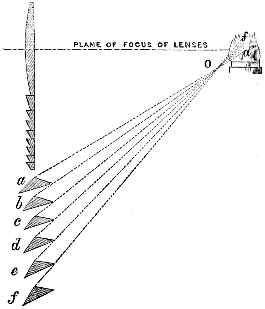
Fig. 87.
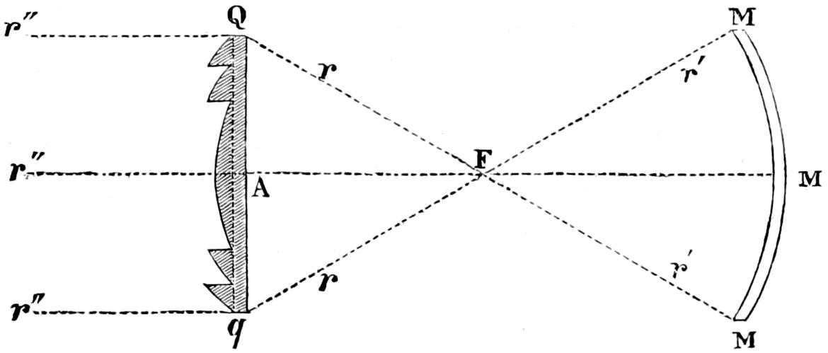
In the arc next the land, in fixed lights, a great loss of light ensues from the escape of the rays uselessly in that direction. So far back as 1834, I suggested the Application of Spherical Mirrors to fixed Dioptric Lights. placing a segment of a spherical mirror, with its centre of curvature coincident with F the focus of the system, so that the luminous pyramid MFM, of which the mirror MM forms the base, might be thrown back through the focal point and finally refracted into such a direction as to contribute to the effect of the lens QAq in seaward and opposite arc. In the diagram (fig. 87), r r indicate rays proceeding directly from F; r′ r′ rays reflected from MM through F, and finally refracted at QA q; and r″ r″ is the beam compounded of both. In the best glass-silvered mirrors, this accession of light would amount to nearly half of the light incident on them. In such an arrangement, a considerable radius is desirable to decrease the amount of aberration produced by a large flame. In the case of revolving lights of the first order, the radius would, of course, be limited to somewhat less than three feet, which is the focal distance of the lenses, between which and the focus, the reflecting segment must be placed; but in fixed lights, the lantern is the limit of radius, so that a focal length of five feet ten inches may be obtained. M. François ground some beautiful mirrors of three feet radius, which were afterwards tinned by his successor, M. Letourneau, by a new process discovered by himself;[72] and that gentleman is at present engaged in the construction of reflecting spherical segments 1200mm. square (about 16 superficial feet), to a radius of 1770mm. (5 feet 10 inches), which subtend a vertical arc of about 40°.
Arrangement of Dioptric Apparatus. The arrangements of the dioptric apparatus in the lightroom will be more fully understood by referring to the Plates.
Plate XIII. shews an elevation of a revolving dioptric apparatus of the first order; F is the focal point, in which the flame is placed; L, L great annular lenses, forming by their union an octagonal prism, with the lamp in its axis, and projecting, in horizontal beams, the light which they receive from the focus; L′L′, the upper lenses, forming by their union a frustum of an octagonal pyramid of 50° of inclination, and having their foci coinciding in the point F. They parallelise the rays of light which pass over the lenses. M, M are plane mirrors, placed above the pyramidal lenses L′L′, and so inclined as to project the beams reflected from them in planes parallel to the horizon; Z, Z are the lower zones, first used at Skerryvore, in the room of the curved mirrors which were used at Corduan. The lower part of Plate XIII. shews the moveable framework which carries the lenses and mirrors, and the rollers on which it circulates, with the clockwork which gives motion to the whole. Plate XIV. is the plan of the apparatus shewn in Plate XIII.
Plate XV. shews a section of a fixed dioptric light of the first order. F is the focal point in which the flame is placed; R, R cylindric refractors, forming by their union a prism of thirty-two sides, or a true cylinder, with the lamp in its axis, and producing a zone of light of equal intensity in every point of the horizon; M, M, curved mirrors, ranged in tiers above and below the cylindric refractors, and having their foci coinciding in the point F; the effect of the mirrors increases the power of the light, by collecting and transmitting the rays which would otherwise pass above and below them, without increasing the effect of the light. Plate XVI. gives the elements of the curved mirrors MM of Plate XV.
After the details given of the nature of the catadioptric zones, all that is needful is briefly to refer to Plate XVII., in which ABC and A′B′C′ shew the upper and lower zones which supply the place of the mirrors shewn at M, M, in Plate XV.; while DEF shews the cylindric belt as lately improved, with the diagonal joints M, N, C; and X, X, represent the diagonal supports for the cupola ABC. This plate, in connection with the enlarged view of the same apparatus at Plate XVIII., affords a complete explanation of the arrangement of all the parts.
Arrangement of the Dioptric Apparatus in the Lightroom. For the purpose of arranging the various parts of the dioptric apparatus in their proper positions, three gauges are employed. The first (fig. 88) is for ascertaining that the lenses l, l, meet at the proper horizontal angle, so that their axes shall meet with the proper inclination in F the focus. This is done by means of two arms, whose projecting points r, r, r, r touch the backs of the lenses, while the graduated arc c indicates the inclination of l, l, to l, l, or the complement of that inclination at F.
Fig. 88.
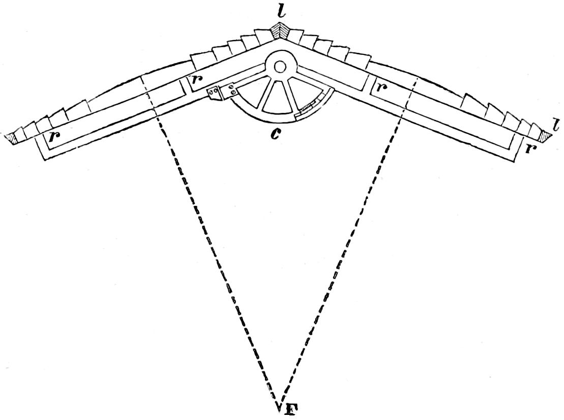
Fig. 89.
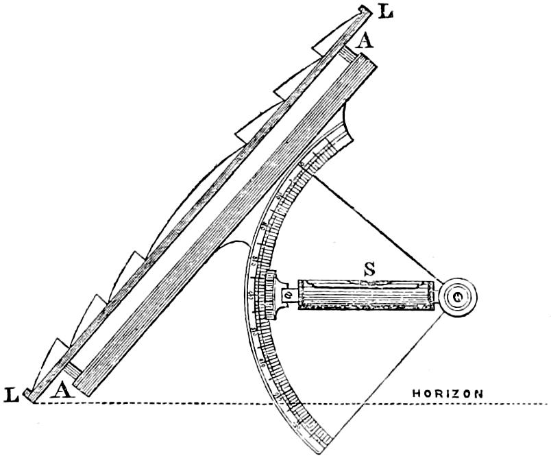
Again, for ascertaining the verticality of the main lenses, or for setting the subsidiary lenses or mirrors shewn in Plates XIII. and XIV., at the required angle of inclination, recourse is had to a clinometer (fig. 89) touching the back of the lens LL by means of studs at A, A, while the spirit-level S indicates, on the graduated limb, the amount of deviation from the vertical position of the instrument, whether accidental or intentional.
Fig. 90.
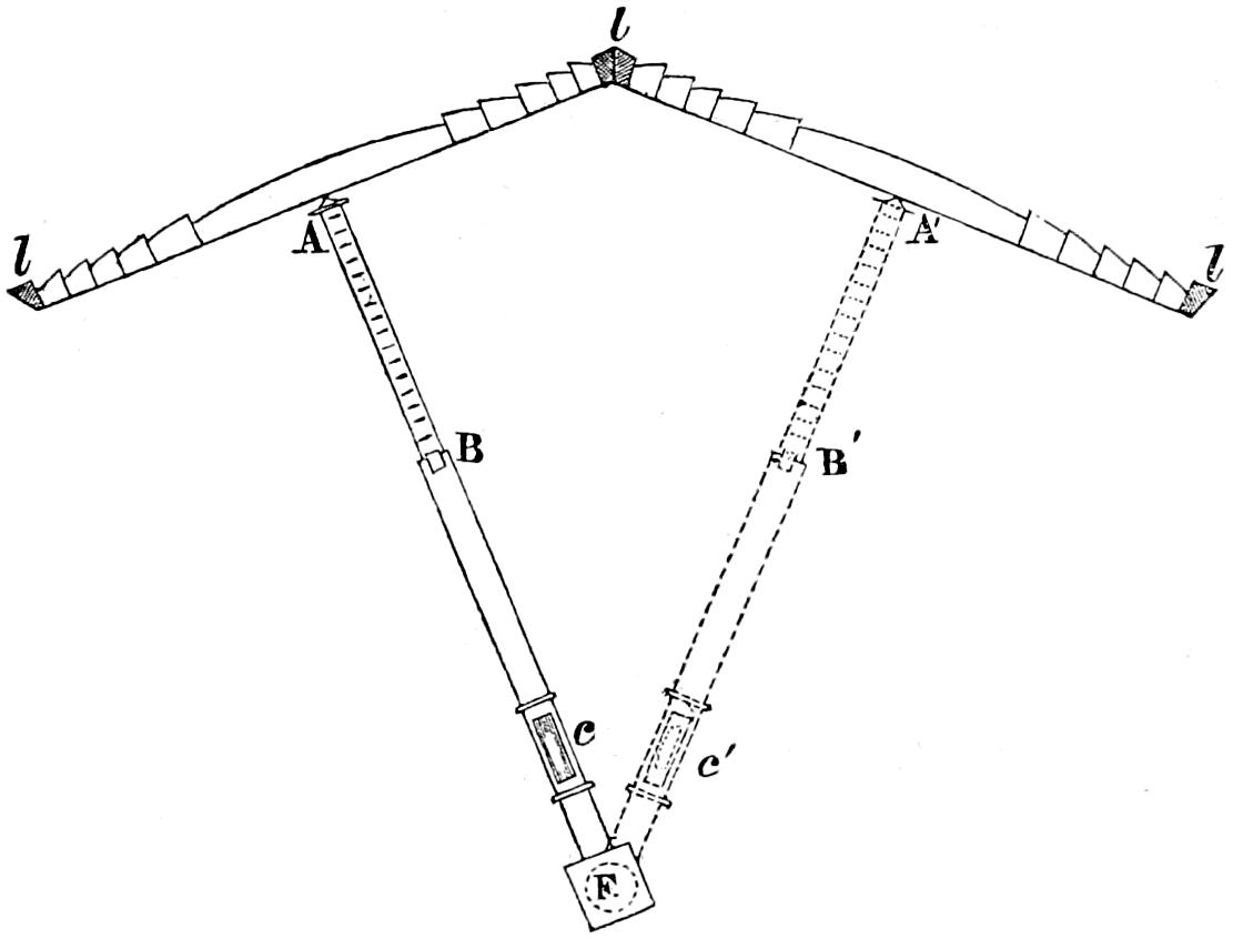
Lastly, to test the true position of the lamp itself, with reference to the lenses thus properly arranged, we apply a radius or trainer (fig. 90) which fits into the centre burner at F, while its point A touches the centre of the lens l, l; at B is a graduated slide, which admits of the trainer being lengthened or shortened to suit various focal distances; and the spirit-level at c at once corrects any error in the length of the trainer arising from depression or elevation, and also serves to indicate the proper level for the burner which is noticed at page 290, in speaking of the lamp. The dotted line F c′ B′A′ shews the position of the trainer in reference to an adjacent lens.
The elegant apparatus invented by Augustin Fresnel for Harbour Lights, on the same principle as that just described for Sea Lights, is shewn beneath (fig. 91). It consists of thirteen rings of glass of various diameters arranged one above another, in an oval form. The five middle rings have an interior diameter of 11·81 inches (30cm.), and like those of the larger apparatus, refract equally over the horizontal plane of the focus the light which they receive from it. The other rings or prisms, five of which are upper and three lower, are ground and set in such a manner, that they project all the light derived from the focus in a direction parallel to the other rays by total reflection.
Fig. 91.
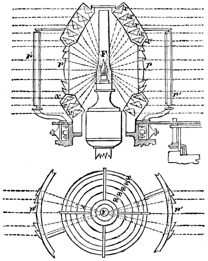
The arrangements of this apparatus, which is distinguished by the addition of external refractors arranged vertically, will be more fully understood by a reference to fig. 91, which shews its section and plan. F is the focal point in which the flame is placed; r, r cylindric refractors, forming by their union a cylinder with a lamp in its axis, and producing a zone of light of equal intensity all round the horizon; x, x are catadioptric prismatic rings acting by total reflection, and giving out zones of light of equal intensity at every point of the horizon. The dotted lines shew the course traversed by the rays of light which proceed from the lamp, and are acted upon by the rings of glass. The letters r′ r′ shew the external prisms, having their axes at right angles to those of the principal bent prisms, composing the refractors at r, r, and revolving around them. This ingenious application of the property of crossed prism is already described at page 264.
When this apparatus is employed to light only a part of the horizon, the rings are discontinued on the side next the land, and room is thus obtained for using a common fountain lamp; but when the whole horizon is illuminated, the apparatus must inclose the flame on every side; and it has in that case been found most convenient to employ the hydrostatic lamp of Thilorier, which has a balance of sulphate of zinc in solution.
An instrument differing from this small apparatus only in size, has lately been introduced into the Lighthouses in France, and has also been adopted in Scotland for lights in narrow seas. It has the same number of rings of glass as the small apparatus, and of the same proportional dimensions. Its internal diameter, however, is 500 millimètres (about 19¹⁄₂ inches). Drawings of the smaller apparatus are given at Plate XIX., which also contains the radii and the centre of curvature for the rings of the central dioptric belt; while the following Table gives the elements of the eight prismatic zones (above and below the belt), with the co-ordinates to their centres of curvature, measured from the arris A of the outer or emergent surfaces, in whatever position the zone may lie on the lathe. The dimensions are in millimètres; but may be easily converted into imperial inches, in the manner described in the Table of the Great Zones, which will be found in the Appendix:—
Number of Zone. Radii of curvature. Horizontal distance from the axis of the system. Vertical distance from the outer arris. Number of Zone. Radii of curvature. Horizontal distance from the axis of the system. Vertical distance from the outer arris.
Reflecting Surfaces (Convex).
I. 1094·5 723·5 833·78 V. 1222·9 523·6 1169·1
II. 1045·7 652·8 891·01 VI. 1249·4 544·0 1192·1
III. 1044·5 598·4 933·67 VII. 1150·4 593·5 1062·9
IV. 1087·3 551·9 1010·20 VIII. 1113·6 650·5 985·9
Outer Refracting Surfaces (Concave).
I. 1250·0 1290·7 303·19 V. 1250·00 1100·22 829·52
II. 1250·0 1274·2 445·89 VI. 1250·00 1112·74 821·16
III. 1250·0 1234·0 587·05 VII. 1250·00 1190·50 698·00
IV. 1250·0 1173·0 717·71 VIII. 1250·00 1251·90 557·22
Inner Refracting Surfaces (Convex).
I. 1250·0 150·67 1211·90 V. 1250·00 452·23 1184·20
II. 1250·0 228·19 1208·80 VI. 1250·00 453·07 1185·20
III. 1250·0 305·10 1203·35 VII. 1250·00 374·60 1196·00
IV. 1250·0 381·00 1195·30 VIII. 1250·00 294·35 1203·80
Power of Dioptric Instruments. The effect of an annular lens, in combination with the great lamp, may be estimated at moderate distances to be nearly equal to that of 3000 Argand flames of about an inch diameter; that of a cylindric refractor at about 250; and that of a curved mirror may perhaps on an average be assumed at about 10 Argand flames.
Orders of the French Lights. The dioptric lights used in France are divided into four orders, in relation to their power and range; but in regard to their characteristic appearances, this division does not apply, as, in each of the orders, lights of identically the same character may be found, differing only in the distance at which they can be seen, and in the expense of their maintenance. The four orders may be briefly described as follows:—
1st, Lights of the first order having an interior radius or focal distance of 36·22 inches (92cm.), and lighted by a lamp of four concentric wicks, consuming 570 gallons of oil per annum.
2d, Lights of the second order having an interior radius of 27·55 inches (70cm.), lighted by a lamp of three concentric wicks, consuming 384 gallons of oil per annum.
3d, Lights of the third order, lighted by a lamp of two concentric wicks, consuming 183 gallons of oil per annum. The instruments used in those lights are of two kinds, one having a focal distance of 19·68 inches (50cm.), and the other of 9·84 inches (25cm.).
4th, Lights of the fourth order, or harbour-lights, having an internal radius of 5·9 inches (15cm.), and lighted by a lamp of one wick, or Argand burner, consuming 48 gallons of oil per annum. This apparatus is, as already noticed, now more generally used of a larger scale, having a focal distance of 9·84 inches (25cm.), and a lamp of two concentric wicks, consuming about 130 gallons of oil per annum.[73]
Distinctions of the Dioptric Lights. Those four orders are not intended as distinctions; but are characteristic of the power and range of lights, which render them suitable for different localities on the coast, according to the distance at which they can be seen. This division, therefore, is analogous to that which separates our lights into sea-lights, secondary lights, and harbour-lights, terms which are used to designate the power and position, and not the appearance of the lights to which they are applied.
Each of the above orders is susceptible of certain combinations, which produce various appearances, and constitute the distinctions used for dioptric lights; but the following are those which have been actually employed as the most useful in practice:—
The first order contains, 1st, Lights producing, once in every minute, a great flash, preceded by a smaller one, by the revolution of eight great lenses and eight smaller ones combined with eight mirrors; 2d, Lights flashing once in every half minute, and composed of sixteen half lenses. Those lights may have the subsidiary parts simply catoptric, or diacatoptric; and, 3d, Fixed lights, composed of a combination of cylindric pieces, with curved mirrors or catadioptric zones ranged in tiers above and below them.
The second order comprises revolving lights with sixteen or twelve lenses, which make flashes every half minute; and fixed lights varied by flashes once in every four minutes, an effect which, as already noticed, is produced by the revolution of exterior cylindrical pieces.
The third order (larger diameter) contains common fixed lights, and fixed lights varied by flashes once in every four minutes.
The third order (smaller diameter) contains fixed lights, varied by flashes once in three minutes.
The fourth order has fixed lights varied by flashes once in every three minutes, and fixed lights of the common kind. It has been thought necessary to change the term “fixed lights varied by flashes,” for “fixed light with short eclipses,” because it has been found that, at certain distances, a momentary eclipse precedes the flash.
These distinctions depend upon the periods of revolution, rather than upon the characteristic appearance of the light; and therefore seems less calculated to strike the eye of a seaman, than those employed on the coasts of Great Britain and Ireland. In conformity with this system, and in consideration of the great loss of light which results from the application of coloured media, all distinctions based upon colour have been discarded in the French lights.
The distinctions are, in fact, only four in number, viz.: Fixed; Fixed, varied by flashes;[74] Revolving, with flashes once a minute; and Revolving, with flashes every half minute. To those might be added, Revolving, with bright periods once in two minutes, and perhaps Flashing once in five seconds (as introduced by me at the Little Ross, but I cannot say with such complete success as would induce me to recommend its general adoption). My own experience would also lead me to reject the distinction called “Fixed, varied by flashes,” which I do not consider as possessing a marked or efficient character.
Comparison of Dioptric and Catoptric Apparatus for Revolving Lights. Having thus fully described the nature of the catoptric and dioptric modes of illuminating lighthouses, I shall next compare the merits of both systems, with a view to determine their eligibility in revolving or in fixed lights.
Repeated experiments were made at Gullan-hill, which is distant from Edinburgh about fifteen miles, during the winters of 1832 and 1833, under the inspection of the Commissioners of Northern Lights, the result of which was, that the light of one of the great annular lenses used in the revolving lights of the first order, was equal to the united effect of about eight of the large reflectors employed in the revolving lights on the Scotch coast. It may be said, however, that the dia-catoptric[75] combination of pyramidal lenses and plane mirrors of Corduan, adds the power of more than two reflectors to the effect of the great lens; but it ought to be remembered that in the French lights, this additional power is used only to compensate for one of the defects of the system by lengthening the duration of the flash, and therefore contributes, if at all, only in a very indirect manner, to render the light visible to the mariner at a greater distance. M. Fresnel found, from the smaller divergence of the lens, that the eclipses were too long and the bright periods of the revolution too short; and he therefore determined to adopt the horizontal deviation of 7° for the upper lenses, with a view to remedy this defect. Assuming, therefore, that it were required to increase the number of reflectors in a revolving light of three sides, so as to render it equal in power to a dioptric revolving light of the first order, it would be necessary to place eight reflectors on each face, so that the greatest number of reflectors required for this purpose may be taken at twenty-four. M. Fresnel has stated the expenditure of oil in the lamp of four concentric wicks at 750 grammes of colza oil per hour; and it is found by experience at the Isle of May and Inchkeith, that the quantity of spermaceti oil consumed by the great lamp, is equal to that burned by from fourteen to sixteen of the Argand lamps used in the Scotch lights. It therefore follows that, by dioptric means, the consumption of oil necessary for between fourteen and sixteen reflectors, will produce a light as powerful as that which would require the oil of twenty-four reflectors in the catoptric system of Scotland; and, consequently, that there is an excess of oil equal to that consumed by ten reflectors, or 400 gallons in the year, against the Scotch system. But in order fully to compare the economy of producing two revolving lights of equal power by those two methods, it will be necessary to take into the calculation the interest of the first outlay in establishing them.
The expense of fitting up a revolving light with twenty-four reflectors, ranged on three faces, may be estimated at L.1298, and the annual maintenance, including the interest of the first cost of the apparatus, may be calculated at L.418, 8s. 4d. The fitting up a revolving light with eight lenses and the dia-catoptric accessory apparatus, may be estimated at L.1459, and the annual maintenance at L.354, 10s. 4d. It therefore follows, that to establish and afterwards maintain a catoptric light of the kind called revolving white, with a frame of three faces, each equal in power to a face of the dioptric light of Corduan, an annual outlay of L.63, 18s. more would be required for the reflecting light than for the lens light; while for a light of the kind called revolving red and white, whose frame has four faces, at least thirty-six reflectors would be required in order to make the light even approach an equality to that of Corduan; and the catoptric light would in that case cost L.225 more than the dioptric light.
The effect produced by burning an equal quantity of oil, in revolving lights on either system, may be estimated as follows:—In a revolving light, like that of Skerryvore, having eight sides, each lighting with its greatest power a horizontal sector of 4°, we have 32° (or units) of the horizon illuminated with the full power of 3200 Argand flames, and consequently an aggregate effect of 102,400 flames, produced by burning the oil required for sixteen reflectors; while in a catoptric apparatus, like that of the old light at Inchkeith, having seven sides of one reflector, each lighting with its greatest power a sector of 4°·25′, we have nearly 31° (or units) of the horizon illuminated with the full power of 400 Argand flames, and consequently an aggregate effect of 12,400 flames as the result of burning the oil required for seven reflectors. Hence, the effect of burning the same quantity of oil in revolving lights on either system, will be represented respectively by 16 7 12,400 = 28,343 for the catoptric, contrasted with 102,400 for the dioptric light; or, in other words, revolving lights on the dioptric principle use the oil more economically than those on the catoptric plan, nearly in the ratio of 3·6 to 1.
Comparison of Catoptric and Dioptric Apparatus for Fixed Lights. I shall now speak of fixed lights, to which the dioptric method is peculiarly well adapted. The effect produced by the consumption of a gallon of oil in a fixed light, with twenty-six reflectors, which is the smallest number that can be properly employed, may be estimated as follows:—The mean effect of the light spread over the horizontal sector, subtended by one reflector, as deduced from measurements made at each horizontal degree, by the method of shadows, is equal to 174 unassisted Argand burners. If, then, this quantity be multiplied by 360 degrees, we shall obtain an aggregate effect of 62,640, which, divided by 1040 (the number of gallons burned during a year in twenty-six reflectors), would give 60 Argand flames for the effect of the light maintained throughout the year by the combustion of a gallon of oil. On the other hand, the power of a catadioptric light of the first order, like that lately established at Girdleness, may be estimated thus:—The mean effect of the light produced by the joint effect of both the dioptric and catadioptric parts of a fixed light apparatus, may be valued at 450 Argand flames, which, multiplied by 360 degrees, gives an aggregate of 162,000; and if this quantity be divided by 570 (the number of gallons burned by the great lamp in a year), we shall have about 284 Argand flames for the effect of the light produced by the combustion of a gallon of oil. It would thus appear that in fixed lights, the French apparatus, as lately improved, produces, as the average effect of the combustion of the same quantity of oil over the whole horizon, upwards of four times the amount of light that is obtained by the catoptric mode; although, in certain directions, opposite the axis of each reflector, the catoptric light be fully 50 per centum more powerful than the dioptric light.
But the great superiority of the dioptric method chiefly rests upon its perfect fulfilment of an important condition required in a fixed light, by distributing the rays equally in every point of the horizon. In the event of the whole horizon not requiring to be illuminated, the dioptric light would lose a part of its superiority in economy, and when half the horizon only is lighted, it would be more expensive than the reflected light; but the greater power and more equal distribution of the light, may be considered of so great importance, as far to outweigh the difference of expense. In the latter case, too, an additional power (as noticed p. 293) can be given to the dioptric light, by placing at the landward side of the lightroom, spherical mirrors with their centres in the focus of the refracting apparatus.[76] The luminous cones, or pyramids of which such reflectors would form the bases, instead of passing off uselessly to the land, would thus be thrown back through the focal point, and finally refracted, so as to increase the effect of the light seaward, by nearly one-third of the light which would otherwise be lost.
The expense of establishing a fixed light composed of twenty-six reflectors, may be estimated at L.950, and its annual maintenance, including interest on the first cost of the apparatus, may be reckoned at L.425, 10s.: and the expense of fitting up a fixed light on the dioptric principle with catadioptric zones is L.1511, while its annual maintenance may be taken at L.285, 6s. 4d. It thus appears that the annual expenditure of the dioptric fixed light is L.140, 3s. 8d. less than that of a fixed light composed of twenty-six reflectors; while the average effect, equally diffused over the horizon, is four times greater.
The comparative views already given of the catoptric and dioptric modes of illuminating lighthouses, demonstrate that the latter produces more powerful lights by the combustion of the same quantity of oil; while it is obvious that the catoptric system insures a more certain exhibition of the light, from the fountain-lamps being less liable to derangement than the mechanical lamps used in dioptric lights. The balance, therefore, of real advantages or disadvantages, and, consequently, the propriety of adopting the one or the other system, involves a mixed question, not susceptible of a very precise solution, and leaving room for different decisions, according to the value which may be set upon obtaining a cheaper and better light, on the one hand, as contrasted, on the other, with less certainty in its exhibition.
Summary of considerations as to the fitness of the two systems for Revolving Lights. A few general considerations, serving briefly to recapitulate the arguments for and against the two systems, may not be out of place. And, first, regarding the fitness of dioptric instruments for revolving lights, it appears from the details above given,—
1st, That by placing eight reflectors on each face of a revolving frame, a light may be obtained as brilliant as that derived from the great annular lens; and that, in the case of a frame of three sides, the excess of expense by the reflecting mode, would be L.63, 18s.; and in the case of a frame of four sides, the excess would amount to L.225.
2d, That for burning oil economically in revolving lighthouses, which illuminate every point of the horizon successively, the lens is more advantageous than the reflector in the ratio of 3·6 to 1.
3d, That the divergence of the rays from the lens being less than from the reflector, it becomes difficult to produce, by lenses, the appearance which characterises the catoptric revolving lights, already so well known to British mariners; and any change of existing lights which would, of course, affect their appearance, must, therefore, involve many grave practical objections which would not at all apply to the case of new lights.
4th, That the uncertainty in the management of the lamp renders it more difficult to maintain the revolving dioptric lights without risk of extinction, an accident which has several times occurred at Corduan and other lighthouses both in France and elsewhere.
5th, That the extinction of one lamp in a revolving catoptric light is not only less probable, but leads to much less serious consequences than the extinction of the single lamp in a dioptric light; because, in the first case, the evil is limited to diminishing the power of one face by an eighth part; whilst, in the second, the whole horizon is totally deprived of light. The extinction of a lamp, therefore, in a dioptric light, leads to evils which may be considered infinitely great in comparison with the consequences which attend the same accident in a catoptric light.
Summary of considerations as to the fitness of the two systems for Fixed Lights. In comparing the fixed dioptric, and the fixed catoptric apparatus, the results may be summed up under the following heads:—
1st, It is impossible, by means of any practicable combination of paraboloïdal reflectors, to distribute round the horizon a zone of light of exactly equal intensity; while this may be easily effected, by dioptric means, in the manner already described. In other words, the qualities required in fixed lights cannot be so fully obtained by reflectors as by refractors.
2d, The average light produced in every azimuth by burning one gallon of oil in Argand lamps, with reflectors, is only about one-fourth of that produced by burning the same quantity in the dioptric apparatus; and the annual expenditure is L.140, 3s. 8d. less for the entire dioptric light than for the catoptric light.
3d, The characteristic appearance of the fixed reflecting light in any one azimuth would not be changed by the adoption of the dioptric method, although its increased mean power would render it visible at a greater distance in almost every direction; the only exception being in the azimuths opposite the axis of each reflector, where the catoptric light has an excess of power equal to about 50 per centum.
4th, From the equal distribution of the rays, the dioptric light would be observed at equal distances in every point of the horizon; an effect which cannot be fully attained by any practicable combination of paraboloïdal reflectors.
5th, The inconveniences arising from the uncertainty which attends the use of the mechanical lamp, are not perhaps so much felt in a fixed as in a revolving light, because the greater simplicity of the apparatus admits of easier access to it, in case of accident.
6th, But the extinction of a lamp in a catoptric light, leaves only one twenty-sixth part of the horizon without the benefit of the light, and the chance of accident arising to vessels from it, may, therefore, be considered as incalculably less than the danger resulting from the extinction of the single lamp of the dioptric light, which deprives the whole horizon of light.
7th, There may also, in certain situations, be some risk arising from irregularity in the distances at which the same fixed catoptric light can be seen in the different azimuths. This defect, of course, does not exist in the dioptric light.
Advantages and disadvantages of both systems under certain circumstances. There can be little doubt, that the more fully the system of Fresnel is understood, the more certainly will it be preferred to the catoptric system of illuminating lighthouses, at least in those countries where this important branch of administration is conducted with the care and solicitude which it deserves. It must not, however, be imagined, that there are no circumstances in which the catoptric system is not absolutely preferable to illumination by means of lenses. We have hitherto attended only to horizontal divergence and its effects, and this is unquestionably the more important view; but the consideration of vertical divergence must not be altogether overlooked. Now, while it is obvious that vertical divergence, at least above the horizon, involves a total loss of the light which escapes uselessly upwards into space, it is no less true, that if the sheet of light which reaches the most distant horizon of the lighthouse, however brilliant, were as thin as the absence of all vertical divergence would imply, it would be practically useless; and some measure of dispersion in the arc below the horizon is therefore absolutely indispensable to constitute a really useful light. In the reflector, the greatest vertical divergence below the horizontal plane of the focus is 16° 8′, and that of the lens is about 4° 30′.
Let us consider for a moment the bearing of those facts upon the application of the two modes of illumination to special circumstances. The powerful beam of light transmitted by the lens, peculiarly fits that instrument for the great sea-lights which are intended to warn the mariner of his approach to a distant coast which he first makes on an over-sea voyage; and the deficiency of its divergence, whether horizontal or vertical, is not practically felt as an inconvenience in lights of that character, which seldom require to serve the double purpose of being visible at a great distance, and at the same time of acting as guides for dangers near the shore. For such purposes, the lens applies the light much more economically than the reflector, because, while the duration of its least divergent beam is nearly equal to that of the reflector, it is eight times more powerful. A revolving system of eight lenses illuminates an horizontal arc of 32° with this bright beam. The reflector, on the other hand, spreads the light over a larger arc of the horizon; and, while its least divergent beam is much less powerful than that of the lens, the light which is shed over its extreme arc is so feeble as to be practically of little use in lights of extensive range, even during clear weather. When a lighthouse is placed on a very high headland, however, the deficiency of divergence in the vertical direction is often found to be productive of some practical inconvenience; but this defect may be partially remedied by giving to the lenses a slight inclination outwards from the vertical plane of the focus, so as to cause the most brilliant portion of the emergent beam to reach the visible horizon which is due to the height of the lantern. It may be observed, also, that a lantern at the height of 150 feet, which, taking into account the common height of the observer’s eye at sea, commands a range of upwards of 20 English miles, is sufficient for all the ordinary purposes of the navigator, and that the intermediate space is practically easily illuminated, even to within a mile of the lighthouse, by means of a slight inclination of the subsidiary mirrors, even where the light from the principal part of the apparatus passes over the seaman’s head. For the purpose of leading lights, in narrow channels, on the other hand, and for the illumination of certain narrow seas, there can be no doubt that reflectors are much more suitable and convenient. In such cases, the amount of vertical divergence below the horizon, forms an important element in the question, because it is absolutely necessary that the mariner should keep sight of the lights even when he is very near them; while there is not the same call for a very powerful beam which exists in the case of sea-lights. Yet even in narrow seas, where low towers, corresponding to the extent of the range of the light, are used, but where it is, at the same time, needful to illuminate the whole or the greater part of the horizon, the use of dioptric instruments will be found almost unavoidable, especially in fixed lights, as well from their equalizing the distribution of the light in every azimuth, as from their much greater economy in situations where a large annual expenditure would often be disproportionate to the revenue at disposal. In such places, where certain peculiarities of the situation require the combination of a light equally diffused over the greater portion of the horizon, along with a greater vertical divergence in certain azimuths, than dioptric instruments afford, I have found it convenient and economical to add to the fixed refracting apparatus a single paraboloïdal reflector, in order to produce the desired effect, instead of adapting the whole light to the more expensive plan for the sake of meeting the wants of a single narrow sector of its range. In other cases, where the whole horizon is to be illuminated, and great vertical divergence is at the same time desirable, a slight elevation of the burner, at the expense, no doubt, of a small loss of light, is sometimes resorted to, and is found to produce, with good effect, the requisite depression of the emergent rays.
In certain situations, where a great range and, consequently, a powerful light must be combined with tolerably powerful illumination in the immediate vicinity of the lighthouse, we might, perhaps, advantageously adopt a variation of the form and dimensions of the mirrors employed, so as to resemble those formerly employed at the Tour de Corduan, which were of considerably larger surface and longer focal distance than those which are used in Britain. If such a form were adopted, the power of the light for the purpose of the distant range would be increased; and I would propose to compensate for the deficiency of divergence consequent on a long focal distance, by placing a second burner in some position between the parameter and the vertex, and slightly elevated above the axis of the instrument, so as to throw the greater portion of the beam resulting from this second burner below the horizontal plane of the focus. Such an expedient is no doubt somewhat clumsy and would at the same time involve the consumption of twice the quantity of oil used in an ordinary catoptric light; but I can still conceive it to be preferable, in certain situations, to the use of lenses alone.
Thus it appears that we must not too absolutely conclude against one, or in favour of the other mode of illumination for lighthouses; but, as in every other department of the arts, we shall find the necessity of patiently weighing all the circumstances of each particular case that comes before us, before selecting that instrument, or combination of instruments, which appears most suitable.
Distinctions of the Dioptric Lights, and the application of coloured media. The mode of distinguishing lights in the system of Fresnel, depends more upon their magnitude and the measured interval of the time of their revolution, than upon their appearance; and no other very marked distinctions, except Fixed and Revolving, have been successfully attempted in France. As above stated, I consider the distinction of the fixed light varied by flashes, to possess an appearance too slightly differing from that of a revolving light, to admit of its being safely adopted in situations where revolving lights are near. The trial which I made at the Little Ross, in the Solway Frith, of producing, by means of lenses, a light flashing once in five seconds of time, although successful so far as mere distinction is concerned, has several practical defects, arising from the shortness of the duration of the flashes, compared with the powerful effect of the fixed part of the apparatus, which I consider sufficient to prevent its adoption in future, especially considering that a much more marked appearance can be produced, by means of reflectors, as has been done at the Buchanness in Aberdeenshire, and the Rhinns of Islay in Argyllshire. Coloured media have never, so far as I know, been applied to Dioptric apparatus, except in the case of the Maplin Light at the mouth of the Thames, and Cromarty Point Light at the entrance to the Cromarty Frith, and in both instances successfully. The enormous loss of light, however, amounting to no less than 0·80 of the whole incident rays, forms a great bar to the adoption of colour as a distinction; and any means which could tend to lessen that absorption, and at the same time produce the characteristic appearance, would be most valuable. I have tried some glasses of a pink tinge, prepared by M. Letourneau of Paris, whose absorption does not exceed 0·57 of the incident rays; but the appearance of the light, at a distance, is much less marked than that produced by the glasses used in Britain.[77] Such deficiency of characteristic colour might lead to serious consequences, as the transmission of white rays, through a hazy atmosphere, too often produces, by absorption, a reddish tinge of the light, for which the less marked appearance given by the paler media might be easily mistaken. This colouring power of absorption is so well known, that red lights are seldom used except in direct contrast with white ones; but, on a coast so thickly studded with Lighthouses as that of Britain, the number of distinctions is insufficient to supply all our wants, so that we are sometimes reluctantly compelled to adopt a single red light in some situation of lesser importance, or which, from some local circumstances and the appearance of the lights which must be seen by the mariner before passing it, is not likely to be mistaken. The great loss of light by coloured media causes the red beam, in a revolving light, to be seen at a shorter distance than the white; and it is conceivable that, in certain circumstances, this might lead the mariner to mistake a red and white light for a white light revolving at half the velocity. Such a mistake might perhaps prove dangerous; but the lights are generally so situated that there is ample time for the mariner, after first discovering the red light, and thus correcting any mistake, to shape his course accordingly. All other coloured media except red have been found useless as distinctions for any lights of extensive range, and fail to be efficient, owing to the necessity of absorbing almost all the light before a marked appearance can be obtained. In a few pier or ferry lights, green and blue media have been tried, and found available at the distance of a few cables’ lengths.
It seems to be a natural consequence of the physical distribution of light, that fixed lights, which illuminate the whole horizon, should be less powerful than revolving lights which have their effect concentrated within narrow sectors of the horizon. Any attempt to increase the power of fixed lights is, therefore, worthy of attention; Captain Basil Hall’s proposal for producing the appearance of Fixed Lights by rapid movement. and when the late Captain Basil Hall proposed a plan for effecting this object, it received, as it deserved, the full consideration of the Lighthouse Board, who authorised me to repeat Captain Hall’s experiments, and verify his results by observations made at a considerable distance. As some interesting phenomena of irradiation were evolved in the course of those trials, I think it right to give some account of the results which were obtained, as they bear upon various questions connected with the practical arrangements of Lighthouses, under certain circumstances.
In revolving lights on the dioptric principle, the annular lens of Fresnel, as formerly stated, is employed. This instrument, as the reader already knows, possesses the property of projecting to the horizon, in the form of one pencil or beam, all the light which falls on its inner surface from a lamp placed in its principal focus. The consequence of this action is, that when several lenses are so arranged as to form a right prism which circulates round a lamp placed in the common focus, a distant observer receives from each lens, as its axis crosses his line of vision, a bright flash, which is succeeded by total darkness, when one of the dark spaces intermediate between the lenses passes over his eye; and this succession of bright flashes alternating with dark intervals, produces the characteristic appearance of a revolving light.
The fixed light, on the other hand, presents to the eye a steady and unchanging appearance; and the chief object to be obtained in its construction, is to unite the greatest brilliancy with an equal distribution of the light in every direction. The condition of perfect distribution, as already said, is most rigorously fulfilled by the use of refracting zones or belts, which form, by their union, a cylinder enveloping the flame placed in its centre, and possess the property of refracting the light in the vertical direction only, without affecting its natural divergence horizontally. The light from the focus which is incident on the inner surface of the belt is therefore projected forwards in the shape of a flat ring of equal brilliancy all round the horizon.
This repetition may seem needless, but it is hoped it will be found useful in rendering intelligible the following outline of the plan proposed by Captain Hall for the improvement of fixed lights, and the account of the trials that were made with that object in view.
The familiar experiment of whirling a burning stick quickly round the head, so as to produce a ribbon of light, proves the possibility of causing a continuous impression on the retina by intermittent images succeeding each other with a certain rapidity. From the moderate velocity at which this continuity of impression is obtained, we should be warranted in concluding, a priori, that the time required to make an impression on the retina is considerably less than the duration of the impression itself; for the continuity of effect must, of course, be caused by fresh impulses succeeding each other before the preceding ones have entirely faded. If it were otherwise, and the time required to make the impression were equal to the duration of the sensation, it would obviously be impossible to obtain a series of impulses so close or continuous in their effects as to run into and overlap each other, and thus throw out the intervals of darkness; because the same velocity which would tend to shorten the dark intervals, would also curtail the bright flashes, and thus prevent their acting on the eye long enough to cause an impression. Accordingly, we find that the duration of an impression is in reality much greater than the time required for producing the effect on the retina. It is stated by Professor Wheatstone, in the London Transactions for 1834, that only about one millionth part of a second is required for making a distinct impression on the eye; and it appears, from a statement made by Lamé, at p. 425 of his Cours de Physique, that M. Plateau found that an impression on the retina preserved its intensity unabated during one hundredth of a second, so that, however small those times may be in themselves, the one is yet 10,000 greater than the other.
It has been ascertained by direct experiment,[78] that the eye can receive a fresh impression before the preceding one has faded; and, indeed, if this were impossible, absolute continuity of impression from any succession of impulses, however rapid, would seem to be unattainable; and the approach to perfect continuity would be inversely as the time required to make an impression.
Effects of rapid motion on the power of Lights. From this property which bright bodies passing rapidly before the eye possess of communicating a continuous impression to the sense of sight, Captain Hall conceived the idea, not merely of obtaining all the effects of a fixed light, by causing a system of lenses to revolve with such a velocity as to produce a continuous impression, but, at the same time, of obtaining a much more brilliant appearance, by the compensating influence of the bright flashes, which he expected would produce impulses sufficiently powerful and durable to make the deficiency of light in the dark spaces almost imperceptible. The mean effect of the whole series of changes would, he imagined, be thus greatly superior to that which can be obtained from the same quantity of light equally distributed, as in fixed lights, over the whole horizon. Now this expectation, if it be considered solely in reference to the physical distribution of the light, involves various difficulties. The quantity of light subjected to instrumental action is the same whether we employ the refracting zones at present used in fixed dioptric lights, or attempt to obtain continuity of effect by the rapid revolution of lenses; and the only difference in the action of those two arrangements is this, that while the zones distribute the light equally over the whole horizon, or rather do not interfere with its natural horizontal distribution, the effect of the proposed method is to collect the light into pencils, which are made to revolve with such rapidity, that the impression from each pencil succeeds the preceding one in time to prevent a sensible occurrence of darkness. To expect that the mean effect of the light, so applied, should be greater than when it is left to its natural horizontal divergence, certainly appears at first to involve something approaching to a contradiction of physical laws. In both cases, the same quantity of light is acted upon by the instrument; and in either case, any one observer will receive an impression similar and equal to that received by any other stationed at a different part of the horizon; so that, unless we imagine that there is some loss of light peculiar to one of the methods, we are, in the physical view of the question, shut up to the conclusion, that the impressions received by each class of observers must be of equal intensity. In other words, the same quantity of light is by both methods employed to convey a continuous impression to the senses of spectators in every direction, and in both methods equality of distribution is effected, since it does not at all consist with our hypothesis, that any one observer in the same class should receive more or less than his equal share of the light. Then, as to the probability of the loss of light, it seems natural to expect that this should occur in connection with the revolving system, because the velocity is an extraneous circumstance, by no means necessary to an equal distribution of the light, which can, as we already know, be more naturally and at the same time perfectly, attained by the use of the zones.
On the other hand, it must not be forgotten, that although the effect of both methods is to give each part of the horizon an equal share of light, there is yet this difference between them, that while the light from the zones is equally intense at every instant of time, that evolved by the rapidly circulating lenses is constantly passing through every phase between total darkness and the brightest flash of the lens; and this difference, taken in connection with some curious physiological observations regarding the sensibility of the retina, gives considerable countenance to the expectation on which Captain Hall’s ingenious expedient is based. The fact which has already been noticed, and which the beautiful experiments of M. Plateau and Professor Wheatstone have of late rendered more precise, that the duration of an impression on the retina is not only appreciable, but is much greater than the time required to cause it, seems to encourage us in expecting, that while the velocity required to produce continuity of effect would not be found so great as to interfere with the formation of a full impression, the duration of the impulse from each flash would remain unaltered, and the dark intervals which do not excite the retina would, at the same time, be shortened, and that, therefore, we might in this manner obtain an effect on the senses exceeding the brilliancy of a steady light distributed equally in every direction by the ordinary method. Some persons, indeed, who have speculated on this subject, seem even to be of opinion, that, so far from the whole effect of the series of continuous impressions being weakened by a blending of the dark with the bright intervals, the eye would in reality be stimulated by the contrast of light and darkness, so as thereby to receive a more complete and durable impulse from the light. It is obvious, however, that this question regarding the probable effect to be anticipated from a revolution so rapid as to cause a continuous impression, could only have been satisfactorily answered by an appeal to experiment.
In experimenting on this subject, I used the apparatus formerly employed by Captain Hall. It consisted of an octagonal frame, which carried eight of the discs that compose the central part of Fresnel’s compound lens, and was susceptible of being revolved slowly or quickly at pleasure, by means of a crank-handle and some intermediate gearing. The experiments were nearly identical with those made by Captain Hall, who contrasted the effect of a single lens at rest, or moving very slowly, with that produced by the eight lenses, revolving with such velocity as to cause an apparently continuous impression on the eye. To this experiment I added that of comparing the beam thrown out by the central portion of a cylindric refractor, such as is used at the fixed light of the Isle of May, with the continuous impression obtained by the rapid revolution of the lenses. Captain Hall made all his comparisons at the short distance of 100 yards; and in order to obtain some measure of the intensity, he viewed the lights through plates of coloured glass until the luminous discs became invisible to the eye. I repeated those experiments at Gullan, under similar circumstances, but with very different results. I shall not, however, enter upon the discussion of those differences here, although they are susceptible of explanation, and are corroborative of the conclusions at which I arrived, by comparing the lights from a distance of 14 miles; but shall briefly notice the more important results which were obtained by the distant view. They are as follows:—
1. The flash of the lens revolving slowly was very much larger than that of the rapidly revolving series; and this decrease of size in the luminous object presented to the eye, became more marked as the rate of revolution was accelerated, so that, at the velocity of eight or ten flashes in a second, the naked eye could hardly detect it, and only a few of the observers saw it; while the steady light from the fixed refractor was distinctly visible.
2. There was also a marked falling off in the brilliancy of the rapid flashes as compared with that of the slow ones; but this effect was by no means so striking as the decrease of volume.
3. Continuity of impression was not attained at the rate of five flashes in a second, but each flash appeared to be distinctly separated by an interval of darkness; and even when the nearest approach to continuity was made, by the recurrence of eight or ten flashes in a second, the light still presented a twinkling appearance, which was well contrasted with the steady and unchanging effect of the cylindric refractor.
4. The light of the cylindric refractor was, as already stated, steady and unchanging, and of much larger volume than the rapidly revolving flashes. It did not, however, appear so brilliant as the flashes of the quickly revolving lenses, more especially at the lower rate of five flashes in a second.
5. When viewed through a telescope, the difference of volume between the light of the cylindric refractor and that produced by the lenses at their greatest velocity was very striking. The former presented a large diffuse object of inferior brilliancy, while the latter exhibited a sharp pin-point of brilliant light.
Upon a careful consideration of these facts it appears warrantable to draw the following general conclusions:—
1. That our expectations as to the effects of light, when distributed according to the law of its natural horizontal divergence, are supported by observed facts as to the visibility of such lights, contrasted with those whose continuity of effect is produced by collecting the whole light into bright pencils, and causing them to revolve with great velocity.
2. It appears that this deficiency of visibility seems to be chiefly due to a want of volume in the luminous object, and also, although in a less degree, to a loss of intensity, both of which defects appear to increase in proportion as the motion of the luminous object is accelerated.
3. That this deficiency of volume is the most remarkable optical phenomenon connected with the rapid motion of luminous bodies, and that it appears to be directly proportional to the velocity of their passage over the eye.
4. That there is reason to suspect that the visibility of distant lights depends on the volume of the impression in a greater degree than has perhaps been generally imagined.
5. That, as the size and intensity of the radiants causing these various impressions to a distant observer were the same, the volume of the light and, consequently, cæteris paribus, its visibility, are, within certain limits, proportionate to the time during which the object is present to the eye.
Such appear to be the general conclusions which those experiments warrant us in drawing; and the practical result, in so far as lighthouses are concerned, is sufficient to discourage us from attempting to improve the visibility of fixed lights in the manner proposed by Captain Hall, even supposing the practical difficulties connected with the great centrifugal force generated by the rapid revolution of the lenses to be less than they really are.
Connection of the experiments with Irradiation. This decrease in the volume of the luminous object caused by the rapid motion of the lights is interesting, from its apparent connection with the curious phenomenon of irradiation. When luminous bodies, such as the lights of distant lamps, are seen by night, they appear much larger than they would do by day; and this effect is said to be produced by irradiation. M. Plateau, in his elaborate essay on this subject, after a careful examination of all the theories of irradiation, states it to be his opinion, that the most probable mode of accounting for the various observed phenomena of irradiation is to suppose, that, in the case of a night-view, the excitement caused by light is propagated over the retina beyond the limits of the day-image of the object, owing to the increased stimulus produced by the contrast of light and darkness; and he also lays it down as a law confirmed by numerous experiments, that irradiation increases with the duration of the observation. It appears, therefore, not unreasonable to conjecture, that the deficiency of volume observed during the rapid revolution of the lenses may have been caused by the light being present to the eye so short a time, that the retina was not stimulated in a degree sufficient to produce the amount of irradiation required for causing a large visual object. When, indeed, the statement of M. Plateau, that irradiation is proportional to the duration of the observation, is taken in connection with the observed fact, that the volume of the light decreased as the motion of the lenses was accelerated, it seems almost impossible to avoid connecting together the two phenomena as cause and effect.
VARIOUS GENERAL CONSIDERATIONS CONNECTED WITH LIGHTHOUSES.
In the course of supplying the numerous wants of navigation, it will often be found necessary to cut off, on a given bearing, the beam proceeding from a Lighthouse, as a guide to the seaman to avoid some shoal, or as a hint to put about and seek the opposite side of a channel. This is attended with some little practical difficulty, especially in lights from reflectors arranged externally on a circle, because a certain portion of light, chiefly due to the divergence caused by the size of the flames, and partly from the effects of the diffraction or inflexion of the light, spreads faintly over a narrow sector between the light arc and the dark one. Masking Lights. It becomes necessary, of course, to make allowance for this penumbral arc by increasing the masked portion of the lantern; and, where a very sharp line of demarcation is required, a board is sometimes placed on the outside of the Lightroom, in such a position, and of such length, that while it does not enter the boundaries of the luminous sector, it prevents the more powerful part of the penumbral beam from reaching the observer’s eye. This effect is, of course, more conveniently produced, where the circumstances admit of its adoption, by distributing the reflectors round the concave side of the lantern, towards the land; but such an arrangement is inapplicable when the illuminated sector exceeds the dark one. I have found, by observation, that the sector intercepted between the azimuth on which the lantern is masked and that on which total darkness is produced to an observer, at moderate distances, may be estimated at not less than 3° for dioptric, and 7° for catoptric lights of the highest class.[79]
Those quantities may therefore serve to guide the Lighthouse engineer to approximate more rapidly to his object, as he will generally be safe in increasing the dark sector, by one or other of the above constants, according to the kind of apparatus employed. I need not add, that in a matter of this kind, a final appeal to actual observation is, in all cases, indispensable.
A few words on the subject of double lights, naturally spring out of what has been said about the masking of lights. Double Lights. The term double lights is properly and distinctly confined to lights on different levels, but not necessarily (as leading-lights are) in separate towers. The sole object of using double lights is for distinction from neighbouring lights; and they are unquestionably most effective in this respect, when they are placed in the same tower. In this point of view, therefore, I shall speak of them; and it is obvious that all that peculiarly belongs to them is, that the difference of level between them shall be sufficiently great to present the lights as separate objects to the eye of the seaman, when placed at the greatest distance at which it may be desirable that he should be able to recognise their characteristic appearance. In many cases it is not necessary (but it is certainly always desirable) that the lights should, from the first moment of their being seen, be known as double lights; but in others, it may well consist with safety, that two lights, which appear as a single light when first seen at the distance of 20 miles, shall at 15 or 10 miles distance be discovered to be double. Now we should at first be apt hastily to imagine, that all that is required to produce that effect, is to raise the one light above the other to such an extent, that the distance between them shall be somewhat more than a minimum visibile at the most distant point of observation, or, in other words, that the difference of the height of the lights should be such as to subtend to the eye at the point of observation, an angle greater than 13″·02, which is the subtense of a minimum visibile during the day.[80] But the effect of irradiation, to which I have already alluded, tends to blend together the images of the lights long before their distance apart has become so low a fraction of the observer’s distance from the Lighthouse, as to subtend so small an angle; and I have accordingly found by experiments, conducted under various circumstances, and at various distances, that repeated observations gave me 3′ 18″ as the mean of the subtenses calculated in reference to the distances at which the lights began to be blended into one.
Adopting this as the smallest angle which the two lights should subtend at the observer’s eye, we may find the least vertical distance between them which will cause them to appear as separate objects by the following formula:
H = 2 Δ . tan θ
in which Δ is the observer’s distance in feet; θ, half the subtense, = 1′ 39″; and H the required height of the tower between the two lights in feet. The following Table gives the height in feet corresponding to the distance in nautic miles, from 1 to 20 inclusive: the heights, which are the bases of similar isosceles triangles, increase, of course, in an arithmetical series:
Distance of the observer in Nautic Miles. Vertical distance in feet between the Lights. Distance of the observer in Nautic Miles. Vertical distance in feet between the Lights.
1 6·02 11 66·22
2 12·04 12 72·24
3 18·06 13 78·26
4 24·08 14 84·28
5 30·10 15 90·30
6 36·12 16 96·32
7 42·14 17 102·34
8 48·16 18 108·36
9 54·18 19 114·38
10 60·20 20 120·40
Akin to the subject of Double Lights, is that of Leading Lights. Leading Lights, the object of which is to indicate to the mariner a given line of direction by their being seen in one line. In most instances, this line of direction is used to point out the central part of a narrow channel; and the alternate opening of the lights, on either side of their conjunction, serves to indicate to the mariner (who ought to conjoin with his watching of the lights the observation of the elapsed time and also frequent soundings) the proper moment for changing his tack. In some places, the line of conjunction of the lights is placed nearer to one side of a channel than the other, according as the set of the tides, or the position of shoals, may seem to require. In other situations, this line only serves as a cross-bearing to shew the mariner his approach to some danger, or to indicate his having passed it, and thus to assure him of his entry on wider sea-room. Similar considerations to those which determine the difference of elevation for double lights regulate the choice of the distance between two leading lights; but the question is less narrow, and may be generally solved graphically by simply drawing the lines on an accurate chart of the locality. In some few situations, the configuration of the coast does not admit of a separation between the lights, sufficient to cause what is called a sharp intersection; but, in most cases, there is room enough to place them so far apart, that but a few yards of deviation in the vessel’s course, from the exact line of the conjunction of the lights in one, produces a distinct opening between them on the opposite side of that line. In order to insure the requisite sharpness of intersection, the distance between the lights, wherever attainable, should be not less than one-sixth of the distance between the more seaward of the two Towers and that point at which the seaman begins to use the line of conjunction as his guide. I have only to add, that in situations where the land prevents a considerable separation between leading lights, they should be placed as nearly on one level as is consistent with their being seen as vertically separated, so as in some measure to compensate for their horizontal nearness, by rendering their intersection more sharp and striking than it can be where the observer must draw from the upper light an imaginary perpendicular in his mind, and then estimate the separation of the lights by the sine of an angle, which decreases as the difference of their apparent elevations increases.
Distribution of Lights on a Coast. The considerations which enter into the choice of the position and character of the Lights on a line of coast, are either, on the one hand, so simple and self-evident as scarcely to admit of being stated in a general form, without becoming mere truisms; or are, on the other hand, so very numerous and often so complicated as scarcely to be susceptible of compression into any general laws. I shall not, therefore, do more than very briefly allude to a few of the chief considerations which should guide us in the selection of the sites and characteristic appearance of the Lighthouses to be placed on a line of coast. Perhaps those views may be most conveniently stated in the form of distinct propositions:—
1. The most prominent points of a line of coast, or those first made on over-sea voyages, should be first lighted; and the most powerful lights should be adapted to them, so that they may be discovered by the mariner as long as possible before his reaching land.
2. So far as is consistent with a due attention to distinction, revolving lights of some description, which are necessarily more powerful than fixed lights, should be employed at the outposts on a line of coast.
3. Lights of precisely identical character and appearance should not, if possible, occur within a less distance than 100 miles of each other on the same line of coast, which is made by over-sea vessels.
4. In all cases, the distinction of colour should never be adopted except from absolute necessity.
5. Fixed lights and others of less power, may be more readily adopted in narrow seas, because the range of the lights in such situations is generally less than that of open sea-lights.
6. In narrow seas also, the distance between lights of the same appearance may often be safely reduced within much lower limits than is desirable for the greater sea-lights; and there are many instances in which the distance separating lights of the same character need not exceed 50 miles, and there are peculiar cases in which even a much less separation between similar lights may be sufficient.
7. Lights intended to guard vessels from reefs, shoals, or other dangers, should in every case be placed, where practicable, to the seaward of the danger itself, as it is desirable that seamen be enabled to make the lights with confidence.
8. Views of economy in the first cost of a Lighthouse should never be permitted to interfere with placing it in the best possible position; and, when funds are deficient, it will generally be found that the wisest course is to delay the work until a sum shall have been obtained sufficient for the erection of the lighthouse on the best site.
9. The elevation of the lantern above the sea should not, if possible, for sea-lights, exceed 200 feet; and about 150 feet is sufficient, under almost any circumstances, to give the range which is required. Lights placed on high headlands are subject to be frequently wrapped in fog, and are often thereby rendered useless, at times when lights on a lower level might be perfectly efficient. But this rule must not, and indeed cannot, be strictly followed, especially on the British coast, where there are so many projecting cliffs, which, while they subject the lights placed on them to occasional obscuration by fog, would also entirely and permanently hide from view lights placed on the lower land adjoining them. In such cases, all that can be done is carefully to weigh all the circumstances of the locality, and choose that site for the lighthouse which seems to afford the greatest balance of advantage to navigation. As might be expected, in questions of this kind, the opinions of the most experienced persons are often very conflicting, according to the value which is set on the various elements which enter into the inquiry.
10. The best position for a sea-light ought rarely to be neglected for the sake of some neighbouring port, however important or influential; and the interests of navigation, as well as the true welfare of the port itself, will generally be much better served by placing the sea-light where it ought to be, and adding, on a smaller scale, such subsidiary lights as the channel leading to the entrance of the port may require.
11. It may be held as a general maxim, that the fewer lights that can be employed in the illumination of a coast the better, not only on the score of economy, but also of real efficiency. Every light needlessly erected may, in certain circumstances, become a source of confusion to the mariner, and, in the event of another light being required in the neighbourhood, it becomes a deduction from the means of distinguishing it from the lights which existed previous to its establishment. By the needless erection of a new Lighthouse, therefore, we not only expend public treasure, but waste the means of distinction among the neighbouring lights.
12. Distinctions of lights, founded upon the minute estimation of intervals of time between flashes, and especially on the measurement of the duration of light and dark periods, are less satisfactory to the great majority of coasting seamen, and are more liable to derangement by atmospheric changes, than those distinctions which are founded on what may more properly be called the characteristic appearance of the lights, in which the times for the recurrence of certain appearances differ so widely from each other as not to require for their detection any very minute observation in a stormy night. Thus, for example, flashing lights of five seconds interval, and revolving lights of half a minute, one minute, and two minutes, are much more characteristic than those which are distinguished from each other by intervals varying according to a slower series of 5″, 10″, 20″, 40″, &c.
13. Harbour and local lights, which have a circumscribed range, should generally be fixed instead of revolving; and may often, for the same reason, be safely distinguished by coloured media. In many cases also, where the purpose of guiding into a narrow channel is to be gained, the leading lights which are used, should, at the same time, be so arranged as to serve for a distinction from any neighbouring lights.
14. Floating lights, which are very expensive and more or less uncertain from their liability to drift from their moorings, as well as defective in power, should never be employed to indicate a turning point in a navigation in any situation where the conjunction of lights on the shore can be applied at any reasonable expense.
Height of Lighthouse Tower, and its relation to range of Light. The spheroïdal form of the Earth requires that the height of a Lighthouse Tower should increase proportionally to the difference between the Earth’s radius and the secant of the angle intercepted between the normal to the spheroïd at the Lighthouse and the normal at the point of the light’s occultation from the view of a distant observer. The effect of atmospheric refraction, however, is too considerable to be neglected in estimating the range of a light, or in computing the height of a Tower which is required to give to any light a given range; and we must, therefore, in accordance with the influence of this element, on the one hand increase the range due to any given height, and vice versa reduce the height required for any given range, which a simple consideration of the form of the globe would assign. In considering this height, we may proceed as follows:—
Fig. 92.
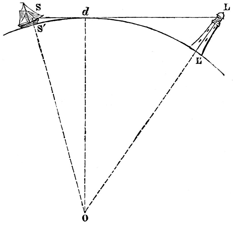
Referring to the accompanying figure (No. 92), in which S′ d L′ is a segment of the ocean’s surface, O the centre of the earth, L′L a Lighthouse, and S the position of the mariner’s eye, we obtain the value of LL′ = H′, the height of the tower in feet by the formula,
H′ = 2 l² 3 (1.)
in which l = the distance in English miles L′d at which the light would strike the ocean’s surface. We then reduce this value of H′ by the correction for mean refraction, which permits the light to be seen at a greater distance, and which =
2 l² 21, (2.)
So as to get, H = 2 l²3 - 2 l²21 = 4 l²7 (3.)
an expression which at once gives the height of the tower required, if the eye of the mariner were just on the surface of the water at d, where the tangent between his eye at S and the light at L would touch the sea. We must, therefore, in the first instance, find the distance d S = l′, which is the radius of the visible horizon due to the height SS′ = h of his eye above the water, and is, of course, at once obtained conversely by the expression:—
l′ = √7 h 2 (4.)
Deducting this distance from SL, the whole effective range of the light, we have L d = l, and operating with this value in the former equation,
H = 4 l²7
we find the height of the tower which answers the conditions of the case.[81] From the above data the following Table has been computed.
H λ λ′ H λ λ′ H λ λ′
Heights in Feet. Lengths in English Miles. Lengths in Nautical Miles. Heights in Feet. Lengths in English Miles. Lengths in Nautical Miles. Heights in Feet. Lengths in English Miles. Lengths in Nautical Miles.
5 2·958 2·565 70 11·067 9·598 250 20·916 18·14
10 4·184 3·628 75 11·456 9·935 300 22·912 19·87
15 5·123 4·443 80 11·832 10·26 350 24·748 21·46
20 5·916 5·130 85 12·196 10·57 400 26·457 22·94
25 6·614 5·736 90 12·549 10·88 450 28·062 24·33
30 7·245 6·283 95 12·893 11·18 500 29·580 25·65
35 7·826 6·787 100 13·228 11·47 550 31·024 26·90
40 8·366 7·255 110 13·874 12·03 600 32·403 28·10
45 8·874 7·696 120 14·490 12·56 650 33·726 29·25
50 9·354 8·112 130 15·083 13·08 700 35·000 30·28
55 9·811 8·509 140 15·652 13·57 800 37·416 32·45
60 10·246 8·886 150 17·201 14·91 900 39·836 34·54
65 10·665 9·249 200 18·708 16·22 1000 41·833 36·28
If the distance at which a light of given height can be seen by a person on a given level be required, it is only needful to add together the two numbers in the column of lengths λ or λ′ (according as Nautical or English miles may be sought) corresponding to those in the column of heights H, which represent respectively the height of the observer’s eye and the height of the lantern above the sea. When the height required to render a light visible at a given distance is required, we must seek first for the number in λ or λ′ corresponding to the height of the observer’s eye, and deduct this from the whole proposed range of the light, and opposite the remainder in λ or λ′ seek for the corresponding number in H.
A considerable practical defect in all the lighthouse lanterns which I have ever seen, with the exception of those recently constructed for the Scotch Lighthouses, consists in the vertical direction of the astragals, which, of course, tend to intercept the whole or a great part of the light in the azimuth which they subtend.[82] The consideration of the improvement which I had effected in giving a Diagonal Lantern. diagonal direction to the joints of the fixed refractors, first led me (as stated at p. 266, ante), to adopt a diagonal arrangement of the framework which carries the cupola of zones and afterwards for the astragals of the lantern. Not only is this direction of the astragals more advantageous for equalising the effect of the light; but the greater stiffness and strength which this arrangement gives to the frame-work of the lantern make it safe to use more slender bars and thus also absolutely less light is intercepted. The panes of glass at the same time become triangular, and are necessarily stronger than rectangular panes of equal surface. This form of lantern is extremely light and elegant, and is shewn, with detailed drawings of some of its principal parts, in Plate XXVI. To avoid the necessity of painting, which, in situations so exposed as those which lighthouses generally occupy, is attended with many inconveniences and no small risk, the framework of the lantern is now formed of gun-metal and the dome is of copper; so that a first order lantern of 12 feet diameter and 10 feet height of glass costs, when glazed, about L.1260. In order to give the lightkeepers free access to cleanse and wash the upper panes of the lantern (an operation which in snowy weather must sometimes be frequently repeated during the night), a narrow gangway, on which they may safely stand, is placed on the level of the top of the lower panes, and at the top of the second panes, rings are provided of which the lightkeepers may lay hold for security in stormy weather. A light trap-ladder is also attached to the outside of the lantern by means of which there is an easy access to the ventilator on the dome.
Glazing of the Lantern. Great care is bestowed on the glazing of the lantern, in order that it may be quite impervious to water, even during the heaviest gales. When iron is used for the frames, they are carefully and frequently painted; but gun-metal, as just noticed, is now generally used in the Scotch Lighthouses. There is great risk of the glass plates being broken by the shaking of the lantern during high winds; and as much as possible to prevent this, various precautions are adopted. The arris of each plate is always carefully rounded by grinding; and grooves about ¹⁄₂ inch wide, capable of holding a good thickness of putty, are provided in the astragals for receiving the glass, which is ¹⁄₄ inch thick. Small pieces of lead or wood are inserted between the frames and the plates of glass against which they may press, and by which they are completely separated from the more unyielding material of which the lantern-frames are composed. Panes glazed in frames padded with cushions, and capable of being temporarily fixed in a few minutes, in the room of a broken plate, are kept ready for use in the Store-room. Those framed plates are called storm-panes, and have been found very useful on several occasions, when the glass has been shattered by large sea-birds coming against it in a stormy night, or by small stones violently driven against the lantern by the force of the wind.
Ventilation of the Lanterns. The ventilation of the lanterns forms a most important element in the preservation of a good and efficient light. An ill-ventilated lantern has its sides continually covered with the water of condensation, which is produced by the contact of the ascending current of heated air; and the glass thus obscured obstructs the passage of the rays, and diminishes the power of the light. In the Northern Lighthouses, ventilators, capable of being opened and shut at pleasure, so as to admit from without a supply of air when required, are provided in the parapet-wall on which the lantern stands; the lantern roof also is surmounted by a cover which, while it closes the top of an open cylindric tube against the entrance of rain, and descends over it only so far as is needful for that purpose, still leaves an open air-space between it and the dome. This arrangement permits the current of heated air, which is continually flowing from the lantern through the cylindric tube, to pass between it and the outer cover, from which it finally escapes to the open air through the space between the cover and the dome. The door which communicates from the lightroom through the parapet to the balcony outside, is also made the means of ventilating the lightroom; and, for that purpose, it is provided with a sliding bolt at the bottom, which, being dropped into one or other of the holes cut in the balcony for its reception, serves to keep the door open at any angle that may be found necessary. A useful precaution was introduced by my predecessor, as Engineer to the Northern Lights Board, in order to prevent the too rapid condensation of heated air on the large internal surface of the lantern roof, which consists in having two domes with an air-space between them, as shewn in the enlarged diagrams in Plate XXVI.
An important improvement in the ventilation of Lighthouses was some years ago introduced by Dr Faraday into several of the Lighthouses belonging to the Trinity House, and has since been adopted in all the dioptric lights belonging to the Commissioners of Northern Lighthouses. After mentioning several proofs of extremely bad ventilation in Lighthouses, Dr Faraday thus describes his apparatus:[83]
“The ventilating pipe or chimney is a copper tube, 4 inches in diameter, not, however, in one length, but divided into three or four pieces; the lower end of each of these pieces for about 1¹⁄₂ inch is opened out into a conical form, about 5¹⁄₂ inches in diameter at the lowest part. When the chimney is put together, the upper end of the bottom piece is inserted about ¹⁄₂ inch into the cone of the next piece above, and fixed there by three ties or pins, so that the two pieces are firmly held together; but there is still plenty of air-way or entrance into the chimney between them. The same arrangement holds good with each succeeding piece. When the ventilating chimney is fixed in its place, it is adjusted so that the lamp-chimney enters about ¹⁄₂ inch into the lower cone, and the top of the ventilating chimney enters into the cowl or head of the lantern.
“With this arrangement, it is found that the action of the ventilating flue is to carry up every portion of the products of combustion into the cowl; none passes by the cone apertures out of the flue into the air of the lantern, but a portion of the air passes from the lantern by these apertures into the flue, and so the lantern itself is in some degree ventilated.
“The important use of these cone apertures is that when a sudden gust or eddy of wind strikes into the cowl of the lantern, it should not have any effect in disturbing or altering the flame. It is found that the wind may blow suddenly in at the cowl, and the effect never reaches the lamp. The upper, or the second, or the third, or even the fourth portion of the ventilating flue might be entirely closed, yet without altering the flame. The cone junctions in no way interfere with the tube in carrying up all the products of combustion; but if any downward current occurs, they dispose of the whole of it into the room without ever affecting the lamp. The ventilating flue is in fact a tube, which, as regards the lamp, can carry everything up but conveys nothing down.”
The advantages of this arrangement, as applied to the Northern Lighthouses, were much less palpable than those which are described in the beginning of Dr Faraday’s paper, because their ventilation was very good before its introduction; and the flame in particular was perfectly steady, being by no means subject to derangement from sudden gusts of wind from the roof in the manner noticed above.
Arrangements and internal management of a Lighthouse. All the Lighthouses in the district of the Commissioners are under the charge of at least two Lightkeepers, whose duties are to cleanse and prepare the apparatus for the night illumination, to mount guard singly after the light is exhibited, and to relieve each other at stated hours, fixed by the printed regulations and instructions, under which they act. The rule is, that no keeper on watch shall, under any circumstances, leave the Lightroom until relieved by his comrade; and, for the purpose of cutting off all pretext for the neglect of this universal law, the dwelling-houses are built close to the Light Tower, and means are provided for making signals directly from the Lightroom to the sleeping apartments below. These signals are communicated by air-tubes, through which, by means of a small piston, or a puff of wind from the mouth, calls can be exchanged between the keepers, enabling the man on guard in the Lightroom, at the end of the watch, or on any sudden emergence, to summon his comrade from below, who, on being thus called, answers by a counter-blast, to shew that the summons has been heard and will be obeyed. For the purpose of greater security, in such situations as the Bell Rock and the Skerryvore, four keepers are provided for one lightroom; one being always ashore on leave with his family, and the other three being at the Lighthouse, so that, in case of the illness of one lightkeeper, an efficient establishment of two keepers for watching the light may remain. At all the land-lighthouses also, an agreement is made with some steady person residing in the neighbourhood, who is instructed in the management of the light and cleansing of the apparatus, and comes under an obligation to be ready to do duty in the light-room when called upon, in the event of the sickness or absence of one of the lightkeepers. This person is called the occasional keeper, and receives pay only while actually employed at the Lighthouse; but in order to keep him in the practice of the duty, he is required to serve in the lightroom for a fortnight annually in the month of January. The details of the lightkeeper’s duty may be seen by referring to the instructions already alluded to, which will be found in the Appendix.
Each of the two lightkeepers has a house for himself and family, both being under a common roof, but entering by separate doors, as shewn in Plates XXVII. and XXVIII., which exhibit the buildings for the new Lighthouse at Ardnamurchan Point, on the coast of Argyllshire. The principal keeper’s house consists of six rooms, two of which are at the disposal of the visiting officers of the Board, whose duty in inspecting the Lighthouse, or superintending repairs, may call them to the station; and the assistant has four rooms, one of which is used as a barrack-room for the workmen, who, under the direction of the Foreman of the lightroom works, execute the annual repairs of the apparatus.
The early Lighthouses contained accommodation for the lightkeepers in the Tower itself; but the dust caused by the cleaning of those rooms in the Tower was found to be very injurious to the delicate apparatus and machinery in the lightroom. Unless, therefore, in situations such as Skerryvore, where it is unavoidable, the dwellings of the lightkeepers ought not to be placed in the Light Tower, but in an adjoining building.
Great care should be bestowed to produce the utmost cleanliness in everything connected with a Lighthouse, the optical apparatus of which is of such a nature as to suffer materially from the effect of dust in injuring its polish. For this purpose covered ash-pits are provided at all the dwelling-houses, in order that the dust of the fire-places may not be carried by the wind to the lightroom; and for similar reasons, iron floors are used for the lightrooms instead of stone, which is often liable to abrasion, and all the stonework near the lantern is regularly painted in oil.
If, in all that belongs to a lighthouse, the greatest cleanliness be desirable, it is in a still higher degree necessary in every part of the lightroom apparatus, without which the optical instruments and the machinery will neither last long nor work well. Cleansing of Apparatus. Every part of the apparatus, whether lenses or reflectors, should be carefully freed from dust before being either washed or burnished; and without such a precaution, the cleansing process would only serve to scratch them. For burnishing the reflectors, prepared rouge (tritoxide of iron) of the finest description, which should be in the state of an impalpable powder of a deep orange-red colour, is applied, by means of soft chamois skins, as occasion may require; but the great art of keeping reflectors clean consists in the daily, patient, and skilful application of manual labour in rubbing the surface of the instrument with a perfectly dry, soft, and clean skin, without rouge. The form of the hollow paraboloid is such, that some practice is necessary in order to acquire a free movement of the hand in rubbing reflectors; and its attainment forms one of the principal lessons in the course of the preliminary instruction, to which candidates for the situation of a light-keeper are subjected at the Bell Rock Lighthouse. For cleansing the lenses and glass mirrors, spirit of wine is used. Having washed the surface of the instrument with a linen cloth steeped in spirit of wine, it is carefully dried with a soft and dry linen rubber, and finally rubbed with a fine chamois skin, free from any dust which would injure the polish of the glass, as well as from grease. It is sometimes necessary to use a little fine rouge with a chamois skin, for restoring any deficiency of polish which may occur from time to time; but in a well-managed lighthouse this application will seldom, if ever, be required.
The machinery of all kinds, whether that of the mechanical lamp or the revolving apparatus, should also be kept scrupulously clean, and all the journals should be carefully oiled.
Mode of measuring the relative intensity and power of Lights. As I have had frequent occasion to speak of the comparative power of lights, it will not be out of place to present the reader with a few practical observations, chiefly drawn from the excellent work of M. Peclet to which I have so often referred, on the measurement of the intensity of lights by the method of shadows.
Fig. 93.
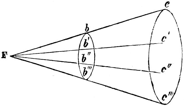
The intensity of light decreases as the observer recedes from the luminous body, in proportion to the square of his distance. Suppose a beam of light to proceed from a radiant at F, and we shall have the rays which, of course, move in straight lines, gradually receding from each other, as b, b′, b″, b‴, and c, c′, c″, c‴, so that the section of the beam will increase with the distances F b, and F c; and the same number of rays, being thus spread over spaces continually increasing, will illuminate the surfaces with a less intensity. This decrease of intensity will, therefore, be in the inverse ratio of the extent of the transverse parallel sections of the luminous cones at b and c, which, we know, increase as the square of their distances from the apex of the cone at F. Hence we conclude, that the intensity of any section of a divergent beam of light decreases as the square of its distance from the radiant. This law furnishes us with a simple measure of the comparative intensity of lights. If we suppose two lights so placed that they may separately illuminate adjacent portions of a vertical screen of paper, we may, by repeatedly comparing the luminousness of those surfaces, and moving one of the lights farther from, or nearer to the screen, at length cause the separate portions of the paper to become equally luminous. This arrangement, however, has many practical difficulties, which I shall not wait to specify; but shall at once indicate a more simple and equally correct mode of obtaining the same result, by means of the shadows cast by the lights from an opaque rod, in a vertical position at O (fig. 94), placed between them, and a screen covered with white paper on which the shadows fall. It is obvious that the light at F would cause the object O to cast a shadow at SS, while the light at F′ would cast a shadow at S′S′. But while the shadow at S would still receive light from F′, S′ would receive light from F, so that those two shadows are, in fact, the only portions of the screen which are each illuminated only by one of the lights, while every other portion of its surface receives light from both the radiants at F and F′. If we suppose F to be the weaker light, we can bring it nearer the screen, until the shadow S′S′, shall become similar in appearance to the shadow SS; and we shall have the ratio of the intensity of the light at F to that of the light at F′, as (FS′)² is to (F′S)², which distances must be measured with the greatest exactness. Such is the mode commonly used in estimating the comparative intensities of two lights; but there are various precautions which are needful in order to prevent errors in comparing the deepness of the shadows, and to insure the greatest attainable accuracy in the estimate of the power of the lights, which I shall endeavour briefly to describe.