Note 62 — PART SECOND. NOTES ON THE ILLUMINATION OF LIGHTHOUSES, WITH SHORT NOTICES OF THEIR EARLY HISTORY. (continued 2)
Reading edition
To find the radius and centre of a circle, which shall osculate a given parabola, whose focus is in F, draw the normals to the curve from p and P, meeting in O, and draw N e parallel to a tangent of the curve, or to p P, then P O or p O is the radius required. Now, we have similar triangles P p d and N e n, and P H and p h are (proximate) ordinates; hence we have the following analogies:—
P d ∶ P p ∷ PH ∶ PN
N e ∶ N n ∷ PH ∶ PN
Fig. 66.
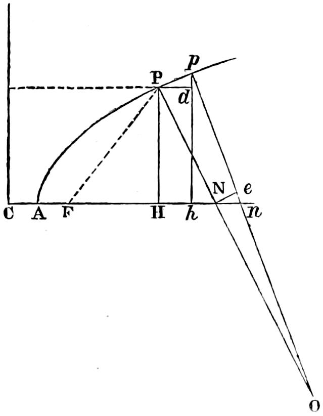
Hence compounding those ratios (in which P d = N n nearly)
N e ∶ P p ∷ PH² ∶ PN²
also N e ∶ P p ∷ NO ∶ PO,
(for O P p and N o e are similar triangles)
PH² ∶ PN² ∷ NO ∶ OP,
then PN²- PH² = HN²
and PO - NO = NP,
therefore HN² ∶ PN² ∷ NP ∶ PO,
and finally, PO = PN³ HN².
Then put FP = HC = FN = ρ; HN = ρ - z; then as FP² - FH² = PH² = ρ² - z²
PN² = PH² + HN² = (ρ² - z²) + (ρ² - 2 ρ z + z²)
= 2ρ² - 2 ρ z
PN = √2 ρ (ρ - z)
Therefore PO = √{2 ρ (ρ - z)}³ (ρ - z)²
= √{2 ρ (ρ - z)}³ (ρ - z)⁴
and finally, PO = 2√2 √ρ³ ρ - z
Fig. 67.
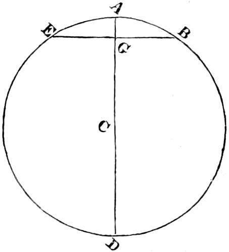
To find the versed sine of the curvature (which may be useful in the examination of the mirrors by a mould) we may proceed (see fig. 67) to
put AG = f; BE = C; AC = R then BG² = AG . GD 4 BG² = BE² = 4 AG . GD C² = 4 f . (2 R - f) C² = 8 f R - 4 f²
From which equation,
2 f - 2 R = ± √4 R² - C² = -2 R + C²4 R - C⁴64 R³ &c. 2 f = C²4 R - C⁴64 R³ f = C²8 R - C⁴128 R³.
Fig. 68.
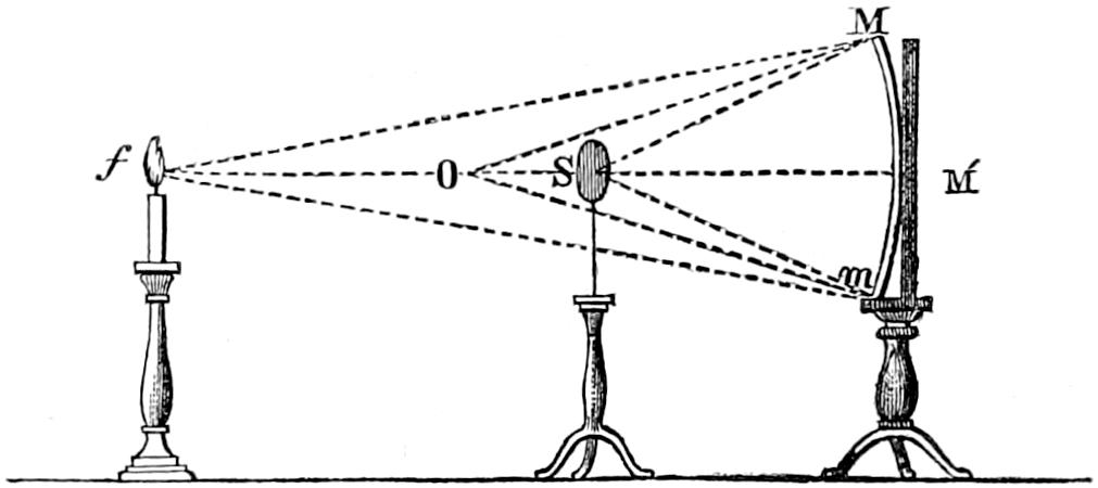
In order to test the accuracy of the workmanship of the mirrors, recourse must again be had, as in the case of the lenses and parabolic mirrors, to the formula of conjugate foci, in which we shall call R = the radius of curvature of the mirror M m (fig. 68); a = the distance of a light, f, which is arbitrarily placed in front of the mirror; and b = the distance of a moveable screen S, on which the rays reflected from the mirror may converge in a focus. We must find the distance b, at which, with any given distance a, such convergence should take place.
f M′ = a
SM′ = b
OM′ = R
Then (because f MS is bisected by OM, and for points near the vertex of the mirror at M′)
SM′ ∶ f M′ ∷ SO ∶ O f
or b ∶ a ∷ R - b ∶ a - R
a b - R a = R b - a b.
From which b = R a 2 a - R, the distance required, in which an error of ¹⁄₃₀ (of its whole length) may be safely admitted.
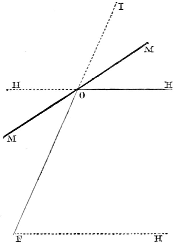
[63] At such times when the horizon cannot be seen, the mirror may be placed, by means of a clinometer, with a spirit-level, set to the proper angle, which may be easily mechanically determined as follows: Draw a line from the focus F through the point O, where the centre of the mirror is to be, producing it beyond that point to a convenient distance at I; through O draw HOH, parallel to the horizon FH; bisect IOH by MOM, which coincides with a tangent to the mirror at its centre O; and MOH is the angle required to be laid off, or its complement.
Fig. 69.