II.
Reading edition
II.
DEMONSTRATIONS WHICH COULD NOT CONVENIENTLY BE INCLUDED IN THE TEXT.
I.
THE SECOND COROLLARY, PROBLEM II.
In Fig. 8. omit the lines C D, C′ D′, and D S; and, as here in Fig. 75., from a draw a d parallel to A B, cutting B T in d; and from d draw d e parallel to B C′.
Fig. 75.
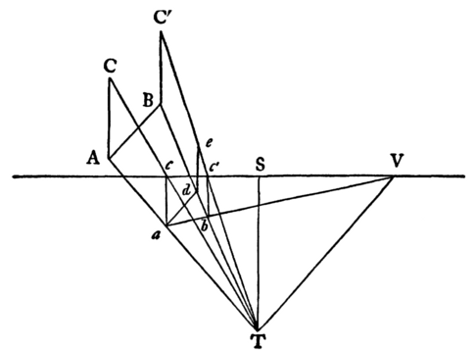
Now as a d is parallel to A B—
A C ∶
a c
∷ B C′
d e
;
[
eqn
iii]
but A C is equal to B C′—
∴
a c
=
d e
.
Now because the triangles a c V, b c′ V, are similar—
a c
∶
b c′
∷
a
V ∶
b
V
;
[
eqn
iv]
and because the triangles d e T, b c′ T are similar—
d e
∶
b c′
∷
d
T ∶
b
T
.
[
eqn
v]
But a c is equal to d e—
∴
a
V ∶
b
V ∷
d
T ∶
b
T
[
eqn
vi]
;
∴ the two triangles a b d, b T V, are similar, and their angles are alternate;
∴ T V
is parallel to
a d
.
But a d is parallel to A B—
∴ T V is parallel to A B.
II.
THE THIRD COROLLARY, PROBLEM III.
In Fig. 13., since a R is by construction parallel to A B in Fig. 12., and T V is by construction in Problem III. also parallel to A B—
∴ a R is parallel to T V, ∴ a b R and T b V are alternate triangles, ∴ a R ∶ T V ∷ a b ∶ b V[eqn vii].
Again, by the construction of Fig. 13., a R′ is parallel to M V—
∴ a b R′ and M b V are alternate triangles, ∴ a R′ ∶ M V ∷ a b ∶ b V[eqn viii].
And it has just been shown that also
a R ∶ T V ∷ a b ∶ b V— ∴ a R′ ∶ M V ∷ a R ∶ T V[eqn ix].
But by construction, a R′ = a R—
∴ M V = T V.
III.
ANALYSIS OF PROBLEM XV.
We proceed to take up the general condition of the second problem, before left unexamined, namely, that in which the vertical distances B C′ and A C (Fig. 6. page 13), as well as the direct distances T D and T D′ are unequal.
In Fig. 6., here repeated (Fig. 76.), produce C′ B downwards, and make C′ E equal to C A.
Fig. 76.
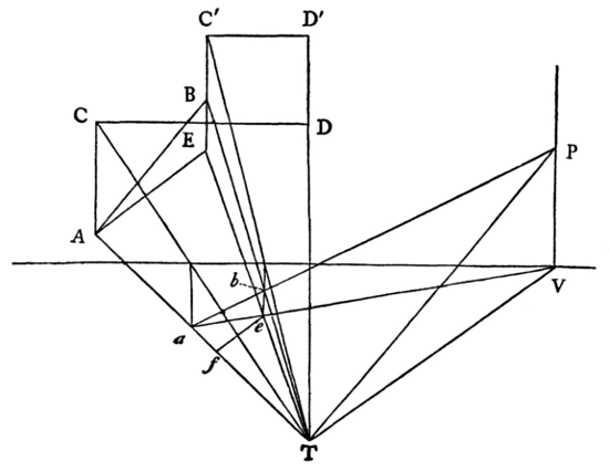
Join A E.
Then, by the second Corollary of Problem II., A E is a horizontal line.
Draw T V parallel to A E, cutting the sight-line in V.
∴ V is the vanishing-point of A E.
Complete the constructions of Problem II. and its second Corollary.
Then by Problem II. a b is the line A B drawn in perspective; and by its Corollary a e is the line A E drawn in perspective.
From V erect perpendicular V P, and produce a b to cut it in P.
Join T P, and from e draw e f parallel to A E, and cutting A T in f.
Now in triangles E B T and A E T, as e b is parallel to E B and e f to A E;—e b ∶ e f ∷ E B ∶ A E[eqn x].
But T V is also parallel to A E and P V to e b.
Therefore also in the triangles a P V and a V T,
e b ∶ e f ∷ P V ∶ V T[eqn xi].
Therefore P V ∶ V T ∷ E B ∶ A E[eqn xii].
And, by construction, angle T P V = ∠ A E B.
Therefore the triangles T V P, A E B, are similar; and T P is parallel to A B.
Now the construction in this problem is entirely general for any inclined line A B, and a horizontal line A E in the same vertical plane with it.
So that if we find the vanishing-point of A E in V, and from V erect a vertical V P, and from T draw T P parallel to A B, cutting V P in P, P will be the vanishing-point of A B, and (by the same proof as that given at page 17) of all lines parallel to it.
Fig. 77.
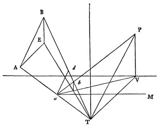
Next, to find the dividing-point of the inclined line.
I remove some unnecessary lines from the last figure and repeat it here, Fig. 77., adding the measuring-line a M, that the student may observe its position with respect to the other lines before I remove any more of them.
Now if the line A B in this diagram represented the length of the line A B in reality (as A B does in Figs. 10. and 11.), we should only have to proceed to modify Corollary III. of Problem II. to this new construction. We shall see presently that A B does not represent the actual length of the inclined line A B in nature, nevertheless we shall first proceed as if it did, and modify our result afterwards.
In Fig. 77. draw a d parallel to A B, cutting B T in d.
Therefore a d is the sight-magnitude of A B, as a R is of A B in Fig. 11.
Fig. 78.
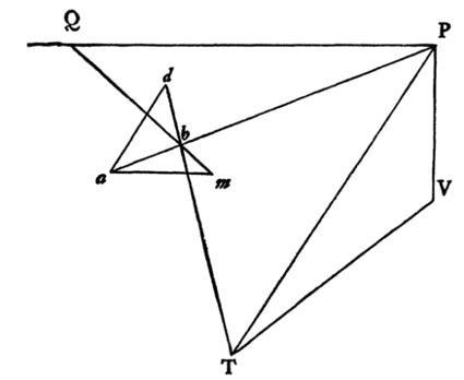
Remove again from the figure all lines except P V, V T, P T, a b, a d, and the measuring-line.
Set off on the measuring-line a m equal to a d.
Draw P Q parallel to a m, and through b draw m Q, cutting P Q in Q.
Then, by the proof already given in page 20, P Q = P T.
Therefore if P is the vanishing-point of an inclined line A B, and Q P is a horizontal line drawn through it, make P Q equal to P T, and a m on the measuring-line equal to the sight-magnitude of the line A B in the diagram, and the line joining m Q will cut a P in b.
We have now, therefore, to consider what relation the length of the line A B in this diagram, Fig. 77., has to the length of the line A B in reality.
Now the line A E in Fig. 77. represents the length of A E in reality.
But the angle A E B, Fig. 77., and the corresponding angle in all the constructions of the earlier problems, is in reality a right angle, though in the diagram necessarily represented as obtuse.
Fig. 79.
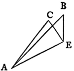
Therefore, if from E we draw E C, as in Fig. 79., at right angles to A E, make E C = E B, and join A C, A C will be the real length of the line A B.
Now, therefore, if instead of a m in Fig. 78., we take the real length of A B, that real length will be to a m as A C to A B in Fig. 79.
And then, if the line drawn to the measuring-line P Q is still to cut a P in b, it is evident that the line P Q must be shortened in the same ratio that a m was shortened; and the true dividing-point will be Q′ in Fig. 80., fixed so that Q′ PQ P as a m′ is to a m; a m′ representing the real length of A B.
But a m′ is therefore to a m as A C is to A B in Fig. 79.
Therefore P Q′ must be to P Q as A C is to A B.
But P Q equals P T (Fig. 78.); and P V is to V T (in Fig. 78.) as B E is to A E (Fig. 79.).
Hence we have only to substitute P V for E C, and V T for A E, in Fig. 79., and the resulting diagonal A C will be the required length of P Q′.
Fig. 80.
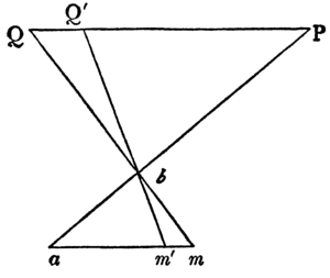
It will be seen that the construction given in the text (Fig. 46.) is the simplest means of obtaining this magnitude, for V D in Fig. 46. (or V M in Fig. 15.) = V T by construction in Problem IV. It should, however, be observed, that the distance P Q′ or P X, in Fig. 46., may be laid on the sight-line of the inclined plane itself, if the measuring-line be drawn parallel to that sight-line. And thus any form may be drawn on an inclined plane as conveniently as on a horizontal one, with the single exception of the radiation of the verticals, which have a vanishing-point, as shown in Problem XX.
THE END.