VOLUME VIII SLICE IV Diameter to Dinarchus (continued 9)
Reading edition
In many cases the subject of examination is a luminous line of uniform intensity, the various points of which are to be treated as independent sources of light. If the image of the line be ξ = 0, the intensity at any point ξ, η of the diffraction pattern may be represented by
sin² πaξ (8),
∫ +∞ I²dη = a²b λf
−∞ λƒ π²a²ξ²
λ²f²
the same law as obtains for a luminous point when horizontal directions are alone considered. The definition of a fine vertical line, and consequently the resolving power for contiguous vertical lines, is thus independent of the vertical aperture of the instrument, a law of great importance in the theory of the spectroscope.
The distribution of illumination in the image of a luminous line is shown by the curve ABC (fig. 3), representing the value of the function sin²u/u² from u = 0 to u = 2π. The part corresponding to negative values of u is similar, OA being a line of symmetry.
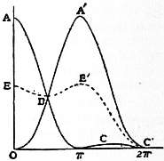
Fig. 3.
Let us now consider the distribution of brightness in the image of a double line whose components are of equal strength, and at such an angular interval that the central line in the image of one coincides with the first zero of brightness in the image of the other. In fig. 3 the curve of brightness for one component is ABC, and for the other OA′C′; and the curve representing half the combined brightnesses is E′BE. The brightness (corresponding to B) midway between the two central points AA’ is .8106 of the brightness at the central points themselves. We may consider this to be about the limit of closeness at which there could be any decided appearance of resolution, though doubtless an observer accustomed to his instrument would recognize the duplicity with certainty. The obliquity, corresponding to u = π, is such that the phases of the secondary waves range over a complete period, i.e. such that the projection of the horizontal aperture upon this direction is one wave-length. We conclude that a double line cannot be fairly resolved unless its components subtend an angle exceeding that subtended by the wave-length of light at a distance equal to the horizontal aperture. This rule is convenient on account of its simplicity; and it is sufficiently accurate in view of the necessary uncertainty as to what exactly is meant by resolution.
If the angular interval between the components of a double line be half as great again as that supposed in the figure, the brightness midway between is .1802 as against 1.0450 at the central lines of each image. Such a falling off in the middle must be more than sufficient for resolution. If the angle subtended by the components of a double line be twice that subtended by the wave-length at a distance equal to the horizontal aperture, the central bands are just clear of one another, and there is a line of absolute blackness in the middle of the combined images.
The resolving power of a telescope with circular or rectangular aperture is easily investigated experimentally. The best object for examination is a grating of fine wires, about fifty to the inch, backed by a sodium flame. The object-glass is provided with diaphragms pierced with round holes or slits. One of these, of width equal, say, to one-tenth of an inch, is inserted in front of the object-glass, and the telescope, carefully focused all the while, is drawn gradually back from the grating until the lines are no longer seen. From a measurement of the maximum distance the least angle between consecutive lines consistent with resolution may be deduced, and a comparison made with the rule stated above.
Merely to show the dependence of resolving power on aperture it is not necessary to use a telescope at all. It is sufficient to look at wire gauze backed by the sky or by a flame, through a piece of blackened cardboard, pierced by a needle and held close to the eye. By varying the distance the point is easily found at which resolution ceases; and the observation is as sharp as with a telescope. The function of the telescope is in fact to allow the use of a wider, and therefore more easily measurable, aperture. An interesting modification of the experiment may be made by using light of various wave-lengths.
Since the limitation of the width of the central band in the image of a luminous line depends upon discrepancies of phase among the secondary waves, and since the discrepancy is greatest for the waves which come from the edges of the aperture, the question arises how far the operation of the central parts of the aperture is advantageous. If we imagine the aperture reduced to two equal narrow slits bordering its edges, compensation will evidently be complete when the projection on an oblique direction is equal to ½λ, instead of λ as for the complete aperture. By this procedure the width of the central band in the diffraction pattern is halved, and so far an advantage is attained. But, as will be evident, the bright bands bordering the central band are now not inferior to it in brightness; in fact, a band similar to the central band is reproduced an indefinite number of times, so long as there is no sensible discrepancy of phase in the secondary waves proceeding from the various parts of the same slit. Under these circumstances the narrowing of the band is paid for at a ruinous price, and the arrangement must be condemned altogether.
A more moderate suppression of the central parts is, however, sometimes advantageous. Theory and experiment alike prove that a double line, of which the components are equally strong, is better resolved when, for example, one-sixth of the horizontal aperture is blocked off by a central screen; or the rays quite at the centre may be allowed to pass, while others a little farther removed are blocked off. Stops, each occupying one-eighth of the width, and with centres situated at the points of trisection, answer well the required purpose.
It has already been suggested that the principle of energy requires that the general expression for I² in (2) when integrated over the whole of the plane ξ, η should be equal to A, where A is the area of the aperture. A general analytical verification has been given by Sir G. G. Stokes (Edin. Trans., 1853, 20, p. 317). Analytically expressed—
∫∫ +∞ I² dξdη = ∫∫ dxdy = A (9).
−∞
We have seen that I0² (the intensity at the focal point) was equal to A²/λ²f². If A′ be the area over which the intensity must be I0² in order to give the actual total intensity in accordance with
A′ I0² = ∫∫ +∞ I² dξdη,
−∞
the relation between A and A′ is AA′ = λ²f². Since A′ is in some sense the area of the diffraction pattern, it may be considered to be a rough criterion of the definition, and we infer that the definition of a point depends principally upon the area of the aperture, and only in a very secondary degree upon the shape when the area is maintained constant.
4. Theory of Circular Aperture.—We will now consider the important case where the form of the aperture is circular.
Writing for brevity
kξ/f = p, kη/f = q, (1),
we have for the general expression (§ 11) of the intensity
λ²f²I² = S² + C² (2),
where
S = ∫∫ sin(px + qy)dx dy, (3),
C = ∫∫ cos(px + qy)dx dy, (4).
When, as in the application to rectangular or circular apertures, the form is symmetrical with respect to the axes both of x and y, S = 0, and C reduces to
C = ∫∫ cos px cos qy dx dy, (5).
In the case of the circular aperture the distribution of light is of course symmetrical with respect to the focal point p = 0, q = 0; and C is a function of p and q only through √(p² + q²). It is thus sufficient to determine the intensity along the axis of p. Putting q = 0, we get
C = ∫∫ cos px dx dy = 2 ∫ +R cos px √(R² − x²) dx,
−R
R being the radius of the aperture. This integral is the Bessel’s function of order unity, defined by
J1(z) = z ∫ π cos (z cos φ) sin² φ dφ (6).
π 0
Thus, if x = R cos φ,
C = π²R 2J1(pR) (7);
pR
and the illumination at distance r from the focal point is
· 4J1² ( 2πRr ) (8).
I² = π²R4 ƒλ
λ²f² ( 2πRr ) ²
ƒλ
The ascending series for J1(z), used by Sir G. B. Airy (Camb. Trans., 1834) in his original investigation of the diffraction of a circular object-glass, and readily obtained from (6), is
J1(z) = z − z³ + z5 − z7 + ... (9).
2 2²·4 2²·4²·6 2²·4²·6²·8
When z is great, we may employ the semi-convergent series
J1(z) = √( 2 ) sin (z − ¼π) { 1 + 3·5·1 ( 1 ) ² − 3·5·7·9·1·3·5 ( 1 ) 4 + ... }
πz 8·16 z 8·16·24·32 z
+ √( 2 ) cos (z − ¼π) {3/8 · 1/z − 3·5·7·1·3 ( 1 ) ³ + 3·5·7·9·11·1·3·5·7 ( 1 ) 5 − ... } (10).
πz 8·16·24 z 8·16·24·32·40 z
A table of the values of 2z-1J1(z) has been given by E. C. J. Lommel (Schlömilch, 1870, 15, p. 166), to whom is due the first systematic application of Bessel’s functions to the diffraction integrals.
The illumination vanishes in correspondence with the roots of the equation J1(z) = 0. If these be called z1 z2, z3, ... the radii of the dark rings in the diffraction pattern are
ƒλz1 ƒλz2 , ...
2πR 2πR
being thus inversely proportional to R.
The integrations may also be effected by means of polar co-ordinates, taking first the integration with respect to φ so as to obtain the result for an infinitely thin annular aperture. Thus, if
x = ρ cos φ, y = ρ sin φ,
C = ∫∫ cos px dx dy = ∫ R ∫ 2π cos (pρ cos θ) ρdρ dθ.
0 0
Now by definition
J0(z) = 2 ∫ ½π cos (z cos θ) dθ = 1 − z² + z4 − z6 + ... (11).
π 0 2² 2²·4² 2²·4²·6²
The value of C for an annular aperture of radius r and width dr is thus
dC = 2 π J0 (pρ) ρ dρ, (12).
For the complete circle,
C = 2π ∫ pr J0(z) zdz = 2π { p²R² − p4R4 + p6R6 − ...}= πR² · 2J1(pR) as before.
p² 0 p² 2 2²·4² 2²·4²·6² pR
In these expressions we are to replace p by kξ/ƒ, or rather, since the diffraction pattern is symmetrical, by kr/ƒ, where r is the distance of any point in the focal plane from the centre of the system.
The roots of J0(z) after the first may be found from
z = i − .25 + .050561 − .053041 + .262051 (13),
π 4i − 1 (4i − 1)³ (4i − 1)5
and those of J1(z) from
z = i + .25 − .151982 + .015399 − .245835 (14),
π 4i + 1 (4i + 1)³ (4i + 1)5
formulae derived by Stokes (Camb. Trans., 1850, vol. ix.) from the descending series.1 The following table gives the actual values:—
i z/π for J0(z) = 0 z/π for J1(z) = 0
1 7655 1 2197
2 1 7571 2 2330
3 2 7546 3 2383
4 3 7534 4 2411
5 4 7527 5 2428
6 5 7522 6 2439
7 6 7519 7 2448
8 7 7516 8 2454
9 8 7514 9 2459
10 9 7513 10 2463
In both cases the image of a mathematical point is thus a symmetrical ring system. The greatest brightness is at the centre, where
dC = 2πρ dρ, C = π R².
For a certain distance outwards this remains sensibly unimpaired and then gradually diminishes to zero, as the secondary waves become discrepant in phase. The subsequent revivals of brightness forming the bright rings are necessarily of inferior brilliancy as compared with the central disk.
The first dark ring in the diffraction pattern of the complete circular aperture occurs when
r/ƒ = 1.2197 × λ/2R (15).
We may compare this with the corresponding result for a rectangular aperture of width a,
ξ/ƒ =λ/a;
and it appears that in consequence of the preponderance of the central parts, the compensation in the case of the circle does not set in at so small an obliquity as when the circle is replaced by a rectangular aperture, whose side is equal to the diameter of the circle.
Again, if we compare the complete circle with a narrow annular aperture of the same radius, we see that in the latter case the first dark ring occurs at a much smaller obliquity, viz.
r/ƒ = .7655 × λ/2R.
It has been found by Sir William Herschel and others that the definition of a telescope is often improved by stopping off a part of the central area of the object-glass; but the advantage to be obtained in this way is in no case great, and anything like a reduction of the aperture to a narrow annulus is attended by a development of the external luminous rings sufficient to outweigh any improvement due to the diminished diameter of the central area.2
The maximum brightnesses and the places at which they occur are easily determined with the aid of certain properties of the Bessel’s functions. It is known (see Spherical Harmonics) that
J0′(z) = −J1(z), (16);
J2(z) = (1/z) J1(z) − J1′(z) (17);
J0(z) + J2(z) = (2/z) J1(z) (18).
The maxima of C occur when
d ( J1(z) ) = J1′(z) − J1(z) = 0;
dz z z z²
or by 17 when J2(z) = 0. When z has one of the values thus determined,
2J1(z) = J0(z).
z
The accompanying table is given by Lommel, in which the first column gives the roots of J2(z) = 0, and the second and third columns the corresponding values of the functions specified. If appears that the maximum brightness in the first ring is only about 1⁄57 of the brightness at the centre.
z 2z−1J1(z) 4z−2J1²(z)
.000000 +1.000000 1.000000
5.135630 − .132279 .017498
8.417236 + .064482 .004158
11.619857 − .040008 .001601
14.795938 + .027919 .000779
17.959820 − .020905 .000437
We will now investigate the total illumination distributed over the area of the circle of radius r. We have
I² = π²R4 · 4J1²(z) (19),
벃² z²
where
z = 2πRr/λf (20).
Thus
2π ∫ I²rdr = λ²f² ∫ I²zdz = πR²· 2 ∫ z−1J1²(z)dz.
2πR²
Now by (17), (18)
z-1J1(z) = J0(z) − J1′(z);
so that
z-1J1²(z) = − ½ d J0² − ½ d J1²(z),
dz dz
and
2 ∫ z z-1J1²(z)dz = 1 − J0²(z) − J1²(z) (21).
0
If r, or z, be infinite, J0(z), J1(z) vanish, and the whole illumination is expressed by πR², in accordance with the general principle. In any case the proportion of the whole illumination to be found outside the circle of radius r is given by
J0²(z) + J1²(z).
For the dark rings J1(z) = 0; so that the fraction of illumination outside any dark ring is simply J0²(z). Thus for the first, second, third and fourth dark rings we get respectively .161, .090, .062, .047, showing that more than 9⁄10ths of the whole light is concentrated within the area of the second dark ring (Phil. Mag., 1881).
When z is great, the descending series (10) gives
2J1(z) = 2 √( 2 ) sin(z − ¼π) (22);
z z πz
so that the places of maxima and minima occur at equal intervals.
The mean brightness varies as z-3 (or as r-3), and the integral found by multiplying it by zdz and integrating between 0 and ∞ converges.
It may be instructive to contrast this with the case of an infinitely narrow annular aperture, where the brightness is proportional to J0²(z). When z is great,
J0(z) = √( 2 ) cos(z-1/4π).
πz
The mean brightness varies as z-1; and the integral ∫∞0 J0²(z)z dz is not convergent.
5. Resolving Power of Telescopes.—The efficiency of a telescope is of course intimately connected with the size of the disk by which it represents a mathematical point. In estimating theoretically the resolving power on a double star we have to consider the illumination of the field due to the superposition of the two independent images. If the angular interval between the components of a double star were equal to twice that expressed in equation (15) above, the central disks of the diffraction patterns would be just in contact. Under these conditions there is no doubt that the star would appear to be fairly resolved, since the brightness of its external ring system is too small to produce any material confusion, unless indeed the components are of very unequal magnitude. The diminution of the star disks with increasing aperture was observed by Sir William Herschel, and in 1823 Fraunhofer formulated the law of inverse proportionality. In investigations extending over a long series of years, the advantage of a large aperture in separating the components of close double stars was fully examined by W. R. Dawes.
The resolving power of telescopes was investigated also by J. B. L. Foucault, who employed a scale of equal bright and dark alternate parts; it was found to be proportional to the aperture and independent of the focal length. In telescopes of the best construction and of moderate aperture the performance is not sensibly prejudiced by outstanding aberration, and the limit imposed by the finiteness of the waves of light is practically reached. M. E. Verdet has compared Foucault’s results with theory, and has drawn the conclusion that the radius of the visible part of the image of a luminous point was equal to half the radius of the first dark ring.
The application, unaccountably long delayed, of this principle to the microscope by H. L. F. Helmholtz in 1871 is the foundation of the important doctrine of the microscopic limit. It is true that in 1823 Fraunhofer, inspired by his observations upon gratings, had very nearly hit the mark.3 And a little before Helmholtz, E. Abbe published a somewhat more complete investigation, also founded upon the phenomena presented by gratings. But although the argument from gratings is instructive and convenient in some respects, its use has tended to obscure the essential unity of the principle of the limit of resolution whether applied to telescopes or microscopes.
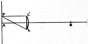
Fig. 4.
In fig. 4, AB represents the axis of an optical instrument (telescope or microscope), A being a point of the object and B a point of the image. By the operation of the object-glass LL′ all the rays issuing from A arrive in the same phase at B. Thus if A be self-luminous, the illumination is a maximum at B, where all the secondary waves agree in phase. B is in fact the centre of the diffraction disk which constitutes the image of A. At neighbouring points the illumination is less, in consequence of the discrepancies of phase which there enter. In like manner if we take a neighbouring point P, also self-luminous, in the plane of the object, the waves which issue from it will arrive at B with phases no longer absolutely concordant, and the discrepancy of phase will increase as the interval AP increases. When the interval is very small the discrepancy, though mathematically existent, produces no practical effect; and the illumination at B due to P is as important as that due to A, the intensities of the two luminous sources being supposed equal. Under these conditions it is clear that A and P are not separated in the image. The question is to what amount must the distance AP be increased in order that the difference of situation may make itself felt in the image. This is necessarily a question of degree; but it does not require detailed calculations in order to show that the discrepancy first becomes conspicuous when the phases corresponding to the various secondary waves which travel from P to B range over a complete period. The illumination at B due to P then becomes comparatively small, indeed for some forms of aperture evanescent. The extreme discrepancy is that between the waves which travel through the outermost parts of the object-glass at L and L′; so that if we adopt the above standard of resolution, the question is where must P be situated in order that the relative retardation of the rays PL and PL’ may on their arrival at B amount to a wave-length (λ). In virtue of the general law that the reduced optical path is stationary in value, this retardation may be calculated without allowance for the different paths pursued on the farther side of L, L′, so that the value is simply PL − PL′. Now since AP is very small, AL′ − PL′ = AP sin α, where α is the angular semi-aperture L′AB. In like manner PL − AL has the same value, so that
PL − PL′ = 2AP sin α.
According to the standard adopted, the condition of resolution is therefore that AP, or ε, should exceed ½λ/sin α. If ε be less than this, the images overlap too much; while if ε greatly exceed the above value the images become unnecessarily separated.
In the above argument the whole space between the object and the lens is supposed to be occupied by matter of one refractive index, and λ represents the wave-length in this medium of the kind of light employed. If the restriction as to uniformity be violated, what we have ultimately to deal with is the wave-length in the medium immediately surrounding the object.
Calling the refractive index μ, we have as the critical value of ε,
ε = ½λ0 /μ sin α, (1),
λ0 being the wave-length in vacuo. The denominator μ sin α is the quantity well known (after Abbe) as the “numerical aperture.”
The extreme value possible for α is a right angle, so that for the microscopic limit we have
ε = ½λ0/μ (2).
The limit can be depressed only by a diminution in λ0, such as photography makes possible, or by an increase in μ, the refractive index of the medium in which the object is situated.
The statement of the law of resolving power has been made in a form appropriate to the microscope, but it admits also of immediate application to the telescope. If 2R be the diameter of the object-glass and D the distance of the object, the angle subtended by AP is ε/D, and the angular resolving power is given by
λ/2D sin α = λ/2R (3).
This method of derivation (substantially due to Helmholtz) makes it obvious that there is no essential difference of principle between the two cases, although the results are conveniently stated in different forms. In the case of the telescope we have to deal with a linear measure of aperture and an angular limit of resolution, whereas in the case of the microscope the limit of resolution is linear, and it is expressed in terms of angular aperture.
It must be understood that the above argument distinctly assumes that the different parts of the object are self-luminous, or at least that the light proceeding from the various points is without phase relations. As has been emphasized by G. J. Stoney, the restriction is often, perhaps usually, violated in the microscope. A different treatment is then necessary, and for some of the problems which arise under this head the method of Abbe is convenient.
The importance of the general conclusions above formulated, as imposing a limit upon our powers of direct observation, can hardly be overestimated; but there has been in some quarters a tendency to ascribe to it a more precise character than it can bear, or even to mistake its meaning altogether. A few words of further explanation may therefore be desirable. The first point to be emphasized is that nothing whatever is said as to the smallness of a single object that may be made visible. The eye, unaided or armed with a telescope, is able to see, as points of light, stars subtending no sensible angle. The visibility of a star is a question of brightness simply, and has nothing to do with resolving power. The latter element enters only when it is a question of recognizing the duplicity of a double star, or of distinguishing detail upon the surface of a planet. So in the microscope there is nothing except lack of light to hinder the visibility of an object however small. But if its dimensions be much less than the half wave-length, it can only be seen as a whole, and its parts cannot be distinctly separated, although in cases near the border line some inference may be possible, founded upon experience of what appearances are presented in various cases. Interesting observations upon particles, ultra-microscopic in the above sense, have been recorded by H. F. W. Siedentopf and R. A. Zsigmondy (Drude’s Ann., 1903, 10, p. 1).
In a somewhat similar way a dark linear interruption in a bright ground may be visible, although its actual width is much inferior to the half wave-length. In illustration of this fact a simple experiment may be mentioned. In front of the naked eye was held a piece of copper foil perforated by a fine needle hole. Observed through this the structure of some wire gauze just disappeared at a distance from the eye equal to 17 in., the gauze containing 46 meshes to the inch. On the other hand, a single wire 0.034 in. in diameter remained fairly visible up to a distance of 20 ft. The ratio between the limiting angles subtended by the periodic structure of the gauze and the diameter of the wire was (.022/.034) × (240/17) = 9.1. For further information upon this subject reference may be made to Phil. Mag., 1896, 42, p. 167; Journ. R. Micr. Soc., 1903, p. 447.
6. Coronas or Glories.—The results of the theory of the diffraction patterns due to circular apertures admit of an interesting application to coronas, such as are often seen encircling the sun and moon. They are due to the interposition of small spherules of water, which act the part of diffracting obstacles. In order to the formation of a well-defined corona it is essential that the particles be exclusively, or preponderatingly, of one size.
If the origin of light be treated as infinitely small, and be seen in focus, whether with the naked eye or with the aid of a telescope, the whole of the light in the absence of obstacles would be concentrated in the immediate neighbourhood of the focus. At other parts of the field the effect is the same, in accordance with the principle known as Babinet’s, whether the imaginary screen in front of the object-glass is generally transparent but studded with a number of opaque circular disks, or is generally opaque but perforated with corresponding apertures. Since at these points the resultant due to the whole aperture is zero, any two portions into which the whole may be divided must give equal and opposite resultants. Consider now the light diffracted in a direction many times more oblique than any with which we should be concerned, were the whole aperture uninterrupted, and take first the effect of a single small aperture. The light in the proposed direction is that determined by the size of the small aperture in accordance with the laws already investigated, and its phase depends upon the position of the aperture. If we take a direction such that the light (of given wave-length) from a single aperture vanishes, the evanescence continues even when the whole series of apertures is brought into contemplation. Hence, whatever else may happen, there must be a system of dark rings formed, the same as from a single small aperture. In directions other than these it is a more delicate question how the partial effects should be compounded. If we make the extreme suppositions of an infinitely small source and absolutely homogeneous light, there is no escape from the conclusion that the light in a definite direction is arbitrary, that is, dependent upon the chance distribution of apertures. If, however, as in practice, the light be heterogeneous, the source of finite area, the obstacles in motion, and the discrimination of different directions imperfect, we are concerned merely with the mean brightness found by varying the arbitrary phase-relations, and this is obtained by simply multiplying the brightness due to a single aperture by the number of apertures (n) (see Interference of Light, § 4). The diffraction pattern is therefore that due to a single aperture, merely brightened n times.
In his experiments upon this subject Fraunhofer employed plates of glass dusted over with lycopodium, or studded with small metallic disks of uniform size; and he found that the diameters of the rings were proportional to the length of the waves and inversely as the diameter of the disks.
In another respect the observations of Fraunhofer appear at first sight to be in disaccord with theory; for his measures of the diameters of the red rings, visible when white light was employed, correspond with the law applicable to dark rings, and not to the different law applicable to the luminous maxima. Verdet has, however, pointed out that the observation in this form is essentially different from that in which homogeneous red light is employed, and that the position of the red rings would correspond to the absence of blue-green light rather than to the greatest abundance of red light. Verdet’s own observations, conducted with great care, fully confirm this view, and exhibit a complete agreement with theory.
By measurements of coronas it is possible to infer the size of the particles to which they are due, an application of considerable interest in the case of natural coronas—the general rule being the larger the corona the smaller the water spherules. Young employed this method not only to determine the diameters of cloud particles (e.g. 1⁄1000 in.), but also those of fibrous material, for which the theory is analogous. His instrument was called the eriometer (see “Chromatics,” vol. iii. of supp. to Ency. Brit., 1817).
7. Influence of Aberration. Optical Power of Instruments.—Our investigations and estimates of resolving power have thus far proceeded upon the supposition that there are no optical imperfections, whether of the nature of a regular aberration or dependent upon irregularities of material and workmanship. In practice there will always be a certain aberration or error of phase, which we may also regard as the deviation of the actual wave-surface from its intended position. In general, we may say that aberration is unimportant when it nowhere (or at any rate over a relatively small area only) exceeds a small fraction of the wave-length (λ). Thus in estimating the intensity at a focal point, where, in the absence of aberration, all the secondary waves would have exactly the same phase, we see that an aberration nowhere exceeding ¼λ can have but little effect.
The only case in which the influence of small aberration upon the entire image has been calculated (Phil. Mag., 1879) is that of a rectangular aperture, traversed by a cylindrical wave with aberration equal to cx³. The aberration is here unsymmetrical, the wave being in advance of its proper place in one half of the aperture, but behind in the other half. No terms in x or x² need be considered. The first would correspond to a general turning of the beam; and the second would imply imperfect focusing of the central parts. The effect of aberration may be considered in two ways. We may suppose the aperture (a) constant, and inquire into the operation of an increasing aberration; or we may take a given value of c (i.e. a given wave-surface) and examine the effect of a varying aperture. The results in the second case show that an increase of aperture up to that corresponding to an extreme aberration of half a period has no ill effect upon the central band (§ 3), but it increases unduly the intensity of one of the neighbouring lateral bands; and the practical conclusion is that the best results will be obtained from an aperture giving an extreme aberration of from a quarter to half a period, and that with an increased aperture aberration is not so much a direct cause of deterioration as an obstacle to the attainment of that improved definition which should accompany the increase of aperture.
If, on the other hand, we suppose the aperture given, we find that aberration begins to be distinctly mischievous when it amounts to about a quarter period, i.e. when the wave-surface deviates at each end by a quarter wave-length from the true plane.
As an application of this result, let us investigate what amount of temperature disturbance in the tube of a telescope may be expected to impair definition. According to J. B. Biot and F. J. D. Arago, the index μ for air at t° C. and at atmospheric pressure is given by
μ − 1 = .00029 .
1 + .0037 t
If we take 0° C. as standard temperature,
δμ = -1.1 × 10⁻⁶.
Thus, on the supposition that the irregularity of temperature t extends through a length l, and produces an acceleration of a quarter of a wave-length,
¼λ = 1.1 lt × 10-6;
or, if we take λ = 5.3 × 10⁻⁵,
lt = 12,
the unit of length being the centimetre.
We may infer that, in the case of a telescope tube 12 cm. long, a stratum of air heated 1° C. lying along the top of the tube, and occupying a moderate fraction of the whole volume, would produce a not insensible effect. If the change of temperature progressed uniformly from one side to the other, the result would be a lateral displacement of the image without loss of definition; but in general both effects would be observable. In longer tubes a similar disturbance would be caused by a proportionally less difference of temperature. S. P. Langley has proposed to obviate such ill-effects by stirring the air included within a telescope tube. It has long been known that the definition of a carbon bisulphide prism may be much improved by a vigorous shaking.
We will now consider the application of the principle to the formation of images, unassisted by reflection or refraction (Phil. Mag., 1881). The function of a lens in forming an image is to compensate by its variable thickness the differences of phase which would otherwise exist between secondary waves arriving at the focal point from various parts of the aperture. If we suppose the diameter of the lens to be given (2R), and its focal length ƒ gradually to increase, the original differences of phase at the image of an infinitely distant luminous point diminish without limit. When ƒ attains a certain value, say ƒ1, the extreme error of phase to be compensated falls to ¼λ. But, as we have seen, such an error of phase causes no sensible deterioration in the definition; so that from this point onwards the lens is useless, as only improving an image already sensibly as perfect as the aperture admits of. Throughout the operation of increasing the focal length, the resolving power of the instrument, which depends only upon the aperture, remains unchanged; and we thus arrive at the rather startling conclusion that a telescope of any degree of resolving power might be constructed without an object-glass, if only there were no limit to the admissible focal length. This last proviso, however, as we shall see, takes away almost all practical importance from the proposition.
To get an idea of the magnitudes of the quantities involved, let us take the case of an aperture of 1⁄5 in., about that of the pupil of the eye. The distance ƒ1, which the actual focal length must exceed, is given by
√ (ƒ1² + R²) − ƒ1 = ¼λ;
so that
ƒ1 = 2R²/λ (1).
Thus, if λ = 1⁄40000, R = 1⁄10, we find
ƒ1 = 800 inches.
The image of the sun thrown upon a screen at a distance exceeding 66 ft., through a hole 1⁄5 in. in diameter, is therefore at least as well defined as that seen direct.
As the minimum focal length increases with the square of the aperture, a quite impracticable distance would be required to rival the resolving power of a modern telescope. Even for an aperture of 4 in., ƒ1 would have to be 5 miles.
A similar argument may be applied to find at what point an achromatic lens becomes sensibly superior to a single one. The question is whether, when the adjustment of focus is correct for the central rays of the spectrum, the error of phase for the most extreme rays (which it is necessary to consider) amounts to a quarter of a wave-length. If not, the substitution of an achromatic lens will be of no advantage. Calculation shows that, if the aperture be 1⁄5 in., an achromatic lens has no sensible advantage if the focal length be greater than about 11 in. If we suppose the focal length to be 66 ft., a single lens is practically perfect up to an aperture of 1.7 in.
Another obvious inference from the necessary imperfection of optical images is the uselessness of attempting anything like an absolute destruction of spherical aberration. An admissible error of phase of ¼λ will correspond to an error of 1⁄8λ in a reflecting and ½λ in a (glass) refracting surface, the incidence in both cases being perpendicular. If we inquire what is the greatest admissible longitudinal aberration (δƒ) in an object-glass according to the above rule, we find
δƒ = λα-2 (2),
α being the angular semi-aperture.
In the case of a single lens of glass with the most favourable curvatures, δƒ is about equal to ᲃ, so that α4 must not exceed λ/ƒ. For a lens of 3 ft. focus this condition is satisfied if the aperture does not exceed 2 in.
When parallel rays fall directly upon a spherical mirror the longitudinal aberration is only about one-eighth as great as for the most favourably shaped single lens of equal focal length and aperture. Hence a spherical mirror of 3 ft. focus might have an aperture of 2½ in., and the image would not suffer materially from aberration.
On the same principle we may estimate the least visible displacement of the eye-piece of a telescope focused upon a distant object, a question of interest in connexion with range-finders. It appears (Phil. Mag., 1885, 20, p. 354) that a displacement δf from the true focus will not sensibly impair definition, provided
δƒ < ƒ²λ/R² (3),
2R being the diameter of aperture. The linear accuracy required is thus a function of the ratio of aperture to focal length. The formula agrees well with experiment.
The principle gives an instantaneous solution of the question of the ultimate optical efficiency in the method of “mirror-reading,” as commonly practised in various physical observations. A rotation by which one edge of the mirror advances ¼λ (while the other edge retreats to a like amount) introduces a phase-discrepancy of a whole period where before the rotation there was complete agreement. A rotation of this amount should therefore be easily visible, but the limits of resolving power are being approached; and the conclusion is independent of the focal length of the mirror, and of the employment of a telescope, provided of course that the reflected image is seen in focus, and that the full width of the mirror is utilized.
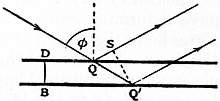
Fig. 5.
A comparison with the method of a material pointer, attached to the parts whose rotation is under observation, and viewed through a microscope, is of interest. The limiting efficiency of the microscope is attained when the angular aperture amounts to 180°; and it is evident that a lateral displacement of the point under observation through ½λ entails (at the old image) a phase-discrepancy of a whole period, one extreme ray being accelerated and the other retarded by half that amount. We may infer that the limits of efficiency in the two methods are the same when the length of the pointer is equal to the width of the mirror.
We have seen that in perpendicular reflection a surface error not exceeding 1⁄8λ may be admissible. In the case of oblique reflection at an angle φ, the error of retardation due to an elevation BD (fig. 5) is
QQ′ − QS = BD sec φ(1 − cos SQQ′) = BD sec φ (1 + cos 2φ) = 2BD cos φ;
from which it follows that an error of given magnitude in the figure of a surface is less important in oblique than in perpendicular reflection. It must, however, be borne in mind that errors can sometimes be compensated by altering adjustments. If a surface intended to be flat is affected with a slight general curvature, a remedy may be found in an alteration of focus, and the remedy is the less complete as the reflection is more oblique.
The formula expressing the optical power of prismatic spectroscopes may readily be investigated upon the principles of the wave theory. Let A0B0 be a plane wave-surface of the light before it falls upon the prisms, AB the corresponding wave-surface for a particular part of the spectrum after the light has passed the prisms, or after it has passed the eye-piece of the observing telescope. The path of a ray from the wave-surface A0B0 to A or B is determined by the condition that the optical distance, ∫ μ ds, is a minimum; and, as AB is by supposition a wave-surface, this optical distance is the same for both points. Thus
∫ μ ds (for A) = ∫ μ ds (for B) (4).
We have now to consider the behaviour of light belonging to a neighbouring part of the spectrum. The path of a ray from the wave-surface A0B0 to the point A is changed; but in virtue of the minimum property the change may be neglected in calculating the optical distance, as it influences the result by quantities of the second order only in the changes of refrangibility. Accordingly, the optical distance from A0B0 to A is represented by ∫(μ + δμ)ds, the integration being along the original path A0 ... A; and similarly the optical distance between A0B0 and B is represented by ∫ (μ + δμ)ds, the integration being along B0 ... B. In virtue of (4) the difference of the optical distances to A and B is
∫ δμ ds (along B0 ... B) − ∫ δμ ds (along A0 ... A) (5).
The new wave-surface is formed in such a position that the optical distance is constant; and therefore the dispersion, or the angle through which the wave-surface is turned by the change of refrangibility, is found simply by dividing (5) by the distance AB. If, as in common flint-glass spectroscopes, there is only one dispersing substance, ∫ δμ ds = δμ·s, where s is simply the thickness traversed by the ray. If t2 and t1 be the thicknesses traversed by the extreme rays, and a denote the width of the emergent beam, the dispersion θ is given by
θ = δμ(t2 − t1)/a,
or, if t1 be negligible,
θ = δμt/a (6).
The condition of resolution of a double line whose components subtend an angle θ is that θ must exceed λ/a. Hence, in order that a double line may be resolved whose components have indices μ and μ + δμ, it is necessary that t should exceed the value given by the following equation:—
t = λ/δμ (7).
8. Diffraction Gratings.—Under the heading “Colours of Striated Surfaces,” Thomas Young (Phil. Trans., 1802) in his usual summary fashion gave a general explanation of these colours, including the law of sines, the striations being supposed to be straight, parallel and equidistant. Later, in his article “Chromatics” in the supplement to the 5th edition of this encyclopaedia, he shows that the colours “lose the mixed character of periodical colours, and resemble much more the ordinary prismatic spectrum, with intervals completely dark interposed,” and explains it by the consideration that any phase-difference which may arise at neighbouring striae is multiplied in proportion to the total number of striae.
The theory was further developed by A. J. Fresnel (1815), who gave a formula equivalent to (5) below. But it is to J. von Fraunhofer that we owe most of our knowledge upon this subject. His recent discovery of the “fixed lines” allowed a precision of observation previously impossible. He constructed gratings up to 340 periods to the inch by straining fine wire over screws. Subsequently he ruled gratings on a layer of gold-leaf attached to glass, or on a layer of grease similarly supported, and again by attacking the glass itself with a diamond point. The best gratings were obtained by the last method, but a suitable diamond point was hard to find, and to preserve. Observing through a telescope with light perpendicularly incident, he showed that the position of any ray was dependent only upon the grating interval, viz. the distance from the centre of one wire or line to the centre of the next, and not otherwise upon the thickness of the wire and the magnitude of the interspace. In different gratings the lengths of the spectra and their distances from the axis were inversely proportional to the grating interval, while with a given grating the distances of the various spectra from the axis were as 1, 2, 3, &c. To Fraunhofer we owe the first accurate measurements of wave-lengths, and the method of separating the overlapping spectra by a prism dispersing in the perpendicular direction. He described also the complicated patterns seen when a point of light is viewed through two superposed gratings, whose lines cross one another perpendicularly or obliquely. The above observations relate to transmitted light, but Fraunhofer extended his inquiry to the light reflected. To eliminate the light returned from the hinder surface of an engraved grating, he covered it with a black varnish. It then appeared that under certain angles of incidence parts of the resulting spectra were completely polarized. These remarkable researches of Fraunhofer, carried out in the years 1817-1823, are republished in his Collected Writings (Munich, 1888).
The principle underlying the action of gratings is identical with that discussed in § 2, and exemplified in J. L. Soret’s “zone plates.” The alternate Fresnel’s zones are blocked out or otherwise modified; in this way the original compensation is upset and a revival of light occurs in unusual directions. If the source be a point or a line, and a collimating lens be used, the incident waves may be regarded as plane. If, further, on leaving the grating the light be received by a focusing lens, e.g. the object-glass of a telescope, the Fresnel’s zones are reduced to parallel and equidistant straight strips, which at certain angles coincide with the ruling. The directions of the lateral spectra are such that the passage from one element of the grating to the corresponding point of the next implies a retardation of an integral number of wave-lengths. If the grating be composed of alternate transparent and opaque parts, the question may be treated by means of the general integrals (§ 3) by merely limiting the integration to the transparent parts of the aperture. For an investigation upon these lines the reader is referred to Airy’s Tracts, to Verdet’s Leçons, or to R. W. Wood’s Physical Optics. If, however, we assume the theory of a simple rectangular aperture (§ 3); the results of the ruling can be inferred by elementary methods, which are perhaps more instructive.
Apart from the ruling, we know that the image of a mathematical line will be a series of narrow bands, of which the central one is by far the brightest. At the middle of this band there is complete agreement of phase among the secondary waves. The dark lines which separate the bands are the places at which the phases of the secondary wave range over an integral number of periods. If now we suppose the aperture AB to be covered by a great number of opaque strips or bars of width d, separated by transparent intervals of width a, the condition of things in the directions just spoken of is not materially changed. At the central point there is still complete agreement of phase; but the amplitude is diminished in the ratio of a : a + d. In another direction, making a small angle with the last, such that the projection of AB upon it amounts to a few wave-lengths, it is easy to see that the mode of interference is the same as if there were no ruling. For example, when the direction is such that the projection of AB upon it amounts to one wave-length, the elementary components neutralize one another, because their phases are distributed symmetrically, though discontinuously, round the entire period. The only effect of the ruling is to diminish the amplitude in the ratio a : a + d; and, except for the difference in illumination, the appearance of a line of light is the same as if the aperture were perfectly free.
The lateral (spectral) images occur in such directions that the projection of the element (a + d) of the grating upon them is an exact multiple of λ. The effect of each of the n elements of the grating is then the same; and, unless this vanishes on account of a particular adjustment of the ratio a : d, the resultant amplitude becomes comparatively very great. These directions, in which the retardation between A and B is exactly mnλ, may be called the principal directions. On either side of any one of them the illumination is distributed according to the same law as for the central image (m = 0), vanishing, for example, when the retardation amounts to (mn ± 1)λ. In considering the relative brightnesses of the different spectra, it is therefore sufficient to attend merely to the principal directions, provided that the whole deviation be not so great that its cosine differs considerably from unity.
We have now to consider the amplitude due to a single element, which we may conveniently regard as composed of a transparent part a bounded by two opaque parts of width ½d. The phase of the resultant effect is by symmetry that of the component which comes from the middle of a. The fact that the other components have phases differing from this by amounts ranging between ± amπ/(a + d) causes the resultant amplitude to be less than for the central image (where there is complete phase agreement). If Bm denote the brightness of the mth lateral image, and B0 that of the central image, we have
Bm : B 0 = [∫ + amπ/(a+d) cosx dx ÷ 2amπ ] ² = ( a + d ) ² sin² amπ (1).
− amπ/(a+d) a + d amπ a + d
If B denotes the brightness of the central image when the whole of the space occupied by the grating is transparent, we have
B0 : B = a² : (a + d)²,
and thus
Bm : B = 1 sin² amπ (2).
m²π² a + d
The sine of an angle can never be greater than unity; and consequently under the most favourable circumstances only 1/m²π² of the original light can be obtained in the mth spectrum. We conclude that, with a grating composed of transparent and opaque parts, the utmost light obtainable in any one spectrum is in the first, and there amounts to 1/π², or about 1⁄10, and that for this purpose a and d must be equal. When d = a the general formula becomes
Bm : B = sin² ½mπ (3),
m²π²
showing that, when m is even, Bm vanishes, and that, when m is odd,
Bm : B = 1/m²π².
The third spectrum has thus only 1⁄9 of the brilliancy of the first.
Another particular case of interest is obtained by supposing a small relatively to (a + d). Unless the spectrum be of very high order, we have simply
Bm : B = {a/(a + d)}² (4);
so that the brightnesses of all the spectra are the same.
The light stopped by the opaque parts of the grating, together with that distributed in the central image and lateral spectra, ought to make up the brightness that would be found in the central image, were all the apertures transparent. Thus, if a = d, we should have
1 = ½ + ¼ + 2/π² (1 + 1⁄9 + 1⁄25 + ...),
which is true by a known theorem. In the general case
a = ( a ) ² + 2 Σ m=∞ 1 sin²( mπa ),
a + d a + d π² m=1 m² a + d
a formula which may be verified by Fourier’s theorem.
According to a general principle formulated by J. Babinet, the brightness of a lateral spectrum is not affected by an interchange of the transparent and opaque parts of the grating. The vibrations corresponding to the two parts are precisely antagonistic, since if both were operative the resultant would be zero. So far as the application to gratings is concerned, the same conclusion may be derived from (2).
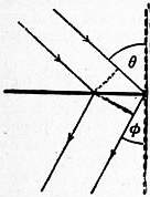
Fig. 6.
From the value of Bm : B0 we see that no lateral spectrum can surpass the central image in brightness; but this result depends upon the hypothesis that the ruling acts by opacity, which is generally very far from being the case in practice. In an engraved glass grating there is no opaque material present by which light could be absorbed, and the effect depends upon a difference of retardation in passing the alternate parts. It is possible to prepare gratings which give a lateral spectrum brighter than the central image, and the explanation is easy. For if the alternate parts were equal and alike transparent, but so constituted as to give a relative retardation of ½λ, it is evident that the central image would be entirely extinguished, while the first spectrum would be four times as bright as if the alternate parts were opaque. If it were possible to introduce at every part of the aperture of the grating an arbitrary retardation, all the light might be concentrated in any desired spectrum. By supposing the retardation to vary uniformly and continuously we fall upon the case of an ordinary prism: but there is then no diffraction spectrum in the usual sense. To obtain such it would be necessary that the retardation should gradually alter by a wave-length in passing over any element of the grating, and then fall back to its previous value, thus springing suddenly over a wave-length (Phil. Mag., 1874, 47, p. 193). It is not likely that such a result will ever be fully attained in practice; but the case is worth stating, in order to show that there is no theoretical limit to the concentration of light of assigned wave-length in one spectrum, and as illustrating the frequently observed unsymmetrical character of the spectra on the two sides of the central image.4
We have hitherto supposed that the light is incident perpendicularly upon the grating; but the theory is easily extended. If the incident rays make an angle θ with the normal (fig. 6), and the diffracted rays make an angle φ (upon the same side), the relative retardation from each element of width (a + d) to the next is (a + d) (sinθ + sinφ); and this is the quantity which is to be equated to mλ. Thus
sinθ + sinφ = 2sin ½(θ + φ) cos ½ (θ − φ) = mλ/(a + d) (5).
The “deviation” is (θ + φ), and is therefore a minimum when θ = φ, i.e. when the grating is so situated that the angles of incidence and diffraction are equal.
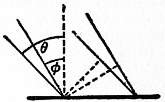
Fig. 7.
In the case of a reflection grating the same method applies. If θ and φ denote the angles with the normal made by the incident and diffracted rays, the formula (5) still holds, and, if the deviation be reckoned from the direction of the regularly reflected rays, it is expressed as before by (θ + φ), and is a minimum when θ = φ, that is, when the diffracted rays return upon the course of the incident rays.
In either case (as also with a prism) the position of minimum deviation leaves the width of the beam unaltered, i.e. neither magnifies nor diminishes the angular width of the object under view.
From (5) we see that, when the light falls perpendicularly upon a grating (θ = 0), there is no spectrum formed (the image corresponding to m = 0 not being counted as a spectrum), if the grating interval σ or (a + d) is less than λ. Under these circumstances, if the material of the grating be completely transparent, the whole of the light must appear in the direct image, and the ruling is not perceptible. From the absence of spectra Fraunhofer argued that there must be a microscopic limit represented by λ; and the inference is plausible, to say the least (Phil. Mag., 1886). Fraunhofer should, however, have fixed the microscopic limit at ½λ, as appears from (5), when we suppose θ = ½π, φ = ½π.
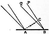
Fig. 8.
We will now consider the important subject of the resolving power of gratings, as dependent upon the number of lines (n) and the order of the spectrum observed (m). Let BP (fig. 8) be the direction of the principal maximum (middle of central band) for the wave-length λ in the mth spectrum. Then the relative retardation of the extreme rays (corresponding to the edges A, B of the grating) is mnλ. If BQ be the direction for the first minimum (the darkness between the central and first lateral band), the relative retardation of the extreme rays is (mn + 1)λ. Suppose now that λ + δλ is the wave-length for which BQ gives the principal maximum, then
(mn + 1)λ = mn(λ + δλ);
whence
δλ/λ = 1/mn (6).
According to our former standard, this gives the smallest difference of wave-lengths in a double line which can be just resolved; and we conclude that the resolving power of a grating depends only upon the total number of lines, and upon the order of the spectrum, without regard to any other considerations. It is here of course assumed that the n lines are really utilized.
In the case of the D lines the value of δλ/λ is about 1/1000; so that to resolve this double line in the first spectrum requires 1000 lines, in the second spectrum 500, and so on.
It is especially to be noticed that the resolving power does not depend directly upon the closeness of the ruling. Let us take the case of a grating 1 in. broad, and containing 1000 lines, and consider the effect of interpolating an additional 1000 lines, so as to bisect the former intervals. There will be destruction by interference of the first, third and odd spectra generally; while the advantage gained in the spectra of even order is not in dispersion, nor in resolving power, but simply in brilliancy, which is increased four times. If we now suppose half the grating cut away, so as to leave 1000 lines in half an inch, the dispersion will not be altered, while the brightness and resolving power are halved.
There is clearly no theoretical limit to the resolving power of gratings, even in spectra of given order. But it is possible that, as suggested by Rowland,5 the structure of natural spectra may be too coarse to give opportunity for resolving powers much higher than those now in use. However this may be, it would always be possible, with the aid of a grating of given resolving power, to construct artificially from white light mixtures of slightly different wave-length whose resolution or otherwise would discriminate between powers inferior and superior to the given one.6
If we define as the “dispersion” in a particular part of the spectrum the ratio of the angular interval dθ to the corresponding increment of wave-length dλ, we may express it by a very simple formula. For the alteration of wave-length entails, at the two limits of a diffracted wave-front, a relative retardation equal to mndλ. Hence, if a be the width of the diffracted beam, and dθ the angle through which the wave-front is turned,
adθ = mn dλ,
or
dispersion = mn/a (7).
The resolving power and the width of the emergent beam fix the optical character of the instrument. The latter element must eventually be decreased until less than the diameter of the pupil of the eye. Hence a wide beam demands treatment with further apparatus (usually a telescope) of high magnifying power.
In the above discussion it has been supposed that the ruling is accurate, and we have seen that by increase of m a high resolving power is attainable with a moderate number of lines. But this procedure (apart from the question of illumination) is open to the objection that it makes excessive demands upon accuracy. According to the principle already laid down it can make but little difference in the principal direction corresponding to the first spectrum, provided each line lie within a quarter of an interval (a + d) from its theoretical position. But, to obtain an equally good result in the mth spectrum, the error must be less than 1/m of the above amount.7
There are certain errors of a systematic character which demand special consideration. The spacing is usually effected by means of a screw, to each revolution of which corresponds a large number (e.g. one hundred) of lines. In this way it may happen that although there is almost perfect periodicity with each revolution of the screw after (say) 100 lines, yet the 100 lines themselves are not equally spaced. The “ghosts” thus arising were first described by G. H. Quincke (Pogg. Ann., 1872, 146, p. 1), and have been elaborately investigated by C. S. Peirce (Ann. Journ. Math., 1879, 2, p. 330), both theoretically and experimentally. The general nature of the effects to be expected in such a case may be made clear by means of an illustration already employed for another purpose. Suppose two similar and accurately ruled transparent gratings to be superposed in such a manner that the lines are parallel. If the one set of lines exactly bisect the intervals between the others, the grating interval is practically halved, and the previously existing spectra of odd order vanish. But a very slight relative displacement will cause the apparition of the odd spectra. In this case there is approximate periodicity in the half interval, but complete periodicity only after the whole interval. The advantage of approximate bisection lies in the superior brilliancy of the surviving spectra; but in any case the compound grating may be considered to be perfect in the longer interval, and the definition is as good as if the bisection were accurate.

Fig. 9.—x². Fig. 10.—y². Fig. 11.—x³. Fig. 12.—xy².
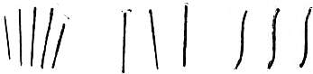
Fig. 13.—xy. Fig. 14.—x²y. Fig. 15.—y³.
The effect of a gradual increase in the interval (fig. 9) as we pass across the grating has been investigated by M. A. Cornu (C.R., 1875, 80, p. 655), who thus explains an anomaly observed by E. E. N. Mascart. The latter found that certain gratings exercised a converging power upon the spectra formed upon one side, and a corresponding diverging power upon the spectra on the other side. Let us suppose that the light is incident perpendicularly, and that the grating interval increases from the centre towards that edge which lies nearest to the spectrum under observation, and decreases towards the hinder edge. It is evident that the waves from both halves of the grating are accelerated in an increasing degree, as we pass from the centre outwards, as compared with the phase they would possess were the central value of the grating interval maintained throughout. The irregularity of spacing has thus the effect of a convex lens, which accelerates the marginal relatively to the central rays. On the other side the effect is reversed. This kind of irregularity may clearly be present in a degree surpassing the usual limits, without loss of definition, when the telescope is focused so as to secure the best effect.
It may be worth while to examine further the other variations from correct ruling which correspond to the various terms expressing the deviation of the wave-surface from a perfect plane. If x and y be co-ordinates in the plane of the wave-surface, the axis of y being parallel to the lines of the grating, and the origin corresponding to the centre of the beam, we may take as an approximate equation to the wave-surface
z = x² + Bxy + y² + αx³ + βx²y + γxy² + δy³ + ... (8);
2ρ 2ρ′
and, as we have just seen, the term in x² corresponds to a linear error in the spacing. In like manner, the term in y² corresponds to a general curvature of the lines (fig. 10), and does not influence the definition at the (primary) focus, although it may introduce astigmatism.8 If we suppose that everything is symmetrical on the two sides of the primary plane y = 0, the coefficients B, β, δ vanish. In spite of any inequality between ρ and ρ’, the definition will be good to this order of approximation, provided α and γ vanish. The former measures the thickness of the primary focal line, and the latter measures its curvature. The error of ruling giving rise to α is one in which the intervals increase or decrease in both directions from the centre outwards (fig. 11), and it may often be compensated by a slight rotation in azimuth of the object-glass of the observing telescope. The term in γ corresponds to a variation of curvature in crossing the grating (fig. 12).
When the plane zx is not a plane of symmetry, we have to consider the terms in xy, x²y, and y³. The first of these corresponds to a deviation from parallelism, causing the interval to alter gradually as we pass along the lines (fig. 13). The error thus arising may be compensated by a rotation of the object-glass about one of the diameters y = ± x. The term in x²y corresponds to a deviation from parallelism in the same direction on both sides of the central line (fig. 14); and that in y³ would be caused by a curvature such that there is a point of inflection at the middle of each line (fig. 15).
All the errors, except that depending on α, and especially those depending on γ and δ, can be diminished, without loss of resolving power, by contracting the vertical aperture. A linear error in the spacing, and a general curvature of the lines, are eliminated in the ordinary use of a grating.
The explanation of the difference of focus upon the two sides as due to unequal spacing was verified by Cornu upon gratings purposely constructed with an increasing interval. He has also shown how to rule a plane surface with lines so disposed that the grating shall of itself give well-focused spectra.
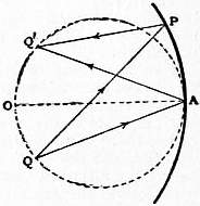
Fig. 16.
A similar idea appears to have guided H. A. Rowland to his brilliant invention of concave gratings, by which spectra can be photographed without any further optical appliance. In these instruments the lines are ruled upon a spherical surface of speculum metal, and mark the intersections of the surface by a system of parallel and equidistant planes, of which the middle member passes through the centre of the sphere. If we consider for the present only the primary plane of symmetry, the figure is reduced to two dimensions. Let AP (fig. 16) represent the surface of the grating, O being the centre of the circle. Then, if Q be any radiant point and Q’ its image (primary focus) in the spherical mirror AP, we have
1 + 1 = 2cosφ ,
v1 u a
where v1 = AQ′, u = AQ, a = OA, φ = angle of incidence QAO, equal to the angle of reflection Q′AO. If Q be on the circle described upon OA as diameter, so that u = a cos φ, then Q′ lies also upon the same circle; and in this case it follows from the symmetry that the unsymmetrical aberration (depending upon a) vanishes.
This disposition is adopted in Rowland′s instrument; only, in addition to the central image formed at the angle φ′ = φ, there are a series of spectra with various values of φ’, but all disposed upon the same circle. Rowland’s investigation is contained in the paper already referred to; but the following account of the theory is in the form adopted by R. T. Glazebrook (Phil. Mag., 1883).
In order to find the difference of optical distances between the courses QAQ′, QPQ′, we have to express QP − QA, PQ′ − AQ′. To find the former, we have, if OAQ = φ, AOP = ω,
QP² = u² + 4a²sin²½ω − 4au sin ½ω sin (½ω − φ) = (u + a sin φ sin ω)² − a² sin²φ sin²ω + 4a sin² ½ω(a − u cosφ).
Now as far as ω4
4 sin² ½ω = sin²ω + ¼sin4ω,
and thus to the same order
QP² = (u + a sin φ sin ω)² − a cos φ(u − a cos φ) sin²ω + ¼ a(a − u cos φ) sin4 ω.
pose that Q lies on the circle u = a cos φ, the middle term vanishes, and we get, correct as far as ω4,
QP = (u + a sin φ sin ω) √ {1 + a² sin² φ sin4ω };
4u
so that
QP − u = a sin φ sin ω + 1⁄8a sin φ tan φ sin4 ω (9),
in which it is to be noticed that the adjustment necessary to secure the disappearance of sin²ω is sufficient also to destroy the term in sin³ω.
A similar expression can be found for Q’P − Q′A; and thus, if Q′A = v, Q′AO = φ′, where v = a cos φ′, we get
QP + PQ′ − QA -AQ′ = a sin ω (sin φ − sin φ′) + 1⁄8a sin4 ω (sin φ tan φ + sin φ′ tan φ′) (10).
If φ′ = φ, the term of the first order vanishes, and the reduction of the difference of path via P and via A to a term of the fourth order proves not only that Q and Q′ are conjugate foci, but also that the foci are exempt from the most important term in the aberration. In the present application φ′ is not necessarily equal to φ; but if P correspond to a line upon the grating, the difference of retardations for consecutive positions of P, so far as expressed by the term of the first order, will be equal to ± mλ (m integral), and therefore without influence, provided
σ (sin φ − sinφ′) = ± mλ (11),
where σ denotes the constant interval between the planes containing the lines. This is the ordinary formula for a reflecting plane grating, and it shows that the spectra are formed in the usual directions. They are here focused (so far as the rays in the primary plane are concerned) upon the circle OQ′A, and the outstanding aberration is of the fourth order.
In order that a large part of the field of view may be in focus at once, it is desirable that the locus of the focused spectrum should be nearly perpendicular to the line of vision. For this purpose Rowland places the eye-piece at O, so that φ = 0, and then by (11) the value of φ′ in the mth spectrum is
σ sin φ’ = ± mλ (12).
If ω now relate to the edge of the grating, on which there are altogether n lines,
nσ = 2a sin ω,
and the value of the last term in (10) becomes
1⁄16 nσsin³ ω sin φ′ tan φ′,
or
1⁄16 mnλ sin³ω tan φ′ (13).
This expresses the retardation of the extreme relatively to the central ray, and is to be reckoned positive, whatever may be the signs of ω, and φ′. If the semi-angular aperture (ω) be 1⁄100, and tan φ′ = 1, mn might be as great as four millions before the error of phase would reach ¼λ. If it were desired to use an angular aperture so large that the aberration according to (13) would be injurious, Rowland points out that on his machine there would be no difficulty in applying a remedy by making σ slightly variable towards the edges. Or, retaining σ constant, we might attain compensation by so polishing the surface as to bring the circumference slightly forward in comparison with the position it would occupy upon a true sphere.
It may be remarked that these calculations apply to the rays in the primary plane only. The image is greatly affected with astigmatism; but this is of little consequence, if γ in (8) be small enough. Curvature of the primary focal line having a very injurious effect upon definition, it may be inferred from the excellent performance of these gratings that γ is in fact small. Its value does not appear to have been calculated. The other coefficients in (8) vanish in virtue of the symmetry.
The mechanical arrangements for maintaining the focus are of great simplicity. The grating at A and the eye-piece at O are rigidly attached to a bar AO, whose ends rest on carriages, moving on rails OQ, AQ at right angles to each other. A tie between the middle point of the rod OA and Q can be used if thought desirable.
The absence of chromatic aberration gives a great advantage in the comparison of overlapping spectra, which Rowland has turned to excellent account in his determinations of the relative wave-lengths of lines in the solar spectrum (Phil. Mag., 1887).
For absolute determinations of wave-lengths plane gratings are used. It is found (Bell, Phil. Mag., 1887) that the angular measurements present less difficulty than the comparison of the grating interval with the standard metre. There is also some uncertainty as to the actual temperature of the grating when in use. In order to minimize the heating action of the light, it might be submitted to a preliminary prismatic analysis before it reaches the slit of the spectrometer, after the manner of Helmholtz.
In spite of the many improvements introduced by Rowland and of the care with which his observations were made, recent workers have come to the conclusion that errors of unexpected amount have crept into his measurements of wave-lengths, and there is even a disposition to discard the grating altogether for fundamental work in favour of the so-called “interference methods,” as developed by A. A. Michelson, and by C. Fabry and J. B. Pérot. The grating would in any case retain its utility for the reference of new lines to standards otherwise fixed. For such standards a relative accuracy of at least one part in a million seems now to be attainable.
Since the time of Fraunhofer many skilled mechanicians have given their attention to the ruling of gratings. Those of Nobert were employed by A. J. Ångström in his celebrated researches upon wave-lengths. L. M. Rutherfurd introduced into common use the reflection grating, finding that speculum metal was less trying than glass to the diamond point, upon the permanence of which so much depends. In Rowland’s dividing engine the screws were prepared by a special process devised by him, and the resulting gratings, plane and concave, have supplied the means for much of the best modern optical work. It would seem, however, that further improvements are not excluded.
There are various copying processes by which it is possible to reproduce an original ruling in more or less perfection. The earliest is that of Quincke, who coated a glass grating with a chemical silver deposit, subsequently thickened with copper in an electrolytic bath. The metallic plate thus produced formed, when stripped from its support, a reflection grating reproducing many of the characteristics of the original. It is best to commence the electrolytic thickening in a silver acetate bath. At the present time excellent reproductions of Rowland’s speculum gratings are on the market (Thorp, Ives, Wallace), prepared, after a suggestion of Sir David Brewster, by coating the original with a varnish, e.g. of celluloid. Much skill is required to secure that the film when stripped shall remain undeformed.
A much easier method, applicable to glass originals, is that of photographic reproduction by contact printing. In several papers dating from 1872, Lord Rayleigh (see Collected Papers, i. 157, 160, 199, 504; iv. 226) has shown that success may be attained by a variety of processes, including bichromated gelatin and the old bitumen process, and has investigated the effect of imperfect approximation during the exposure between the prepared plate and the original. For many purposes the copies, containing lines up to 10,000 to the inch, are not inferior. It is to be desired that transparent gratings should be obtained from first-class ruling machines. To save the diamond point it might be possible to use something softer than ordinary glass as the material of the plate.
9. Talbot’s Bands.—These very remarkable bands are seen under certain conditions when a tolerably pure spectrum is regarded with the naked eye, or with a telescope, half the aperture being covered by a thin plate, e.g. of glass or mica. The view of the matter taken by the discoverer (Phil. Mag., 1837, 10, p. 364) was that any ray which suffered in traversing the plate a retardation of an odd number of half wave-lengths would be extinguished, and that thus the spectrum would be seen interrupted by a number of dark bars. But this explanation cannot be accepted as it stands, being open to the same objection as Arago’s theory of stellar scintillation.9 It is as far as possible from being true that a body emitting homogeneous light would disappear on merely covering half the aperture of vision with a half-wave plate. Such a conclusion would be in the face of the principle of energy, which teaches plainly that the retardation in question leaves the aggregate brightness unaltered. The actual formation of the bands comes about in a very curious way, as is shown by a circumstance first observed by Brewster. When the retarding plate is held on the side towards the red of the spectrum, the bands are not seen. Even in the contrary case, the thickness of the plate must not exceed a certain limit, dependent upon the purity of the spectrum. A satisfactory explanation of these bands was first given by Airy (Phil. Trans., 1840, 225; 1841, 1), but we shall here follow the investigation of Sir G. G. Stokes (Phil. Trans., 1848, 227), limiting ourselves, however, to the case where the retarded and unretarded beams are contiguous and of equal width.
The aperture of the unretarded beam may thus be taken to be limited by x = -h, x = 0, y = -l, y= +l; and that of the beam retarded by R to be given by x = 0, x = h, y= -l, y = +l. For the former (1) § 3 gives
− 1 ∫ 0 ∫ +l sin k{ at − ƒ + xξ + yη }dxdy
λƒ −h −l ƒ
= − 2lh · ƒ sin kηl · 2ƒ sin kξh · sin k{at − ƒ − ξh } (1),
λƒ kηl ƒ kξh 2ƒ 2ƒ
on integration and reduction.
For the retarded stream the only difference is that we must subtract R from at, and that the limits of x are 0 and +h. We thus get for the disturbance at ξ, η, due to this stream
− 2lh · ƒ sin kηl · 2ƒ sin kξh · sin k{at − ƒ − R + ξh } (2)
λƒ kηl ƒ kξh 2ƒ 2ƒ
If we put for shortness π for the quantity under the last circular function in (1), the expressions (1), (2) may be put under the forms u sin τ, v sin (τ − α) respectively; and, if I be the intensity, I will be measured by the sum of the squares of the coefficients of sin τ and cos τ in the expression
u sin τ + v sin (τ − α),
so that
I = u² + v² + 2uv cos α,
which becomes on putting for u, v, and α their values, and putting
{ ƒ sin kηl } ² = Q (3),
kηl ƒ
I = Q · 4l² sin² πξh {2 + 2 cos( 2πR − 2πξh )} (4).
π²ξ² λƒ λ λƒ
If the subject of examination be a luminous line parallel to η, we shall obtain what we require by integrating (4) with respect to η from −∞ to +∞. The constant multiplier is of no especial interest so that we may take as applicable to the image of a line
I = 2 sin² πξh {1 + cos( 2πR − 2πξh )} (5).
ξ² λƒ λ λƒ
If R = ½λ, I vanishes at ξ= 0; but the whole illumination, represented by ∫+∞−∞ I dξ, is independent of the value of R. If R = 0, I = (1/ξ²) sin² (2πξh/λƒ), in agreement with § 3, where a has the meaning here attached to 2h.
The expression (5) gives the illumination at ξ due to that part of the complete image whose geometrical focus is at ξ = 0, the retardation for this component being R. Since we have now to integrate for the whole illumination at a particular point O due to all the components which have their foci in its neighbourhood, we may conveniently regard O as origin. ξ is then the co-ordinate relatively to O of any focal point O′ for which the retardation is R; and the required result is obtained by simply integrating (5) with respect to ξ from −∞ to +∞. To each value of ξ corresponds a different value of λ, and (in consequence of the dispersing power of the plate) of R. The variation of λ may, however, be neglected in the integration, except in 2πR/λ, where a small variation of λ entails a comparatively large alteration of phase. If we write
ρ = 2πR/λ (6),
we must regard ρ as a function of ξ, and we may take with sufficient approximation under any ordinary circumstances
ρ = ρ′ + ωξ (7),
where ρ′ denotes the value of ρ at O, and ω is a constant, which is positive when the retarding plate is held at the side on which the lue of the spectrum is seen. The possibility of dark bands depends upon ω being positive. Only in this case can
cos {ρ′ + (ω − 2πh/λƒ) ξ}
retain the constant value -1 throughout the integration, and then only when
ω = 2πh / λƒ (8)
and
cos ρ′ = −1 (9).
The first of these equations is the condition for the formation of dark bands, and the second marks their situation, which is the same as that determined by the imperfect theory.
The integration can be effected without much difficulty. For the first term in (5) the evaluation is effected at once by a known formula. In the second term if we observe that
cos {ρ′ +(ω − 2πh/λƒ) ξ} = cos {ρ′ − g1ξ} = cos ρ′ cos g1ξ + sin ρ′ sin g1ξ,
we see that the second part vanishes when integrated, and that the remaining integral is of the form
w = ∫ +∞ sin² h1ξ cos g1ξ dξ ,
−∞ ξ²
where
h1 = πh/λƒ, g1 = ω − 2πh/λƒ (10).
By differentiation with respect to g1 it may be proved that
w = 0 from g1 = −∞ to g1 = −2h1,
w = ½π(2h1 + g1) from g1 = −2h1 to g1 = 0,
w = ½π(2h1 − g1) from g1 = 0 to g1 = 2h1,
w = 0 from g1 = 2h1 to g1 = ∞.
The integrated intensity, I′, or
2πh1 + 2 cos ρw,
is thus
I′ = 2πh1 (11),
when g1 numerically exceeds 2h1; and, when g1 lies between ±2h1,
I = π{2h1 + (2h1 − √ g1²) cos ρ′} (12).
It appears therefore that there are no bands at all unless ω lies between 0 and +4h1, and that within these limits the best bands are formed at the middle of the range when ω = 2h1. The formation of bands thus requires that the retarding plate be held upon the side already specified, so that ω be positive; and that the thickness of the plate (to which ω is proportional) do not exceed a certain limit, which we may call 2T0. At the best thickness T0 the bands are black, and not otherwise.
The linear width of the band (e) is the increment of ξ which alters ρ by 2π, so that
e = 2π / ω (13).
With the best thickness
ω = 2πh/λƒ (14),
so that in this case
e = λƒ / h (15).
The bands are thus of the same width as those due to two infinitely narrow apertures coincident with the central lines of the retarded and unretarded streams, the subject of examination being itself a fine luminous line.
If it be desired to see a given number of bands in the whole or in any part of the spectrum, the thickness of the retarding plate is thereby determined, independently of all other considerations. But in order that the bands may be really visible, and still more in order that they may be black, another condition must be satisfied. It is necessary that the aperture of the pupil be accommodated to the angular extent of the spectrum, or reciprocally. Black bands will be too fine to be well seen unless the aperture (2h) of the pupil be somewhat contracted. One-twentieth to one-fiftieth of an inch is suitable. The aperture and the number of bands being both fixed, the condition of blackness determines the angular magnitude of a band and of the spectrum. The use of a grating is very convenient, for not only are there several spectra in view at the same time, but the dispersion can be varied continuously by sloping the grating. The slits may be cut out of tin-plate, and half covered by mica or “microscopic glass,” held in position by a little cement.
If a telescope be employed there is a distinction to be observed, according as the half-covered aperture is between the eye and the ocular, or in front of the object-glass. In the former case the function of the telescope is simply to increase the dispersion, and the formation of the bands is of course independent of the particular manner in which the dispersion arises. If, however, the half-covered aperture be in front of the object-glass, the phenomenon is magnified as a whole, and the desirable relation between the (unmagnified) dispersion and the aperture is the same as without the telescope. There appears to be no further advantage in the use of a telescope than the increased facility of accommodation, and for this of course a very low power suffices.
The original investigation of Stokes, here briefly sketched, extends also to the case where the streams are of unequal width h, k, and are separated by an interval 2g. In the case of unequal width the bands cannot be black; but if h = k, the finiteness of 2g does not preclude the formation of black bands.
The theory of Talbot’s bands with a half-covered circular aperture has been considered by H. Struve (St Peters. Trans., 1883, 31, No. 1).
The subject of “Talbot’s bands” has been treated in a very instructive manner by A. Schuster (Phil. Mag., 1904), whose point of view offers the great advantage of affording an instantaneous explanation of the peculiarity noticed by Brewster. A plane pulse, i.e. a disturbance limited to an infinitely thin slice of the medium, is supposed to fall upon a parallel grating, which again may be regarded as formed of infinitely thin wires, or infinitely narrow lines traced upon glass. The secondary pulses diverted by the ruling fall upon an object-glass as usual, and on arrival at the focus constitute a procession equally spaced in time, the interval between consecutive members depending upon the obliquity. If a retarding plate be now inserted so as to operate upon the pulses which come from one side of the grating, while leaving the remainder unaffected, we have to consider what happens at the focal point chosen. A full discussion would call for the formal application of Fourier’s theorem, but some conclusions of importance are almost obvious.
Previously to the introduction of the plate we have an effect corresponding to wave-lengths closely grouped around the principal wave-length, viz. σ sin φ, where σ is the grating-interval and φ the obliquity, the closeness of the grouping increasing with the number of intervals. In addition to these wave-lengths there are other groups centred round the wave-lengths which are submultiples of the principal one—the overlapping spectra of the second and higher orders. Suppose now that the plate is introduced so as to cover naif the aperture and that it retards those pulses which would otherwise arrive first. The consequences must depend upon the amount of the retardation. As this increases from zero, the two processions which correspond to the two halves of the aperture begin to overlap, and the overlapping gradually increases until there is almost complete superposition. The stage upon which we will fix our attention is that where the one procession bisects the intervals between the other, so that a new simple procession is constituted, containing the same number of members as before the insertion of the plate, but now spaced at intervals only half as great. It is evident that the effect at the focal point is the obliteration of the first and other spectra of odd order, so that as regards the spectrum of the first order we may consider that the two beams interfere. The formation of black bands is thus explained, and it requires that the plate be introduced upon one particular side, and that the amount of the retardation be adjusted to a particular value. If the retardation be too little, the overlapping of the processions is incomplete, so that besides the procession of half period there are residues of the original processions of full period. The same thing occurs if the retardation be too great. If it exceed the double of the value necessary for black bands, there is again no overlapping and consequently no interference. If the plate be introduced upon the other side, so as to retard the procession originally in arrear, there is no overlapping, whatever may be the amount of retardation. In this way the principal features of the phenomenon are accounted for, and Schuster has shown further how to extend the results to spectra having their origin in prisms instead of gratings.
10. Diffraction when the Source of Light is not seen in Focus.—The phenomena to be considered under this head are of less importance than those investigated by Fraunhofer, and will be treated in less detail; but in view of their historical interest and of the ease with which many of the experiments may be tried, some account of their theory cannot be omitted. One or two examples have already attracted our attention when considering Fresnel’s zones, viz. the shadow of a circular disk and of a screen circularly perforated.
Fresnel commenced his researches with an examination of the fringes, external and internal, which accompany the shadow of a narrow opaque strip, such as a wire. As a source of light he used sunshine passing through a very small hole perforated in a metal plate, or condensed by a lens of short focus. In the absence of a heliostat the latter was the more convenient. Following, unknown to himself, in the footsteps of Young, he deduced the principle of interference from the circumstance that the darkness of the interior bands requires the co-operation of light from both sides of the obstacle. At first, too, he followed Young in the view that the exterior bands are the result of interference between the direct light and that reflected from the edge of the obstacle, but he soon discovered that the character of the edge—e.g. whether it was the cutting edge or the back of a razor—made no material difference, and was thus led to the conclusion that the explanation of these phenomena requires nothing more than the application of Huygens’s principle to the unobstructed parts of the wave. In observing the bands he received them at first upon a screen of finely ground glass, upon which a magnifying lens was focused; but it soon appeared that the ground glass could be dispensed with, the diffraction pattern being viewed in the same way as the image formed by the object-glass of a telescope is viewed through the eye-piece. This simplification was attended by a great saving of light, allowing measures to be taken such as would otherwise have presented great difficulties.
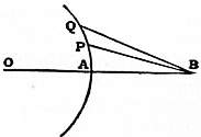
Fig. 17.
In theoretical investigations these problems are usually treated as of two dimensions only, everything being referred to the plane passing through the luminous point and perpendicular to the diffracting edges, supposed to be straight and parallel. In strictness this idea is appropriate only when the source is a luminous line, emitting cylindrical waves, such as might be obtained from a luminous point with the aid of a cylindrical lens. When, in order to apply Huygens’s principle, the wave is supposed to be broken up, the phase is the same at every element of the surface of resolution which lies upon a line perpendicular to the plane of reference, and thus the effect of the whole line, or rather infinitesimal strip, is related in a constant manner to that of the element which lies in the plane of reference, and may be considered to be represented thereby. The same method of representation is applicable to spherical waves, issuing from a point, if the radius of curvature be large; for, although there is variation of phase along the length of the infinitesimal strip, the whole effect depends practically upon that of the central parts where the phase is sensibly constant.10
In fig. 17 APQ is the arc of the circle representative of the wave-front of resolution, the centre being at O, and the radius QA being equal to a. B is the point at which the effect is required, distant a + b from O, so that AB = b, AP = s, PQ = ds.
Taking as the standard phase that of the secondary wave from A, we may represent the effect of PQ by
cos 2π( t − δ )· ds,
r λ
where δ = BP − AP is the retardation at B of the wave from P relatively to that from A.