TRACTION ENGINES.
Reading edition
Traction Farm Engines are becoming more generally used each year, and to supply the increasing demand for traction engines, the manufacturers have spared no expense or mechanical skill to place upon the market the latest improvements in this line, and a great many kinds of this class of engine now made in the United States are simply perfect. They travel over the roughest roads, up and down steep hills with heavy loads, and the engine is at all times entirely under the control of the engineer. In fact, there is no class of engines that has had a more marked advancement toward perfection in the past few years than the farm traction engine.
As this class of engines in the majority of cases goes into the hands of men inexperienced in the handling of machinery, they are subjected to the very hardest usage and neglect, which, of course, hastens their destruction. Every purchaser of an engine should acquire sufficient knowledge of the operating and handling of it so that he will know when it is properly cared for.
No engine has to run at more variable speeds than a traction engine. It is very important for this reason that the steam ports should be of sufficient area to admit of a very high piston speed, and allow the steam to follow the piston at the necessary velocity. Small ports are useless, as when the link is notched up, and the travel of the valve thereby reduced, the openings are too cramped for the steam to pass in and out of the cylinder comfortably. The result is, that the slide valve is forced off its seat and the engine primes as soon as any great speed is attained. It is easy to tell by the sound of the exhaust if the ports are rightly proportioned, and whether running at high or low speed, the engine should give a clear and distinct exhaust at every stroke of the piston.
GEARING.
The power of the traction engine is transmitted to the traction wheels by a series of gearing, all of which should be made from accurately cut patterns to insure the teeth meshing perfectly to prevent them from cutting and grinding out, and of sufficient strength to withstand the very rough usage to which they are subjected. The gearing of an engine should never be run without first greasing them thoroughly with a good quality of solid oil or axle grease, for if once you allow the teeth to cut, it will be impossible to stop them from cutting, the result being they will soon be ruined. The gearing on traction engines are placed in many different positions for transmitting the power to the traction wheels, as will be seen by examining the different illustrations given in this book.
On a side gear engine the power is transmitted from a small pinion on the main shaft to an intermediate gear, from this gear to the differential gear on cross shaft which is placed under the cylindrical part of the boiler against the fire box. To this shaft are keyed two small pinions at each end, which mesh in large spur gears fastened securely to the traction wheels.
On a rear gear engine the power is transmitted from the small pinion on crank shaft to large spur gear attached to one end of cross shaft, which crosses the boiler at the rear end. To the other end of this shaft is attached a small pinion that meshes in the large differential gear which is attached to traction wheel and main axle.
DIFFERENTIAL GEAR.
The gearing on a traction engine must be so designed as to allow one of the ground or traction wheels to run faster than the other, when turning engine either to right or left on the road. To accomplish this, the Differential Gear is made use of, and answers all purposes admirably.
The Differential Gear on many styles of engines is attached to the cross shaft, while on others it is secured to the main axle, and, as generally constructed, consists of one large spur gear, having three or four bevel pinions placed in it at equal distances apart and from the center of main gear. These pinions revolve loosely on pins secured to the gear, and the spur gear runs loosely on the cross shaft or axle. At each side of the spur gear are placed bevel gears, meshing into the bevel pinions, one of which is keyed fast to the shaft or axle, while the other is firmly bolted to small pinion that drives the traction wheel, or to hub of the traction wheel, which also runs loosely on its axle.
This device allows one drive wheel to remain idle while the opposite wheel may revolve as fast as is required to make the turn.
Differential Gears should be kept well greased with solid oil or axle grease to prevent the cogs from being cut and wearing away rapidly.
FRICTION CLUTCH.
This attachment on a traction engine is almost indispensable as it allows the engineer to give the whole power of the engine instantly to the traction gear in getting the engine out of bad places, or to move the engine backward or forward with so little apparent effort as to be almost imperceptible, while the engine may be running at full speed; also for tightening the main drive belt when attached to machinery without stopping the engine.
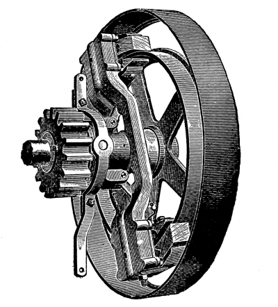
J. I. Case Friction Clutch.
The friction clutch shown in illustration is constructed as follows: The friction pulley is constructed with a friction ring upon its arms, the outer ring acting as a guard or protection, the friction ring being turned accurately to receive the wooden shoes attached to the driving arm; these wooden friction shoes are fitted to the outer surface of the ring as well as the inner, all being connected to one set of levers; so when force is applied to engage the friction to start the engine there is no tendency or danger of bursting the rim, as the pressure is equal on both sides of it. The pulley is keyed to the crank shaft, while the driving arm, with driving pinion secured firmly to it, runs loosely upon the shaft. Upon the hub of driving arm is placed a sliding sleeve with lever attached, which connects with toggle levers beneath the sliding pieces which contain the wooden friction shoes, the whole being operated by the sliding strap from footboard of engine near by the reverse lever. This makes a strong and convenient arrangement for transmitting power.
Many other styles of clutches are made by engine builders, adapted to their particular style of engines, a common way being to have the shoes tighten against the inner rim of the fly-wheel. This is not deemed as good an arrangement, for the reason that the pressure or strain is all outward against the rim, though their being used extensively indicates good results.
When operating a friction clutch, always draw or push the lever over gradually. By doing this the engine will start slowly and easily, while if the lever is jammed over suddenly, the engine will start with a jerk, which is liable to damage the traction gear. The latter should never be done unless absolutely necessary to get the engine out of bad places on the road.