STEAM ENGINES.
Reading edition
All styles of engines both large and small should receive proper attention. All the vibrating and moving parts should be kept well oiled and free from grit and dirt. If this is neglected, the friction of the moving parts will soon wear away the metal and induce pounding and cause what is called “lost motion,” which detracts greatly from the power of the engine, and if allowed to run in this condition will soon necessitate large expense for repairs and shorten the life of the engine.
Tighten all the boxes as they wear, being careful not to get them too tight. Keep the piston rod and valve rod well packed with a good quality of soft packing. Keep the valve or valves set properly to give the required amount of lap and lead and an equal cut-off at the end of each stroke whether working in full gear or notched up.
Keep the cross-head shoes fitted properly in the guides, being careful to keep the piston rod in line. If the above instructions are followed, your engine will run smoothly and do good service.
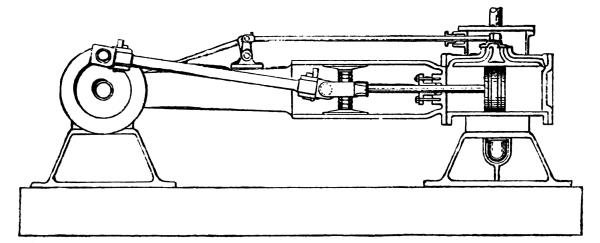
Sectional View of Simple Engine,
Showing Cylinder, Steam Chest, Plain Slide Valve, Steam and Exhaust Ports, Piston and Rod, Engine Frame, Cross-head, Connecting Rod, Crank Disc, and Rocker Arm and Rod for Operating Valve.
STEAM CYLINDER.
The Steam Cylinder is that part of an engine in which the piston travels; it also contains the steam and exhaust ports and is one of the most expensive, as well as essential, parts of an engine. The cylinder should be made of the best quality of cast iron, and the greatest care taken in boring it perfectly true and round. It should be counter-bored at each end to allow the piston in its travel to overlap at the end of each stroke. Without the counter-bore, a shoulder would be formed at both ends of the cylinder as it became worn by the piston rings, which in time would cause a knock or pound at the end of every stroke; the only remedy being to have the cylinder re-bored.
Special attention should be paid to keeping the cylinder well oiled with the best quality of cylinder oil to prevent it from being cut by the piston rings. If allowed to run dry and cut, it will cause no end of trouble.
The size of cylinder is not always the measure of the power of the engine. The power depends upon the heating surface of the boiler and steam pressure; as the piston speed can always be increased, by running the engine faster, until the maximum evaporating capacity of the boiler is reached.
PISTON AND ROD.
The Piston is another very important part in the construction of an engine, and it conveys the power of the steam to the crank. It is composed of a piston head, on which are placed the piston rings held in position by the follower plate, and is securely attached to the piston rod. Great care should be taken in the construction of the piston rings to have them fit the cylinder perfectly tight, at the same time to have the least possible friction. Piston rings should always be made of a softer metal than the cylinder so that the greater part of the wear will be upon the rings instead of the cylinder, as the rings can easily be replaced.
There are a great many kinds of packing for piston rings, but the most commonly used at the present time are the steam packing rings. The character, accuracy in construction and condition of the piston make a great difference in the quantity of fuel consumed and the amount of power developed by the engine.
The Piston Rod connects the piston to the cross-head and is generally made of steel. Where the piston rod enters the cylinder, a steam tight joint is obtained by the use of a soft, pliable packing placed in the stuffing box, and held in position by the stuffing box gland.
This box is kept packed just tight enough to prevent leaking, by drawing up the stuffing box gland when required. This can be repeated until the packing is all used up, when box must be repacked.
STEAM CHEST.
The Steam Chest contains the valve, and can be on either side of cylinder as may best suit the style of engine. Steam is admitted into the steam chest, and passes into the cylinder by the action of the valve.
Many engine builders cast cylinder and steam chest in one piece, while others cast them separately and bolt them together. The only advantage of the former over the latter is the absence of one less joint to keep packed.
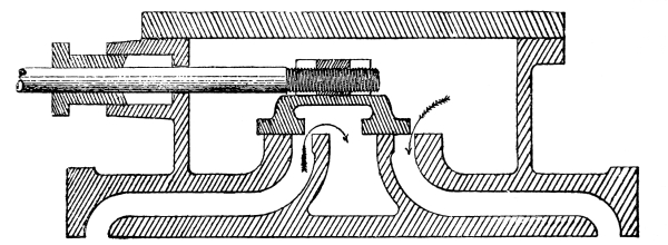
Steam Chest and Plain Slide Valve.
The steam ports are the two openings through which the steam is admitted to the cylinder.
The exhaust port is the opening through which the exhaust or waste steam passes out of the cylinder.
VALVE.
There are a great many kinds of valves used on steam engines, namely, the Corliss, Slide, Rocker, Balance, Rotary, etc., but the one most commonly used on farm engines is the plain slide valve, which has been generally adopted by all the larger engine builders in this country. It is simple in design, and when properly set does its work very efficiently. They are less complicated than others and are easily set; they are made in many different designs, but the principle of each is the same.
The slide valve is constructed to slide upon the smooth surface of the valve seat, in which are contained the two steam ports for the admission of steam to each end of the cylinder, and also the exhaust port through which the exhaust or waste steam passes out of the cylinder.
The slide valve is operated by the eccentrics, which are attached to the main crank shaft of the engine and revolve with it, the object of the eccentrics being to move the slide valve back and forth upon its seat to admit the steam alternately through the steam ports to the cylinder.
The valve gear is a most important detail and one upon which the economy of fuel in a great measure depends, and any derangement in this part of an engine causes an immediate increase in the fuel consumed and decrease in the power of the engine.
In a properly constructed valve the slide upon the seat should be reduced to the smallest possible amount, and should be so designed as to give an equal cut-off and release at both ends of the cylinder, whether working full gear or notched up.
The engine should also have the same power whether working forward or backward, and the cut-off should be as sharp as possible.
The more perfect the valve gear the more the engine can be notched up, and thus allow the steam to expand in the cylinder to its utmost. The engine which can be notched up the most is the most economical in fuel and water.
CROSS-HEAD.
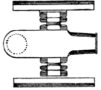
Cross-head.
The Cross-head is of cast iron and connects the piston rod to the connecting rod, and is that part of an engine where the motion is changed from vibrating to rotary. The piston rod is fastened securely to it, while the connecting rod is attached by wrist-pin. On a V guide or bored guide engine frame the cross-head is supplied with adjustable shoe slides that can be adjusted to take up their wear and fit the guides properly, also to keep the piston rod in line. On a bar or locomotive guide engine the cross-head is adjusted by removing the liners from between the bars.
ENGINE FRAME.
The Engine Frame is the large casting which contains the bored, V shaped or locomotive guides for cross-head shoes. It also contains the pillow block for crank shaft at one end and the cylinder is bolted to the other. They are made in many different styles and shapes, but all answer the same purpose.
CONNECTING ROD.
The Connecting Rod on an engine is the connection between the cross-head and crank-pin; it is generally made of wrought iron or steel, with brass boxes at each end held in position by wrought straps. These straps are attached to the connecting rod by gibs and keys. Connecting rods are sometimes made with mortised ends to receive the brass boxes, which are held in place by wedge block and adjusting screw. The latter style is used principally on the larger makes of engines. While the connecting rod with mortised ends are considered a little the safest, the straps on the ends of rods are most commonly used. The brass boxes at ends of connecting rod are adjustable to take up the wear by use of the gibs and keys, and they should be adjusted as frequently as there is any lost motion discovered at the crank-pin or cross-head, which will be indicated by a knocking or pounding as the crank passes over the centers.
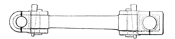
Connecting Rod.
CRANK.
The Crank is that part of an engine by which the effect of the steam acting against the piston is converted into work. There are two kinds, Side and Center crank. The term Side crank refers to a disc plate or a crank attached to one end of a shaft and in which is placed the crank-pin. When the shaft extends to the right the engine is called a right hand engine, and when it extends to the left it is called a left hand engine.
The term Center crank refers to a shaft with the crank in the center, the shaft extending equally both ways and so constructed as to be very well balanced. It is optional as to which gives the best results as both kinds are used upon all sizes of engines.
CRANK-PIN.
The Crank-Pin connects the connecting rod and crank. It is made of steel, and special care should be taken to keep the crank-pin well oiled. If allowed to run dry and cut, it will soon heat and ruin both pin and boxes. If once allowed to become cut, it will be impossible to prevent it from heating.
LINK REVERSE.
The Link Reverse is composed of two eccentrics and rods, link, block and slide, also lever and quadrant for holding link in any position. The duty of the link is to reverse the engine by simply throwing the reverse lever backward and forward. The speed of the engine can also be reduced and increased by the same operation.
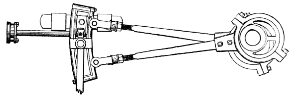
Link Reverse.
RUMELY TRACTION ENGINE.
In the construction of this engine, which is of the side crank, rear gear style, it will be seen that the engine is in a different position upon the boiler from the ordinary side crank, having the cylinder forward, and the crank shaft at the rear end. The frame is of the girder pattern, with overhanging cylinder attached to one end, the pillow block bearing at the other, and is secured to the boiler by two brackets.
The engine is supplied with a Cross-head Pump, Link Reverse Gear, Friction Clutch, Automatic Oiler, Governor, Large Cylindrical Water Tank on the side, and Tool Boxes upon the Platform.
The boiler is of the round bottom fire box or locomotive style, has the dome in front, and the ash pan is in the lower part of the fire box.
It is mounted upon the traction wheels by brackets attached to the rear end of the boiler, which contain the main axle. The front end rests upon a trussed axle.
The traction wheels are high, and are of the wrought iron rim direct spoke type. The loose traction wheel is furnished with a locking device for securing it to the axle.
In the arrangement of the engine and the high traction wheels, the driving or band wheel is placed between one of the traction wheels and the boiler. The necessary fittings are furnished with both boiler and engine to keep them in good running order and perfectly safe if properly handled.
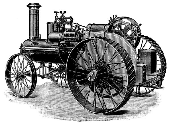
Rumely Traction Engine.
LINK.
The Link is that part which holds the link block and is connected at each end to the eccentric rods; it is used only on reversing engines. The link is made on a curve, so that when the link block is at either extreme end the valve is operated to its full movement. When the block is in the center of link, the valve covers both ports and prevents the ingress of steam to the cylinder.
The Link Block is attached to the slide which connects it to the valve rod. The valve rod connects the slide and valve, and where it enters the steam chest is packed in like manner to the piston rod.
REVERSE LEVER.
The Reverse Lever is that part of the valve gear connected with the link for raising and lowering it, thereby changing the travel of the valve and reversing the motion of the engine. When the reverse lever is placed in the center notch of quadrant, the lap of slide valve should cover both steam ports, preventing any steam from entering the cylinder, thus stopping the engine. In moving this lever from the center notch, it either drops or raises the link as the case may be, increasing the travel of the valve and allowing steam to enter the cylinder. When the reverse lever is thrown into the outside notch of quadrant at either end you get full travel of the valve which gives full power of engine, providing you have sufficient steam pressure.
ECCENTRICS.
The Eccentric on an engine is for the purpose of moving the valve back and forth upon the valve seat and has a throw equal to the travel of the valve. The throw of eccentric is caused by the wheel or plate being bored to one side of its true center, and generally equals one-half the travel of the valve. If more or less, the difference is caused by the use of rocker arm or similar devices for increasing or diminishing the throw of eccentric as the case may be. The eccentric is accurately fitted and fastened to the main shaft of the engine with set screws or key.
ECCENTRIC STRAP.
The Eccentric Strap is that part of the engine in which the eccentric revolves, and is attached to link by the eccentric rod. It should be kept well oiled to secure a free and easy movement to the link.
On reversing engines there are two eccentrics exactly alike, one connecting with upper end of link, the other with lower end by the eccentric straps and rods. In this case the eccentric rod that is moving the valve is the one nearest to the link block. When the lever is in the center notch the link is also in the center of its travel. In this case, both of the eccentric rods move an equal distance and the link vibrates back and forth, but as the block is in the center it gives no motion to the valve, and as the valve, having sufficient lap, covers both ports when the lever is in this position prevents the ingress of steam to the cylinder, consequently no motion.
ECCENTRIC ROD.
The Eccentric Rod connects the eccentric to the link, two being used on a reversing engine. On a simple engine only one eccentric rod is used and is connected to a rocker arm which is attached to the valve rod.
WOOLF VALVE GEAR.
The Woolf Valve Gear is used in connection with an engine to reverse its motion. It is arranged with one eccentric attached to the crank shaft the strap of which has a long arm cast on, to which the eccentric rod that moves the valve is attached. This arm is also supplied with a roller, which runs in a slot on a rocking head. This head is held in position by a box and is connected to the reverse lever by a rod. By throwing the reverse lever to either end of the quadrant, the position of the rocking head is so placed that the roller in the slide operates the eccentric strap, rod and valve, and the engine will run in the direction desired. By throwing the reverse lever to the opposite end of the quadrant, the position of the rocking head is so changed that it will reverse the motion of the valve, and the engine will run in the opposite direction.
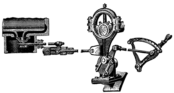
Woolf Valve Gear.
The Quadrant being notched, the point of cut-off can be regulated with the reverse lever, according to the load; by placing it in the last notch in quadrant when full power of engine is required, or notching it up when doing light work, the same as with the link reverse gear.
GOVERNOR.
The Governor contains a valve so constructed and connected with the weighted balls that an increase of speed of the engine throws out the balls, which raises the arms attached to valve rod, thereby closing the valve and thus decreases the flow of steam through the governor valve and reduces the speed of engine until the governor balls are again in their true position. Now, when the speed decreases and the weighted balls rise above their true position, the valve opens, allows more steam to enter the cylinder and the speed of the engine increases until the engine is again running at its proper speed.
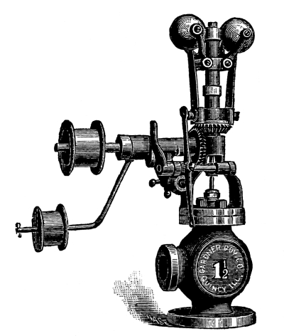
Gardner Governor.
Governors are used to regulate the quantity of steam required to run an engine at a uniform speed under variation of load, and to run properly they should be kept perfectly clean and free from the accumulation of gummy substances caused by using inferior oil, which has a tendency to interfere with the free and easy movement of the different parts.
Q. If you desire to run your engine faster or slower with the throttle valve wide open, how can it be done?
A. Some makes of governors are provided with regulating screws at the top; by turning the hand nut in one direction you lengthen the valve stem and reduce the steam opening in the governor valve, which reduces the speed.
To increase the speed of the engine the handle nut is turned the opposite direction, which shortens the stem and increases the opening in governor valve, allowing more steam to enter the cylinder and the speed is proportionately increased.
The Gardner Governors are provided with a hand screw at the side for regulating the speed, as will be seen by examining the accompanying cut. It also has a Sawyer’s Lever for opening the valve to its full extent, and a belt tightener.
Q. Will the handle nut stay in position after once being set to a certain speed?
A. Not unless the check nut directly over the handle nut is screwed down tight to prevent the stem from changing its position.
Q. Is a governor liable to cause trouble and fail to govern the engine properly?
A. All governors are more or less delicate in construction and must be kept clean and well oiled, the belt must not be allowed to slip, nor must it be so tight as to cause the governor to work hard. The small stuffing box that packs the valve stem should never be screwed down steam tight, as it causes too much friction on the stem and prevents the balls from operating it, and the engine will run unsteadily and spasmodically. Always allow the stuffing box to leak a little, then you know it is not too tight.
First class governors may sometimes be condemned for not regulating the engine to a uniform speed, when a good cleaning, oiling or loosening of the valve stem stuffing box nut would allow them to work perfectly.
AUTOMATIC OILER.
An Automatic Oiler is used on an engine to keep the cylinder, piston and valve lubricated, and is most essential for the safety and easy operation of these parts. It works automatically and is supplied with a glass tube through which the oil can be seen passing into the cylinder. The feed can be regulated to allow just the required amount of oil to pass into the cylinder.
Where a sight-feed automatic oiler is used on an engine there can be no excuse whatever for the engineer to allow the cylinder to run dry and cut, as he at all times can see whether oil is passing into it or not.
Q. How do you fill an automatic oiler?
A. Close valves D and E, open valve G to draw off the water. Close valve G and take out filling plug C, fill A with oil and replace plug C, then open valve D, and the flow of oil to the cylinder can be regulated with valve E.
Q. Will the oil feed as soon as the oiler is filled?
A. No; time must be given for sight-feed glass and condensing chamber to fill with water of condensation.
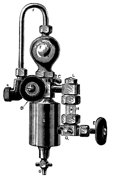
DESCRIPTION.
A. Oil Reservoir.
C. Filler Plug.
D. Water Feed Valve.
E. Regulating Valve.
F. Condensing Chamber.
G. Drain Valve.
H. Sight-Feed Glass.
L. Plug to Insert Glass.
K. Connection to Steam Pipe or Steam Chest.
Q. Drain Valve for Sight-Feed Glass.
Single Connection Detroit Oiler.
Q. How is a double connection automatic oiler attached?
A. First, the steam pipe must be drilled and tapped above the throttle with ½ or ¾ inch gas tap, as may be necessary to receive the oil discharge pipe of oiler and put oiler in place. Then tap the steam pipe about 18 inches if possible above the top of the condensing chamber and fit in a ¼ inch gas pipe for steam connecting tube, which attaches to the top of condensing chamber. (See illustration.)
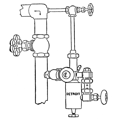
Double Connection Detroit Oiler.
Where the steam pipe cannot be tapped 18 inches above the condensing chamber, it may be tapped lower down and the steam connecting tube of required length be bent in a horizontal coil. With the single connection oiler it is only necessary to drill and tap one hole in the steam pipe.
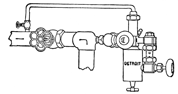
Double Connection Detroit Oiler.
Q. Should oiler become clogged, how can it be cleaned?
A. Open the valves, by which steam can be forced through it, and all the passages will be cleaned. This can be done without stopping the engine.
Q. If oiler is not in use and in danger of freezing, what should be done?
A. Leave valves D, G and E open, and all water will be drained off.
Q. If the glass tube in oiler should get broken, what should be done?
A. Shut valves D and E, remove broken glass and replace with new.
Q. How can oil be prevented from sticking to lubricator glasses?
A. A very simple remedy is to fill the glass with glycerine and let the oil feed through it.
INJECTOR.
An Injector is an automatic machine attached to a boiler, for injecting or forcing water into it and at the same time heating the water to a very high temperature, which saves fuel and prevents the danger of sudden contraction of the plates and flues. It can be used independently and is indispensable on a farm engine.
In piping an injector to boiler, use as short and as straight pipes as possible and especially avoid short turns. Take steam directly from boiler, and have a globe valve in steam pipe close to injector; have the water suction or supply pipe independent of any other connection, and it must be supplied with a globe valve close to injector. This pipe and connections must be absolutely air tight; the slightest leak will cause trouble. The discharge pipe to boiler must be supplied with a tight and reliable check valve. If valve leaks, the injector will become hot and cause no end of annoyance. It is a good plan to put a stop valve between check and boiler in discharge pipe, so that check valve maybe taken off and repaired, or a new one put on without loss of time. A foot of straight pipe screwed into the overflow assists in starting an injector, especially at low pressure.
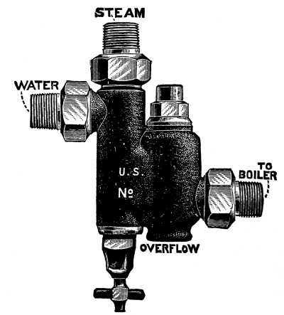
American U. S. Injector.
Q. How do you start an injector to work?
A. To start an injector, open the suction valve wide, then open steam valve. If water appears at the overflow, close and open quickly the suction valve, opening only about ¼ of a turn if at low steam pressure, and one turn or more if at high steam pressure, regulating the water supply according to steam pressure. The injector is controlled entirely by the valve in suction pipe, or by the suction lever after the steam is turned on.
Q. Will an injector work with hot supply water?
A. An injector will not work if the water that is delivered from the tank is too hot to condense the steam.
Q. What are the principal causes of an injector not working accurately?
A. Leak in suction pipe, supply cut off by strainer being clogged, loose lining inside the hose, leak in the stem of valve, too little steam pressure to lift, dirt in the tubes, red lead blown or drawn in through steam or supply pipe, bad check valve, not lift enough or none at all, new boiler full of grease, wet steam, obstruction in the connection to the boiler.
If injector fails, examine at all of these points before condemning. The most common trouble is a leaky suction.
In describing the method of connection and operating an injector the foregoing may have to be modified in some instances, as there are a great many different kinds and styles of injectors which operate and connect differently, but the above if followed carefully and with a little discretion will be found useful.
Bear in mind, however, that the injector does not start to work to boiler as soon as it gets the water. At first the water will run out of the overflow. At this point you start the injector working to the boiler by closing and opening the water valve as quickly as possible with a jerk, or as nearly with one motion as you can.
Q. How do you find the maximum and minimum capacity of injectors?
A. Injectors are controlled entirely by the suction valve after steam is turned on. To find the maximum capacity of an injector after starting, gradually open the suction valve in supply pipe until steam “breaks” and water comes out of the overflow, then start the injector again and you will know about how far the suction valve can be opened without causing the “break.”
To find the minimum capacity of the injector, manipulate the suction valve in the same manner in exactly the opposite direction.
DIRECTIONS FOR OPERATING WORLD INJECTOR.
See that the injector is shut off when put on, by turning the handle as far to the right as it will go. To start, turn handle to the left one-quarter turn; when the water appears at the overflow, turn the handle slowly to the left as far as it will go, and the injector will be working to the boiler.
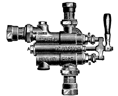
American World Injector.
If steam is high and lift long, the injector will lift the water better if the handle is turned a little less than a quarter of a turn, until the water appears at overflow—then start to boiler as before.
If you have valves in steam and suction pipes, be sure and open them before starting.
Q. How high will an injector draw its supply?
A. About twenty feet is the limit.
Q. How hot does an injector deliver water?
A. From 150 degrees to 200 degrees, according to the steam pressure and the proportions of its capacity at which injector is working.
Q. How should the jets be cleaned when they become scaled?
A. By soaking in diluted muriated acid, about one part acid to ten parts water.
THROTTLE.
The Throttle on an engine is the valve which allows the steam to enter or be shut off from the cylinder and should always be left wide open on a governor engine when running, as the governor regulates the quantity of steam required to run it at its proper speed and is much more economical.
There are different styles of valves used for throttles, such as Globe Valves, Butterfly Valves, Disc Valves, etc.
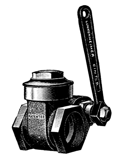
Lunkenheimer Throttle Valve.
The Lunkenheimer is a double disc valve, and is operated by the handle or rod attachment, and requires no lock or ratchet.